1
PARTNER
Advanced Communications System
1600 DSL Module User Guide
Issue 1
May 2001
Table of contents
1. Introduction ...................................................................11
Organization of this guide ..................................................... 11
2. PARTNER ACS 1600 DSL module basics....................13
Hardware and software requirements ................................... 13
Connectors............................................................................ 13
Console cable .................................................................. 13
Interfaces......................................................................... 13
Front View............................................................................. 14
Connecting............................................................................ 15
Logging on ............................................................................ 15
Using a terminal emulation program ................................ 16
Using a Telnet program ................................................... 17
Menu interface ...................................................................... 20
Default values .................................................................. 20
Restarting.............................................................................. 20
Auto Log off........................................................................... 21
Exiting ................................................................................... 21
Verifying an IP address ......................................................... 21
A computer running Windows 95/98/Me/2000 ................. 21
The PARTNER ACS 1600 DSL module .......................... 22
Avaya, Inc.
-i-
PARTNER ACS 1600 DSL module User Guide
4. Menu interface...............................................................23
Main Menu ............................................................................ 23
1. Reports Menu.................................................................... 24
C. Display Current Configuration ..................................... 24
N. Display Network Statistics ........................................... 26
I. Display Interface Statistics............................................ 26
M. Display Media Statistics .............................................. 27
R. Display Route Table.................................................... 28
A. Display ARP Table ...................................................... 28
B. Display Bridge forwarding database............................ 28
S. Display Bridge status................................................... 29
P. Display PPP Authorization Entries .............................. 29
U. Display System Uptime ............................................... 29
2. Configure IP Router .......................................................... 30
C. Configure Port IP Address .......................................... 31
U. Unconfigure Port IP Address....................................... 31
S. Add/Remove a Static Route ........................................ 31
R. Enable/Disable RIP ..................................................... 32
V. Configure RIP Version by Port .................................... 32
P. Configure RIP Poisoned Reverse by Port ................... 32
N. Configure DNS Client.................................................. 33
H. Configure DHCP Client ............................................... 33
L. Configure DHCP Relay................................................ 33
T. Configure Telnet Server Port ....................................... 34
F. Configure IP Filtering................................................... 34
D. Display Route Table.................................................... 39
3. Configure Bridge ............................................................... 40
G. Enable/Disable Bridging Globally................................ 41
P. Enable/Disable Bridging by Port.................................. 41
A. Configure Bridge Aging Timer ..................................... 41
T. Enable/Disable Spanning Tree Globally ...................... 41
Avaya, Inc.
- ii - PARTNER ACS 1600 DSL module User Guide
O. Enable/Disable Spanning Tree by Port ....................... 41
R. Configure Spanning Tree Bridge Priority..................... 41
Q. Configure Spanning Tree Port Priority ........................ 42
H. Configure Spanning Tree Hello Time .......................... 42
S. Configure Spanning Tree Max Age ............................. 42
F. Configure Spanning Tree Forward Delay .................... 42
C. Configure Spanning Tree Path Cost ........................... 42
D. Delete Bridge Forwarding Database Entry.................. 43
5. Configure WAN ................................................................. 44
0. Quick Configuration ..................................................... 45
1. Configure Datalink Protocol ......................................... 45
2. Configure Physical Interface ........................................ 46
3. Configure DLCIS (Frame Relay).................................. 48
3. Configure PVCS (ATM) ............................................... 51
4. Configure FR Options (Frame Relay) .......................... 55
4. Configure ATM Options (ATM) .................................... 57
6. Configure LAN................................................................... 58
F. Set/Clear Full Duplex................................................... 58
7. Configure SNMP ............................................................... 58
E. Enable/Disable SNMP ................................................. 58
P. Configure System Contact .......................................... 58
N. Configure System Name ............................................. 58
L. Configure System Location.......................................... 58
C. Configure SNMP Community ...................................... 59
T. Configure SNMP Trap Host IP Address ...................... 59
8. Configure Login................................................................. 59
1. Change User ID ........................................................... 59
2. Change User Password ............................................... 59
3. Change NetMan Password .......................................... 59
9. System Utilities.................................................................. 60
P. Ping Utility ................................................................... 60
T. Trace Route................................................................. 60
Avaya, Inc.
- iii - PARTNER ACS 1600 DSL module User Guide
Z. Configure Console Baud Rate ..................................... 61
V. Configure Console Timeout......................................... 61
R. Hard Reset or Reload ACOS from FLASH.................. 61
D. Set System Defaults.................................................... 61
W. Save System Settings as Defaults ............................. 61
F. File System Menu........................................................ 61
X. File Transfer Menu ...................................................... 62
I. Interworking Connections................................................... 63
1. Add Interworking Connection....................................... 63
2. Delete Interworking Connection................................... 65
3. Print Interworking Connections .................................... 65
4. Default Interworking Connections ................................ 66
D. Configure DHCP Server ................................................... 66
E. Enable/Disable DHCP ................................................. 66
B. Enable/Disable DHCP Debug Messages .................... 66
I. Configure DHCP Server Parameters ............................ 66
P. Configure DHCP Address Range Pool........................ 67
C. Configure DHCP Client Entry ...................................... 67
F. Display DHCP Configuration ....................................... 68
S. Display DHCP Server Statistics................................... 68
A. Display DHCP Server Assigned Addresses ................ 69
D. Display DHCP Entry Details ........................................ 69
X. Delete a DHCP Client Entry ........................................ 69
Y. Delete a DHCP Assignment Entry............................... 70
N. Configure NAT.................................................................. 70
B. Enable/Disable NAT Debug Messages ....................... 70
P. Enable/Disable NAT Translation by Port ..................... 70
T. Configure NAT TCP Timeout....................................... 70
U. Configure NAT UDP Timeout ...................................... 70
R. Configure NAT Port Range ......................................... 70
N. Configure NAT Local Server Entry .............................. 71
S. Display NAT Statistics ................................................. 71
Avaya, Inc.
- iv - PARTNER ACS 1600 DSL module User Guide
C. Display NAT Connection Table ................................... 72
D. Display NAT Connection Details ................................. 72
O. Display NAT Local Server Table ................................. 72
X. Delete IP Address from NAT Tables ........................... 72
Y. Delete NAT Local Server Entry ................................... 73
T. Derived Timing.................................................................. 73
1. Enable/Disable Derived Timing.................................... 73
2. Enable/Disable Derived Timing Debug Messages....... 73
Z. Diagnostics Menu ............................................................. 74
P. POTS Diagnostics ....................................................... 74
S. SDSL Diagnostics ....................................................... 74
C. Command Line Interface .................................................. 75
Command line syntax ...................................................... 75
Commands ...................................................................... 75
P. VoicePath Configure......................................................... 76
V. Set Voice Gateway...................................................... 76
J. Set Jitter Delay............................................................. 76
D. Display Jitter Delay ..................................................... 77
T. Set SLIC Control Mode................................................ 77
U. Set Compander Mode (u-Law, a-Law) ........................ 77
M. Set Debug Mode......................................................... 78
E. Configure Echo Cancellation Default Settings............. 78
M. Manage MGCP/NCS Embedded Client ........................... 79
C. Configure MGCP/NCS parameters ............................. 79
S. Display MGCP/NCS statistics...................................... 79
D. Debug MGCP/NCS ..................................................... 79
R. Remove a connection ................................................. 79
E. CopperCom Call Control................................................... 80
S. Statistics ...................................................................... 80
C. Configure..................................................................... 80
D. Debug Control ............................................................. 80
Avaya, Inc.
- v - PARTNER ACS 1600 DSL module User Guide
E. Call Control Settings ......................................................... 82
A. Stats Display ............................................................... 82
R. Ring Test..................................................................... 82
S. Display IAD State ........................................................ 83
T. Trace ........................................................................... 83
V. Pick sound heard if insufficient WAN B/W to complete
call ................................................................................... 84
U. Configure Tollbridge Voice Client ..................................... 84
0. Set Client IP address ................................................... 84
1. Set Voice Gateway IP Address.................................... 84
2. Print Current Configuration .......................................... 84
3. Debugging options....................................................... 85
5. Administration...............................................................86
Security ................................................................................. 86
Changing the User ID ...................................................... 87
Changing the Password................................................... 87
Configuring SNMP ................................................................ 88
Enabling/disabling SNMP ................................................ 89
Configuring the System Contact ...................................... 89
Configuring the System Name ......................................... 90
Configuring the System Location ..................................... 91
Configuring the System Community ................................ 92
Configuring the SNMP Trap Host IP Address .................. 93
Upgrading the system ........................................................... 93
Configuring the TFTP Server ........................................... 94
Using TFTP...................................................................... 94
Using Telnet..................................................................... 96
Verifying the download .................................................... 96
Avaya, Inc.
- vi - PARTNER ACS 1600 DSL module User Guide
Upgrading ACOS .................................................................. 97
Configuring the TFTP Server ........................................... 97
Using TFTP...................................................................... 97
Using Telnet..................................................................... 99
Verifying the download .................................................... 99
Support ............................................................................... 100
6. WAN configuration......................................................101
Changing the Datalink Protocol........................................... 101
Configuring the Physical Interface....................................... 102
Configuring the SDSL Interface ..................................... 103
Configuring the USI interface......................................... 104
Quick Configuration............................................................. 107
Configuring ATM PVCs ....................................................... 108
Adding a PVC ................................................................ 109
Modifying a PVC ............................................................ 110
Deleting a PVC .............................................................. 112
Configuring ATM options..................................................... 112
Configuring Payload Scrambling.................................... 113
Configuring the F4 OAM Cell ......................................... 113
Sending OAM Loopback................................................ 114
Configuring Empty Cells ................................................ 115
Configuring Frame Relay DLCIs ......................................... 116
Adding a DLCI ............................................................... 116
Modifying a DLCI ........................................................... 118
Deleting a DLCI ............................................................. 119
Configuring Frame Relay options........................................ 120
Configuring fragmentation ............................................. 120
Configuring the maintenance protocol ........................... 122
Avaya, Inc.
- vii - PARTNER ACS 1600 DSL module User Guide
Configuring the congestion parameters ......................... 123
Configuring the voice path .................................................. 124
Setting the jitter delay .................................................... 124
Setting the SLIC Control Mode ...................................... 125
Configuring Echo Cancellation....................................... 125
7. Router configuration...................................................128
Configuring an IP address................................................... 128
Enabling RIP poisoned reverse........................................... 130
Enabling RIP poisoned reverse globally ........................ 131
Enabling RIP poisoned reverse by port ......................... 132
Setting the RIP version .................................................. 133
Adding a static route ........................................................... 135
Adding a default route ......................................................... 136
Disabling bridging................................................................ 137
Disabling bridging globally ............................................. 137
Disabling bridging by port .............................................. 138
Disabling STP ..................................................................... 139
Disabling STP globally................................................... 139
Disabling STP by port .................................................... 140
8. Bridge configuration...................................................142
Enabling Bridging ................................................................ 143
Enabling bridging globally .............................................. 143
Enabling bridging by port ............................................... 144
Setting the bridge aging timer ........................................ 145
Disabling RIP poisoned reverse .......................................... 146
Disabling RIP poisoned reverse globally ....................... 146
Disabling RIP poisoned reverse by port......................... 147
Avaya, Inc.
- viii - PARTNER ACS 1600 DSL module User Guide
Enabling STP ...................................................................... 148
Enabling STP globally.................................................... 148
Enabling STP by port..................................................... 149
9. NAT configuration.......................................................151
Enabling NAT translation .................................................... 152
Configuring the NAT local server entry ............................... 153
Configuring the NAT timeouts ............................................. 154
Configuring a NAT TCP timeout .................................... 155
Configuring a NAT UDP timeout .................................... 156
Configuring the NAT port range .......................................... 157
10. DHCP server configuration ........................................159
Enabling DHCP ................................................................... 159
Configuring the DHCP server parameters........................... 160
Configuring the DHCP address range pool ......................... 163
11. Verification ..................................................................165
Power-up test ...................................................................... 165
Operational test................................................................... 165
Maintenance ....................................................................... 166
Displaying the current configuration .................................... 167
A. Menu hierarchy............................................................168
Avaya, Inc.
- ix - PARTNER ACS 1600 DSL module User Guide
B. PARTNER ACS 1600 DSL module specifications .....186
C. Connector pinouts ......................................................188
D. USI Cables ...................................................................190
DTE or DCE? ...................................................................... 190
Which Hardware Protocol? ................................................. 190
E. IP Filtering ...................................................................193
Glossary ............................................................................194
Index ..................................................................................199
Avaya, Inc.
- x - PARTNER ACS 1600 DSL module User Guide
1. Introduction
The Avaya PARTNERä Advanced Communications
System(ACS) 1600 DSL module allows you to simultaneously
transport both voice and data services over a DSL, without the
cost of additional lines.
The PARTNER ACS 1600 DSL module supports a variety of
network transports, including ATM and Frame Relay, as well
as SDSL and phone connections.
Supported Interface standards include:
DSL-SDSL (Symmetrical Digital Subscriber Line) that
supplies voice lines and data connection for the
PARTNER ACS System
LAN - 10/100BaseT Ethernet
Console Port (DB9 Connector [RS232 Serial Interface])
USI - V.35 Interface
Organization
of this guide
This user guide contains the following chapters:
Chapter 1, “Introduction”, introduces the PARTNER ACS 1600
DSL module, describes customer support and hardware and
software requirements, as well as the organization of this user
guide.
Chapter 2, “PARTNER ACS 1600 DSL module basics”,
describes the PARTNER ACS 1600 DSL module hardware
and software requirements, as well as the physical IAD.
Chapter 3, “Getting started”, walks you through the
procedures to connect and log on to the PARTNER ACS 1600
DSL module. It also provides information about the Menu
interface, restarting the PARTNER ACS 1600 DSL module,
auto log off, exiting the menu interface and verifying an IP
address.
Chapter 4, “Administration”, provides information about the
PARTNER ACS 1600 DSL module security, as well as how to
configure the Simple Network Management Protocol (SNMP)
and upgrade ACOS.
Chapter 5, “WAN configuration”, details how to configure the
PARTNER ACS 1600 DSL module for voice and data
operation.
Avaya, Inc.
- 11 - PARTNER ACS 1600 DSL module User Guide
Chapter 6, “Router configuration”, describes how to configure
the PARTNER ACS 1600 DSL module as a router.
Chapter 7, “Bridge configuration”, describes how to configure
the PARTNER ACS 1600 DSL module as a bridge.
Chapter 8, “NAT configuration”, walks you through the steps
required to configure the Network Address Translation (NAT).
Chapter 9, “DHCP server configuration”, walks you through
the steps required to configure the Dynamic Host
Configuration Protocol (DHCP) server.
Chapter 10, “Menu interface”, provides information on the
PARTNER ACS 1600 DSL module menus, submenus and
commands.
Chapter 11, “Verification”, describes how to verify that the
PARTNER ACS 1600 DSL module operates properly after
installation. It also covers maintenance, and how to display
the current configuration.
Appendix A, “PARTNER ACS 1600 DSL module menu
hierarchy”, outlines the PARTNER ACS 1600 DSL module
menu interface.
Appendix B, “PARTNER ACS 1600 DSL module
specifications”, lists all specifications for the PARTNER ACS
1600 DSL module.
Appendix C, “Connector pinouts”, provides interface pinout
information.
Appendix D, “USI cables”, provides information about the
various USI cables.
Appendix E, "IP Filtering", provides information about the IP
filtering process.
Avaya, Inc.
- 12 - PARTNER ACS 1600 DSL module User Guide
2. PARTNER ACS 1600 DSL module
basics
This chapter describes the PARTNER ACS 1600 DSL module
hardware and software requirements, as well as the physical
IAD.
Hardware and
software
requirements
You must use a terminal emulation program, such as
HyperTerminal or ProCommPlus, to configure the PARTNER
ACS 1600 DSL module. Once you configure an IP address,
you can also use Telnet to remotely administer the PARTNER
ACS 1600 DSL module. For more information, see the
“Getting started” chapter.
Connectors
The PARTNER ACS 1600 DSL module contains the following
connectors:
Console cable
Connects the PARTNER ACS 1600 DSL module to a local
PC, using a straight through 9 pin serial (DB9 RS 232) cable.
You can then configure the PARTNER ACS 1600 DSL
module using terminal emulation software.
For more
information on configuring the PARTNER ACS 1600 DSL
module, see “PARTNER ACS 1600 DSL module
configuration” later in this chapter.
Interfaces
Available interfaces include the following:
DSL-SDSL (Symmetrical Digital Subscriber Line) that
supplies voice lines and data connection for the
PARTNER ACS System
LAN - 10/100BaseT Ethernet
Console Port (DB9 Connector [RS232 Serial Interface])
USI - V.35 Interface
Avaya, Inc.
- 13 - PARTNER ACS 1600 DSL module User Guide
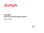
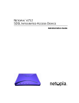
Front View
V.35
Console
DSL Line
PARTNER Power LED
Avaya, Inc.
Ethernet
LAN
- 14 - PARTNER ACS 1600 DSL module User Guide
3.
Getting started
This chapter walks you through the procedures to connect
and log on to the PARTNER ACS 1600 DSL module. It also
provides information about the Menu interface, restarting the
PARTNER ACS 1600 DSL module, auto log off, exiting the
menu interface and verifying an IP address.
For more information on the menus, submenus and
commands in this chapter, see the “Menu interface” chapter.
Connecting
You can configure the PARTNER ACS 1600 DSL module
while connected to a PARTNER system or as a stand-alone
unit.
To configure within the confines of a PARTNER system, you
must place it in the first slot of a 5-slot carrier.
To configure it as a stand-alone unit, you must connect a
power cord to the rear of the PARTNER ACS 1600 DSL
module. For more information on how to connect power to the
unit, see the PARTNER User Guide.
To connect the PARTNER ACS 1600 DSL module to a PC
using a DB9 connector
1. Insert the provided DB9 connector into the serial port
(DB9) connector on the PARTNER ACS 1600 DSL
module.
2. Attach an RS-232 connector to the appropriate COM port
on the PC.
3. Plug the power cable into PARTNER ACS 2 or 5-slot
carrier, and then into a wall outlet.
Once connected, you need to log on to the PARTNER ACS
1600 DSL module.
Logging on
There are two ways that you can log on to the PARTNER
ACS 1600 DSL module:
A terminal emulation program through the console port.
A Telnet program through the Ethernet port.
Avaya, Inc.
- 15 - PARTNER ACS 1600 DSL module User Guide
Using a terminal emulation program
To use a terminal emulation program to log on to a PARTNER
ACS 1600 DSL module
1. Open the terminal emulation program.
2. Select the name, icon and COM port for the PARTNER
ACS 1600 DSL module connection.
3. Type or select the following settings, and then save your
changes.
Bits per second:
19200
Data bits:
8
Parity:
None
Stop bits:
1
Flow control:
None
Emulation:
ANSI
Font:
Terminal
For more information, see your terminal emulation
program documentation.
4. Press ENTER.
The log on message displays.
Enter Login ID >
5. Type your User ID, and press ENTER.
The following are the default User IDs and passwords:
Access Level
User
Network Administrator
User ID
<Enter>
NetMan
Password
<Enter>
<Enter>
For more information, see the "Administration" chapter.
The password message displays.
Enter Password >
6. Type your password, and the press ENTER.
The Main Menu displays.
*****************************************
*
Main Menu
*
*****************************************
1. Reports Menu
2. Configure IP Router
3. Configure Bridge
5. Configure WAN
6. Configure LAN
7. Configure SNMP
Avaya, Inc.
- 16 - PARTNER ACS 1600 DSL module User Guide
8. Configure Login
9. System Utilities
D. Configure DHCP Server
N. Configure NAT
T. Derived Timing
Z. Diagnostics Menu
C. Command Line Interface
P. VoicePath Configure
For more information on the menus, submenus and
commands on the Main Menu, see the “Menu interface”
chapter.
Using a Telnet program
You must set an IP address for the Ethernet port before you
can use a Telnet program to access the PARTNER ACS 1600
DSL module.
Configuring a port IP address
To configure a port IP address:
1. On the Main Menu, select Configure IP Router.
The Router Configuration Menu displays.
*****************************************
*
Router Configuration Menu
*
*****************************************
C. Configure Port IP Address
U. Unconfigure Port IP Address
S. Add/Remove a Static Route
R. Enable/Disable RIP
V. Configure RIP Version by Port
P. Configure RIP Poisoned Reverse by Port
N. Configure DNS Client
H. Configure DHCP Client
L. Configure DHCP Relay
T. Configure Telnet Server Port
F. Configure IP Filtering
D. Display Route Table
Avaya, Inc.
- 17 - PARTNER ACS 1600 DSL module User Guide
2. Select Configure Port IP Address.
The following instructions display on-screen:
Available Interfaces :
1. SDSL
2. 10/100BaseT Ethernet
3. Universal Serial
0. (Abort)
Selection :
Interfaces may or may not display, depending on the IAD
in use.
3. Type the number of the port for which you want to
configure an IP address.
The following message (or one similar) displays:
IP interfaces on port 1:
IPMask
ID
IPAddr
0 255.255.255.0 255.255.255.0
Enter connection to configure:
Priority
NORMAL
4. Type the ID number of the connection that you want to
configure (range = 0-7), and then press ENTER.
5. Type the new IP address, or press ENTER to select the
current IP address.
The following instructions display on-screen:
Current subnet mask = 0.0.0.0
Enter new subnet mask for this interface:
6. Type the new subnet mask address, or press ENTER to
select the current subnet mask.
The following instructions display on-screen:
Select priority Normal/High [N/H] (N):
7. Do one of the following, and then type Y:
To give the interface high priority, type H.
To give the interface normal priority, type N.
8. Repeat steps 1-6 for each port for which you want to
configure an IP address.
You must restart the PARTNER ACS 1600 DSL module
for any changes to take effect. For more information on
restarting the PARTNER ACS 1600 DSL module, see the
“Getting started” chapter.
You can now run the Telnet program.
Avaya, Inc.
- 18 - PARTNER ACS 1600 DSL module User Guide
Running the Telnet program
To use a Telnet program to log on to a PARTNER ACS 1600
DSL module
1. Open the Telnet program.
2. Type the IP address of the port that you configured in
steps 1-6, press CONNECT, and then press any key.
The log on message displays.
Enter Login ID >
3. Type your User ID, and press ENTER.
The following are the default User IDs and passwords:
Access Level
User ID
User
User
Network Administrator NetMan
Password
TBD
TBD
For more information, see the "Administration" chapter.
The password message displays.
Enter Password >
4. Type your password, and the press ENTER.
The Main Menu displays.
*****************************************
*
Main Menu
*
*****************************************
1. Reports Menu
2. Configure IP Router
3. Configure Bridge
5. Configure WAN
6. Configure LAN
7. Configure SNMP
8. Configure Login
9. System Utilities
D. Configure DHCP Server
N. Configure NAT
T. Derived Timing
Z. Diagnostics Menu
C. Command Line Interface
P. VoicePath Configure
For more information on the menus, submenus and
commands on the Main Menu, see the “Menu interface”
chapter.
Avaya, Inc.
- 19 - PARTNER ACS 1600 DSL module User Guide
The User ID and password transmit as "clear text", which can
be captured by unauthorized individuals. If you are concerned
with network security, you may not want to use a Telnet
program to configure the PARTNER ACS 1600 DSL module.
Menu interface
The PARTNER ACS 1600 DSL module provides an ASCIIbased menu interface for system configuration and
monitoring. Menus, submenus, and commands may or may
not display, depending on the options configured or the
access level that you use to log on:
User
NetMan
For more information on the access levels, see the
"Administration" chapter. For more information on the menus,
submenus and commands on the Main Menu, see the “Menu
interface” chapter.
For a hierarchical overview of the Main menu and its
submenus and commands, see the “PARTNER ACS 1600
DSL module menu hierarchy” appendix.
Default values
The PARTNER ACS 1600 DSL module displays a default or
last-used value in parentheses to the left of the command
prompt. To accept this value, press ENTER.
For example, if you press ENTER when the following
message displays,
Enter a new subnet mask for this interface:
(255.255.255.0) -)
the PARTNER ACS 1600 DSL module sets 255.255.255.0 as
the subnet mask value.
Restarting
Any time you use the Menu interface to make changes or
change any of the physical characteristics of the PARTNER
ACS 1600 DSL module, such as the MAC address of the
Ethernet port, you must restart the PARTNER ACS 1600 DSL
module for the new settings to take effect.
For more information, see the “Logging on” section earlier in
this chapter.
Avaya, Inc.
- 20 - PARTNER ACS 1600 DSL module User Guide
Auto Log off
After three minutes of inactivity, the PARTNER ACS 1600
DSL module automatically logs off.
To restart, you must log on to the system again. This does
not affect routing functionality - network traffic continues to
process. For more information, see the “Logging on” section
earlier in this chapter.
Exiting
To exit the menu interface:
On the Main Menu, press ESC.
Verifying an IP
address
When running the PARTNER ACS 1600 DSL module, there
are several different IP addresses:
One for a computer running Windows 95/98/Me/2000.
One or more for the PARTNER ACS 1600 DSL
module.
A computer running Windows 95/98/Me/2000
To verify the IP address of your computer:
1. Click the Start button, point to Settings, and then click
Control Panel.
2. In Control Panel, double-click the Network icon, and then
click the Configuration tab.
3. In The following network components are installed list,
click TCP/IP, and then click Properties.
4. Click the IP Address tab, and note the IP address that
displays.
You can also run the winipcfg command at the command
prompt to verify the IP address of your computer.
Avaya, Inc.
- 21 - PARTNER ACS 1600 DSL module User Guide
The PARTNER ACS 1600 DSL module
To verify the IP address of the PARTNER ACS 1600 DSL
module:
1. On the Main Menu, select Reports Menu.
The Reports Menu displays.
*****************************************
*
Reports Menu
*
*****************************************
C. Display Current Configuration
N. Display Network Statistics
I. Display Interface Statistics
M. Display Media Statistics
R. Display Route Table
A. Display ARP Table
B. Display Bridge Forwarding Database
S. Display Bridge Status
P. Display PPP Authorization Entries
U. Display System Uptime
2. Select Display Current Configuration.
3. Note the IP addresses for the Ethernet and SDSL
Interface.
Avaya, Inc.
- 22 - PARTNER ACS 1600 DSL module User Guide
4. Menu interface
This chapter provides information on the PARTNER ACS
1600 DSL module menus, submenus, and commands.
Menus, submenus, and commands that display on the Main
Menu depend on the access level that you use to log on or the
options that you configure.
For an outline of the PARTNER ACS 1600 DSL module menu
structure, see the "PARTNER ACS 1600 DSL module menu
hierarchy" appendix.
Select a menu, submenu, or command to display its options.
To return to the previous menu or to exit the program from the
Main Menu, press ESC.
Main Menu
The Main Menu contains following submenus.
1. Reports Menu
2. Configure IP Router
3. Configure Bridge
5. Configure WAN
6. Configure LAN
7. Configure SNMP
8. Configure Login
9. System Utilities
I. Interworking Connections
D. Configure DHCP Server
N. Configure NAT
T. Derived Timing
Z. Diagnostics Menu
C. Command Line Interface
P. VoicePath Configure
M. Manage MGCP/NCS Embedded Client
E. CopperCom Call Control
E. Call Control Settings
U. Configure Tollbridge Voice Client
Avaya, Inc.
- 23 - PARTNER ACS 1600 DSL module User Guide
1. Reports
Menu
The Reports Menu contains the following submenus and
commands.
C. Display Current Configuration
Displays the following configuration settings and information
about the installed Interfaces.
Information may or may not display, depending on the
Interfaces installed.
• Software version – version of ACOS.
• ICTRL - For manufacturing use only.
• I - Cache – instruction cache; enabled or disabled.
• D - Cache – data cache; enabled or disabled.
• SYPCR register SWRI bit - generate NMI (debug) or
generate hard reset (normal).
• Routing Information Protocol (RIP) – enabled or
disabled globally.
• Bridging – enabled or disabled globally.
• Bridge Database Aging Time – 1-3600 seconds (default
= 300 seconds).
• Spanning Tree - enabled or disabled globally.
• Spanning Tree bridge priority - 1-65,535 (default =
32,768).
• Spanning Tree hello time - 1-10 seconds (default = 2
seconds).
• Spanning Tree max age - 6-40 seconds (default = 20
seconds).
• Spanning Tree forward delay - 4-30 seconds (default =
15 seconds).
• Simple Network Management Protocol (SNMP) enabled or disabled.
• SNMP System Contact - user-defined (maximum = 39
alphanumeric characters).
• SNMP System Name - user-defined (maximum = 39
alphanumeric characters).
• SNMP System Location - user-defined (maximum = 39
alphanumeric characters).
• SNMP Community - name must match the SNMP host
(maximum = 39 alphanumeric characters); If SNMP is
Avaya, Inc.
- 24 - PARTNER ACS 1600 DSL module User Guide
•
•
•
•
•
•
•
Avaya, Inc.
enabled and the SNMP Community Name is null, SNMP
goes into read-only mode.
SNMP Trap Host IP Address - IP address of the SNMP
trap host.
Telnet Server Port - port number of the Telnet server.
DNS Server IP Address – IP address of the DNS Server.
DNS Server Timeout
Application Information - loaded program files.
Support File Information - loaded support files.
Interface type – enabled or disabled.
o Electrical Interface – WAN interface type: RS-530
or v.35.
o RIP - enabled or disabled.
o Poisoned Reverse - enabled or disabled.
o Dynamic Host Configuration Protocol (DHCP)
Client – enabled or disabled.
o Bridging - enabled or disabled.
o Spanning Tree - enabled or disabled.
o Port Priority - 0-255 (default = 128).
o Path Cost - 1-65,535 (default = 32,768).
o DataLink Protocol - Totally Transparent, Raw
HDLC, Cisco compatible HDLC, IP-Plus compatible
HDLC, PPP (over Raw HDLC), ATM or Frame
Relay.
o SDSL Mode - Customer Premises Equipment
(CPE) or Central Office (CO). For development
purposes only.
o Line Rate - Auto, Fixed, 1152 Kbps, 768 Kbps, 384
Kbps, 192 Kbps, 2320 Kbps or manually set.
o PPP Auth Type – None, PAP Client, PAP Server,
CHAP Client or CHAP Server.
o Userid – PAP User ID.
o Password – PPP password.
o Peer Name
o Frame Relay Management
o DLCI – RAW (No Encapsulation), Proprietary Voice
DLCI, RFC 1490 or ATM RFC 1483 (Tunneling).
o VPI/VCI – RAW (AAL5), RAW (AAL0), Proprietary
Voice, RFC 1483 (using VC Muxing), RFC 1483
(with LLC Encapsulation), RFC 2364 (PPPoATM
with LLC Encapsulation) or RFC 2364 (PPPoATM
using VC Muxing).
- 25 - PARTNER ACS 1600 DSL module User Guide
o ID – host ID.
o IPAddr - IP Addresses for the ID (maximum = 8).
o IPMask - number of bits reserved for the host ID
(maximum = 8).
o Priority – normal or high.
o Ethernet address – Ethernet for the Interface.
o Full duplex – enabled or disabled (Ethernet).
N. Display Network Statistics
Displays the Network Statistics submenu, which contains
commands to display the following statistical information
about the packets handled by the Ethernet and WAN ports:
C. Display ICMP Statistics
I. Display IP Statistics
T. Display TCP Statistics
U. Display UDP Statistics
Z. Clear a Network Statistic
Displays the Clear Statistics submenu, which contains
the following commands:
C. Clear ICMP Statistics
I. Clear IP Statistics
T. Clear TCP Statistics
U. Clear UDP Statistics
Select your choice.
I. Display Interface Statistics
Displays the following statistical information about the total
packets handled between layer 2 and layer 3 on a per port
basis.
Type the number of the Interface, the number of the port, and
then choose a command from the Interface Statistics
submenu.
Commands may or may not display, depending on the
modules installed.
A. Display ARP Statistics
I. Display Interface Statistics
B. Display Bridge Statistics**
D. Display DLCI Statistics
A. Display ATM PVC Statistics
Z. Clear ATM PVC Statistics
Avaya, Inc.
- 26 - PARTNER ACS 1600 DSL module User Guide
Z. Clear a Statistic
Displays the Clear Statistics submenu, which contains
the following commands:
A. Clear ARP Statistics
I. Clear Interface Statistics
B. Clear Bridge Statistics
D. Clear Frame Relay DLCI Statistics
Select your choice.
**You must enable bridging for this table to display. For more
information on enabling bridging, see the “PARTNER ACS
1600 DSL module basics” chapter.
M. Display Media Statistics
Displays the following statistical information about the total
packets handled (Layer 2) on a per port basis.
Type the number of the Interface, and then choose a
command from the Media Statistics submenu. Commands
may or may not display, depending on the protocols
configured.
F. Display Frame Relay Statistics
S. Display Serial Statistics
Z. Clear a Statistic
Displays the Clear Statistics submenu, which contains
the following commands:
F. Clear Frame Relay DLCI Statistics
S. Clear Serial Statistics
Select your choice.
1. Display ATM Statistics
Z. Clear ATM Statistics
1. Display ENET Statistics
Z. Clear ENET Statistics
1. Display POTS Statistics
Z. Clear POTS Statistics
Select your choice.
Avaya, Inc.
- 27 - PARTNER ACS 1600 DSL module User Guide
R. Display Route Table
Displays the following information about statically configured
routes and dynamically learned ones:
• NETWORK ADDRESS - destination address.
• NETMASK - IP subnet mask; number of bits
reserved for the host ID.
• GATEWAY ADDRESS - IP address of packets sent
to destination.
• interface - IP address of outgoing interface.
• Metric - number of hops (routers) required to reach
the specified gateway.
• Type – static or dynamic.
A. Display ARP Table
The Address Resolution Protocol (ARP) obtains the Ethernet
MAC address for a known IP address.
Displays the following information about mappings between
Ethernet Media Access Control (MAC) addresses (hardware
addresses) and IP addresses:
• IP ADDRESS - IP address that corresponds to the
MAC address.
• ETHERNET ADDRESS - Ethernet address of the
device; assigned by the manufacturer.
• interface - the interface for the Ethernet address.
B. Display Bridge forwarding database
Displays the following information about mappings between
Ethernet addresses and devices connected to the LAN:
• ETHERNET ADDRESS - Ethernet address of the
device; assigned by the manufacturer.
• interface - the interface for the Ethernet address.
• PORT - the port for the Ethernet interface.
• TIMER - number of seconds until this entry deletes
from the database. The time counts down from the
Bridge database aging time value, in one-second
intervals; at zero, the entry deletes from the
database.
You must enable bridging for this table to display. For more
information on enabling bridging, see the “PARTNER ACS
1600 DSL module basics” chapter. For more information on
the maximum aging time value, see "Configure bridge" later in
this chapter.
Avaya, Inc.
- 28 - PARTNER ACS 1600 DSL module User Guide
S. Display Bridge status
Displays the following information about bridging:
•
•
•
interface - interface for the active slot for bridging.
PORT - port for the preceding interface.
Spanning Tree Protocol (STP) - enabled or
disabled.
• STATE - Spanning tree state: disabled, blocking,
listening, learning or forwarding.
• ROOT - root port for the bridge: yes or no.
• DESIGNATED - designated port for the bridge: yes
or no.
• TIMERS - current values of the spanning state timer
(first value) and the hello timer (second value).
The spanning state timer value is for listening or learning
states and counts down from the forward delay time to zero.
The hello timer value is valid only if the active port is the Root
Bridge of the network. It counts down from the hello time to
zero.
• Root priority - priority of the root bridge on the
network.
• Id - Ethernet MAC address of the root bridge on the
network.
P. Display PPP Authorization Entries
Displays the following information about PPP authorization
entries:
• Authorization
type
None,
Password
Authentication Protocol (PAP) Client, PAP Server,
Challenge Handshake Authentication Protocol
(CHAP) Client or CHAP Server.
• Slot #/Interface #/Port # - active slot for the PPP
interface.
• Userid/Password/Peer Name – values for the PPP
interface.
U. Display System Uptime
Displays the amount of time elapsed during the active
session.
Avaya, Inc.
- 29 - PARTNER ACS 1600 DSL module User Guide
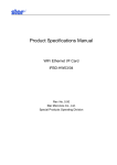
2. Configure IP
Router
The Router Configuration Menu contains the following
submenus and commands.
Routing
Main Menu
Configure RIP
version by port
All interfaces
configured with
IP?
Enable bridging
interface per port
Define IP for each
interface per port
Enable global
bridging
Using RIP?
Using default
route?
Enable RIP
globally
Add default route
to routing table
Add static route to
routing table
End
End
End
You must restart the PARTNER ACS 1600 DSL module for
any changes to take effect. For more information, see the
“PARTNER ACS 1600 DSL module basics” chapter.
Avaya, Inc.
- 30 - PARTNER ACS 1600 DSL module User Guide
C. Configure Port IP Address
Sets the IP address and subnet mask for the selected
interface.
Type the number of the Interface, the number of the port or
connection to configure, and then enter the following:
• New IP address
• New subnet mask
• Priority
The PARTNER ACS 1600 DSL module displays a default or
last-used value in parentheses to the left of the command
prompt. To accept this value, press ENTER.
U. Unconfigure Port IP Address
Deletes the IP address of the selected interface. Type the
number of the port to unconfigure, confirm, and then press
ENTER.
S. Add/Remove a Static Route
Displays the Router Modification Menu, which contains the
following commands:
A. Add a Static Route
Creates a static route and adds it to the Route Table.
Type the following information for the route you want to
add, and then press ENTER:
• Destination (IP) address
• Network mask
• Gateway
The PARTNER ACS 1600 DSL module displays a default or
last-used value in parentheses to the left of the command
prompt. To accept this value, press ENTER.
R. Remove a Route
Deletes a static route from the Route Table. Type the
IP address of the route to remove, and then press
ENTER.
F. Add/Change Default Route
Creates or changes the default static route, and then
adds it to the Route Table. Type the Gateway address
for the default route, and then press ENTER.
Avaya, Inc.
- 31 - PARTNER ACS 1600 DSL module User Guide
T. Remove the Default Route
Deletes the default static route from the Route Table.
Type the IP address to remove, and then press
ENTER.
D. Display Route Table
Displays the following information about statically
configured routes and dynamically learned ones:
• NETWORK
ADDRESS
destination
address.
• NETMASK - IP subnet mask; number of bits
reserved for the host ID.
• GATEWAY ADDRESS - IP address of
packets sent to destination.
• interface - IP address of outgoing interface.
• Metric - number of hops (routers) required to
reach the specified gateway.
• Type – static or dynamic.
R. Enable/Disable RIP
Enables and disables the Routing Information Protocol (RIP).
RIP sends routing information from one router to adjacent
routers, dynamically "learning" network topology.
When you enable RIP, the PARTNER ACS 1600 DSL module
stores sent routing information in the Route Table. For more
information on the Route Table, see "Reports Menu" earlier in
this chapter.
V. Configure RIP Version by Port
Sets the RIP version for the selected port.
Type the number of the Interface, the port number, and then
select one of the following RIP Versions:
0. Disabled
1. Version 1 Broadcast
2. Version 2 Broadcast
3. Version 2 Multicast
P. Configure RIP Poisoned Reverse by Port
Enables and disables RIP Poisoned Reverse for the selected
interface.
Type the number of the Interface, and then enable or disable.
Avaya, Inc.
- 32 - PARTNER ACS 1600 DSL module User Guide
N. Configure DNS Client
Displays the DNS Client Menu, which contains the following
commands to configure the Domain Name Server (DNS)
client:
A. Set DNS Server IP Address
Sets the IP address of the DNS Server. Type the DNS
Server IP address, and then press ENTER.
T. Set DNS Server Timeout
Sets the DNS Server Timeout, a value between 5 - 20
seconds (default = 5 seconds). Type the DNS Server
Timeout value, and then press ENTER.
S. Display DNS Cache and Statistics
Displays information about the data in the DNS cache.
H. Configure DHCP Client
Enables and disables the Dynamic Host Configuration
Protocol (DHCP) client for the selected Interface. Type the
number of the Interface, the number of the port, and then
enable or disable.
L. Configure DHCP Relay
Displays the DHCP Relay Menu, which contains the following
commands to configure the DHCP Relay:
E. Enable/Disable DHCP Relay
Enables and disables the DHCP Relay.
When you enable the DHCP Relay, you must also
enter a new DHCP server IP address. Type the DHCP
Server IP address, and then press ENTER.
The PARTNER ACS 1600 DSL module displays a
default or last-used value in parentheses to the left of
the command prompt. To accept this value, press
ENTER.
C. Configure DHCP Relay
Sets the DHCP server IP address. Type the DHCP
Server IP address, and then press ENTER.
The PARTNER ACS 1600 DSL module displays a
default or last-used value in parentheses to the left of
the command prompt. To accept this value, press
ENTER.
Avaya, Inc.
- 33 - PARTNER ACS 1600 DSL module User Guide
S. Display DHCP Relay Statistics
Displays the following information about the DHCP
Relay:
•
DHCP client requests forwarded to DHCP server
•
DHCP client requests dropped
•
Server responses forwarded to DHCP clients
•
Server responses dropped
•
Unknown server responses
•
Server requests timed out
T. Configure Telnet Server Port
Sets the port for the Telnet Server (default = 23).
Type the number of the port, and then press ENTER.
The PARTNER ACS 1600 DSL module displays a default or
last-used value in parentheses to the left of the command
prompt. To accept this value, press ENTER.
F. Configure IP Filtering
Displays the IP Filtering Configuration Menu, which
contains the following submenu and commands to configure
IP filtering. For more information, see the "IP Filtering"
appendix.
P. Choose port for IP filtering
Sets the port on which to use IP filtering.
Type the number of the interface, the number of the
port (if applicable), and then press ENTER.
F. Globally enable/disable input or output filters
Enables and disables the input and output filters for all
installed interfaces.
You must globally enable the filters for the associated
filtering to work.
Follow the on-screen instructions to enable or disable
both the input and output filters globally.
Avaya, Inc.
- 34 - PARTNER ACS 1600 DSL module User Guide
T. Toggle input or output type filters to view/edit
Switches between the input and output filter types.
The filter type that you set here determines what
displays when you select any of the following
commands:
• Display all filters of the chosen type
• Insert a new or buffered filter of the chosen
type
• Append a new or buffered filter to the end of
the list
• Edit filter of the chosen type
• Copy filter operations menu
• Delete one filter of the chosen type
• Delete all filters of the chosen type
D. Display all filters of the chosen type
Displays all filters of the type set with the Toggle input
or output type filters to view/edit command.
I. Insert a new or buffered filter of the chosen type
Adds a new filter of the type set with the Toggle input
or output type filters to view/edit command
anywhere in the list that displays when you select
Display all filters of the chosen type.
Type the number of the filter before which you want to
insert the new filter, and then follow the on-screen
messages to enter the following information:
• Filter state – Idle or Active
• Filter action – Pass or Discard
• Filter protocol – IP, ICMP, IGMP, TCP, UDP
• Filter Source IP Low Address
• Filter Source IP High Address
• Filter Source Port Low
• Filter Source Port High
• Filter Destination IP Low Address
• Filter Destination IP High Address
• Filter Destination Port Low
• Filter Destination Port High
The PARTNER ACS 1600 DSL module displays a
default or last-used value in parentheses to the left of
the command prompt. To accept this value, press
ENTER.
Avaya, Inc.
- 35 - PARTNER ACS 1600 DSL module User Guide
A. Append a new or buffered filter to the end of the
list
Adds a new filter of the type set with the Toggle input
or output type filters to view/edit command to the
end of list that displays when you select Display all
filters of the chosen type.
Type Y, and then follow the on-screen messages to
enter the following information:
• Filter state – Idle or Active
• Filter action – Pass or Discard
• Filter protocol – IP, ICMP, IGMP, TCP, UDP
• Filter Source IP Low Address
• Filter Source IP High Address
• Filter Source Port Low
• Filter Source Port High
• Filter Destination IP Low Address
• Filter Destination IP High Address
• Filter Destination Port Low
• Filter Destination Port High
The PARTNER ACS 1600 DSL module displays a
default or last-used value in parentheses to the left of
the command prompt. To accept this value, press
ENTER.
E. Edit filter of the chosen type
Displays all filters of the type that you set with the
Toggle input or output type filters to view/edit
command that you can edit.
Type the number of the filter to edit, and then follow the
on-screen messages to enter the following information:
• Filter state – Idle or Active
• Filter action – Pass or Discard
• Filter protocol – IP, ICMP, IGMP, TCP, UDP
• Filter Source IP Low Address
• Filter Source IP High Address
• Filter Source Port Low – TCP or UDP packets
only
• Filter Source Port High - TCP or UDP packets
only
• Filter Destination IP Low Address
• Filter Destination IP High Address
• Filter Destination Port Low
Avaya, Inc.
- 36 - PARTNER ACS 1600 DSL module User Guide
• Filter Destination Port High
The PARTNER ACS 1600 DSL module displays a
default or last-used value in parentheses to the left of
the command prompt. To accept this value, press
ENTER.
C. Copy filter operations menu
Displays the IP Filter Copy to Buffer Menu, which
contains the following commands for all filters of the
type that you set with the Toggle input or output type
filters to view/edit command.
C. Copy a filter of the chosen type to the
buffer
Copies the filter that you select to the buffer.
Type the number of the filter to copy, and then
press enter.
D. Display the filter in the copy buffer
Displays the following information about the filter
in the copy buffer:
• num – number of the filter
• state – Idle or Active
• action – Pass or Discard
• srcLwP - Filter Source Port Low – TCP
or UDP packets only
• srcHiP - Filter Source Port High - TCP or
UDP packets only
• source.ip.addr.low - Filter Destination
IP Low Address
• source.ip.addr.high - Filter Source IP
High Address
• proto - Filter protocol – IP, ICMP, IGMP,
TCP, UDP
• mask – ICMP or TCP only
• dstLwP - Filter Destination Port Low
• dstHiP - Filter Destination Port High
• dest.ip.addr.low - Filter Destination IP
Low Address
• dest.ip.addr.high - Filter Destination IP
High Address
Avaya, Inc.
- 37 - PARTNER ACS 1600 DSL module User Guide
E. Edit the filter in the copy buffer
Edits the filter in the copy buffer.
Follow the on-screen messages to enter the
following information:
• Filter state – Idle or Active
• Filter action – Pass or Discard
• Filter protocol – IP, ICMP, IGMP, TCP,
UDP
• Filter Source IP Low Address
• Filter Source IP High Address
• Filter Source Port Low – TCP or UDP
packets only
• Filter Source Port High - TCP or UDP
packets only
• Filter Destination IP Low Address
• Filter Destination IP High Address
• Filter Destination Port Low
• Filter Destination Port High
The PARTNER ACS 1600 DSL module displays
a default or last-used value in parentheses to
the left of the command prompt. To accept this
value, press ENTER.
X. Deletes the filter in the copy buffer
Deletes the filter in the copy buffer.
X. Delete one filter of the chosen type
Deletes the filter that you select from the copy buffer.
Type the number of the filter to delete and then press
ENTER.
Z. Delete all filters of the chosen type
Deletes all filters in the copy buffer.
S. Show IP filtering statistics
Displays the total number of input and output data
packets filtered.
Y. Clear IP filtering statistics
Deletes all data from the Show IP filtering statistics
command.
Avaya, Inc.
- 38 - PARTNER ACS 1600 DSL module User Guide
D. Display Route Table
Displays the following information about statically configured
routes and dynamically learned ones:
• NETWORK ADDRESS - destination address.
• NETMASK - IP subnet mask; number of bits
reserved for the host ID.
• GATEWAY ADDRESS - IP address of packets sent
to destination.
• interface - IP address of outgoing interface.
• Metric - number of hops (routers) required to reach
the specified gateway.
• Type – static or dynamic.
Avaya, Inc.
- 39 - PARTNER ACS 1600 DSL module User Guide
3. Configure
Bridge
Displays the Bridge Configuration Menu, which contains the
following submenu and commands.
Bridging
Main Menu
Enable bridging by
port
Enable bridging
globally
Enable spanning
tree by port
Using spanning
tree?
Enable spanning
tree globally
Assigning
bridge priority?
Define bridge
priority
Avaya, Inc.
Define root bridge
Assigning root
bridge?
End
End
- 40 - PARTNER ACS 1600 DSL module User Guide
Your settings display in the Display Current Configuration
command in the Reports Menu. For more information, see
"Reports Menu" earlier in this chapter.
You must enable bridging both globally and by port number,
and then restart the PARTNER ACS 1600 DSL module for
any changes to take effect.
For more information on
restarting the PARTNER ACS 1600 DSL module, see the
“PARTNER ACS 1600 DSL module basics” chapter.
G. Enable/Disable Bridging Globally
Enables and disables bridging for all installed interfaces.
P. Enable/Disable Bridging by Port
Enables and disables bridging by port.
Type the number of the Interface to enable or disable, and
then press ENTER.
A. Configure Bridge Aging Timer
Sets the bridge database aging time, a value between 1-3,600
seconds (default = 300 seconds). Type the bridge aging time
value, and then press ENTER.
The PARTNER ACS 1600 DSL module displays a default or
last-used value in parentheses to the left of the command
prompt. To accept this value, press ENTER.
The time counts down in one-second intervals; at zero, the
entry deletes from the database.
T. Enable/Disable Spanning Tree Globally
Enables and disables the Spanning Tree protocol for all
installed interfaces.
O. Enable/Disable Spanning Tree by Port
Enables and disables the Spanning Tree protocol for the
selected Interface.
Type the number of the Interface, and then select enable or
disable.
R. Configure Spanning Tree Bridge Priority
Sets the Spanning Tree bridge priority, a value between 165,565 (default = 32,768). Type the Spanning Tree bridge
priority value, and then press ENTER.
The PARTNER ACS 1600 DSL module displays a default or
last-used value in parentheses to the left of the command
prompt. To accept this value, press ENTER.
Avaya, Inc.
- 41 - PARTNER ACS 1600 DSL module User Guide
The Spanning Tree algorithm selects the bridge with the
lowest priority on the network as the Root Bridge.
Q. Configure Spanning Tree Port Priority
Sets the Spanning Tree priority by port, a value between 0255 (default = 128). The lower the value, the higher the
priority.
Type the number of the Interface to configure, the port priority
value, and then press ENTER.
The PARTNER ACS 1600 DSL module displays a default or
last-used value in parentheses to the left of the command
prompt. To accept this value, press ENTER.
The spanning tree algorithm uses the spanning tree bridge
priority to determine which bridge to use as the Ethernet LAN
destination when two or more bridges are bridging between
the same LAN.
H. Configure Spanning Tree Hello Time
Sets the Spanning Tree hello time, a value between 1-10
seconds (default = 2 seconds). Type the hello time value, and
then press ENTER.
The PARTNER ACS 1600 DSL module displays a default or
last-used value in parentheses to the left of the command
prompt. To accept this value, press ENTER.
S. Configure Spanning Tree Max Age
Sets the Spanning Tree max age, a value between 6-40
seconds (default = 20 seconds). Type the max age value,
and then press ENTER.
The PARTNER ACS 1600 DSL module displays a default or
last-used value in parentheses to the left of the command
prompt. To accept this value, press ENTER.
F. Configure Spanning Tree Forward Delay
Sets the Spanning Tree forward delay, a value between 4-30
seconds (default = 15 seconds). Type the forward delay
value, and then press ENTER.
The PARTNER ACS 1600 DSL module displays a default or
last-used value in parentheses to the left of the command
prompt. To accept this value, press ENTER.
C. Configure Spanning Tree Path Cost
Sets the Spanning Tree path cost, a value between 1- 65,535
(default = 32,768).
Type the number of the Interface to configure, type the path
cost value, and then press ENTER.
Avaya, Inc.
- 42 - PARTNER ACS 1600 DSL module User Guide
The PARTNER ACS 1600 DSL module displays a default or
last-used value in parentheses to the left of the command
prompt. To accept this value, press ENTER.
When there are multiple paths to the Root Bridge, the
Spanning Tree algorithm selects the port with the lowest total
path cost as the route port.
D. Delete Bridge Forwarding Database Entry
Deletes an Ethernet address from the bridge forwarding
database. Type the Ethernet address to delete, and then
press ENTER.
Avaya, Inc.
- 43 - PARTNER ACS 1600 DSL module User Guide
5. Configure
WAN
Displays the WAN Configuration Menu, which contains the
following submenu and commands. Commands may or may
not display, depending on the datalink protocol that you select
and the Interface installed.
SDSL WAN
configuration
SDSL Module
Changing
factory
configuration?
Select quick
configuration
ATM?
Define PVCs
ATM?
Frame Relay?
Configure ATM
options
Define PVCs
Frame Relay?
Define DLCIs
Configure ATM
options
Define DLCIs
End
Set maintenance
protocol
End
Set maintenance
protocol
End
End
Avaya, Inc.
- 44 - PARTNER ACS 1600 DSL module User Guide
0. Quick Configuration
Displays the Quick Configuration submenu, which contains
the following commands to quickly configure the NetEngine
PARTNER ACS 1600 DSL module .
1. Lucent Stinger (Conexant Autobaud, Payload
Scrambling)
2. Nokia (Auto Cycle)
3. Copper Mountain (Auto Sense)
4. Paradyne (Framed 784Kbps, Payload
Scrambling)
5. AccessLan CPE
6. Nortel IMAS
7. ATM (Unframed, 1152Kpbs fixed)
8. Frame Relay (784Kpbs fixed)
Select your choice.
The PARTNER ACS 1600 DSL module for any changes to
take effect. For more information on restarting the PARTNER
ACS 1600 DSL module, see the “PARTNER ACS 1600 DSL
module basics” chapter.
1. Configure Datalink Protocol
Displays the WAN Datalink Protocol Configuration Menu,
which contains the following commands to set the data link
control protocol for the active interface.
1. Lucent Stinger (Conexant Autobaud, Payload
Scrambling)
2. Nokia (Auto Cycle)
3. Copper Mountain (Auto Sense)
4. Paradyne (Framed 784Kbps, Payload
Scrambling)
5. AccessLan CPE
6. ATM
7. Frame Relay
Select your choice.
The IAD automatically restarts.
Your settings display in the Display Current Configuration
command in the Reports Menu. For more information, see
"Reports Menu" earlier in this chapter.
Avaya, Inc.
- 45 - PARTNER ACS 1600 DSL module User Guide
2. Configure Physical Interface
Configure Physical Interface submenus and commands
may or may not display, depending on the Interface that you
select.
Universal Serial Interface (USI) Mode
Displays USI Configuration Menu, which contains the
following commands:
1. Set WAN interface type
Displays the USI Interface Type submenu, which contains
the following commands that set the electrical configuration
for the USI WAN mode.
1. RS-530
2. V.35
Select your choice.
2. Configure Data Rate and Clocking Options
Displays the Serial Interface Clock Speed Option Menu,
which contains the following commands to set the receive
clock speed:
1. Track USI speed to SDSL speed
2. Set Clock Speed Manually
Displays the USI Datarate submenu, which contains
the following commands that set the electrical
configuration for the USI WAN mode.
1. Externally provided
2. 5.0 MBps
3. 2.083 MBps
4. 1.562 MBps
5. 520 KBps
6. 112 KBps
Select your choice.
3. Use Internal Receive Clock
4. Use External Receive Clock
Select your choice.
Avaya, Inc.
- 46 - PARTNER ACS 1600 DSL module User Guide
SDSL Mode
Displays SDSL Configuration submenu, which contains the
following commands to set the SDSL mode or speed.
The PARTNER ACS 1600 DSL module displays a default or
last-used value in parentheses to the left of the command
prompt. To accept this value, press ENTER.
1. Toggle SDSL Mode (CO or CPE)
2. Set SDSL Speed to Auto Cycle (Nokia)
Displays the Auto Cycle First Speed Option
submenu, which contains the following commands to
set the initial speed.
1. 1536 Kbps
2. 1152 Kbps
3. 768 Kbps
4. 384 Kbps
5. 192 Kbps
Select your choice.
3. Set SDSL Speed to Auto Sense (Copper
Mountain)
4. Enable/Disable Conexant AutoBaud Mode
Enables and disables the Conexant AutoBaud rate
adaptation mode.
5. Set SDSL Sync Delay (Lucent)
Sets the SDSL sync delay. Follow the on-screen
messages to disable AutoBaud. You must disable
AutoBaud to set the SDSL sync delay.
6. Set SDSL to AccessLan CPE Mode
7. Set SDSL Speed Manually
Sets the SDSL speed, a value between 144-2,320
Kbps. Type the SDSL data rate value, and then press
ENTER.
8. Restart SDSL Activation Sequence
9. SDSL Interface Mode (Bit Order)
A. Enable/Disable SDSL
AutoBaud Debug
Messages
Enables and disables the display of SDSL AutoBaud
debugging messages. Select to enable. Select a
second time to disable.
Avaya, Inc.
- 47 - PARTNER ACS 1600 DSL module User Guide
D. Enable/Disable SDSL Debug Messages
Enables and disables the display of SDSL debugging
messages. Select to enable. Select a second time to
disable.
Y. Enable/Disable Sync Msgs
Enables and disables the display of configuration
synchronization messages. Select to enable. Select a
second time to disable.
P. Preactivation Debug Mode
Enables and disables the preactivation debug
messages. Select to enable. Select a second time to
disable.
Select your choice.
3. Configure DLCIS (Frame Relay)
Displays the FR DLCI Config Menu, which contains the
following commands to set the current DLCI value.
1. Add New DLCI
Type the DLCI number, press ENTER, and then
choose a command from the FR Encapsulation
Configuration submenu.
1. RAW (No Encapsulation)
2. Proprietary Voice DLCI
3. RFC 1490
4. ATM RFC 1483 (Tunneling)
Select your choice, and then choose a command from
the FR DLCI Options submenu.
1. Configure Transmit CIR
Follow the on-screen messages to enter the
following information.
Questions below may or not display, depending
on the options that you select.
• Transmit Committed Information Rate
(CIR)
• Committed burst size (Bc)
• Circuit Throughput
• Excess burst size (Be)
The PARTNER ACS 1600 DSL module displays
a default or last-used value in parentheses to
the left of the command prompt. To accept this
value, press ENTER.
Avaya, Inc.
- 48 - PARTNER ACS 1600 DSL module User Guide
2. Configure Receive CIR
Follow the on-screen messages to enter the
following information. Questions below may or
not display, depending on the options that you
select.
• Receive Committed Information Rate
(CIR)
• Committed burst size (Bc)
• Circuit Throughput
• Excess burst size (Be)
The PARTNER ACS 1600 DSL module displays
a default or last-used value in parentheses to
the left of the command prompt. To accept this
value, press ENTER.
3. Configure FRF.12 Fragmentation
Displays the End-to-End Fragmentation
Configuration submenu, which contains the
following commands.
1. Enable/Disable End-to-End FRF.12
Enables
and
disables
End-to-End
FRF.12.
2. Set Fragmentation Size
Sets the maximum fragmentation size, a
value between 100-1,600 bytes.
Type the fragmentation size, and then
press ENTER.
The PARTNER ACS 1600 DSL module displays
a default or last-used value in parentheses to
the left of the command prompt. To accept this
value, press ENTER.
Select your choice.
Avaya, Inc.
- 49 - PARTNER ACS 1600 DSL module User Guide
2. Modify Existing DLCI
Type the DLCI number, press ENTER, and then
choose a command from the FR Encapsulation
Configuration submenu.
1. RAW (No Encapsulation)
2. Proprietary Voice DLCI
3. RFC 1490
4. ATM RFC 1483 (Tunneling)
Select your choice, and then choose a command from
the FR DLCI Options submenu.
1. Configure Transmit CIR
Follow the on-screen messages to enter the
following information.
Questions below may or not display, depending
on the options that you select.
• Transmit Committed Information Rate
(CIR)
• Committed burst size (Bc)
• Circuit Throughput
• Excess burst size (Be)
The PARTNER ACS 1600 DSL module displays
a default or last-used value in parentheses to
the left of the command prompt. To accept this
value, press ENTER.
2. Configure Receive CIR
Follow the on-screen messages to enter the
following information. Questions below may or
not display, depending on the options that you
select.
• Receive Committed Information Rate
(CIR)
• Committed burst size (Bc)
• Circuit Throughput
• Excess burst size (Be)
The PARTNER ACS 1600 DSL module displays
a default or last-used value in parentheses to
the left of the command prompt. To accept this
value, press ENTER.
Avaya, Inc.
- 50 - PARTNER ACS 1600 DSL module User Guide
3. Configure FRF.12 Fragmentation
Displays the End-to-End Fragmentation
Configuration submenu, which contains the
following commands.
1. Enable/Disable End-to-End FRF.12
Enables
and
disables
End-to-End
FRF.12.
2. Set Fragmentation Size
Sets the maximum fragmentation size, a
value between 100-1,600 bytes.
Type the fragmentation size, and then
press ENTER.
The PARTNER ACS 1600 DSL module displays
a default or last-used value in parentheses to
the left of the command prompt. To accept this
value, press ENTER.
Select your choice.
3. Delete DLCI
Type the number of the port to delete, and then press ENTER.
4. Show Current DLCIs
Displays encapsulation information about the active DLCI
values on per port basis.
You must restart the PARTNER ACS 1600 DSL module for
any changes to take effect.
For more information on
restarting the PARTNER ACS 1600 DSL module, see the
“PARTNER ACS 1600 DSL module basics” chapter.
3. Configure PVCS (ATM)
Displays the ATM PVC Config Menu, which contains the
following commands to set the current Permanent Virtual
Circuit (PVC) Virtual Port Identifier (VPI) and Virtual Circuit
Identifier (VCI) values by port:
1. Add New PVC
Type the VPI, the VCI, and then choose a command from the
ATM Encapsulation Configuration submenu.
1. AAL5 (None)
Displays the ATM Service Category Configuration
submenu, which contains the following commands to
set the service category:
1. CBR
2. UBR
Select your choice, and then follow the on-screen
messages to set the Peak Cell Rate (PCR) value.
Avaya, Inc.
- 51 - PARTNER ACS 1600 DSL module User Guide
2. AAL0 (None)
Displays the ATM Service Category Configuration
submenu, which contains the following commands to
set the service category:
1. CBR
2. UBR
Select your choice, and then follow the on-screen
messages to set the PCR value.
3. Proprietary Voice
Select for Voice encapsulation over a specific PVC.
4. RFC 1483 (using VC Muxing)
Displays the ATM Service Category Configuration
submenu, which contains the following commands to
set the service category:
1. CBR
2. UBR
Select your choice, and then follow the on-screen
messages to set the PCR value.
This options supports either routing or bridging, but not
both.
5. RFC 1483 (with LLC Encapsulation)
Displays the ATM Service Category Configuration
submenu, which contains the following commands to
set the service category:
1. CBR
2. UBR
Select your choice, and then follow the on-screen
messages to set the PCR value.
6. RFC 2364 (PPPoATM with LLC Encapsulation)
Displays the following commands to set the PPP
authorization type:
0. None
1. PAP Client
2. PAP Server
3. CHAP Client
4. CHAP Server
Select your choice, and then follow the on-screen
messages to enter the following:
• New PPP Userid
• New PPP Password
• New CHAP Peer Name
Avaya, Inc.
- 52 - PARTNER ACS 1600 DSL module User Guide
Displays the ATM Service Category Configuration
submenu, which contains the following commands to
set the service category:
1. CBR
2. UBR
Select your choice, and then follow the on-screen
messages to set the PCR value.
7. RFC 2364 (PPPoATM using VC Muxing)
Displays the following commands to set the PPP
authorization type:
0. None
1. PAP Client
2. PAP Server
3. CHAP Client
4. CHAP Server
Select your choice, and then follow the on-screen
messages to enter the following:
• New PPP Userid
• New PPP Password
• New CHAP Peer Name
Displays the ATM Service Category Configuration
submenu, which contains the following commands to
set the service category:
1. CBR
2. UBR
Select your choice, and then follow the on-screen
messages to set the PCR value.
2. Modify Existing PVC
Type the virtual port identifier (VPI), the virtual circuit identifier
(VCI) and then choose a command from the ATM
Encapsulation Configuration submenu.
1. RAW (AAL5)
Displays the ATM Service Category Configuration
submenu, which contains the following commands to
set the service category:
1. CBR
2. UBR
Select your choice, and then follow the on-screen
messages to set the PCR value.
Avaya, Inc.
- 53 - PARTNER ACS 1600 DSL module User Guide
2. RAW (AAL0)
Displays the ATM Service Category Configuration
submenu, which contains the following commands to
set the service category:
1. CBR
2. UBR
Select your choice, and then follow the on-screen
messages to set the PCR value.
3. Proprietary Voice
Select for Voice encapsulation over a specific PVC.
4. RFC 1483 (using VC Muxing)
Displays the ATM Service Category Configuration
submenu, which contains the following commands to
set the service category:
1. CBR
2. UBR
Select your choice, and then follow the on-screen
messages to set the PCR value.
This option supports either routing or bridging, but not
both.
5. RFC 1483 (with LLC Encapsulation)
Displays the ATM Service Category Configuration
submenu, which contains the following commands to
set the service category:
1. CBR
2. UBR
Select your choice, and then follow the on-screen
messages to set the PCR value.
6. RFC 2364 (PPPoATM with LLC Encapsulation)
Displays the following commands to set the PPP
authorization type:
0. None
1. PAP Client
2. PAP Server
3. CHAP Client
4. CHAP Server
Select your choice, and then follow the on-screen
messages to enter the following:
• New PPP Userid
• New PPP Password
• New CHAP Peer Name
Avaya, Inc.
- 54 - PARTNER ACS 1600 DSL module User Guide
Displays the ATM Service Category Configuration
submenu, which contains the following commands to
set the service category:
1. CBR
2. UBR
Select your choice, and then follow the onscreen messages to set the PCR value.
7. RFC 2364 (PPPoATM using VC Muxing)
Displays the ATM Service Category Configuration
submenu, which contains the following commands to
set the service category:
1. CBR
2. UBR
Select your choice, and then follow the on-screen
messages to set the PCR value.
3. Delete PVC
Type the number of the port to delete, and then press ENTER.
4. Show Current PVCs
Displays statistical information about the active PVC values
on per port basis.
You must restart the PARTNER ACS 1600 DSL module for
any changes to take effect.
For more information on
restarting the PARTNER ACS 1600 DSL module, see the
“PARTNER ACS 1600 DSL module basics” chapter.
4. Configure FR Options (Frame Relay)
Displays the Frame Relay Options submenu, which contains
the following commands to set the Frame Relay options
1. Configure Fragmentation
Displays the FR Fragmentation Configuration submenu,
which contains the following commands to configure
fragmentation.
1. Configure FRF.12 Fragmentation
Displays the FR FRF.12 Configuration submenu,
which contains the following commands.
1. Enable/Disable FRF.12
Enables and disables FRF.12 fragmentation.
2. Enable Automatic Fragment Sizing
3. Set Manual Fragment Size
Sets the maximum fragment size, a value
between 0-50 ms or 100-1600 bytes.
Type the fragment size, and then press ENTER.
Avaya, Inc.
- 55 - PARTNER ACS 1600 DSL module User Guide
The PARTNER ACS 1600 DSL module displays a
default or last-used value in parentheses to the left of
the command prompt. To accept this value, press
ENTER.
2. Configure Copper Mountain Fragmentation
Displays the FR FRF.12 Configuration submenu,
which contains the following commands.
1. Enable/Disable CuMtn Fragmentation
Enables and disables Copper Mountain
fragmentation.
2. Set Real-Time DLCI
Sets a real time value for a DLCI port.
Type the number of the port, and then press
ENTER.
2. Configure Maintenance Protocol
Displays the Frame Relay Maintenance Protocol submenu,
which contains the following commands to set the Frame
Relay maintenance protocol:
0. None
1. CCITT Q.933 Annex a Network
2. CCITT Q.933 Annex a User
3. CCITT Q.933 Annex a Both
4. ANSI T1.617 Annex D Network
5. ANSI T1.617 Annex D User
6. ANSI T1.617 Annex D Both
7. LMI Network (FRF.1.1)
8. LMI User (FRF.1.1)
9. LMI Both (FRF.1.1)
Select your choice.
3. Configure Congestion Parameters
Displays the FR Congestion Configuration submenu, which
contains the following commands to configure fragmentation.
1. Configure Transmit Congestion Parameters
Follow the on-screen messages to enter the following
transmit congestion parameter information.
• FECN/BECN condition set size
• FECN/BECN condition clear size
• FECN/BECN maximum number of bytes to store
Avaya, Inc.
- 56 - PARTNER ACS 1600 DSL module User Guide
2. Configure Receive Congestion Parameters
Follow the on-screen messages to enter the following
receive congestion parameter information.
• FECN/BECN condition set size
• FECN/BECN condition clear size
• FECN/BECN maximum number of bytes to store
Select your choice.
Your settings display in the Display Current Configuration
command in the Reports Menu. For more information, see
"Reports Menu" earlier in this chapter.
You must restart the PARTNER ACS 1600 DSL module for
any changes to take effect.
For more information on
restarting the PARTNER ACS 1600 DSL module, see the
“PARTNER ACS 1600 DSL module basics” chapter.
4. Configure ATM Options (ATM)
Displays the ATM Configuration Menu, which contains the
following submenus and commands to configure the ATM
options.
1. Configure Payload Scrambling
Enables and disables payload scrambling.
2. Configure F4 OAM VPI
Sets the F4 OAM VPI value, a value between 0 and
255. Type the VPI value, and then press ENTER.
The VPI value must match the VPI from a currently
configured PVC.
3. Configure F4 OAM Type
Displays the F4 OAM Type Configuration Menu,
which contains the following options to set the F4 OAM
type.
0. None
4. F4 End to end OAM
Select your choice.
4. Display F4 OAM Configuration
Displays the F4 OAM type.
5. Send OAM Loopback
Sends an OAM Loopback cell on the port that you
select.
6. Configure EmptyCells
Configures any empty cells. Type 1 to configure idle
cells or 2 to configure unassigned cells.
Avaya, Inc.
- 57 - PARTNER ACS 1600 DSL module User Guide
You must restart the PARTNER ACS 1600 DSL module for
any changes to take effect.
For more information on
restarting the PARTNER ACS 1600 DSL module, see the
“PARTNER ACS 1600 DSL module basics” chapter.
6. Configure
LAN
Displays the LAN Configuration Menu, which contains the
following command:
F. Set/Clear Full Duplex
Enables and disables full duplex Ethernet mode, which allows
simultaneous transmission and receipt of Ethernet packets.
Type the number of the port, select enable or disable, and
then press ENTER.
Your settings display in the Display Current Configuration
command in the Reports Menu. For more information, see
"Reports Menu" earlier in this chapter.
7. Configure
SNMP
Displays the SNMP Configuration Menu, which contains the
following commands to configure the simple network
management protocol (SNMP):
E. Enable/Disable SNMP
Enables and disables SNMP.
P. Configure System Contact
Sets the name of the SNMP contact person (maximum = 39
alphanumeric characters). Type the new system contact
information, and then press ENTER.
N. Configure System Name
Sets the name of the SNMP host server (maximum = 39
alphanumeric characters). Type the descriptive information,
and then press ENTER.
L. Configure System Location
Sets the location of the SNMP host server (maximum = 39
alphanumeric characters). Type the new location information,
and then press ENTER.
Avaya, Inc.
- 58 - PARTNER ACS 1600 DSL module User Guide
C. Configure SNMP Community
Sets the SNMP community to which your device belongs
(maximum = 39 alphanumeric characters). This name must
match the name of the SNMP host. Type the name, and then
press ENTER.
If SNMP you enable and the Community Name is null, SNMP
goes into read-only mode.
T. Configure SNMP Trap Host IP Address
Sets the IP address of the system setup for trap operations.
Type the IP address, and then press ENTER.
8. Configure
Login
Displays the Password Configuration Menu, which contains
the following commands to set the default User ID and the
default User and Network Administrator passwords:
You must restart the PARTNER ACS 1600 DSL module for
any changes to take effect.
For more information on
restarting the PARTNER ACS 1600 DSL module, see the
“PARTNER ACS 1600 DSL module basics” chapter.
1. Change User ID
Changes the default User ID. Type the new User ID
(maximum 17 alphanumeric characters), and then press
ENTER.
2. Change User Password
Changes the default User password. Type the new password
(maximum 17 alphanumeric characters), and then press
ENTER. Retype the new password, and then press ENTER.
3. Change NetMan Password
Changes the default Network Administrator password. Type
the new password (maximum 17 alphanumeric characters),
and then press ENTER. Retype the User password, and then
press ENTER.
For more information on changing the User ID or password,
see the "Administration" chapter.
Avaya, Inc.
- 59 - PARTNER ACS 1600 DSL module User Guide
9. System
Utilities
Displays the Utilities Menu, which contains the following
submenus and commands that either upgrade the ACOS
software or support ACOS application development.
Except for Ping Utility and Trace Route, these commands
are only for application development, software upgrades or to
restore factory defaults.
You must restart the PARTNER ACS 1600 DSL module for
any changes to take effect.
For more information on
restarting the PARTNER ACS 1600 DSL module, see the
“PARTNER ACS 1600 DSL module basics” chapter.
P. Ping Utility
Uses the Ping protocol to check for the presence of a host on
the Internet.
Type the following information, and then press ENTER:
• IP address or complete host name to Ping**
• Ping packet size
• Number of times to Ping
** You must enter the domain name with the host name. For
example, mycomputer.mydomain.com.
The PARTNER ACS 1600 DSL module displays a default or
last-used value in parentheses to the left of the command
prompt. To accept this value, press ENTER.
T. Trace Route
Traces the route to a specific host.
Enter the IP address or host name** to trace, and then press
ENTER.
** You must enter the domain name with the host name. For
example, mycomputer.mydomain.com.
The PARTNER ACS 1600 DSL module displays a default or
last-used value in parentheses to the left of the command
prompt. To accept this value, press ENTER.
Avaya, Inc.
- 60 - PARTNER ACS 1600 DSL module User Guide
Z. Configure Console Baud Rate
Displays the following commands to set the console Baud
rate:
0. Unset (use Default)
1. 9600
2. 19200
3. 38400
4. 57600
5. 115200
Select your choice.
V. Configure Console Timeout
Sets the console timeout, a value between 0-60 minutes
(default = 3 minutes). Type the timeout value, and then press
ENTER.
The PARTNER ACS 1600 DSL module displays a default or
last-used value in parentheses to the left of the command
prompt. To accept this value, press ENTER.
R. Hard Reset or Reload ACOS from FLASH
Restarts the PARTNER ACS 1600 DSL module using all
values set during the active session and reloads ACOS from
FLASH memory. For more information, see the “PARTNER
ACS 1600 DSL module basics” chapter.
D. Set System Defaults
Switches to the factory default configuration.
W. Save System Settings as Defaults
Saves the current system settings as the default configuration.
F. File System Menu
Displays the File System Menu, which contains the following
commands that support ACOS application development.
D. Directory of all Files
Displays a list of all files stored in Flash memory in the
PARTNER ACS 1600 DSL module.
C. Copy file
Copies and saves the entered file under a new file
name. Type the name of the file to copy, and then type
the new file name.
Avaya, Inc.
- 61 - PARTNER ACS 1600 DSL module User Guide
R. Rename File
Replaces the old file name with a new one. Type the
old file name, and then type the new one.
X. Remove File by name
Deletes the entered file from the file system.
F. Format File System drive
Deletes all files in the file system, including the
configuration file (config.st).
If you delete the configuration file, you will have to
reconfigure every setting.
S. Space left in File System
Displays the available disk space (bytes) in the file
system.
X. File Transfer Menu
Displays the File Transfer Menu, which contains the following
commands to transfer files on to the PARTNER ACS 1600
DSL module.
B. Load Boot ROM
Displays the File Transfer Method submenu, which
contains the following commands that download the
Boot ROM to the file system stored in Flash memory in
the PARTNER ACS 1600 DSL module:
1. Receive via TFTP
2. Receive via XMODEM
Select your choice.
O. Update ACOS [acos.bin]
Displays the File Transfer Method submenu, which
contains the following commands that download
Polycom’s Atlas Communications Operating System
(ACOS) to the file system stored in Flash memory in
the PARTNER ACS 1600 DSL module:
1. Receive via TFTP
2. Receive via XMODEM
Select your choice.
Type the IP address of the computer that has a TFTP
server, and then type the name of the file to download.
Avaya, Inc.
- 62 - PARTNER ACS 1600 DSL module User Guide
You must restart the PARTNER ACS 1600 DSL
module to load the new version of ACOS. For more
information on restarting the PARTNER ACS 1600 DSL
module or on upgrading your software using TFTP, see
the “PARTNER ACS 1600 DSL module basics”
chapter.
X. Update Entire System
Uses TFTP to download files to update the IAD.
A. File Transfer Utilities
Displays the File Transfer Method submenu,
which contains the following commands that
download a file to the file system stored in Flash
memory in the PARTNER ACS 1600 DSL
module:
1. Receive via TFTP
2. Send or Receive via XMODEM
Select your choice.
I. Interworking
Connections
Displays the Connections Menu, which contains the
following commands. This menu only displays when an USI
Interface is installed.
You must restart the PARTNER ACS 1600 DSL module for
any changes to take effect. For more information the
PARTNER ACS 1600 DSL module, see the “PARTNER ACS
1600 DSL module basics” chapter.
1. Add Interworking Connection
Follow the on-screen messages to create an interworking
connection.
Questions below may or not display, depending on the options
that you select.
• Type the number of the NIM with the datalink protocol =
Frame Relay.
• Select the port to use.
• Type the number of the NIM with the datalink protocol =
ATM.
• Select the port to use.
Avaya, Inc.
- 63 - PARTNER ACS 1600 DSL module User Guide
The Available interworking types menu displays, which
contains the following commands and submenus that create a
Frame Relay to ATM Interworking connection:
1. FRF5
Displays the FRF.5 DE Mapping submenu, which contains
the following commands to set how the DE maps to the CLPI:
0. Set FR-SSCS, ATM = 0
Displays the FRF.5 CLPI Mapping menu, which
contains the following commands to set FR-SSCS:
A. Set FR-SSCS according to ATM
B. Use both FR-SSCS and ATM
1. Set FR-SSCS, ATM = 1
Displays the FRF.5 CLPI Mapping menu, which
contains the following commands to set FR-SSCS:
A. Set FR-SSCS according to ATM
B. Use both FR-SSCS and ATM
B. Use both FR-SSCS and ATM
Displays the FRF.5 CLPI Mapping menu, which
contains the following commands to set FR-SSCS:
A. Set FR-SSCS according to ATM
B. Use both FR-SSCS and ATM
2. FRF8
Displays the FRF.8 Translation submenu, which contains the
following commands to set the FRF.8 translation parameters:
T. True
Displays the FRF.8 DE Mapping menu, which contains
the following commands to set the mapping value:
0. Always 0
Displays the FRF.8 FECN Mapping menu,
which contains the following commands to set
the FECN mapping value:
0. Always 0
1. Always 1
M. Map FR FECN to ATM EFCI
1. Always 1
Displays the FRF.8 FECN Mapping menu,
which contains the following commands to set
the FECN mapping value:
0. Always 0
1. Always 1
M. Map FR FECN to ATM EFCI
Avaya, Inc.
- 64 - PARTNER ACS 1600 DSL module User Guide
M. Map FR FECN to ATM EFCI
Displays the FRF.8 FECN Mapping menu,
which contains the following commands to set
the FECN mapping value:
0. Always 0
1. Always 1
M. Map FR FECN to ATM EFCI
F. False
Displays the FRF.8 DE Mapping menu, which contains
the following commands to set the DE mapping value:
0. Always 0
Displays the FRF.8 FECN Mapping menu,
which contains the following commands to set
the FECN mapping value:
0. Always 0
1. Always 1
M. Map FR FECN to ATM EFCI
1. Always 1
Displays the FRF.8 FECN Mapping menu,
which contains the following commands to set
the FECN mapping value:
0. Always 0
1. Always 1
M. Map FR FECN to ATM EFCI
M. Map FR DE to ATM CLPI
Displays the FRF.8 FECN Mapping menu,
which contains the following commands to set
the FECN mapping value:
0. Always 0
1. Always 1
M. Map FR FECN to ATM EFCI
2. Delete Interworking Connection
Deletes the selected interworking connection. Type the
number of the connection to delete, and then press ENTER.
3. Print Interworking Connections
Displays the following information about all active interworking
connections:
• ID - ID number for the interface.
• Type - FRF.5 or FRF.8.
• FR Slot - frame relay for this ID.
• DLCI - the frame relay datalink connection identifier.
Avaya, Inc.
- 65 - PARTNER ACS 1600 DSL module User Guide
•
•
•
ATM Slot - ATM slot number for this ID.
VPI - the ATM virtual path identifier (VPI) for this ID.
VCI - the virtual circuit identifier (VCI) for this ID.
For more information about a connection, type the ID number,
and then press ENTER.
4. Default Interworking Connections
Restores the default interworking connections.
D. Configure
DHCP Server
Displays the DHCP Server Configuration Menu, which
contains the following commands to configure DHCP.
DHCP dynamically assigns an IP address to all devices
connected to the PARTNER ACS 1600 DSL module. You
must select the Ethernet Interface to correctly use the
following commands.
You must restart the PARTNER ACS 1600 DSL module for
the changes to take effect. For more information on restarting
the PARTNER ACS 1600 DSL module or on upgrading your
software using TFTP, see the “PARTNER ACS 1600 DSL
module basics” chapter.
E. Enable/Disable DHCP
Enables and disables DHCP.
B. Enable/Disable DHCP Debug Messages
For factory use only.
I. Configure DHCP Server Parameters
Sets the DHCP server parameters.
Type the number of the Interface, the number of the port, the
following information, and then press ENTER:
• Gateway IP address
• DNS Server IP address
• NetBIOS Server IP address
• Subnet Mask
• Domain Name
• DHCP Lease Time
Avaya, Inc.
- 66 - PARTNER ACS 1600 DSL module User Guide
The NetBIOS Type Configuration Menu displays, which
contains the following commands to set the NetBIOS node
type:
1. B-node
2. P-node
4. M-node
8. H-node
Select your choice.
The PARTNER ACS 1600 DSL module displays a default or
last-used value in parentheses to the left of the command
prompt. To accept this value, press ENTER.
Your settings display in the Display DHCP Configuration
command.
P. Configure DHCP Address Range Pool
Sets the DHCP IP address range.
Type the high IP address, the low IP address, and then press
ENTER. Both IP addresses must be on the same Subnet
mask.
The PARTNER ACS 1600 DSL module displays a default or
last-used value in parentheses to the left of the command
prompt. To accept this value, press ENTER.
C. Configure DHCP Client Entry
Assigns the same IP address every time to the client that you
enter.
Type the following information, and then press ENTER:
•
•
Client entry number
DHCP Client MAC address (enter value without
colons)
• Host Name
• Lease Time
• IP Address
• Subnet Mask
• Default Gateway
• DNS Server
Your settings display in the Display DHCP Entry Details
command.
Avaya, Inc.
- 67 - PARTNER ACS 1600 DSL module User Guide
F. Display DHCP Configuration
Displays the following information about the DHCP
configuration:
• Default gateway - IP address of packets sent to
DHCP Clients.
• Default DNS server - IP address of the DNS
server.
• Default NetBIOS server - IP address of the
NetBIOS server.
• Node type - NetBIOS nodes type: B-node, P-node,
M-node or H-node.
• Default subnet - IP subnet mask; number of bits
reserved for the host ID.
• Default lease - length of time to keep the Internet
connection active.
• Domain name - defines the entity that owns the IP
address. For example, avaya.com.
• Low address - minimum IP address to assign.
• High address - maximum IP address to assign.
• Client Number - client entry number.
• Host name - name of the host.
• IP address - IP address of outgoing interface.
• Subnet mask - IP subnet mask; number of bits
reserved for the host ID.
• Lease time - length of time to keep the Internet
connection active.
• Gateway - IP address of packets sent to
destination.
• DNS Server - IP address of the DNS server.
S. Display DHCP Server Statistics
Displays the following information about the DHCP Server.
•
•
•
•
•
•
•
•
Avaya, Inc.
plain bootp requests received
plain bootp replys sent
discover packets sent
offer packets sent
dhcp request packets received
declines received
releases received
acks sent
- 68 - PARTNER ACS 1600 DSL module User Guide
•
•
•
nacks sent
requests for other servers
protocol errors
For the preceding to display, you must attach DHCP Client
devices that use DHCP to obtain an IP address to the
PARTNER ACS 1600 DSL module.
A. Display DHCP Server Assigned Addresses
Displays the following information about the DHCP Server
assigned addresses.
• IP - IP address of the device, assigned by the
PARTNER ACS 1600 DSL module.
• Client ID - Ethernet MAC address for the device.
• Status - how the IP address is assigned to the
device: through DHCP or manually.
For the preceding to display, you must attach DHCP Client
devices that use DHCP to obtain an IP address to the
PARTNER ACS 1600 DSL module.
D. Display DHCP Entry Details
Displays the following information about the DHCP entries.
•
•
•
•
•
•
•
•
•
IP address - IP address of the device.
Client ID - Ethernet MAC address for the device.
Status - how the IP address is assigned to the
device: through DHCP or manually.
Subnet - IP subnet mask; number of bits reserved
for the host ID.
Gateway - IP address of packets sent to
destination.
DNS - IP address of the DNS server.
Lease - length of time to keep the Internet
connection active.
Type - type of IP address: static or dynamic.
Name - name of the device.
For the preceding to display, you must attach DHCP Client
devices that use DHCP to obtain an IP address to the
PARTNER ACS 1600 DSL module.
X. Delete a DHCP Client Entry
Deletes a Client entry from the Display DHCP Configuration
command. Type the Client number to delete, and then press
ENTER.
Avaya, Inc.
- 69 - PARTNER ACS 1600 DSL module User Guide
Y. Delete a DHCP Assignment Entry
Deletes an assigned IP address from the Display DHCP
Server Assigned Addresses command.
Type the IP
address to delete, and then press ENTER.
N. Configure
NAT
Displays the NAT Configuration Menu, which contains the
following commands to configure the Network Address
Translation (NAT).
NAT allows you to use one IP address of every workstation in
your company. This hides your internal Intranet addresses.
You must restart the PARTNER ACS 1600 DSL module for
the changes to take effect. For more information on restarting
the PARTNER ACS 1600 DSL module or on upgrading your
software using TFTP, see the “PARTNER ACS 1600 DSL
module basics” chapter.
B. Enable/Disable NAT Debug Messages
Enables and disables NAT debugging messages.
P. Enable/Disable NAT Translation by Port
Enables and disables NAT by port. Type the number of the
Interface, the number of the port to enable, and then press
ENTER. You must enable NAT for all ports that connect to
the Internet.
T. Configure NAT TCP Timeout
Sets the NAT TCP Connection Timeout, a value between 60 3,600 seconds (default = 300 seconds). Type the TCP
Timeout value, and then press ENTER.
U. Configure NAT UDP Timeout
Sets the NAT UDP Connection Timeout, a value between 603,600 seconds (default = 120 seconds). Type the UDP
Timeout value, and then press ENTER.
R. Configure NAT Port Range
Sets the range of port numbers to assign to IP connections,
with a low value between 5,000-65,534 (default = 50,000) and
a high range between 50,000-65,535 (default = 65,535).
The size of the NAT port range defines the number of
simultaneous connections permitted. a small port range limits
Avaya, Inc.
- 70 - PARTNER ACS 1600 DSL module User Guide
the number connections. Since the range that you assign
must be outside the range of the programs in use, do not set
port ranges under 5,000.
Type the Low End of NAT Port Range value, the High End of
NAT Port Range value, and then press ENTER.
N. Configure NAT Local Server Entry
Makes local servers visible to the Internet.
Type the following information, and then press ENTER:
• Local Server entry number
• NAT Local Server Translated IP address
• NAT Local Server Translated Port Number
• NAT Local Server Standard Port Number
• NAT Local Server Protocol
The PARTNER ACS 1600 DSL module displays a default or
last-used value in parentheses to the left of the command
prompt. To accept this value, press ENTER.
Your settings display in the Display NAT Local Server Table
command.
S. Display NAT Statistics
Displays the following information about the NAT
configuration:
• Local IP - IP address in use.
• Timeouts - TCP and UDP Timeout values.
• Local to inet - number of packets and bytes
transferring to the Internet.
• inet to Local - number of packets and bytes
receiving from the Internet.
• Connections - the number of active TCP, UDP and
ICMP connections, as well as the number created
and deleted.
• Errors - the number of cksum, retries and bad
packets.
• Total IP packets - number of IP packets received
and sent.
• Reserved addresses - number of reserved IP
addresses.
Avaya, Inc.
- 71 - PARTNER ACS 1600 DSL module User Guide
C. Display NAT Connection Table
Displays the following information about the NAT connections:
•
•
•
•
•
TCP - Ethernet MAC address of the device.
out_port
pkts - out, in
state
idle
D. Display NAT Connection Details
Displays the following information about the NAT connections:
•
•
•
•
•
•
•
•
•
•
•
•
•
Outside port number of connection
Foreign IP
Local IP
# Ports - outside, inside, foreign
Outgoing packets/# bytes
Incoming packets/# bytes
Type - TCP or UDP
Seconds since use
TCP/UDP Sequence
Ack
State
Retrys - local, foreign
Bad checksum - local, foreign
O. Display NAT Local Server Table
Displays the following information about the local server:
•
•
•
•
•
Entry - table entry number.
Local IP Address - IP address in use.
Local Port - local port number.
Internet Port - Internet port number.
Protocol - TCP or UDP.
X. Delete IP Address from NAT Tables
Deletes an IP address entry from the Display NAT Statistics,
Display NAT Connection Table and Display NAT
Connection Details commands. Type the IP address to
delete, and then press ENTER.
Avaya, Inc.
- 72 - PARTNER ACS 1600 DSL module User Guide
Y. Delete NAT Local Server Entry
Deletes an NAT Local Server entry from the Display NAT
Statistics, Display NAT Connection Table and Display
NAT Connection Details commands. Type the Local Server
entry to delete, and then press ENTER.
T. Derived
Timing
Displays the Derived Timing submenu, which contains the
following commands to enable/disable derived timing and
display debugging messages.
1. Enable/Disable Derived Timing
Enables and disables derived timing.
You must restart the PARTNER ACS 1600 DSL module for
the changes to take effect. For more information on restarting
the PARTNER ACS 1600 DSL module or on upgrading your
software using TFTP, see the “PARTNER ACS 1600 DSL
module basics” chapter.
2. Enable/Disable Derived Timing Debug Messages
Displays the Derived Timing Debug submenu, which
contains the following commands to enable/disable derived
timing debugging messages.
1. Enable/Disable **All** Derived Timing Debug
Messages
Displays the Derived Timing Debug submenu, which
contains the following commands to enable/disable all
derived timing debugging messages.
1. Enable
2. Disable
Select your choice.
2. Enable/Disable **PSTN ONLY** Derived Timing
Debug Messages
Displays the Derived Timing Debug submenu, which
contains the following commands to enable/disable
only PSTN derived timing debugging messages.
1. Enable
2. Disable
Select your choice.
Avaya, Inc.
- 73 - PARTNER ACS 1600 DSL module User Guide
3. Enable/Disable **Local Clock ONLY** Derived
Timing Debug Messages
Displays the Derived Timing Debug submenu, which
contains the following commands to enable/disable
only local clock derived timing debugging messages.
1. Enable
2. Disable
Select your choice.
Select your choice.
Z. Diagnostics
Menu
Displays the Diagnostics submenu, which contains the
following command.
P. POTS Diagnostics
Displays the POTS Diagnostics submenu, which contains the
following commands to test the voice lines.
H. Hotline Test
R. Ring Test
O. On/Off Hook Test
Select your choice.
S. SDSL Diagnostics
Displays the SDSL Diagnostics submenu, which contains the
following commands to test the voice lines.
P. Transmit Isolated Pulses
Displays the Transmit Isolated Pulses submenu,
which contains the following pulse values to transmit.
1. +3 level
2. +1 level
3. -1 level
4. -3 level
Select your choice.
2. Continuous 2-level transmission
4. Continuous 4-level transmission
L. Digital Far Loopback
Select your choice.
Avaya, Inc.
- 74 - PARTNER ACS 1600 DSL module User Guide
C. Command
Line Interface
For future implementation.
Displays the command line interface, which supports the
following syntax and commands.
Command line syntax
The command syntax is:
COMMAND <required parameters> (optional parameters)
For example:
Set wan ip address 192.3.4.5 255.255.255.0 2 0 0 1
The required parameters are the ip address
<192.3.4.5> and the netmask <255.255.255.0>.
The optional parameters are the slot (2), interface(0),
port(0) and connection(2).
The command and its parameters are NOT case sensitive.
Commands
The following are the commands that are currently supported:
exit – quits the command line interface and returns to
the menu system.
quit – quits the command line interface and returns to
the menu system.
set
ip
route
<IPRoute>
<netmask>
<IPGatewayAddress> - sets a static IP route.
set ip default route <DefautltIPaddress> - sets the
default IP address.
set wan ip address <IPaddress> <netmask> (slot)
(interface) (port) (connection) – sets the WAN IP
address. If you do not enter any optional parameters, it
finds the first available slot, interface, port and
connection.
set lan ip address <IPaddress> <netmask> (slot)
(interface) (port) (connection) – sets the LAN IP
address. If you do not enter any optional parameters, it
finds the first available slot, interface, port and
connection.
set wan datalink <framerelay or atm> (slot)
(interface) (port) – sets the datalink protocol to Frame
Relay or ATM. . If you do not enter any optional
parameters, it finds the first available slot, interface and
port.
set wan framerelay dlci <dlci number> <1490 or
1483> (slot) (interface) (port) – sets the Frame Relay
Avaya, Inc.
- 75 - PARTNER ACS 1600 DSL module User Guide
DLCI number and encapsulation type to RFC1490 or
RFC1483. .
If you do not enter any optional
parameters, it finds the first available slot, interface,
port and connection.
set nat <on or off> (slot) (interface) (port) – sets
NAT on or off. . If you do not enter any optional
parameters, it finds the first available slot, interface and
port.
set dns server address <DSN server IPaddress> sets the DNS server IP address.
set system defaults – sets the system to the default
parameters.
show configuration – displays the current
configuration.
show ip routes – displays the IP route table.
ping <IPaddress> (size of pings) (number of pings)
– pings an IP address.
P. VoicePath
Configure
Displays the Voice Configuration submenu, which contains
the following commands:
V. Set Voice Gateway
Displays the Voice Gateway Selection submenu, which
contains the following commands to set the voice gateway.
0. No Voice Gateway
1. MGCP 0.1/NCS 1.0
2. CopperCom
3. JetStream
4. TollBridge
Select your choice.
J. Set Jitter Delay
Sets the jitter delay, a value between 0 and 50 ms (default = 0
ms).
Jitter delay is defined by equation as:
Jitter Equation [CASZ97]2
Inter-arrival jitter is the difference in relative transit time for
two packets. It is the difference between the packet's RTP
time-stamp and the receiver's clock at the time of arrival of the
packet.
Avaya, Inc.
- 76 - PARTNER ACS 1600 DSL module User Guide
As shown in the equation below, this is equivalent to the
difference in the "relative transit time" for two packets: the
relative transit time is the difference between a packet's RTP
time-stamp and the receivers clock at the time of arrival,
measured in the same units.
If Si is the RTP time-stamp from packet i, and Ri is the time of
arrival in RTP time-stamp units for packet i, then for two
packets i and j, D can be expressed as:
D(ij) = (Rj -Ri) -(Sj -Si) = (Rj -Sj) -(Ri -Si)
The interval jitter is calculated continuously as each data
packet i is received from source SSRC-n, using this difference
D for that packet and of the previous packet i-1 in order of
arrival (not necessarily in sequence), according to the formula:
J = J + ({D (i-l, i)} -J)/16
This value should only be set by your Network Administrator.
D. Display Jitter Delay
Displays the jitter delay value.
T. Set SLIC Control Mode
Displays the SLIC Control Mode Selection submenu, which
contains the following commands to set the SLIC Control
Mode:
A. AUTO Control Mode
B. MANUAL Control Mode
Select your choice.
Voice gateway applications, such as CopperCom
JetStream, will override the value set by this command.
or
U. Set Compander Mode (u-Law, a-Law)
Displays the Compander Mode Selection submenu, which
contains the following commands to set the Compander
mode:
U. u-Law Mode
A. a-Law Mode
Select your choice.
If you are not sure which mode to use, check with your
telephone service provider. Normally, u-Law is used in North
America and a-Law in Europe.
Avaya, Inc.
- 77 - PARTNER ACS 1600 DSL module User Guide
M. Set Debug Mode
Displays the Debug Mode Selection submenu, which
contains the following commands.
E. ENABLE Debug
D. DISABLE Debug
Select your choice.
E. Configure Echo Cancellation Default Settings
Displays the
Configuration
commands.
Echo Cancellation Default
Menu, which contains the
Settings
following
1. Set Echo Cancellation default setting for all ports
Enables and disables echo cancellation globally.
2. Display current Echo Cancellation default
settings
Displays the following Echo Cancellation default
settings:
•
•
Line # - 1-16.
Status - ENABLED or DISABLED
3. Configure Echo Cancellation default setting per
port
Enables and disables Echo Cancellation by port. Type
the line number, press ENTER, and then enable or
disable.
Select your choice.
Avaya, Inc.
- 78 - PARTNER ACS 1600 DSL module User Guide
M. Manage
MGCP/NCS
Embedded
Client
Displays the MGCP/NCS Management Menu, which contains
the following submenus and commands.
C. Configure MGCP/NCS parameters
Sets the MGCP/NCS parameters.
information, and then press ENTER:
Type the following
•
Default IP address for Notified Entity
•
IP address to use for MGCP signaling (Data)
packets
Type of Service (TOS) field value for the IP header
of the outbound signaling packets
IP address to use for RTP Transport (Voice)
packets
TOS field value for the IP header of the outbound
RTP Transport packets
•
•
•
S. Display MGCP/NCS statistics
Displays the Endpoint (line) and connection statistics. If no
calls are active, only whether or not the Endpoint is currently
connected to its Notified Entity displays.
D. Debug MGCP/NCS
Displays the MGCP Debug menu, which contains the
following commands.
1. Disable all msgs
2. Enable Informational msgs
3. Enable Verbose msgs
Select your choice.
R. Remove a connection
Removes LOST connections. Type the number of the
Connection ID to delete, and then press ENTER.
Avaya, Inc.
- 79 - PARTNER ACS 1600 DSL module User Guide
E. CopperCom
Call Control
Displays the CopperCom Call Control submenu, which
contains the following submenus and commands.
S. Statistics
Displays the CopperCom Statistics
contains the following commands.
submenu,
which
D. Display Statistics
Displays the following error statistics:
•
•
HEC Errors
CID Errors
C. Clear Statistics
Select your choice.
C. Configure
Displays the CopperCom Configuration submenu, which
contains the following commands.
D. Display Configuration
Displays the current configuration settings, by port
number.
C. Compression Format
Sets compression globally or by port. Type the port
number, select a compression, and then press ENTER.
The PARTNER ACS 1600 DSL module displays a default or
last-used value in parentheses to the left of the command
prompt. To accept this value, press ENTER.
Select your choice.
D. Debug Control
Displays the CopperCom Debug Control submenu, which
contains the following commands.
L. Display Line Status
Displays the following information about the active
line(s):
•
•
•
•
Avaya, Inc.
Line
State
SLIC State
Hook State
- 80 - PARTNER ACS 1600 DSL module User Guide
•
•
•
Payload
CPE Signal
GWY Signal
D. Display Debug State/Flags
Displays the following information about the active
debug state and flags:
•
Debugging – ENABLED or DISABLED.
•
Flags:
o Globals (DT/PCHES)
o T10 & T11 Timeouts
o WAN Signaling
o WAN Input Ready
o POTS Input Ready
o POTS Hook State
C. Control Debug (Enable/Disable)
Enables and disables debugging.
S. Set Debug Flags
Sets values for the following debug flags:
•
Globals (DT/PCHES)
•
T10 & T11 Timeouts
• WAN Signaling
• WAN Input Ready
• POTS Input Ready
• POTS Hook State
The PARTNER ACS 1600 DSL module displays a default or
last-used value in parentheses to the left of the command
prompt. To accept this value, press ENTER.
Your settings display in the D. Display Debug
State/Flags command.
Select your choice.
Avaya, Inc.
- 81 - PARTNER ACS 1600 DSL module User Guide
E. Call Control
Settings
Displays the Call Control Settings submenu, which contains
the following commands:
A. Stats Display
Displays the following statistical information:
• WAN RX PKTS
• WAN RX BYTES
• WAN TX PKTS
• WAN TX BYTES
• WAN TX DROPPED
• POTS RX PKTS
• POTS RX BYTES
• POTS TX PKTS
• POTS TX BYTES
• POTS TX DROPPED
• L2 RX PKTS
• L2 RX BYTES
• L2 TX PKTS
• L2 TX BYTES
• AAL2 HEC ERROR
Select your choice.
R. Ring Test
Displays the following commands:
C. Configure Ring Test
Enables the Ring Test.
Type the following information, and then press ENTER:
•
Port to enable.
• Number of seconds for port to stay on hook.
• Number of seconds for port to stay off hook.
Your settings display in the Display parameters command.
Avaya, Inc.
- 82 - PARTNER ACS 1600 DSL module User Guide
D. Display Parameters
Displays the following information about the Ring Test:
•
•
•
Port
On hook time
Off hook time
S. Start Ring Test
Starts the Ring test.
T. Stop Ring Test
Stops the Ring test.
Select your choice.
S. Display IAD State
Displays the on hook state for each port.
T. Trace
Displays Trace Settings submenu, which contains the
following commands:
S. Set Trace data
Sets all Trace data.
Type the following information, and then press ENTER:
•
L2 Module
• Cc Module
• Mg Module
• L2 Subscriber
• Cc Subscriber
• Cc Port (16 total)
The PARTNER ACS 1600 DSL module displays a default or
last-used value in parentheses to the left of the command
prompt. To accept this value, press ENTER.
Your settings display in the Display Trace data command.
D. Display Trace data
Displays the following Trace data:
•
•
•
•
•
Avaya, Inc.
L2 Module
Cc Module
Mg Module
L2 Subscriber
Cc Subscriber
- 83 - PARTNER ACS 1600 DSL module User Guide
•
Cc Port (16 total)
V. Pick sound heard if insufficient WAN B/W to
complete call
Displays Insufficient Bandwidth Indication
submenu, which contains the following commands:
Setting
0. Play Silence
1. Play Fast Beeping
Select your choice.
U. Configure
Tollbridge
Voice Client
Displays the Tollbridge Configuration Menu, which contains
the following submenus and commands.
The PARTNER ACS 1600 DSL module displays a default or
last-used value in parentheses to the left of the command
prompt. To accept this value, press ENTER.
0. Set Client IP address
Sets IP address of the client. Type the client IP address, and
then press ENTER.
1. Set Voice Gateway IP Address
Sets the voice gateway IP address. Type the voice gateway
IP address, and then press ENTER.
2. Print Current Configuration
Displays the following information about the Tollbridge voice
client configuration:
•
•
•
•
Avaya, Inc.
Client IP address
Gateway IP address
Priority Voice DLCI (Frame Relay only)
Debug message flags (OFF or ON)
o Status/keep-alive messages
o Provisioning messages
o State-transition messages
- 84 - PARTNER ACS 1600 DSL module User Guide
3. Debugging options
Displays the Tollbridge Debugging Options submenu,
which contains the following commands to enable or disable
Tollbridge debugging messages:
0. Enable/Disable all messages
1. Enable/Disable status/keep-alive messages
2. Enable/Disable provisioning messages
3. Enable/Disable state-transition messages
4. Unhide/Hide voice client IP Interface
Select your choice.
Avaya, Inc.
- 85 - PARTNER ACS 1600 DSL module User Guide
5. Administration
This chapter provides information about the PARTNER ACS
1600 DSL module security, as well as how to configure the
Simple Network Management Protocol (SNMP) and upgrade
ACOS.
For more information on the menus, submenus and
commands in this chapter, see the “Menu interface” chapter.
Security
The PARTNER ACS 1600 DSL module provides multilevel
security using a single User ID and password, which you can
set at the following levels:
User
NetMan – Network Administrator
The following table lists the default values for both the User
IDs and passwords:
Access Level
User ID
Password
User
User
TBD
Network Administrator
NetMan
TBD
The User IDs and passwords are case-sensitive and can
contain up to 17 alphanumeric characters – no spaces.
You can change the password at each access level, but the
PARTNER ACS 1600 DSL module can only store one
password at each access level at one time.
You can only change the User ID at the User level.
Menus, submenus, and commands that display on the Main
Menu depend on access level that you use to log on. For
example, access level User displays the fewest number of
options.
Avaya, Inc.
- 86 - PARTNER ACS 1600 DSL module User Guide
Changing the User ID
To change the User ID:
1. On the Main Menu, select Configure Login.
The Password Configuration Menu displays.
*******************************************
*
Password Configuration Menu
*
*******************************************
1. Change User ID
2. Change User Password
3. Change NetMan Password
2. Select Change User ID.
The following message displays.
Enter new User ID (up to 17 characters) >
3. Type the new User ID, and then press ENTER.
You must restart the PARTNER ACS 1600 DSL module
for any changes to take effect. For more information on
restarting the PARTNER ACS 1600 DSL module, see the
“Getting started” chapter.
Changing the Password
Although you can use the same password for all access
levels, we recommend that you use a different one for each
level.
The following table lists the privileges for each level:
Access level
User
Network Administrator
Avaya, Inc.
Menu access level
User
NetMan and User
- 87 - PARTNER ACS 1600 DSL module User Guide
To change the password:
1. On the Main Menu, select Configure Login.
The Password Configuration Menu displays.
*******************************************
*
Password Configuration Menu
*
*******************************************
1. Change User ID
2. Change User Password
3. Change NetMan Password
2. Select Change User Password or Change NetMan
Password.
The following message displays.
Enter new Password (up to 17 characters) >
3. Type the new password, and then press ENTER.
4. Retype the new password, and then press ENTER.
You must restart the PARTNER ACS 1600 DSL module
for any changes to take effect. For more information on
restarting the PARTNER ACS 1600 DSL module, see the
“Getting started” chapter.
Configuring
SNMP
You can use the Simple Network Management Protocol
(SNMP) to remotely manage the PARTNER ACS 1600 DSL
module. The PARTNER ACS 1600 DSL module currently
supports the following SNMP options:
Enable/disable SNMP
Configure System Contact
Configure System Name
Configure System Location
Configure SNMP Community
Configure SNMP Trap Host IP Address
For more information on the SNMP options, see the “Main
Menu” chapter.
Avaya, Inc.
- 88 - PARTNER ACS 1600 DSL module User Guide
Enabling/disabling SNMP
To enable or disable SNMP:
1. On the Main Menu, select Configure SNMP.
The SNMP Configuration Menu displays.
*****************************************
*
SNMP Configuration Menu
*
*****************************************
E. Enable/Disable SNMP
P. Configure System Contact
N. Configure System Name
L. Configure System Location
C. Configure SNMP Community
T. Configure SNMP Trap Host IP Address
2. Select Enable/Disable SNMP.
3. Do one of the following:
To enable SNMP, type E.
To disable SNMP, type D.
You must restart the PARTNER ACS 1600 DSL module
for any changes to take effect. For more information on
restarting the PARTNER ACS 1600 DSL module, see the
“Getting started” chapter.
Configuring the System Contact
To configure the system contact:
1. On the Main Menu, select Configure SNMP.
The SNMP Configuration Menu displays.
*****************************************
*
SNMP Configuration Menu
*
*****************************************
E. Enable/Disable SNMP
P. Configure System Contact
N. Configure System Name
L. Configure System Location
C. Configure SNMP Community
T. Configure SNMP Trap Host IP Address
Avaya, Inc.
- 89 - PARTNER ACS 1600 DSL module User Guide
2. Select Configure System Contact.
The following instructions display on-screen:
System Contact is currently:
Enter new System Contact >
3. Type the name of the SNMP contact person (maximum =
39 alphanumeric characters) or press ENTER to accept
the default value that displays.
The system contact name is not case-sensitive.
You must restart the PARTNER ACS 1600 DSL module
for any changes to take effect. For more information on
restarting the PARTNER ACS 1600 DSL module, see the
“Getting started” chapter.
Configuring the System Name
To configure the system contact:
1. On the Main Menu, select Configure SNMP.
The SNMP Configuration Menu displays.
*****************************************
*
SNMP Configuration Menu
*
*****************************************
E. Enable/Disable SNMP
P. Configure System Contact
N. Configure System Name
L. Configure System Location
C. Configure SNMP Community
T. Configure SNMP Trap Host IP Address
2. Select Configure System Name.
The following instructions display on-screen:
System Description is currently:
Enter new System Description >
3. Type the name of the SNMP host server (maximum = 39
alphanumeric characters) or press ENTER to accept the
default value that displays.
The system name is not case-sensitive.
You must restart the PARTNER ACS 1600 DSL module
for any changes to take effect. For more information on
restarting the PARTNER ACS 1600 DSL module, see the
“Getting started” chapter.
Avaya, Inc.
- 90 - PARTNER ACS 1600 DSL module User Guide
Configuring the System Location
To configure the system location:
1. On the Main Menu, select Configure SNMP.
The SNMP Configuration Menu displays.
2. Select Configure System Location.
The following instructions display on-screen:
System Location is currently:
Enter new System Location >
3. Type the SNMP server location or press ENTER to accept
the default value that displays.
You must restart the PARTNER ACS 1600 DSL module for
any changes to take effect.
For more information on
restarting the PARTNER ACS 1600 DSL module, see the
“Getting started” chapter.
Avaya, Inc.
- 91 - PARTNER ACS 1600 DSL module User Guide
Configuring the System Community
The value that you set must match the write community name
of the SNMP host to enable the SNMP Set operation. If you
enable SNMP but the community name is not set, SNMP goes
into read-only mode.
To configure the system community:
1. On the Main Menu, select Configure SNMP.
The SNMP Configuration Menu displays.
*****************************************
*
SNMP Configuration Menu
*
*****************************************
E. Enable/Disable SNMP
P. Configure System Contact
N. Configure System Name
L. Configure System Location
C. Configure SNMP Community
T. Configure SNMP Trap Host IP Address
2. Select Configure SNMP Community.
The following instructions display on-screen:
SNMP Community is currently:
Enter new SNMP Community >
3. Type the name of the SNMP community to which your
system belongs or press ENTER to accept the default
value that displays.
You must restart the PARTNER ACS 1600 DSL module
for any changes to take effect. For more information on
restarting the PARTNER ACS 1600 DSL module, see the
“Getting started” chapter.
Avaya, Inc.
- 92 - PARTNER ACS 1600 DSL module User Guide
Configuring the SNMP Trap Host IP Address
To configure the SNMPP Trap Host IP Address:
1. On the Main Menu, select Configure SNMP.
The SNMP Configuration Menu displays.
*****************************************
*
SNMP Configuration Menu
*
*****************************************
E. Enable/Disable SNMP
P. Configure System Contact
N. Configure System Name
L. Configure System Location
C. Configure SNMP Community
T. Configure SNMP Trap Host IP Address
2. Select Configure SNMP Trap Host IP Address.
The following instructions display on-screen:
Current SNMP Trap Host IP Address = 0.0.0.0
Enter new SNMP Trap Host IP address:
3. Type the IP address of the system setup for trap
operations or press ENTER to accept the default value
(0.0.0.0) that displays.
You must restart the PARTNER ACS 1600 DSL module
for any changes to take effect. For more information on
restarting the PARTNER ACS 1600 DSL module, see the
“Getting started” chapter.
Upgrading the
system
You can use the Trivial File Transfer Protocol (TFTP) to
upgrade the PARTNER ACS 1600 DSL module software. To
use TFTP to upgrade, you must properly configure both the
PARTNER ACS 1600 DSL module and the computer that
contains the TFTP Server program, a program that you must
purchase separately.
Before you can run TFTP, you must configure the IP address
of the Ethernet or SDSL Interfaces. For more information, see
the "Getting Started" chapter.
Avaya, Inc.
- 93 - PARTNER ACS 1600 DSL module User Guide
Configuring the TFTP Server
To configure the TFTP Server:
Copy the following files to a directory on your PC, in the
path that the TFTP Server will use to send files to the
PARTNER ACS 1600 DSL module:
acos.bin
release.dat
boot.bin
callcontrol.vg
cucomcpe.vg
tbcpe.vg
mgcp_rg.vg
aal2.vg
For more information, see your TFTP Server documentation.
Using TFTP
To upgrade the PARTNER ACS 1600 DSL module software
using TFTP:
1. Log on to the menu interface.
The Main Menu displays.
*****************************************
*
Main Menu
*
*****************************************
1. Reports Menu
2. Configure IP Router
3. Configure Bridge
5. Configure WAN
6. Configure LAN
7. Configure SNMP
8. Configure Login
9. System Utilities
D. Configure DHCP Server
N. Configure NAT
T. Derived Timing
Z. Diagnostics Menu
C. Command Line Interface
P. VoicePath Configure
Avaya, Inc.
- 94 - PARTNER ACS 1600 DSL module User Guide
2. On the Main Menu, select System Utilities.
The Utilities Menu displays.
*******************************************
*
Utilities Menu
*
*******************************************
P. Ping Utility
T. Trace Route
Z. Configure Console Baud Rate
V. Configure Console Timeout
R. Hard Reset or Reload ACOS from FLASH
D. Set System Defaults
W. Save System Settings as Defaults
F. File System Menu
X. File Transfer Menu
3. Select File Transfer Menu.
The File Transfer Menu displays.
******************************************
*
File Transfer Menu
*
******************************************
B. Load Boot ROM
O. Update ACOS [acos.bin]
X. Update Entire System
A. File Transfer Utilities
4. Select Update Entire System.
The File Transfer Method submenu displays.
*****************************************
*
File Transfer Method
*
*****************************************
1. Receive via TFTP
2. Receive via XMODEM
5. Select Receive via TFTP.
6. Type the IP address of the TFTP Server, and then press
ENTER.
You can also upgrade the PARTNER ACS 1600 DSL module
software using TFTP via Telnet.
Avaya, Inc.
- 95 - PARTNER ACS 1600 DSL module User Guide
Using Telnet
To upgrade the PARTNER ACS 1600 DSL module software
using TFTP via Telnet:
1. Use a Telnet program to connect to the PARTNER ACS
1600 DSL module.
For more information, see the "Getting started" chapter.
2. Follow the procedures described in the "Using TFTP"
section.
Verifying the download
To verify that the file downloaded successfully
1. On the Main Menu, select System Utilities.
The Utilities Menu displays.
*******************************************
*
Utilities Menu
*
*******************************************
P. Ping Utility
T. Trace Route
Z. Configure Console Baud Rate
V. Configure Console Timeout
R. Hard Reset or Reload ACOS from FLASH
D. Set System Defaults
W. Save System Settings as Defaults
F. File System Menu
X. File Transfer Menu
2. Select File System Menu.
The File System Menu displays.
*****************************************
*
File System Menu
*****************************************
D. Directory of all files
C. Copy file
R. Rename File
X. Remove File by name
F. Format File System drive
S. Space left in File System
Avaya, Inc.
- 96 - PARTNER ACS 1600 DSL module User Guide
3. Select Directory of all files.
A list of all installed files displays.
Upgrading
ACOS
You can use the Trivial File Transfer Protocol (TFTP) to
upgrade the PARTNER ACS 1600 DSL module software. To
use TFTP to upgrade, you must properly configure both the
PARTNER ACS 1600 DSL module and the computer that
contains the TFTP Server program, a program that you must
purchase separately.
Before you can run TFTP, you must configure the IP address
of the Ethernet or SDSL Interfaces. For more information, see
the "Getting Started" chapter.
Configuring the TFTP Server
To configure the TFTP Server:
Copy the PARTNER ACS 1600 DSL module software
to a file named ACOS.bin in the path that the TFTP
Server will use to send files to the PARTNER ACS
1600 DSL module.
For more information, see your TFTP Server documentation.
Using TFTP
To upgrade the PARTNER ACS 1600 DSL module software
using TFTP:
1. Log on to the menu interface.
The Main Menu displays.
*****************************************
*
Main Menu
*
*****************************************
1. Reports Menu
2. Configure IP Router
3. Configure Bridge
5. Configure WAN
6. Configure LAN
7. Configure SNMP
8. Configure Login
9. System Utilities
D. Configure DHCP Server
Avaya, Inc.
- 97 - PARTNER ACS 1600 DSL module User Guide
N. Configure NAT
T. Derived Timing
Z. Diagnostics Menu
C. Command Line Interface
P. VoicePath Configure
For more information, see the "Getting Started" chapter.
2. On the Main Menu, select System Utilities.
The Utilities Menu displays.
*******************************************
*
Utilities Menu
*
*******************************************
P. Ping Utility
T. Trace Route
Z. Configure Console Baud Rate
V. Configure Console Timeout
R. Hard Reset or Reload ACOS from FLASH
D. Set System Defaults
W. Save System Settings as Defaults
F. File System Menu
X. File Transfer Menu
3. Select File Transfer Menu.
The File Transfer Menu displays.
******************************************
*
File Transfer Menu
*
******************************************
B. Load Boot ROM
O. Update ACOS [acos.bin]
X. Update Entire System
A. File Transfer Utilities
Avaya, Inc.
- 98 - PARTNER ACS 1600 DSL module User Guide
4. Select Update ACOS [acos.bin].
The File Transfer Method submenu displays.
*****************************************
*
File Transfer Method
*
*****************************************
1. Receive via TFTP
2. Receive via XMODEM
5. Select Receive via TFTP.
6. Type the IP address of the TFTP Server, and then press
ENTER.
7. Type ACOS.bin, and then press ENTER.
It takes up to 2 minutes to download the file, and up to 30
seconds to save it to Flash memory.
You must restart the PARTNER ACS 1600 DSL module
for any changes to take effect. For more information on
restarting the PARTNER ACS 1600 DSL module, see the
“Getting started” chapter.
You can also upgrade the PARTNER ACS 1600 DSL module
software using TFTP via Telnet.
Using Telnet
To upgrade the PARTNER ACS 1600 DSL module software
using TFTP via Telnet:
1. Use a Telnet program to connect to the PARTNER ACS
1600 DSL module.
For more information, see the "Getting started" chapter.
2. Follow the procedures described in the "Using TFTP"
section.
Verifying the download
To verify that the file downloaded successfully
1. On the Main Menu, select System Utilities.
The Utilities Menu displays.
*******************************************
*
Utilities Menu
*
*******************************************
P. Ping Utility
T. Trace Route
Z. Configure Console Baud Rate
V. Configure Console Timeout
Avaya, Inc.
- 99 - PARTNER ACS 1600 DSL module User Guide
R. Hard Reset or Reload ACOS from FLASH
D. Set System Defaults
W. Save System Settings as Defaults
F. File System Menu
X. File Transfer Menu
2. Select File System Menu.
The File System Menu displays.
*****************************************
*
File System Menu
*****************************************
D. Directory of all files
C. Copy file
R. Rename File
X. Remove File by name
F. Format File System drive
S. Space left in File System
3. Select Directory of all files.
A list of all installed files displays.
Support
For Technical Support, contact you local Authorized Dealer or
call the Avaya Help Line at 800 628 2888. Consultation
charges may apply.
Avaya, Inc.
- 100 - PARTNER ACS 1600 DSL module User Guide
6. WAN configuration
This chapter details how to configure the PARTNER ACS
1600 DSL module for both data and voice operation. To do
so, you must:
Configure the datalink protocol
Configure the physical interface **
Configure ATM PVCs and ATM options (Datalink
protocol = ATM)
Configure Frame Relay DLCIs and Configure Frame
Relay options (Datalink protocol = Frame Relay)
Configure the voice path
For the PARTNER ACS 1600 DSL module , you can also use
the Quick Configuration command to configure the physical
interface. For more information, see the “Quick Configuration”
section later in this chapter.
Voice and data traffic area each carried in their own PVCs
(protocol = ATM) or DLCI (protocol = Frame Relay). The data
payload in the PVC/DLCI identifies the voice ports and you
can define up to 8 data ports.
For more information on the menus, submenus and
commands in this chapter, see the “Menu interface” chapter.
Changing the
Datalink
Protocol
To change the datalink protocol:
1. On the Main Menu, select Configure WAN.
The WAN Configuration Menu displays.
*****************************************
*
WAN Configuration Menu
*
*****************************************
1. Configure Datalink Protocol
2. Configure Physical Interface
3. Configure DLCIs
4. Configure FR Options
Avaya, Inc.
- 101 - PARTNER ACS 1600 DSL module User Guide
2. Select Configure Datalink Protocol.
The WAN Datalink Protocol Configuration Menu
displays.
*******************************************
* WAN Datalink Protocol Configuration Menu*
*******************************************
Current DataLink Protocol : Frame Relay
6. ATM
7. Frame Relay
3. Select your choice.
If you select Frame Relay, you must also add or modify a
DLCI and then set the Frame Relay options.
For more information, see the “Configuring Frame Relay
DLCIs” and “Configuring Frame Relay options” sections
later in this chapter, respectively.
You must restart the PARTNER ACS 1600 DSL module
for any changes to take effect. For more information on
restarting the PARTNER ACS 1600 DSL module, see the
“Getting started” chapter.
You can now configure the physical interface.
Configuring
the Physical
Interface
The following are the WAN interfaces that you can configure:
SDSL
USI
Avaya, Inc.
- 102 - PARTNER ACS 1600 DSL module User Guide
Configuring the SDSL Interface
To configure the SDSL interface:
1. On the Main Menu, select Configure WAN.
The following instructions display on-screen:
Available WAN Interfaces:
1. SDSL
3. Universal Serial
0. (Abort)
Enter slot number of WAN interface to
configure:
2. Type 1.
The WAN Configuration Menu displays.
*****************************************
*
WAN Configuration Menu
*
*****************************************
Configuring SDSL
0. Quick Configuration
1. Configure Datalink Protocol
2. Configure Physical Interface
3. Select Configure Physical Interface.
The SDSL Configuration submenu displays.
*******************************************
*
SDSL Configuration
*
*******************************************
Current SDSL configuration:
CPE, AUTO Cycle, Bit Order: Sign.Mag,
SPEED = 1152 Kbps, Conexant AutoBaud:
Disabled
1. Toggle SDSL Mode (CO or CPE)
2. Set SDSL Speed to Auto Cycle (Nokia)
3. Set SDSL Speed to Auto Sense (Copper
Mountain)
4. Enable/Disable Conexant AutoBaud Mode
5. Set SDSL Sync Delay (Lucent)
Avaya, Inc.
- 103 - PARTNER ACS 1600 DSL module User Guide
6. Set SDSL to AccessLan CPE Mode
7. Set SDSL Speed Manually
8. Restart SDSL Activation Sequence
9. SDSL Interface Mode (Bit Order)
A. Enable/Disable SDSL AutoBaud Debug
Messages
D. Enable/Disable SDSL Debug Messages
Y. Enable/Disable Sync Msgs
P. Preactivation Debug Mode
4. Select your choice.
You must restart the PARTNER ACS 1600 DSL module
for any changes to take effect. For more information on
restarting the PARTNER ACS 1600 DSL module, see the
“Getting started” chapter.
Configuring the USI interface
To configure the USI interface:
1. On the Main Menu, select Configure WAN.
The following instructions display on-screen:
Available WAN Interfaces:
1. SDSL
3. Universal Serial
0. (Abort)
Enter slot number of WAN interface to
configure:
2. Type 3.
The WAN Configuration Menu displays.
*****************************************
*
WAN Configuration Menu
*
*****************************************
Configuring Universal Serial
1. Configure Datalink Protocol
2. Configure Physical Interface
ESC to return to previous menu
Avaya, Inc.
- 104 - PARTNER ACS 1600 DSL module User Guide
3. Select Configure Datalink Protocol.
The WAN Datalink Protocol Configuration Menu
displays.
*******************************************
* WAN Datalink Protocol Configuration Menu*
*******************************************
Current DataLink Protocol : Cisco
compatible HDLC
6. ATM
7. Frame Relay
ESC to return to previous menu
4. Select your choice, and then press ESC.
If you select Frame Relay, you must also add or modify a
DLCI and then set the Frame Relay options. For more
information, see the “Configuring Frame Relay DLCIs” and
“Configuring Frame Relay options” sections later in this
chapter, respectively.
The WAN Configuration Menu redisplays.
5. Select Configure Physical Interface.
The USI Configuration submenu displays.
*****************************************
*
USI Configuration
*
*****************************************
1. Set WAN interface type
2. Configure Data Rate and Clocking
Options
ESC to return to previous menu
Avaya, Inc.
- 105 - PARTNER ACS 1600 DSL module User Guide
6. Select Set WAN interface type.
The USI Interface Type submenu displays.
**********************************
*
USI Interface Type
*
**********************************
USI WAN mode is now: V.10 V.11 Termination
Enabled
1. RS-530
2. V.35
7. Select your choice, and then press ESC.
The USI Configuration submenu redisplays.
8. Select Configure Data Rate and Clocking Options.
The Serial Interface Clock Speed Options Menu
displays.
*******************************************
* Serial Interface Clock Speed Option Menu*
*******************************************
- Serial Data Rate Tracks SDSL WAN Speed:
0
- Receive Clock is External
1.
2.
3.
4.
Track USI speed to SDSL speed
Set Clock Speed Manually
Use Internal Receive Clock
Use External Receive Clock
ESC to return to previous menu
9. Select your choice.
For optimal results, select Track USI speed to SDSL
speed and Use Internal Receive Clock.
You must restart the PARTNER ACS 1600 DSL module
for any changes to take effect. For more information on
restarting the PARTNER ACS 1600 DSL module, see the
“Getting started” chapter.
Avaya, Inc.
- 106 - PARTNER ACS 1600 DSL module User Guide
Quick
Configuration
The PARTNER ACS 1600 DSL module contains with a
number of predefined configurations.
To use one of the predefined configurations:
1. On the Main Menu, select Configure WAN.
The following instructions display on-screen:
Available WAN Interfaces:
1. SDSL
3. Universal Serial
0. (Abort)
Enter slot number of WAN interface to
configure:
2. Type 1.
The WAN Configuration Menu displays.
*****************************************
*
WAN Configuration Menu
*
*****************************************
Configuring SDSL
0. Quick Configuration
1. Configure Datalink Protocol
2. Configure Physical Interface
Avaya, Inc.
- 107 - PARTNER ACS 1600 DSL module User Guide
3. Select Quick Configuration.
The Quick Configuration submenu displays.
*****************************************
*
Quick Configuration
*
*****************************************
** System will reset after changing
configuration **
Current configuration:
Differs from listed configurations
1. Lucent Stinger (Conexant Autobaud,
Payload Scrambling)
2. Nokia (Auto Cycle)
3. Copper Mountain (Auto Sense)
4. Paradyne (Framed 784kbps, Payload
Scrambling)
5. AccessLan CPE
6. Nortel IMAS
7. ATM (Unframed, 1152kbps fixed)
8. Frame Relay (784kbps fixed)
4. Select the DLSAM to which the PARTNER ACS 1600 DSL
module is connecting.
The PARTNER ACS 1600 DSL module automatically
restarts.
5. Log back on to the PARTNER ACS 1600 DSL module .
For more information, see the “Getting started” chapter.
You can now configure PVCs or DLCIs. However, you must
first change the datalink protocol to ATM (PVCs) or Frame
Relay (DLCIs).
Configuring
ATM PVCs
The PARTNER ACS 1600 DSL module contains commands
that allow you to configure ATM PVCs:
Add New PVC
Modify Existing PVC
Avaya, Inc.
- 108 - PARTNER ACS 1600 DSL module User Guide
Delete PVC
Show Current PVCs
You can configure up to 24 PVCs on the PARTNER ACS
1600 DSL module.
Adding a PVC
To add a PVC:
1. On the Main Menu, select Configure WAN, and then type
the slot number of the WAN interface that you want to
configure.
The WAN Configuration Menu displays.
2. Select Configure PVCs.
The ATM PVC Config Menu displays.
*****************************************
*
ATM PVC Config Menu
*
*****************************************
1. Add New PVC
2. Modify Existing PVC
3. Delete PVC
4. Show Current PVCs
3. Select Add New PVC.
4. Type a VPI between 0-255 (default = 0), and then press
ENTER.
5. Type a VCI between 32 – 65535 (default = 38 – data or 39
– voice), and then press ENTER.
The ATM Encapsulation Configuration submenu
displays.
*****************************************
*
ATM Encapsulation Configuration
*
*****************************************
Current Encapsulation : NONE
1. AAL5 (None)
2. AAL0 (None)
3. Proprietary Voice
4. RFC 1483 (using VC Muxing)
5. RFC 1483 (with LLC Encapsulation)
6. RFC 2364 (PPPoATM with LLC
Encapsulation)
7. RFC 2364 (PPPoATM using VC Muxing)
Avaya, Inc.
- 109 - PARTNER ACS 1600 DSL module User Guide
6. Select the encapsulation you want to configure.
If you select RFC 2364 (PPPoATM with LLC
Encapsulation) or RFC 2364 (PPPoATM using VC
Muxing), follow the on-screen messages to set the PPP
authorization type. Once complete, continue with step 8.
The ATM Service Category Configuration submenu
displays.
*****************************************
* ATM Service Category Configuration
*
*****************************************
1. CBR
2. UBR
7. Do one of the following:
Select CBR for high priority data.
Select UBR for low priority data.
Follow the on-screen messages to set the Peak Cell Rate
(PCR) value.
You must restart the PARTNER ACS 1600 DSL module
for any changes to take effect. For more information on
restarting the PARTNER ACS 1600 DSL module, see the
“Getting started” chapter.
Modifying a PVC
To modify a PVC
1. On the Main Menu, select Configure WAN, and then type
the slot number of the WAN interface that you want to
configure.
The WAN Configuration Menu displays.
2. Select Configure PVCs.
The ATM PVC Config Menu displays.
*****************************************
*
ATM PVC Config Menu
*
*****************************************
1. Add New PVC
2. Modify Existing PVC
3. Delete PVC
4. Show Current PVCs
3. Select Modify Existing PVC.
4. Type the port number to modify, and then press ENTER.
5. Type a VPI between 0-255 (default = 0), and then press
ENTER.
Avaya, Inc.
- 110 - PARTNER ACS 1600 DSL module User Guide
6. Type a VCI between 32 – 65535 (default = 38 – data or 39
– voice), and then press ENTER.
The ATM Encapsulation Configuration submenu
displays.
*****************************************
*
ATM Encapsulation Configuration
*
*****************************************
Current Encapsulation : NONE
1. AAL5 (None)
2. AAL0 (None)
3. Proprietary Voice
4. RFC 1483 (using VC Muxing)
5. RFC 1483 (with LLC Encapsulation)
6. RFC 2364 (PPPoATM with LLC
Encapsulation)
7. RFC 2364 (PPPoATM using VC Muxing)
7. Select the encapsulation you want to configure.
If you select RFC 2364 (PPPoATM with LLC
Encapsulation) or RFC 2364 (PPPoATM using VC
Muxing), follow the on-screen messages to set the PPP
authorization type. Once complete, continue with step 8.
The ATM Service Category Configuration submenu
displays.
*****************************************
* ATM Service Category Configuration
*
*****************************************
1. CBR
2. UBR
8. Do one of the following:
Select CBR for high priority data.
Select UBR for low priority data.
9. Follow the on-screen messages to set the Peak Cell Rate
(PCR) value.
You must restart the PARTNER ACS 1600 DSL module
for any changes to take effect. For more information on
restarting the PARTNER ACS 1600 DSL module, see the
“Getting started” chapter.
Avaya, Inc.
- 111 - PARTNER ACS 1600 DSL module User Guide
Deleting a PVC
To delete a PVC:
1. On the Main Menu, select Configure WAN, and then type
the slot number of the WAN interface that you want to
configure.
The WAN Configuration Menu displays.
2. Select Configure PVCs.
The ATM PVC Config Menu displays.
*****************************************
*
ATM PVC Config Menu
*
*****************************************
1. Add New PVC
2. Modify Existing PVC
3. Delete PVC
4. Show Current PVCs
3. Select Delete PVC.
4. Type the port number to delete, and then press ENTER.
5. Do one of the following:
To delete the PVC, type y.
To cancel the deletion, type n.
You must restart the PARTNER ACS 1600 DSL module
for any changes to take effect. For more information on
restarting the PARTNER ACS 1600 DSL module, see the
“Getting started” chapter.
Configuring
ATM options
The PARTNER ACS 1600 DSL module contains commands
that allow you to configure or display the following ATM
options:
Payload Scrambling
F4 OAM VPI
F4 OAM Type
F4 OAM Configuration
OAM Loopback
Empty Cells
Avaya, Inc.
- 112 - PARTNER ACS 1600 DSL module User Guide
Configuring Payload Scrambling
You must enable payload scrambling (default = disabled) for
the PARTNER ACS 1600 DSL module to “talk” to a DSLAM
that uses payload scrambling.
To enable payload scrambling:
1. On the Main Menu, select Configure WAN, and then type
the slot number of the WAN interface that you want to
configure.
The WAN Configuration Menu displays.
2. Select Configure ATM Options.
The ATM Configuration Menu displays.
*****************************************
*
ATM Configuration Menu
*
*****************************************
1. Configure Payload Scrambling
2. Configure F4 OAM VPI
3. Configure F4 OAM Type
4. Display F4 OAM Configuration
5. Send OAM Loopback
6. Configure EmptyCells
3. Select Configure Payload Scrambling, and then do one
of the following:
To enable payload scrambling, type E.
To disable payload scrambling, type D.
You must restart the PARTNER ACS 1600 DSL module
for any changes to take effect. For more information on
restarting the PARTNER ACS 1600 DSL module, see the
“Getting started” chapter.
Configuring the F4 OAM Cell
To configure the F4 OAM Cell
1. On the Main Menu, select Configure WAN, and then type
the slot number of the WAN interface that you want to
configure.
The WAN Configuration Menu displays.
Avaya, Inc.
- 113 - PARTNER ACS 1600 DSL module User Guide
2. Select Configure ATM Options.
The ATM Configuration Menu displays.
*****************************************
*
ATM Configuration Menu
*
*****************************************
1. Configure Payload Scrambling
2. Configure F4 OAM VPI
3. Configure F4 OAM Type
4. Display F4 OAM Configuration
5. Send OAM Loopback
6. Configure EmptyCells
3. Select Configure F4 OAM VPI, and then type the VPI.
This value must match one of the WAN PVCS. For more
information, see the “Configuring PVCs” section earlier in
this chapter.
The ATM Configuration Menu redisplays.
4. Select Configure F4 OAM Type.
The F4 OAM Type Configuration Menu displays.
*******************************************
*
F4 OAM Type Configuration Menu
*
*******************************************
0. None
4. F4 End to end OAM
5. Select your choice.
You must restart the PARTNER ACS 1600 DSL module
for any changes to take effect. For more information on
restarting the PARTNER ACS 1600 DSL module, see the
“Getting started” chapter.
Sending OAM Loopback
To send an OAM Loopback:
1. On the Main Menu, select Configure WAN, and then type
the slot number of the WAN interface that you want to
configure.
The WAN Configuration Menu displays.
Avaya, Inc.
- 114 - PARTNER ACS 1600 DSL module User Guide
2. Select Configure ATM Options.
The ATM Configuration Menu displays.
*****************************************
*
ATM Configuration Menu
*
*****************************************
1. Configure Payload Scrambling
2. Configure F4 OAM VPI
3. Configure F4 OAM Type
4. Display F4 OAM Configuration
5. Send OAM Loopback
6. Configure EmptyCells
3. Select Send OAM Loopback.
A list of all configured F4 OAM ports and its VPI value
displays.
4. Select the port on which to send the OAM Loopback, and
then press ENTER.
Configuring Empty Cells
To configure empty cells:
1. On the Main Menu, select Configure WAN, and then type
the slot number of the WAN interface that you want to
configure.
The WAN Configuration Menu displays.
2. Select Configure ATM Options.
The ATM Configuration Menu displays.
*****************************************
*
ATM Configuration Menu
*
*****************************************
1. Configure Payload Scrambling
2. Configure F4 OAM VPI
3. Configure F4 OAM Type
4. Display F4 OAM Configuration
5. Send OAM Loopback
6. Configure EmptyCells
3. Select Configure EmptyCells.
The following instructions display on-screen:
Empty Cells are currently IDLE
Avaya, Inc.
- 115 - PARTNER ACS 1600 DSL module User Guide
Enter 1 for IDLE cells or 2 for UNASSIGNED
cells:
4. Select your choice.
You must restart the PARTNER ACS 1600 DSL module
for any changes to take effect. For more information on
restarting the PARTNER ACS 1600 DSL module, see the
“Getting started” chapter.
Configuring
Frame Relay
DLCIs
The PARTNER ACS 1600 DSL module contains commands
that allow you to configure Frame Relay DLCIs:
Add New DLCI
Modify Existing DLCI
Delete DLCI
Show Current DLCIs
You can configure up to 24 DLCIs on the PARTNER ACS
1600 DSL module.
Adding a DLCI
To add a DLCI:
1. On the Main Menu, select Configure WAN, and then type
the slot number of the WAN interface that you want to
configure.
The WAN Configuration Menu displays.
2. Select Configure DLCIs.
The FR DLCI Config Menu displays.
*****************************************
*
FR DLCI Config Menu
*
*****************************************
1. Add New DLCI
2. Modify Existing DLCI
3. Delete DLCI
4. Show Current DLCIs
3. Select Add New DLCI.
Avaya, Inc.
- 116 - PARTNER ACS 1600 DSL module User Guide
4. Type a DLCI value between 16-1023 (defaults = 32 – data
and 33 – voice), and then press ENTER.
The FR Encapsulation Configuration submenu displays.
*****************************************
*
FR Encapsulation Configuration
*
*****************************************
Current Encapsulation : None
1. RAW (No Encapsulation)
2. Proprietary Voice DLCI
3. RFC 1490
4. ATM RFC 1483 (Tunneling)
5. Select the encapsulation method to use.
The FR DLCI Options submenu displays.
*****************************************
*
FR DLCI Options
*
*****************************************
1. Configure Transmit CIR
2. Configure Receive CIR
3. Configure FRF.12 Fragmentation
6. Do one of the following:
Select Configure Transmit CIR or Configure
Receive CIR, and then follow the on-screen
messages to set:
Committed burst size (Bc)
Circuit throughput
Excess burst size (Be)
Select Configure FRF .12 Fragmentation, and
then follow the on-screen messages to:
Enable/Disable End-to-End FRF .12
Set Fragment Size
You must restart the PARTNER ACS 1600 DSL module
for any changes to take effect. For more information on
restarting the PARTNER ACS 1600 DSL module, see the
“Getting started” chapter.
Avaya, Inc.
- 117 - PARTNER ACS 1600 DSL module User Guide
Modifying a DLCI
To modify a DLCI:
1. On the Main Menu, select Configure WAN, and then type
the slot number of the WAN interface that you want to
configure.
The WAN Configuration Menu displays.
2. Select Configure DLCIs.
The FR DLCI Config Menu displays.
*****************************************
*
FR DLCI Config Menu
*
*****************************************
1. Add New DLCI
2. Modify Existing DLCI
3. Delete DLCI
4. Show Current DLCIs
3. Select Modify Existing DLCI.
4. Type the port number to change, and then press ENTER.
5. Type the DLCI value, and then press ENTER.
The FR Encapsulation Configuration submenu displays.
*****************************************
*
FR Encapsulation Configuration
*
*****************************************
Current Encapsulation : None
1.
2.
3.
4.
Avaya, Inc.
RAW (No Encapsulation)
Proprietary Voice DLCI
RFC 1490
ATM RFC 1483 (Tunneling)
- 118 - PARTNER ACS 1600 DSL module User Guide
6. Select the encapsulation method to use.
The FR DLCI Options submenu displays.
*****************************************
*
FR DLCI Options
*
*****************************************
1. Configure Transmit CIR
2. Configure Receive CIR
3. Configure FRF.12 Fragmentation
7. Do one of the following:
Select Configure Transmit CIR or Configure
Receive CIR, and then follow the on-screen
messages to set:
Committed burst size (Bc)
Circuit throughput
Excess burst size (Be)
Select Configure FRF .12 Fragmentation, and
then follow the on-screen messages to:
Enable/Disable End-to-End FRF .12
Set Fragment Size
You must restart the PARTNER ACS 1600 DSL module
for any changes to take effect. For more information on
restarting the PARTNER ACS 1600 DSL module, see the
“Getting started” chapter.
Deleting a DLCI
To delete a DLCI:
1. On the Main Menu, select Configure WAN, and then type
the slot number of the WAN interface that you want to
configure.
The WAN Configuration Menu displays.
2. Select Configure DLCIs.
The FR DLCI Config Menu displays.
*****************************************
*
FR DLCI Config Menu
*
*****************************************
1. Add New DLCI
2. Modify Existing DLCI
3. Delete DLCI
Avaya, Inc.
- 119 - PARTNER ACS 1600 DSL module User Guide
4. Show Current DLCIs
3. Select Delete DLCI.
4. Do one of the following:
To delete the DLCI configuration, type y.
To cancel the deletion, type n.
You must restart the PARTNER ACS 1600 DSL module
for any changes to take effect. For more information on
restarting the PARTNER ACS 1600 DSL module, see the
“Getting started” chapter.
Configuring
Frame Relay
options
The PARTNER ACS 1600 DSL module contains commands
that allow you to configure or display the following Frame
Relay options:
Fragmentation
Maintenance Protocol
Congestion Parameters
Configuring fragmentation
To configure fragmentation:
1. On the Main Menu, select Configure WAN, and then type
the slot number of the WAN interface that you want to
configure.
The WAN Configuration Menu displays.
2. Select Configure FR Options.
The Frame Relay Options submenu displays.
*****************************************
*
Frame Relay Options
*
*****************************************
1. Configure Fragmentation
2. Configure Maintenance Protocol
3. Configure Congestion Parameters
Avaya, Inc.
- 120 - PARTNER ACS 1600 DSL module User Guide
3. Select Configure Fragmentation.
The FR Fragmentation Configuration submenu displays.
*****************************************
*
FR Fragmentation Configuration
*
*****************************************
1. Configure FRF.12 Fragmentation
2. Configure CopperMountain Fragmentation
4. Do one of the following:
Select Configure FRF.12 Fragmentation.
The FR FRF.12 Configuration submenu displays.
*************************************
*
FR FRF.12 Configuration
*
**************************************
1. Enable/Disable FRF.12
2. Enable Automatic Fragment Sizing
3. Set Manual Fragment Size
Select your choice, and then follow the on-screen
instructions.
Select
Configure
CopperMountain
Fragmentation.
The FR FRF.12 Configuration submenu displays.
*************************************
*
FR FRF.12 Configuration
*
*************************************
1. Enable/Disable CuMtn
Fragmentation
2. Set Real-Time DLCI
Select your choice, and then follow the on-screen
instructions.
You must restart the PARTNER ACS 1600 DSL module
for any changes to take effect. For more information on
restarting the PARTNER ACS 1600 DSL module, see the
“Getting started” chapter.
Avaya, Inc.
- 121 - PARTNER ACS 1600 DSL module User Guide
Configuring the maintenance protocol
To configure the maintenance protocol:
1. On the Main Menu, select Configure WAN, and then type
the slot number of the WAN interface that you want to
configure.
The WAN Configuration Menu displays.
2. Select Configure FR Options.
The Frame Relay Options submenu displays.
*****************************************
*
Frame Relay Options
*
*****************************************
1. Configure Fragmentation
2. Configure Maintenance Protocol
3. Configure Congestion Parameters
3. Select Configure Maintenance Protocol.
The Frame Relay Maintenance Protocol submenu
displays.
*****************************************
*
Frame Relay Maintenance Protocol
*
*****************************************
0. None
1. CCITT Q.933 Annex A Network
2. CCITT Q.933 Annex A User
3. CCITT Q.933 Annex A Both
4. ANSI T1.617 Annex D Network
5. ANSI T1.617 Annex D User
6. ANSI T1.617 Annex D Both
7. LMI Network (FRF.1.1)
8. LMI User
(FRF.1.1)
9. LMI Both
(FRF.1.1)
4. Type the number that corresponds to the protocol on your
network, and then press ENTER.
You must restart the PARTNER ACS 1600 DSL module
for any changes to take effect. For more information on
restarting the PARTNER ACS 1600 DSL module, see the
“Getting started” chapter.
Avaya, Inc.
- 122 - PARTNER ACS 1600 DSL module User Guide
Configuring the congestion parameters
To configure the congestion parameters:
1. On the Main Menu, select Configure WAN, and then type
the slot number of the WAN interface that you want to
configure.
The WAN Configuration Menu displays.
2. Select Configure FR Options.
The Frame Relay Options submenu displays.
*****************************************
*
Frame Relay Options
*
*****************************************
1. Configure Fragmentation
2. Configure Maintenance Protocol
3. Configure Congestion Parameters
3. Select Configure Congestion Parameters.
The FR Congestion Configuration submenu displays.
*****************************************
*
FR Congestion Configuration
*
*****************************************
1. Configure Transmit Congestion
Parameters
2. Configure Receive Congestion
Parameters
4. Do one of the following.
Select
Configure
Transmit
Congestion
Parameters, and then follow the on-screen
messages to set:
FECN/BECN condition set size
FECN/BECN condition clear size
FECN/BECN max number of bytes to store
Select
Configure
Receive
Congestion
Parameters, and then follow the on-screen
messages to:
FECN/BECN condition set size
FECN/BECN condition clear size
FECN/BECN max number of bytes to store
You must restart the PARTNER ACS 1600 DSL module
for any changes to take effect. For more information on
Avaya, Inc.
- 123 - PARTNER ACS 1600 DSL module User Guide
restarting the PARTNER ACS 1600 DSL module, see the
“Getting started” chapter.
Configuring
the voice path
After you define the voice PVCs and DLCIs, you need to
perform the following steps to configure the voice path:
Set the jitter delay
Set the SLIC control mode
Set the echo cancellation
Setting the jitter delay
When the jitter delay is set, the PARTNER ACS 1600 DSL
module holds the incoming packet data from the WAN voice
channel to allow for variance in packet arrival time. The time
that you set for the jitter delay depends on the data rate in use
– the lower the data rate, the higher the delay.
To set the jitter delay
1. On the Main Menu, select VoicePath Configure.
The Voice Configuration submenu displays.
*****************************************
*
Voice Configuration
*
*****************************************
V. Set Voice Gateway
J. Set Jitter Delay
D. Display Jitter Delay
T. Set SLIC Control Mode
U. Set Compander Mode (u-Law, A-Law)
M. Set Debug Mode
E. Configure Echo Cancellation Default
Settings
2. Select Set Jitter Delay.
The following instructions display on-screen:
Enter number of ms to delay :
3. Type the number of ms to delay, and then press ENTER.
You must restart the PARTNER ACS 1600 DSL module
for any changes to take effect. For more information on
restarting the PARTNER ACS 1600 DSL module, see the
“Getting started” chapter.
Avaya, Inc.
- 124 - PARTNER ACS 1600 DSL module User Guide
Setting the SLIC Control Mode
To set the SLIC control mode:
1. On the Main Menu, select VoicePath Configure.
The Voice Configuration submenu displays.
*****************************************
*
Voice Configuration
*
*****************************************
V. Set Voice Gateway
J. Set Jitter Delay
D. Display Jitter Delay
T. Set SLIC Control Mode
U. Set Compander Mode (u-Law, A-Law)
M. Set Debug Mode
E. Configure Echo Cancellation Default
Settings
2. Select Select SLIC Control Mode.
The SLIC Control Mode Selection submenu displays.
*****************************************
*
SLIC Control Mode Selection
*
*****************************************
Current Control Mode = MANUAL Control
Mode
A. AUTO Control Mode
M. MANUAL Control Mode
3. Select your choice.
You must restart the PARTNER ACS 1600 DSL module
for any changes to take effect. For more information on
restarting the PARTNER ACS 1600 DSL module, see the
“Getting started” chapter.
Configuring Echo Cancellation
When you enable echo cancellation, it isolates and filters
unwanted digital signals caused by echoes from the main
transmitted signal.
Echo cancellation automatically disables when the PARTNER
ACS 1600 DSL module detects a FAX or modem signal. At
Avaya, Inc.
- 125 - PARTNER ACS 1600 DSL module User Guide
the conclusion of the FAX or modem session, echo
cancellation automatically re-enables.
To configure echo cancellation:
1. On the Main Menu, select VoicePath Configure.
The Voice Configuration submenu displays.
*****************************************
*
Voice Configuration
*
*****************************************
V. Set Voice Gateway
J. Set Jitter Delay
D. Display Jitter Delay
T. Set SLIC Control Mode
U. Set Compander Mode (u-Law, A-Law)
M. Set Debug Mode
E. Configure Echo Cancellation Default
Settings
2. Select Configure Echo Cancellation Default Settings.
The Echo Cancellation Default Settings Configure
Menu displays.
*******************************************
* Echo Cancellation Default Settings
Configure Menu *
*******************************************
1. Set Echo Cancellation default setting
for all ports
2. Display current Echo Cancellation
default settings
3. Configure Echo Cancellation default
setting per port
3. Do one of the following, and then follow the on-screen
messages:
To set the same setting for all ports, select Set
Echo Cancellation default setting for all ports.
To display the current settings for all ports, select
Display current Echo Cancellation default
settings.
To set echo cancellation by port, select Configure
Echo Cancellation default setting per port.
You must restart the PARTNER ACS 1600 DSL module
for any changes to take effect. For more information on
Avaya, Inc.
- 126 - PARTNER ACS 1600 DSL module User Guide
restarting the PARTNER ACS 1600 DSL module, see the
“Getting started” chapter.
Avaya, Inc.
- 127 - PARTNER ACS 1600 DSL module User Guide
7. Router configuration
This chapter describes how to configure the PARTNER ACS
1600 DSL module as a router. For more information on the
menus, submenus and commands in this chapter, see the
“Menu interface” chapter.
A router is a network layer device that uses one or more
metrics to determine the optimal path along which network
traffic should be forwarded. Routers forward packets from
one network to another based on network layer information.
Occasionally called a gateway (although this definition of
gateway is becoming increasingly outdated).
You must complete the following steps to configure the
PARTNER ACS 1600 DSL module as a router:
Configure IP addresses on the LAN and WAN ports
Enable the Routing Information Protocol (RIP)
poisoned reverse (recommended), add a static route or
add a default route
Disable bridging globally
Disable bridging by port
Disable the Spanning Tree Protocol (STP) globally
Disable STP by port
You can configure the PARTNER ACS 1600 DSL module as
both a router and a bridge – it depends on your application. A
router can improve overall efficiency for a complex network,
but a bridge provides better speed and flexibility for the overall
network.
Configuring an
IP address
To configure the PARTNER ACS 1600 DSL module as a
router, you must assign an IP address to both the LAN and
WAN ports – each with different subnet masks.
You can assign up to 8 IP addresses on each of the WAN and
LAN ports.
Avaya, Inc.
- 128 - PARTNER ACS 1600 DSL module User Guide
To configure an IP address:
1. On the Main Menu, select Configure IP Router.
The Router Configuration Menu displays.
*****************************************
*
Router Configuration Menu
*
*****************************************
C. Configure Port IP Address
U. Unconfigure Port IP Address
S. Add/Remove a Static Route
R. Enable/Disable RIP
V. Configure RIP Version by Port
P. Configure RIP Poisoned Reverse by Port
N.
H.
L.
T.
F.
D.
Configure DNS Client
Configure DHCP Client
Configure DHCP Relay
Configure Telnet Server Port
Configure IP Filtering
Display Route Table
2. Select Configure Port IP Address.
The following instructions display on-screen:
Available Interfaces :
1. SDSL
2. 10/100BaseT Ethernet
3. Universal Serial
0. (Abort)
Selection :
Interfaces may or may not display, depending on the IAD
in use.
3. Type the number of the port for which you want to
configure an IP address.
The following message (or one similar) displays:
IP interfaces on port 1:
ID
IPAddr
IPMask
0 255.255.255.0 255.255.255.0
Enter connection to configure:
Priority
NORMAL
4. Type the ID number of the connection that you want to
configure (range = 0-7), and then press ENTER.
Avaya, Inc.
- 129 - PARTNER ACS 1600 DSL module User Guide
5. Type the new IP address, or press ENTER to select the
current IP address.
The following instructions display on-screen:
Current subnet mask = 0.0.0.0
Enter new subnet mask for this interface:
6. Type the new subnet mask address, or press ENTER to
select the current subnet mask.
The following instructions display on-screen:
Select priority Normal/High [N/H] (N):
7. Do one of the following, and then type Y:
To give the interface high priority, type H.
To give the interface normal priority, type N.
The Router Configuration Menu redisplays.
8. Repeat steps 1-6 for each port for which you want to
configure an IP address.
You must restart the PARTNER ACS 1600 DSL module
for any changes to take effect. For more information on
restarting the PARTNER ACS 1600 DSL module, see the
“Getting started” chapter.
Enabling RIP
poisoned
reverse
When you enable RIP, the PARTNER ACS 1600 DSL module
sends routing data to other adjacent routers and dynamically
“learns” the associated network topology.
For RIP to work, you must enable RIP globally or locally (by
port), and then setting the RIP version. The order in which
you perform the procedures is irrelevant.
Avaya, Inc.
- 130 - PARTNER ACS 1600 DSL module User Guide
Enabling RIP poisoned reverse globally
To enable RIP poisoned reverse globally:
1. On the Main Menu, select Configure IP Router.
The Router Configuration Menu displays.
*****************************************
*
Router Configuration Menu
*
*****************************************
C. Configure Port IP Address
U. Unconfigure Port IP Address
S. Add/Remove a Static Route
R. Enable/Disable RIP
V. Configure RIP Version by Port
P. Configure RIP Poisoned Reverse by Port
N. Configure DNS Client
H. Configure DHCP Client
L. Configure DHCP Relay
T. Configure Telnet Server Port
F. Configure IP Filtering
D. Display Route Table
2. Select Enable/Disable RIP, and then type E.
The Router Configuration Menu redisplays.
You must restart the PARTNER ACS 1600 DSL module
for any changes to take effect. For more information on
restarting the PARTNER ACS 1600 DSL module, see the
“Getting started” chapter.
Avaya, Inc.
- 131 - PARTNER ACS 1600 DSL module User Guide
Enabling RIP poisoned reverse by port
To enable RIP poisoned reverse by port:
1. On the Main Menu, select Configure IP Router.
The Router Configuration Menu displays.
*****************************************
*
Router Configuration Menu
*
*****************************************
C. Configure Port IP Address
U. Unconfigure Port IP Address
S. Add/Remove a Static Route
R. Enable/Disable RIP
V. Configure RIP Version by Port
P. Configure RIP Poisoned Reverse by Port
N. Configure DNS Client
H. Configure DHCP Client
L. Configure DHCP Relay
T. Configure Telnet Server Port
F. Configure IP Filtering
D. Display Route Table
2. Select Configure RIP Poisoned Reverse by Port.
The following instructions display on-screen:
Available Interfaces :
1. SDSL
2. 10/100BaseT Ethernet
3. Universal Serial
0. (Abort)
Selection :
Interfaces may or may not display, depending on the IAD
in use.
3. Type the number of the port for which you want to enable
poisoned reverse.
The following instructions display on-screen:
RIP Poisoned Reverse for Slot 1, Port 1 is
currently DISABLED
Enter E to Enable, D to Disable :
Avaya, Inc.
- 132 - PARTNER ACS 1600 DSL module User Guide
4. Type E.
The Router Configuration Menu redisplays.
5. Repeat steps 1-3 for each port for which you want to
enable RIP poisoned reverse.
You must restart the PARTNER ACS 1600 DSL module
for any changes to take effect. For more information on
restarting the PARTNER ACS 1600 DSL module, see the
“Getting started” chapter.
Setting the RIP version
To set the RIP version:
1. On the Main Menu, select Configure IP Router.
The Router Configuration Menu displays.
*****************************************
*
Router Configuration Menu
*
*****************************************
C. Configure Port IP Address
U. Unconfigure Port IP Address
S. Add/Remove a Static Route
R. Enable/Disable RIP
V. Configure RIP Version by Port
P. Configure RIP Poisoned Reverse by Port
N. Configure DNS Client
H. Configure DHCP Client
L. Configure DHCP Relay
T. Configure Telnet Server Port
F. Configure IP Filtering
D. Display Route Table
2. Select Configure RIP Version by Port.
The following instructions display on-screen:
Available Interfaces :
1. SDSL
2. 10/100BaseT Ethernet
3. Universal Serial
0. (Abort)
Selection :
Interfaces may or may not display, depending on the IAD
in use.
Avaya, Inc.
- 133 - PARTNER ACS 1600 DSL module User Guide
3. Type the number of the port for which you want to
configure the RIP poisoned reverse version.
The following instructions display on-screen:
Enter RIP Version for Port 1
0. Disabled
1. Version 1 Broadcast
2. Version 2 Broadcast
3. Version 2 Multicast
4. Select your choice, and then press any key.
The Router Configuration Menu redisplays.
5. Repeat steps 1-4 for each port for which want to set the
RIP poisoned reverse version.
You must restart the PARTNER ACS 1600 DSL module
for any changes to take effect. For more information on
restarting the PARTNER ACS 1600 DSL module, see the
“Getting started” chapter.
Avaya, Inc.
- 134 - PARTNER ACS 1600 DSL module User Guide
Adding a static
route
To add a static route:
1. On the Main Menu, select Configure IP Router.
The Router Configuration Menu displays.
*****************************************
*
Router Configuration Menu
*
*****************************************
C. Configure Port IP Address
U. Unconfigure Port IP Address
S. Add/Remove a Static Route
R. Enable/Disable RIP
V. Configure RIP Version by Port
P.
N.
H.
L.
T.
F.
D.
Configure RIP Poisoned Reverse by Port
Configure DNS Client
Configure DHCP Client
Configure DHCP Relay
Configure Telnet Server Port
Configure IP Filtering
Display Route Table
2. Select Add/Remove a Static Route.
The Router Modification Menu displays.
*****************************************
*
Router Modification Menu
*
*****************************************
A. Add a Static Route
R. Remove a Route
F. Add/Change the Default Route
T. Remove the Default Route
D. Display Route Table
3. Select Add a Static Route.
4. Type the destination address that you want to add, and
then press ENTER.
5. Type the network mask, and then press ENTER.
Avaya, Inc.
- 135 - PARTNER ACS 1600 DSL module User Guide
6. Type the gateway address, press ENTER, and then type
Y.
The Router Modification Menu redisplays.
7. Repeat steps 1-6 for each route that you want to add.
You must restart the PARTNER ACS 1600 DSL module
for any changes to take effect. For more information on
restarting the PARTNER ACS 1600 DSL module, see the
“Getting started” chapter.
Adding a
default route
To add a default route:
1. On the Main Menu, select Configure IP Router.
The Router Configuration Menu displays.
*****************************************
*
Router Configuration Menu
*
*****************************************
C. Configure Port IP Address
U. Unconfigure Port IP Address
S. Add/Remove a Static Route
R. Enable/Disable RIP
V. Configure RIP Version by Port
P.
N.
H.
L.
T.
F.
D.
Configure RIP Poisoned Reverse by Port
Configure DNS Client
Configure DHCP Client
Configure DHCP Relay
Configure Telnet Server Port
Configure IP Filtering
Display Route Table
2. Select Add/Remove a Static Route.
The Router Modification Menu displays.
*****************************************
*
Router Modification Menu
*
*****************************************
A. Add a Static Route
R. Remove a Route
F. Add/Change the Default Route
Avaya, Inc.
- 136 - PARTNER ACS 1600 DSL module User Guide
T. Remove the Default Route
D. Display Route Table
3. Select Add/Change the Default Route.
4. Type the gateway address for the default route, press
ENTER, and then type Y.
The Router Modification Menu displays.
You must restart the PARTNER ACS 1600 DSL module
for any changes to take effect. For more information on
restarting the PARTNER ACS 1600 DSL module, see the
“Getting started” chapter.
Disabling
bridging
To configure the PARTNER ACS 1600 DSL module as a
router, you must disable bridging both globally and by port.
The order in which you perform the procedures is irrelevant.
When you disable bridging globally, it automatically disables
bridging for all ports and disables the spanning tree protocol.
Disabling bridging globally
To disable bridging globally:
1. On the Main Menu, select Configure Bridge.
The Bridge Configuration Menu displays.
*****************************************
*
Bridge Configuration Menu
*
*****************************************
G. Enable/Disable Bridging Globally
P. Enable/Disable Bridging by Port
A. Configure Bridge Aging Timer
T. Enable/Disable Spanning
O. Enable/Disable Spanning
R. Configure Spanning Tree
Priority
Q. Configure Spanning Tree
H. Configure Spanning Tree
S. Configure Spanning Tree
F. Configure Spanning Tree
Avaya, Inc.
Tree Globally
Tree by Port
Bridge
Port Priority
Hello Time
Max Age
Forward Delay
- 137 - PARTNER ACS 1600 DSL module User Guide
C. Configure Spanning Tree Path Cost
D. Delete Bridge Forwarding Database
Entry
2. Select Enable/Disable Bridging Globally, and the type
D.
The Bridge Configuration Menu redisplays.
You must restart the PARTNER ACS 1600 DSL module
for any changes to take effect. For more information on
restarting the PARTNER ACS 1600 DSL module, see the
“Getting started” chapter.
Disabling bridging by port
To disable bridging by port:
1. On the Main Menu, select Configure Bridge.
The Bridge Configuration Menu displays.
*****************************************
*
Bridge Configuration Menu
*
*****************************************
G. Enable/Disable Bridging Globally
P. Enable/Disable Bridging by Port
A. Configure Bridge Aging Timer
T. Enable/Disable Spanning Tree Globally
O. Enable/Disable Spanning
R. Configure Spanning Tree
Priority
Q. Configure Spanning Tree
H. Configure Spanning Tree
S. Configure Spanning Tree
F. Configure Spanning Tree
C. Configure Spanning Tree
Tree by Port
Bridge
Port Priority
Hello Time
Max Age
Forward Delay
Path Cost
D. Delete Bridge Forwarding Database
Entry
Avaya, Inc.
- 138 - PARTNER ACS 1600 DSL module User Guide
2. Select Enable/Disable Bridging by Port.
The following instructions display on-screen:
Available Interfaces :
1. SDSL
2. 10/100BaseT Ethernet
3. Universal Serial
0. (Abort)
Selection :
Interfaces may or may not display, depending on the IAD
in use.
3. Type the number of the port for which you want to disable
bridging, and then type D.
4. Repeat steps 1-3 for each port on which you want to
disable bridging.
The Bridge Configuration Menu redisplays.
You must restart the PARTNER ACS 1600 DSL module
for any changes to take effect. For more information on
restarting the PARTNER ACS 1600 DSL module, see the
“Getting started” chapter.
Disabling STP
To configure the PARTNER ACS 1600 DSL module as a
router, you must disable STP both globally and by port. The
order in which you perform the procedures is irrelevant.
Disabling STP globally
To disable STP globally:
1. On the Main Menu, select Configure Bridge.
The Bridge Configuration Menu displays.
*****************************************
*
Bridge Configuration Menu
*
*****************************************
G. Enable/Disable Bridging Globally
P. Enable/Disable Bridging by Port
A. Configure Bridge Aging Timer
T. Enable/Disable Spanning Tree Globally
O. Enable/Disable Spanning Tree by Port
Avaya, Inc.
- 139 - PARTNER ACS 1600 DSL module User Guide
R. Configure
Priority
Q. Configure
H. Configure
S. Configure
F. Configure
C. Configure
Spanning Tree Bridge
Spanning
Spanning
Spanning
Spanning
Spanning
Tree
Tree
Tree
Tree
Tree
Port Priority
Hello Time
Max Age
Forward Delay
Path Cost
D. Delete Bridge Forwarding Database
Entry
2. Select Enable/Disable Spanning Tree Globally, and the
type D.
The Bridge Configuration Menu redisplays.
You must restart the PARTNER ACS 1600 DSL module
for any changes to take effect. For more information on
restarting the PARTNER ACS 1600 DSL module, see the
“Getting started” chapter.
Disabling STP by port
To disable STP by port:
1. On the Main Menu, select Configure Bridge.
The Bridge Configuration Menu displays.
*****************************************
*
Bridge Configuration Menu
*
*****************************************
G. Enable/Disable Bridging Globally
P. Enable/Disable Bridging by Port
A. Configure Bridge Aging Timer
T. Enable/Disable Spanning Tree Globally
O. Enable/Disable Spanning Tree by Port
R. Configure Spanning Tree Bridge
Priority
Q. Configure Spanning Tree Port Priority
H. Configure Spanning Tree Hello Time
S. Configure Spanning Tree Max Age
F. Configure Spanning Tree Forward Delay
C. Configure Spanning Tree Path Cost
D. Delete Bridge Forwarding Database
Entry
Avaya, Inc.
- 140 - PARTNER ACS 1600 DSL module User Guide
2. Select Enable/Disable Spanning Tree by Port.
The following instructions display on-screen:
Available Interfaces :
1. SDSL
2. 10/100BaseT Ethernet
3. Universal Serial
0. (Abort)
Selection :
Interfaces may or may not display, depending on the IAD
in use.
3. Type the number of the port for which you want to disable
STP, and then type D.
The Bridge Configuration Menu redisplays.
4. Repeat steps 1-3 for each port on which you want to
disable STP.
You must restart the PARTNER ACS 1600 DSL module
for any changes to take effect. For more information on
restarting the PARTNER ACS 1600 DSL module, see the
“Getting started” chapter.
Avaya, Inc.
- 141 - PARTNER ACS 1600 DSL module User Guide
8. Bridge configuration
This chapter describes how to configure the PARTNER ACS
1600 DSL module as a bridge. For more information on the
menus, submenus and commands in this chapter, see the
“Menu interface” chapter.
A bridge is a device that connects and passes packets
between two network segments that use the same
communications protocol.
Bridges operate at the data link layer (Layer 2) of the OSI
reference model. In general, a bridge will filter, forward, or
flood an incoming frame based on the MAC address of that
frame.
Although the PARTNER ACS 1600 DSL module comes with
bridging enabled by default, you must still:
Enable bridging globally
Enable bridging by port
Set the bridge aging timer
Disable the RIP poisoned reverse globally
Disable the RIP poisoned reverse by port
Enable STP globally
Enable STP by port
You can configure the PARTNER ACS 1600 DSL module as
both a router and a bridge – it depends on your application.
A router can improve overall efficiency for a complex network,
but a bridge provides better speed and flexibility for the overall
network.
Avaya, Inc.
- 142 - PARTNER ACS 1600 DSL module User Guide
Enabling
Bridging
For bridging to work, you must enable bridging both globally
and by port, and then set the bridge aging timer. The order in
which you perform the procedures is irrelevant.
Enabling bridging globally
To enable bridging globally:
1. On the Main Menu, select Configure Bridge.
The Bridge Configuration Menu displays.
*****************************************
*
Bridge Configuration Menu
*
*****************************************
G. Enable/Disable Bridging Globally
P. Enable/Disable Bridging by Port
A. Configure Bridge Aging Timer
T. Enable/Disable Spanning Tree Globally
O. Enable/Disable Spanning
R. Configure Spanning Tree
Priority
Q. Configure Spanning Tree
H. Configure Spanning Tree
S. Configure Spanning Tree
F. Configure Spanning Tree
C. Configure Spanning Tree
Tree by Port
Bridge
Port Priority
Hello Time
Max Age
Forward Delay
Path Cost
D. Delete Bridge Forwarding Database
Entry
2. Select Enable/Disable Bridging Globally, and the type E.
The Bridge Configuration Menu redisplays.
You must restart the PARTNER ACS 1600 DSL module
for any changes to take effect. For more information on
restarting the PARTNER ACS 1600 DSL module, see the
“Getting started” chapter.
Avaya, Inc.
- 143 - PARTNER ACS 1600 DSL module User Guide
Enabling bridging by port
To enable bridging by port:
1. On the Main Menu, select Configure Bridge.
The Bridge Configuration Menu displays.
*****************************************
*
Bridge Configuration Menu
*
*****************************************
G. Enable/Disable Bridging Globally
P. Enable/Disable Bridging by Port
A. Configure Bridge Aging Timer
T. Enable/Disable Spanning
O. Enable/Disable Spanning
R. Configure Spanning Tree
Priority
Q. Configure Spanning Tree
H. Configure Spanning Tree
S. Configure Spanning Tree
F. Configure Spanning Tree
C. Configure Spanning Tree
Tree Globally
Tree by Port
Bridge
Port Priority
Hello Time
Max Age
Forward Delay
Path Cost
D. Delete Bridge Forwarding Database
Entry
2. Select Enable/Disable Bridging by Port.
The following instructions display on-screen:
Available Interfaces :
1. SDSL
2. 10/100BaseT Ethernet
3. Universal Serial
0. (Abort)
Selection :
Interfaces may or may not display, depending on the IAD
in use.
3. Type the number of the port for which you want to disable
bridging, and then type E.
The Bridge Configuration Menu redisplays.
Avaya, Inc.
- 144 - PARTNER ACS 1600 DSL module User Guide
4. Repeat steps 1-3 for each port on which you want to
disable bridging.
You must restart the PARTNER ACS 1600 DSL module
for any changes to take effect. For more information on
restarting the PARTNER ACS 1600 DSL module, see the
“Getting started” chapter.
Setting the bridge aging timer
The bridge aging timer sets the amount of time that the
PARTNER ACS 1600 DSL module keeps a MAC address in
the bridging table. When the timer reaches zero, the
database deletes the address and creates a new bridge.
To set the bridge aging timer:
1. On the Main Menu, select Configure Bridge.
The Bridge Configuration Menu displays.
*****************************************
*
Bridge Configuration Menu
*
*****************************************
G. Enable/Disable Bridging Globally
P. Enable/Disable Bridging by Port
A. Configure Bridge Aging Timer
T. Enable/Disable Spanning
O. Enable/Disable Spanning
R. Configure Spanning Tree
Priority
Q. Configure Spanning Tree
H. Configure Spanning Tree
S. Configure Spanning Tree
F. Configure Spanning Tree
C. Configure Spanning Tree
Tree Globally
Tree by Port
Bridge
Port Priority
Hello Time
Max Age
Forward Delay
Path Cost
D. Delete Bridge Forwarding Database
Entry
2. Select Configure Bridge Aging Timer.
The following instructions display on-screen:
Enter Bridge Aging time in seconds
(1..3600): (300)
3. Type the bridge aging time (range = 1-3600 seconds), or
press ENTER to accept the default of 300 seconds.
Avaya, Inc.
- 145 - PARTNER ACS 1600 DSL module User Guide
4. Press any key.
You must restart the PARTNER ACS 1600 DSL module
for any changes to take effect. For more information on
restarting the PARTNER ACS 1600 DSL module, see the
“Getting started” chapter.
Disabling RIP
poisoned
reverse
Conversely, for bridging to work, you must disable RIP both
globally and locally (by port). The order in which you perform
the procedures is irrelevant.
Disabling RIP poisoned reverse globally
To disable RIP poisoned reverse globally:
1. On the Main Menu, select Configure IP Router.
The Router Configuration Menu displays.
*****************************************
*
Router Configuration Menu
*
*****************************************
C. Configure Port IP Address
U. Unconfigure Port IP Address
S. Add/Remove a Static Route
R. Enable/Disable RIP
V. Configure RIP Version by Port
P.
N.
H.
L.
T.
F.
D.
Configure RIP Poisoned Reverse by Port
Configure DNS Client
Configure DHCP Client
Configure DHCP Relay
Configure Telnet Server Port
Configure IP Filtering
Display Route Table
2. Select Enable/Disable RIP, and then type D.
The Router Configuration Menu redisplays.
You must restart the PARTNER ACS 1600 DSL module
for any changes to take effect. For more information on
restarting the PARTNER ACS 1600 DSL module, see the
“Getting started” chapter.
Avaya, Inc.
- 146 - PARTNER ACS 1600 DSL module User Guide
Disabling RIP poisoned reverse by port
To disable RIP poisoned reverse by port:
1. On the Main Menu, select Configure IP Router.
The Router Configuration Menu displays.
*****************************************
*
Router Configuration Menu
*
*****************************************
C. Configure Port IP Address
U. Unconfigure Port IP Address
S. Add/Remove a Static Route
R. Enable/Disable RIP
V. Configure RIP Version by Port
P. Configure RIP Poisoned Reverse by Port
N. Configure DNS Client
H. Configure DHCP Client
L. Configure DHCP Relay
T. Configure Telnet Server Port
F. Configure IP Filtering
D. Display Route Table
2. Select Configure RIP Poisoned Reverse by Port.
The following instructions display on-screen:
Available Interfaces :
1. SDSL
2. 10/100BaseT Ethernet
3. Universal Serial
0. (Abort)
Selection :
Interfaces may or may not display, depending on the IAD
in use.
3. Type the number of the port for which you want to disable
poisoned reverse.
The following instructions display on-screen:
RIP Poisoned Reverse for Slot 1, Port 1 is
currently DISABLED
Enter E to Enable, D to Disable :
4. Type D.
The Router Configuration Menu resplays.
Avaya, Inc.
- 147 - PARTNER ACS 1600 DSL module User Guide
5. Repeat steps 1-4 for each port for which you want to
disable RIP poisoned reverse.
You must restart the PARTNER ACS 1600 DSL module
for any changes to take effect. For more information on
restarting the PARTNER ACS 1600 DSL module, see the
“Getting started” chapter.
Enabling STP
Having many bridges creates the potential for network loops.
A loop presents conflicting information about the segment on
which a specific address is located and forces the bridge to
forward all data.
When you enable STP, the PARTNER ACS 1600 DSL
module reconfigures the bridge network to channel data along
an optimum route to its destination.
To configure the PARTNER ACS 1600 DSL module as a
bridge, you must enable STP both globally and by port.
Enabling STP globally
To enable STP globally:
1. On the Main Menu, select Configure Bridge.
The Bridge Configuration Menu displays.
*****************************************
*
Bridge Configuration Menu
*
*****************************************
G. Enable/Disable Bridging Globally
P. Enable/Disable Bridging by Port
A. Configure Bridge Aging Timer
T. Enable/Disable Spanning Tree Globally
O. Enable/Disable Spanning Tree by Port
R. Configure Spanning Tree Bridge
Priority
Q. Configure Spanning Tree Port Priority
H. Configure Spanning Tree Hello Time
S. Configure Spanning Tree Max Age
F. Configure Spanning Tree Forward Delay
C. Configure Spanning Tree Path Cost
D. Delete Bridge Forwarding Database
Entry
Avaya, Inc.
- 148 - PARTNER ACS 1600 DSL module User Guide
2. Select Enable/Disable Spanning Tree Globally, and the
type E.
The Bridge Configuration Menu redisplays.
You must restart the PARTNER ACS 1600 DSL module
for any changes to take effect. For more information on
restarting the PARTNER ACS 1600 DSL module, see the
“Getting started” chapter.
Enabling STP by port
To enable STP by port:
1. On the Main Menu, select Configure Bridge.
The Bridge Configuration Menu displays.
*****************************************
*
Bridge Configuration Menu
*
*****************************************
G. Enable/Disable Bridging Globally
P. Enable/Disable Bridging by Port
A. Configure Bridge Aging Timer
T. Enable/Disable Spanning Tree Globally
O. Enable/Disable Spanning Tree by Port
R. Configure Spanning Tree Bridge
Priority
Q. Configure Spanning Tree Port Priority
H. Configure Spanning Tree Hello Time
S. Configure Spanning Tree Max Age
F. Configure Spanning Tree Forward Delay
C. Configure Spanning Tree Path Cost
D. Delete Bridge Forwarding Database
Entry
2. Select Enable/Disable Spanning Tree by Port.
The following instructions display on-screen:
Available Interfaces :
1. SDSL
2. 10/100BaseT Ethernet
3. Universal Serial
0. (Abort)
Selection :
Interfaces may or may not display, depending on the IAD
in use.
Avaya, Inc.
- 149 - PARTNER ACS 1600 DSL module User Guide
3. Type the number of the port for which you want to enable
STP, and then type E.
4. Repeat steps 1-3 for each port on which you want to
enable STP.
The Bridge Configuration Menu redisplays.
You must restart the PARTNER ACS 1600 DSL module
for any changes to take effect. For more information on
restarting the PARTNER ACS 1600 DSL module, see the
“Getting started” chapter.
Avaya, Inc.
- 150 - PARTNER ACS 1600 DSL module User Guide
9. NAT configuration
This chapter walks you through the steps required to
configure the Network Address Translation (NAT). For more
information on the menus, submenus and commands in this
chapter, see the “Menu interface” chapter.
The setup of IP networks can be difficult and time consuming,
as each requires an IP address, subnet mask, DNS address
and a default router.
If you enter once piece of information incorrectly, the network
connection does not function and there may be no indication
of what is wrong.
NAT prevents this scenario by:
Modifying IP addresses and checksum without
impacting traffic.
Automatic network configuration - if you configure
DHCP.
For more information, see the “DHCP
configuration” chapter.
Packet level filtering and routing.
Traffic logging.
A significant advantage of NAT lies in the fact that you can
configure it without having to change host or routers – other
than those few routers on which NAT is configured.
NAT multiplexes traffic from the internal network and presents
it to the Internet as if it is from a single source that has only
one IP address.
You must complete the following steps to configure NAT:
Enable NAT translation by port (factory default =
disabled)
Configure the NAT local server entry
Configure the NAT Transmission Control Protocol
(TCP) or User Datagram Protocol (UDP) timeouts
Configure the NAT port range
Avaya, Inc.
- 151 - PARTNER ACS 1600 DSL module User Guide
Enabling NAT
translation
To enable the NAT translation by port:
1. On the Main Menu, select Configure NAT.
The NAT Configuration Menu displays.
*****************************************
*
NAT Configuration Menu
*
*****************************************
B. Enable/Disable NAT Debug Messages
P. Enable/Disable NAT Translation by Port
T. Configure NAT TCP Timeout
U. Configure NAT UDP Timeout
R. Configure NAT Port Range
N.
S.
C.
D.
O.
X.
Y.
Configure NAT Local Server Entry
Display NAT Statistics
Display NAT Connection Table
Display NAT Connection Details
Display NAT Local Server Table
Delete IP Address from NAT Tables
Delete NAT Local Server Entry
2. Select Enable/Disable NAT Translation by Port.
The following instructions display on-screen:
Available Interfaces :
1. SDSL
2. 10/100BaseT Ethernet
3. Universal Serial
0. (Abort)
Selection :
Interfaces may or may not display, depending on the IAD
in use.
3. Type the number of the port for which you want to enable
NAT, and then type E.
The NAT Configuration Menu redisplays.
You must restart the PARTNER ACS 1600 DSL module
for any changes to take effect. For more information on
Avaya, Inc.
- 152 - PARTNER ACS 1600 DSL module User Guide
restarting the PARTNER ACS 1600 DSL module, see the
“Getting started” chapter.
Configuring
the NAT local
server entry
When you configure the NAT local server, it allows access
from the Internet via the IP address of the NAT-enabled port.
To configure the NAT local server entry:
1. On the Main Menu, select Configure NAT.
The NAT Configuration Menu displays.
*****************************************
*
NAT Configuration Menu
*
*****************************************
B. Enable/Disable NAT Debug Messages
P. Enable/Disable NAT Translation by Port
T. Configure NAT TCP Timeout
U.
R.
N.
S.
C.
D.
O.
X.
Y.
Configure NAT UDP Timeout
Configure NAT Port Range
Configure NAT Local Server Entry
Display NAT Statistics
Display NAT Connection Table
Display NAT Connection Details
Display NAT Local Server Table
Delete IP Address from NAT Tables
Delete NAT Local Server Entry
2. Select Configure NAT Local Server Entry.
The following instructions display on-screen:
Enter NAT Local Server Entry to Configure
(1..10): (1)
3. Type the local server entry to configure (range = 1-10),
and then press ENTER.
The following instructions display on-screen:
Current NAT Local Server Translated IP
Address = 0.0.0.0
Enter new NAT Local Server Translated IP
address:
Avaya, Inc.
- 153 - PARTNER ACS 1600 DSL module User Guide
4. Type the new translated IP address (range = 1-65535),
and then press ENTER.
The following instructions display on-screen:
Current NAT Local
Address = 0.0.0.0
Enter new
address:
NAT
Server
Local
Translated
Server
Standard
IP
IP
5. Type the new standard IP address (range = 1-65535), and
then press ENTER.
The following instructions display on-screen:
Enter NAT
2=UDP):
Local
Server
Protocol
(1=TCP
6. Select the local server protocol, and then press any key.
The NAT Configuration Menu displays.
You must restart the PARTNER ACS 1600 DSL module
for any changes to take effect. For more information on
restarting the PARTNER ACS 1600 DSL module, see the
“Getting started” chapter.
Configuring
the NAT
timeouts
Under normal circumstances, the timeout default setting is
adequate. However, if you interact with multiple-player IP
games or video conferencing, you need to configure the
timeout.
The local server protocol that you select determines which
timeout to configure. TDP and UDP are similar, except that
TCP tracks TCP clients on a per-connection basis and
removes them from the table as soon as the connection
closes.
Avaya, Inc.
- 154 - PARTNER ACS 1600 DSL module User Guide
Configuring a NAT TCP timeout
To configure a NAT TCP timeout:
1. On the Main Menu, select Configure NAT.
The NAT Configuration Menu displays.
*****************************************
*
NAT Configuration Menu
*
*****************************************
B. Enable/Disable NAT Debug Messages
P. Enable/Disable NAT Translation by Port
T. Configure NAT TCP Timeout
U. Configure NAT UDP Timeout
R. Configure NAT Port Range
N.
S.
C.
D.
O.
X.
Y.
Configure NAT Local Server Entry
Display NAT Statistics
Display NAT Connection Table
Display NAT Connection Details
Display NAT Local Server Table
Delete IP Address from NAT Tables
Delete NAT Local Server Entry
2. Select Configure NAT TCP Timeout.
The following instructions display on-screen:
Enter NAT TCP Connection Timeout in seconds
(60..3600): (300)
3. Type the TCP timeout value (range = 60-3600 seconds),
press ENTER, and then press any key to continue.
The NAT Configuration Menu redisplays.
You must restart the PARTNER ACS 1600 DSL module
for any changes to take effect. For more information on
restarting the PARTNER ACS 1600 DSL module, see the
“Getting started” chapter.
Avaya, Inc.
- 155 - PARTNER ACS 1600 DSL module User Guide
Configuring a NAT UDP timeout
To configure a NAT UDP timeout:
1. On the Main Menu, select Configure NAT.
The NAT Configuration Menu displays.
*****************************************
*
NAT Configuration Menu
*
*****************************************
B. Enable/Disable NAT Debug Messages
P. Enable/Disable NAT Translation by Port
T. Configure NAT TCP Timeout
U. Configure NAT UDP Timeout
R. Configure NAT Port Range
N.
S.
C.
D.
O.
X.
Y.
Configure NAT Local Server Entry
Display NAT Statistics
Display NAT Connection Table
Display NAT Connection Details
Display NAT Local Server Table
Delete IP Address from NAT Tables
Delete NAT Local Server Entry
2. Select Configure NAT UDP Timeout.
The following instructions display on-screen:
Enter NAT UDP Connection Timeout in seconds
(60..3600): (120)
3. Type the UDP timeout value (range = 60-3600 seconds),
press ENTER, and then press any key to continue.
The NAT Configuration Menu redisplays.
You must restart the PARTNER ACS 1600 DSL module
for any changes to take effect. For more information on
restarting the PARTNER ACS 1600 DSL module, see the
“Getting started” chapter.
Avaya, Inc.
- 156 - PARTNER ACS 1600 DSL module User Guide
Configuring
the NAT port
range
Under normal circumstances, the port range default setting is
adequate. However, if you interact with multiple-player IP
games or video conferencing, you need to configure the port
range setting.
To multiplex several connections to a single destination, the
PARTNER ACS 1600 DSL module assigns all packets unique
port numbers. Each IP packet starts with a header that
contain the source and destination addresses, as well as two
port numbers. The addresses specify the two routers at each
end, while the two port numbers ensure the unique
identification of each router pair.
When the PARTNER ACS 1600 DSL module sends TCP or
UDP connection from a local port to an Internet port, it
changes the sent IP address to the address of the Internet
port. Similarly, it changes the TCP or UDP connection port
number to a unique value within the NAT port range.
The NAT port range must not include any ports that use
applications such as HTTP, TFTP and so on.
To configure the NAT port range:
1. On the Main Menu, select Configure NAT.
The NAT Configuration Menu displays.
*****************************************
*
NAT Configuration Menu
*
*****************************************
B. Enable/Disable NAT Debug Messages
P. Enable/Disable NAT Translation by Port
T. Configure NAT TCP Timeout
U. Configure NAT UDP Timeout
R. Configure NAT Port Range
N. Configure NAT Local Server Entry
S. Display NAT Statistics
C. Display NAT Connection Table
D. Display NAT Connection Details
O. Display NAT Local Server Table
X. Delete IP Address from NAT Tables
Y. Delete NAT Local Server Entry
Avaya, Inc.
- 157 - PARTNER ACS 1600 DSL module User Guide
2. Select Configure NAT Port Range.
The following instructions display on-screen:
Enter Low End of NAT Port Range
(5000..65534): (50000)
3. Type the low end value (range = 5000-65534), and then
press ENTER.
The following instructions display on-screen:
Enter High End of NAT Port Range
(5010..65534): (50000)
4. Type the high end value (range = 5000-65534), and then
press ENTER.
The NAT Configuration Menu redisplays.
You must restart the PARTNER ACS 1600 DSL module
for any changes to take effect. For more information on
restarting the PARTNER ACS 1600 DSL module, see the
“Getting started” chapter.
Avaya, Inc.
- 158 - PARTNER ACS 1600 DSL module User Guide
10.
DHCP server configuration
This chapter walks you through the steps required to
configure the Dynamic Host Configuration Protocol (DHCP)
server. For more information on the menus, submenus and
commands in this chapter, see the “Menu interface” chapter.
DHCP allows for dynamic allocation of network addresses and
configurations to newly attached hosts. DHCP reduces the
work required to administer a large network.
You must complete the following steps to configure the DHCP
server:
Enable DHCP (factory default = disabled)
Configure the DHCP server parameters
Configure the DHCP address range pool
Enabling
DHCP
To enable DHCP:
1. On the Main Menu, select Configure DHCP Server.
The DHCP Server Configuration Menu displays.
*****************************************
*
DHCP Server Configuration Menu
*
*****************************************
E. Enable/Disable DHCP
B. Enable/Disable DHCP Debug Messages
I. Configure DHCP Server Parameters
P. Configure DHCP Address Range Pool
C. Configure DHCP Client Entry
F. Display DHCP Configuration
S. Display DHCP Server Statistics
A. Display DHCP Server Assigned Addresses
U. Display DHCP Server Unassigned
Addresses
D. Display DHCP Entry Details
X. Delete A DHCP Client Entry
Avaya, Inc.
- 159 - PARTNER ACS 1600 DSL module User Guide
Y. Delete A DHCP Assignment Entry
2. Select Enable/Disable DHCP.
The following instructions display on-screen:
DHCP Server is currently DISABLED
Enter E to Enable, D to Disable :
3. Type E.
You must restart the PARTNER ACS 1600 DSL module
for any changes to take effect. For more information on
restarting the PARTNER ACS 1600 DSL module, see the
“Getting started” chapter.
Configuring
the DHCP
server
parameters
To configure the DHCP server parameters:
1. On the Main Menu, select Configure DHCP Server.
The DHCP Server Configuration Menu displays.
*****************************************
*
DHCP Server Configuration Menu
*
*****************************************
E. Enable/Disable DHCP
B. Enable/Disable DHCP Debug Messages
I. Configure DHCP Server Parameters
P. Configure DHCP Address Range Pool
C. Configure DHCP Client Entry
F. Display DHCP Configuration
S. Display DHCP Server Statistics
A. Display DHCP Server Assigned Addresses
U. Display DHCP Server Unassigned
Addresses
D. Display DHCP Entry Details
X. Delete A DHCP Client Entry
Y. Delete A DHCP Assignment Entry
Avaya, Inc.
- 160 - PARTNER ACS 1600 DSL module User Guide
2. Select Configure DHCP Server Parameters.
The following instructions display on-screen:
Current Gateway address = 0.0.0.0
Enter new Gateway IP address:
3. Type the new gateway IP address, and then press
ENTER.
If there is no gateway available, type the address of the
Ethernet port.
The following instructions display on-screen:
Current DNS Server address = 0.0.0.0
Enter new DNS Server IP address:
4. Type the new DNS server IP address, and then press
ENTER.
The following instructions display on-screen:
Current NetBIOS Server address = 0.0.0.0
Enter new NetBIOS Server address:
5. Type the new NetBIOS server IP address, and then press
ENTER.
The following instructions display on-screen:
Current Subnet Mask = 0.0.0.0
Enter new Subnet Mask:
6. Type the subnet mask to return to DHCP clients, and then
press ENTER.
The following instructions display on-screen:
Current Domain name =
Enter new Domain Name:
7. Type the domain name to return to DHCP clients, and then
press ENTER.
The following instructions display on-screen:
Current Lease time is 0 seconds
Enter DHCP Lease Time in seconds
Avaya, Inc.
- 161 - PARTNER ACS 1600 DSL module User Guide
8. Type the new lease time, and then press ENTER.
The NetBIOS Type Configuration Menu displays.
*******************************************
*
NetBIOS Type Configuration Menu
*
*******************************************
Current NetBIOS Node Type: h-node
1. B-node
2. P-node
4. M-node
8. H-node
ESC to return to previous menu
9. Select your choice, and then press ESC.
The DHCP Server Configuration Menu redisplays.
You must restart the PARTNER ACS 1600 DSL module
for any changes to take effect. For more information on
restarting the PARTNER ACS 1600 DSL module, see the
“Getting started” chapter.
Avaya, Inc.
- 162 - PARTNER ACS 1600 DSL module User Guide
Configuring
the DHCP
address range
pool
You must configure the DHCP address range pool to set the
range of IP addresses to return to the DHCP clients.
To configure the DHCP address range pool:
1. On the Main Menu, select Configure DHCP Server.
The DHCP Server Configuration Menu displays.
*****************************************
*
DHCP Server Configuration Menu
*
*****************************************
E. Enable/Disable DHCP
B. Enable/Disable DHCP Debug Messages
I. Configure DHCP Server Parameters
P. Configure DHCP Address Range Pool
C. Configure DHCP Client Entry
F. Display DHCP Configuration
S. Display DHCP Server Statistics
A. Display DHCP Server Assigned Addresses
U. Display DHCP Server Unassigned
Addresses
D. Display DHCP Entry Details
X. Delete A DHCP Client Entry
Y. Delete A DHCP Assignment Entry
2. Select Configure DHCP Address Range Pool.
The following instructions display on-screen:
Current High IP address of range pool =
0.0.0.0
Enter new High IP address:
3. Type the new high IP address, and then press ENTER.
The following instructions display on-screen:
Current Low IP address of range pool =
0.0.0.0
Enter new Low IP address:
Avaya, Inc.
- 163 - PARTNER ACS 1600 DSL module User Guide
4. Type the new low IP address, and then press ENTER.
The DHCP Server Configuration Menu redisplays.
You must restart the PARTNER ACS 1600 DSL module
for any changes to take effect. For more information on
restarting the PARTNER ACS 1600 DSL module, see the
“Getting started” chapter.
Avaya, Inc.
- 164 - PARTNER ACS 1600 DSL module User Guide
11.
Verification
This chapter describes how to verify that the PARTNER ACS
1600 DSL module operates properly after installation. It also
covers maintenance, and how to display the current
configuration. Before you can test the voice capabilities of the
PARTNER ACS 1600 DSL module, you must first provision it
at the voice gateway.
Power-up test
The PARTNER ACS 1600 DSL module shows a brief
indication of normal operation when you first turn on the IAD –
verify that the POWER indicator on the front panel lights
green.
Operational
test
The following procedure assumes that:
You configured Directory numbers (DNs) in the Class 5
switch for the associated POTS ports. For more
information, see the “WAN configuration” chapter.
You configured PVCs at the DSLAM (defaults = 0, 38 –
data and 0, 39 – voice). For more information, see the
“WAN configuration” chapter.
You configured a data network. For more information,
see the “WAN configuration” chapter.
You have a dedicated communications circuit available
between yourself and a counterpart connected to the
associated voice gateway via the PARTNER ACS 1600
DSL module.
You connected and configured a WAN link at the
associated DSLAM. For more information, see the
“WAN configuration” chapter.
You have a PC that has an Ethernet adapter and runs
a TCP/IP stack. For more information, see the “Getting
started” chapter.
Avaya, Inc.
- 165 - PARTNER ACS 1600 DSL module User Guide
To test the PARTNER ACS 1600 DSL module:
1. Verify the WAN link status.
2. Pick up the telephone receiver on the PARTNER phone
and check for a dial tone
If no dial tone is present, troubleshoot as necessary.
3. Repeat steps 2-3 for each provisioned line.
4. Disconnect the telephone once you are through testing the
analog telephone ports.
5. Use a crossover cable to connect the PC to the Ethernet
LAN port on the PARTNER ACS 1600 DSL module.
6. Ping a known good address on the PARTNER ACS 1600
DSL module, and then wait for acknowledgement.
If a timeout occurs, troubleshoot the LAN path to the
PARTNER ACS 1600 DSL module as necessary.
7. Ping a known good address on the network, and then wait
for acknowledgement.
If a timeout occurs, troubleshoot the LAN path to the
PARTNER ACS 1600 DSL module as necessary.
8. Disconnect the PC from the Ethernet LAN port.
9. Use a straight-through cable to connect the Ethernet LAN
port to your local LAN patch panel or hub.
10. Connect the PARTNER ACS 1600 DSL module telephone
ports to the local distribution frame or patch panel.
The PARTNER ACS 1600 DSL module is ready for service.
Maintenance
The PARTNER ACS 1600 DSL module Menu interface
contains built-in utilities for maintenance and development.
Before running the System Utilities, contact your local
Authorized Dealer or call the Avaya Help Line at (800) 628
2888. Consultation charges may apply.
Avaya, Inc.
- 166 - PARTNER ACS 1600 DSL module User Guide
Displaying the
current
configuration
To display the current configuration and data transmission
status:
1. On the Main Menu, select Reports Menu.
The Reports Menu displays.
*****************************************
*
Reports Menu
*
*****************************************
C. Display Current Configuration
N. Display Network Statistics
I. Display Interface Statistics
M. Display Media Statistics
R. Display Route Table
A. Display ARP Table
B. Display Bridge Forwarding Database
S. Display Bridge Status
P. Display PPP Authorization Entries
U. Display System Uptime
2. Select Display Current Configuration.
3. Follow the on-screen instructions to view the information
on the individual slots and ports.
Avaya, Inc.
- 167 - PARTNER ACS 1600 DSL module User Guide
A. Menu hierarchy
1. Reports
Menu
C. Display Current Configuration
N. Display Network Statistics
C. Display ICMP Statistics
I. Display IP Statistics
T. Display TCP Statistics
U. Display UDP Statistics
Z. Clear a Network Statistic
C. Clear ICMP Statistics
I. Clear IP Statistics
T. Clear TCP Statistics
U. Clear UDP Statistics
I. Display Interface Statistics
A. Display ARP Statistics
I. Display Interface Statistics
B. Display Bridge Statistics
P. Display PPP Statistics
D. Display DLCI Statistics
Z. Clear a Statistic
A. Clear ARP Statistics
I. Clear Interface Statistics
B. Clear Bridge Statistics
P. Clear PPP Statistics
D. Clear Frame Relay DLCI Statistics
A. Clear ATM PVC Statistics
A. Display ATM PVC Statistics
Z. Clear ATM PVC Statistics
Avaya, Inc.
- 168 - PARTNER ACS 1600 DSL module User Guide
M. Display Media Statistics
F. Display Frame Relay Statistics
S. Display Serial Statistics
Z. Clear a Statistic
F. Clear Frame Relay DLCI Statistics
S. Clear Serial Statistics
1. Display ATM Statistics
Z. Clear ATM Statistics
1. Display ENET Statistics
Z. Clear ENET Statistics
1. Display POTS Statistics
Z. Clear POTS Statistics
R. Display Route Table
A. Display ARP Table
B. Display Bridge Forwarding Database
S. Display Bridge Status
P. Display PPP Authorization Entries
U. Display System Uptime
2. Configure IP
Router
C. Configure Port IP Address
U. Unconfigure Port IP Address
S. Add/Remove a Static Route
A. Add a Static Route
R. Remove a Route
F. Add/Change the Default Route
T. Remove the Default Route
D. Display Route Table
R. Enable/Disable RIP
V. Configure RIP Version by Port
P. Configure RIP Poisoned Reverse by Port
Avaya, Inc.
- 169 - PARTNER ACS 1600 DSL module User Guide
N. Configure DNS Client
A. Set DNS Server IP Address
T. Set DNS Server Timeout
S. Display DNS Cache and Statistics
H. Configure DHCP Client
L. Configure DHCP Relay
E. Enable/Disable DHCP Relay
C. Configure DHCP Relay
S. Display DHCP Relay Statistics
T. Configure Telnet Server Port
F. Configure IP Filtering
P. Choose port for IP filtering
F. Globally enable/disable input or output filters
T. Toggle input or output type filters to view/edit
D. Display all filters of the chosen type
I. Insert a new or buffered filter of the chosen type
A. Append a new or buffered filter to the end of the list
E. Edit a filter of the chosen type
C. Copy filter operations menu
C. Copy a filter of the chosen type to the buffer
D. Display the filter in the copy buffer
E. Edit the filter in the copy buffer
X. Delete the filter in the copy buffer
X. Delete one filter of the chosen type
Z. Delete all filters of the chosen type
S. Show IP filtering statistics
Y. Clear IP filtering statistics
D. Display Route Table
Avaya, Inc.
- 170 - PARTNER ACS 1600 DSL module User Guide
3. Configure
Bridge
G. Enable/Disable Bridging Globally
P. Enable/Disable Bridging by Port
A. Configure Bridge Aging Timer
T. Enable/Disable Spanning Tree Globally
O. Enable/Disable Spanning Tree by Port
R. Configure Spanning Tree Bridge Priority
Q. Configure Spanning Tree Port Priority
H. Configure Spanning Tree Hello Time
S. Configure Spanning Tree Max Age
F. Configure Spanning Tree Forward Delay
C. Configure Spanning Tree Path Cost
D. Delete Bridge Forwarding Database Entry
5. Configure
WAN
0. Quick Configuration
1. Lucent Stinger (Conexant Autobaud, Payload
Scrambling)
2. Nokia (Auto Cycle)
3. Copper Mountain (Auto Sense)
4. Paradyne (Framed 784 Kbps, Payload Scrambling)
5. AccessLan CPE
6. Nortel IMAS
7. ATM (Unframed, 1152kpbs Fixed)
8. Frame Relay (784 Kbps Fixed)
1. Configure Datalink Protocol
1. Totally Transparent
2. Raw HDLC
3. Cisco compatible HDLC
Avaya, Inc.
- 171 - PARTNER ACS 1600 DSL module User Guide
4. IP-Plus compatible HDLC
5. PPP (over Raw HDLC)
0. None
1. PAP Client
2. PAP Server
3. CHAP Client
4. CHAP Server
6. ATM
7. Frame Relay
2. Configure Physical Interface
USI
1. Set WAN interface type
1. RS-530
2. V.35
2. Configure Data Rate and Clocking Options
1. Track USI speed to SDSL speed
2. Set Clock Speed Manually
1. Externally provided
2. 5.0 MBps
3. 2.083 MBps
4. 1.562 MBps
5. 520 MBps
6. 112 MBps
3. Use Internal Receive Clock
4. Use External Receive Clock
SDSL Mode
1. Toggle SDSL Mode (CO Or CPE)
2. Set SDSL Speed To Auto Cycle (Nokia)
1. 1536 Kbps
2. 1152 Kbps
3. 768 Kbps
4. 384 Kbps
5. 192 Kbps
3. Set SDSL Speed to Auto Sense (Copper Mountain)
4. Enable/Disable Conexant Autobaud Mode
5. Set SDSL Sync Delay (Lucent)
Avaya, Inc.
- 172 - PARTNER ACS 1600 DSL module User Guide
6. Set SDSL to AccessLan CPE Mode
7. Set SDSL Speed Manually
8. Restart SDSL Activation Sequence
9. SDSL Interface Mode (Bit Order)
A. Enable/Disable SDSL Autobaud Debug Messages
D. Enable/Disable SDSL Debug Messages
Y. Enable/Disable Sync Msgs
P. Preactivation Debug Mode
3. Configure DLCIs (Datalink Protocol = Frame Relay)
1. Add New DLCI
1. Raw (No Encapsulation)
1. Configure Transmit CIR
2. Configure Receive CIR
3. Configure FRF.12 Fragmentation
1. Enable/Disable End-To-End FRF.12
2. Set Fragment Size
2. Proprietary Voice DLCI
1. Configure Transmit CIR
2. Configure Receive CIR
3. Configure FRF.12 Fragmentation
1. Enable/Disable End-To-End FRF.12
2. Set Fragment Size
3. RFC 1490
1. Configure Transmit CIR
2. Configure Receive CIR
3. Configure FRF.12 Fragmentation
1. Enable/Disable End-To-End FRF.12
2. Set Fragment Size
4. ATM RFC 1483 (Tunneling)
1. Configure Transmit CIR
2. Configure Receive CIR
3. Configure FRF.12 Fragmentation
1. Enable/Disable End-To-End FRF.12
2. Set Fragment Size
Avaya, Inc.
- 173 - PARTNER ACS 1600 DSL module User Guide
2. Modify Existing DLCI
1. Raw (No Encapsulation)
1. Configure Transmit CIR
2. Configure Receive CIR
3. Configure FRF.12 Fragmentation
1. Enable/Disable End-To-End FRF.12
2. Set Fragment Size
2. Proprietary Voice DLCI
1. Configure Transmit CIR
2. Configure Receive CIR
3. Configure FRF.12 Fragmentation
1. Enable/Disable End-To-End FRF.12
2. Set Fragment Size
3. RFC 1490
1. Configure Transmit CIR
2. Configure Receive CIR
3. Configure FRF.12 Fragmentation
1. Enable/Disable End-To-End FRF.12
2. Set Fragment Size
4. ATM RFC 1483 (Tunneling)
1. Configure Transmit CIR
2. Configure Receive CIR
3. Configure FRF.12 Fragmentation
1. Enable/Disable End-To-End FRF.12
2. Set Fragment Size
3. Delete DLCI
4. Show Current DLCIs
3. Configure PVCs (Datalink Protocol = ATM)
1. Add New PVC
1. AAL55 (None)
1. CBR
2. UBR
2. AAL0 (None)
1. CBR
2. UBR
Avaya, Inc.
- 174 - PARTNER ACS 1600 DSL module User Guide
3. Proprietary Voice
4. RFC 1483 (using VC Muxing)
1. CBR
2. UBR
5. RFC 1483 (with LLC Encapsulation)
1. CBR
2. UBR
6. RFC 2364 (PPPoATM With LLC Encapsulation)
0. None
1. PAP Client
1. CBR
2. UBR
2. PAP Server
1. CBR
2. UBR
3. CHAP Client
1. CBR
2. UBR
4. CHAP Server
1. CBR
2. UBR
7. RFC 2364 (PPPoATM Using VC Muxing)
0. None
1. PAP Client
1. CBR
2. UBR
2. PAP Server
1. CBR
2. UBR
3. CHAP Client
1. CBR
2. UBR
4. CHAP Server
1. CBR
2. UBR
Avaya, Inc.
- 175 - PARTNER ACS 1600 DSL module User Guide
2. Modify Existing PVC
1. AAL55 (None)
1. CBR
2. UBR
2. AAL0 (None)
1. CBR
2. UBR
3. Proprietary Voice
4. RFC 1483 (using VC Muxing)
1. CBR
2. UBR
5. RFC 1483 (with LLC Encapsulation)
1. CBR
2. UBR
6. RFC 2364 (PPPoATM With LLC Encapsulation)
0. None
1. PAP Client
1. CBR
2. UBR
2. PAP Server
1. CBR
2. UBR
3. CHAP Client
1. CBR
2. UBR
4. CHAP Server
1. CBR
2. UBR
7. RFC 2364 (PPPoATM Using VC Muxing)
0. None
1. PAP Client
1. CBR
2. UBR
2. PAP Server
1. CBR
2. UBR
Avaya, Inc.
- 176 - PARTNER ACS 1600 DSL module User Guide
3. CHAP Client
1. CBR
2. UBR
4. CHAP Server
1. CBR
2. UBR
3. Delete PVC
4. Show Current PVCs
4. Configure FR Options (Datalink Protocol = Frame
Relay)
1. Configure Fragmentation
1. Configure FRF.12 Fragmentation
1. Enable/Disable FRF.12
2. Enable Automatic Fragment Sizing
3. Set Manual Fragment Size
2. Configure Copper Mountain Fragmentation
1. Enable/Disable CuMtn Fragmentation
2. Set Real-Time DLCI
2. Configure Maintenance Protocol
0. None
1. CCITT Q.933 Annex A Network
2. CCITT Q.933 Annex A User
3. CCITT Q.933 Annex A Both
4. ANSI T1.617 Annex D Network
5. ANSI T1.617 Annex D User
6. ANSI T1.617 Annex D Both
7. LMI Network (FRF.1.1)
8. LMI User (FRF.1.1)
9. LMI Both (FRF.1.1)
3. Configure Congestion Parameters
1. Configure Transmit Congestion Parameters
2. Configure Receive Congestion Parameters
Avaya, Inc.
- 177 - PARTNER ACS 1600 DSL module User Guide
4. Configure ATM Options (Datalink Protocol = ATM)
1. Configure Payload Scrambling
2. Configure F4 OAM VPI
3. Configure F4 OAM Type
4. Display F4 OAM Configuration
5. Send OAM Loopback
6. Configure Empty Cells
6. Configure
LAN
F. Set/Clear Full Duplex
7. Configure
SNMP
E. Enable/Disable SNMP
P. Configure System Contact
N. Configure System Name
L. Configure System Location
C. Configure SNMP Community
T. Configure SNMP Trap Host IP Address
8. Configure
Login
1. Change User ID
2. Change User Password
3. Change NetMan Password
Avaya, Inc.
- 178 - PARTNER ACS 1600 DSL module User Guide
9. System
Utilities
P. Ping Utility
T. Trace Route
Z. Configure Console Baud Rate
0. Unset (use Default)
1. 9600
2. 19200
3. 38400
4. 57600
5. 115200
V. Configure Console Timeout
R. Hard Reset or Reload ACOS from FLASH
D. Set System Defaults
W. Save System Settings as Defaults
X. File Transfer Menu
B. Load Boot ROM
1. Receive via TFTP
2. Receive via XMODEM
O. Update ACOS [acos.bin]
1. Receive via TFTP
2. Receive via XMODEM
X. Update Entire System
A. File Transfer Utilities
1. Receive via TFTP
2. Send or Receive via XMODEM
Avaya, Inc.
- 179 - PARTNER ACS 1600 DSL module User Guide
I. Interworking
Connections
1. Add Interworking Connection
1. FRF5
0. Set FR-SSCS, ATM=0
A. Set FR-SSCS According To ATM
B. Use Both FR-SSCS And ATM
1. Set FR-SSCS, ATM=1
A. Set FR-SSCS According To ATM
B. Use Both FR-SSCS And ATM
B. Use Both FR-SSCS And ATM
A. Set FR-SSCS According To ATM
B. Use Both FR-SSCS And ATM
2. FRF8
T. True
0. Always 0
0. Always 0
1. Always 1
M. Map Fr FECN To ATM EFCI
1. Always 1
0. Always 0
1. Always 1
M. Map Fr FECN To ATM EFCI
M. Map Fr De To ATM CLPI
0. Always 0
1. Always 1
M. Map Fr FECN To ATM EFCI
F. False
0. Always 0
0. Always 0
1. Always 1
M. Map Fr FECN To ATM EFCI
Avaya, Inc.
- 180 - PARTNER ACS 1600 DSL module User Guide
1. Always 1
0. Always 0
1. Always 1
M. Map Fr FECN To ATM EFCI
M. Map Fr De To ATM CLPI
0. Always 0
1. Always 1
M. Map Fr FECN To ATM EFCI
2. Delete Interworking Connection
3. Print Interworking Connections
4. Default Interworking Connections
D. Configure
DHCP Server
E. Enable/Disable DHCP
B. Enable/Disable DHCP Debug Messages
I. Configure DHCP Server Parameters
1. B-node
2. P-node
4. M-node
8. H-node
P. Configure DHCP Address Range Pool
C. Configure DHCP Client Entry
F. Display DHCP Configuration
S. Display DHCP Server Statistics
A. Display DHCP Server Assigned Addresses
U. Display DHCP Server Unassigned Addresses
D. Display DHCP Entry Details
X. Delete a DHCP Client Entry
Y. Delete a DHCP Assignment Entry
Avaya, Inc.
- 181 - PARTNER ACS 1600 DSL module User Guide
N. Configure
NAT
B. Enable/Disable NAT Debug Messages
P. Enable/Disable NAT Translation by Port
T. Configure NAT TCP Timeout
U. Configure NAT UDP Timeout
R. Configure NAT Port Range
N. Configure NAT Local Server Entry
S. Display NAT Statistics
C. Display NAT Connection Table
D. Display NAT Connection Details
O. Display NAT Local Server Table
X. Delete IP Address from NAT Tables
Y. Delete NAT Local Server Entry
T. Derived
Timing
1. Enable/Disable Derived Timing
2. Enable/Disable Derived Timing Debug Messages
1. Enable/Disable **All** Derived Timing Debug
Messages
2. Enable/Disable **PSTN ONLY** Derived Timing
Debug Messages
3. Enable/Disable **Local Clock ONLY** Derived
Timing Debug Messages
Z. Diagnostics
Menu
P. POTS Diagnostics
H. Hotline Test
R. Ring Test
Avaya, Inc.
- 182 - PARTNER ACS 1600 DSL module User Guide
S. SDSL Diagnostics
P. Transmit Isolated Pulses
1. +3 level
2. +1 level
3. -1 level
4. -3 level
2. Continuous 2-level transmission
4. Continuous 4-level transmission
L. Digital Far Loopback
C. Command
Line Interface
P. VoicePath
Configure
V. Set Voice Gateway
0. No Voice Gateway
1. MGCP 0.1/NCS 1.0
2. CopperCom
3. JetStream
4. Tollbridge
J. Set Jitter Delay
D. Display Jitter Delay
T. Set SLIC Control Mode
A. AUTO Control Mode
M. MANUAL Control Mode
U. Set Compander Mode (U-Law, A-Law)
U. u-Law Mode
A. A-Law Mode
M. Set Debug Mode
E. ENABLE Debug
D. DISABLE Debug
Avaya, Inc.
- 183 - PARTNER ACS 1600 DSL module User Guide
E. Configure Echo Cancellation Default Settings
1. Set Echo Cancellation default setting for all ports
2. Display current Echo Cancellation default settings
3. Configure Echo Cancellation default setting per port
M. Manage
MGCP/NCS
Embedded
Client
C. Configure MGCP/NCS parameters
S. Display MGCP/NCS statistics
D. Debug MGCP/NCS
1. Disable all msgs
2. Enable informational msgs
3. Enable Verbose msgs
R. Remove a connection
E. CopperCom
Call Control
S. Statistics
D. Display Statistics
C. Clear Statistics
C. Configure
D. Display Configuration
C. Compression Format
D. Debug Control
L. Display Line Status
D. Display Debug State/Flags
C. Control Debug (Enable/Disable)
S. Set Debug Flags
Avaya, Inc.
- 184 - PARTNER ACS 1600 DSL module User Guide
E. Call Control
Settings
A. Stats Display
R. Ring Test
C. Configure Ring Test
D. Display Parameters
S. Start Ring Test
T. Stop Ring Test
S. Display IAD State
T. Trace
S. Set Trace Data
D. Display Trace Data
V. Pick sound heard if insufficient WAN B/W to
complete call
0. Play Silence
1. Play Fast Beeping
U. Configure
Tollbridge
Voice Client
0. Set client IP address
1. Set voice gateway IP address
2. Print current configuration
3. Debugging Options
0. Enable/Disable all messages
1. Enable/Disable status/keep-alive messages
2. Enable/Disable provisioning messages
3. Enable/Disable state-transition messages
4. Unhide/Hide voice client IP interface (requires reset)
Avaya, Inc.
- 185 - PARTNER ACS 1600 DSL module User Guide
B. PARTNER ACS 1600 DSL module
specifications
Network
Interfaces
10/100BaseT Ethernet
Shielded RJ-45
SDSL
2-Wire SDSL (Shielded RJ-11 Connector)
Symmetrical data rates from 144 Kbps to 2.3 Mbps in
increments of 8 Kbps
Transmission range: loop length must be pre-qualified by
your service provider
POTS
Up to 16-Port
Bridging and
Routing
Dynamic and static IP Routing and Bridging
IEEE 802.1d Bridging
Spanning Tree Protocol
RIP1 and RIP2 Information Routing Protocol
Internet Control Message Protocol (ICMP) for IP packet
processing
Network Address Translation (NAT) that allows you to
share IP addresses
DHCP for management of LAN addresses
WAN
Protocols
ATM
Eight Permanent Virtual Circuits (PVCs)
Multiprotocol encapsulation over ATM (RFC 1483)
PPP over ATM (RFC 2364)
Avaya, Inc.
- 186 - PARTNER ACS 1600 DSL module User Guide
Frame Relay
Eight Data-Link Connection Identifiers (DLCI)
Multiprotocol encapsulation over Frame Relay (RFC
1490)
High-Level Data Link Control (HDLC)
Cisco-compatible HDLC
Point-to-Point (PPP)
Management
and
Configuration
ASCII-based
submenu
Interface
for
system
configuration and monitoring
Telnet for remote access to submenu-based Interface
SNMP for monitoring, controlling and managing
configurations, statistics, performance and security
Trivial File Transfer Protocol (TFTP) for software
upgrade
Environmental
Operating Range: 0°C to 40°C
Non-condensing humidity: 15% to 90%
Physical Dimensions (W X L x H): 9.75" x 17.25" x 2.0"
Avaya, Inc.
- 187 - PARTNER ACS 1600 DSL module User Guide
C. Connector pinouts
Console
Pin
1
2
3
Signal
Ground
Tx Data
Rx Data
Pin
1
2
3
4
5
6
7
8
Signal
Tx+
TxRx+
NC
NC
RxNC
NC
Pin
1
2
3
4
5
6
7
8
Signal
Tx+
TxRx+
NC
NC
RxNC
NC
10BaseT
Connector
100BaseT
Connector
Avaya, Inc.
- 188 - PARTNER ACS 1600 DSL module User Guide
SDSL
Connector
Pin
1
2
3
4
Avaya, Inc.
Signal
N/C
Tip
Ring
N/C
- 189 - PARTNER ACS 1600 DSL module User Guide
D. USI Cables
DTE or DCE?
A Data Terminal Equipment (DTE) device transmits data on
the transmit pin and receives data on the receive pin, while a
Data Communication Equipment (DCE) device transmits
data on the receive pin and receives data on the transmit pin.
Usually, the DCE device supplies the transmit clock timing for
both the DTE and DCE devices.
You must use a straight through cable to connect a DTE to a
DCE device. However, you must use a null modem cross
over cable to connect two DTE devices or two DCE devices.
For example, the serial port on a PC is a DTE device, while
most modems are DCE devices. To connect a PC to a
modem, you use a straight through cable. To connect two
PCs together, you use a null modem cross over cable.
Which
Hardware
Protocol?
You can configure the USI port on the PARTNER ACS 1600
DSL module for V.35 or RS-530. Each of these hardware
interfaces uses different voltage levels, so they are not
compatible electrically.
However, there are other hardware interface standards that
use the same voltage levels, but with different connectors:
RS-449 and V.36 are the same electrical interface as
RS-530.
The DB25 connector, which must be shielded, is wired for RS530, which is a superset of all the other hardware interfaces.
Only RS-530 uses DB25 connectors - the other hardware
interfaces use different types of connectors.
Avaya, Inc.
- 190 - PARTNER ACS 1600 DSL module User Guide
The following figure lists the conversion from the RS-530
DB25 connector to the RS-449 DB37 conversion cable.
Signal
RS-530 RS-449
Shield Ground
1
1
Transmit Data (A)
2
4
Receive Data (A)
3
6
Request to Send (A)
4
7
Clear to Send (A)
5
9
DCE Ready (A)
6
13
Signal Ground
7
19
Receive Line Signal (A)
8
11
Receive DCE Clock (B)
9
26
Receive Line Signal (B)
10
29
Transmit DTE Clock (B)
11
35
Transmit DCE Clock (B)
12
23
Clear to Send (B)
13
27
Transmit Data (B)
14
22
Transmit DCE Clock (A)
15
5
Receive Data (B)
16
24
Receive DCE Clock (A)
17
8
18
Request to Send (B)
19
25
DTE Ready (A)
20
12
21
DCE Ready (B)
22
31
DTE Ready (B)
23
30
Transmit DTE Clock (A)
24
17
25
Avaya, Inc.
- 191 - PARTNER ACS 1600 DSL module User Guide
It is your responsibility to obtain the appropriate converter
cables from the DB25 RS-530 pin out to the configured
hardware interface.
The most common RS-530 to V.35 converter cable is
produced by Black Box (part # FA058)
The following figure lists the conversion from the RS-530
DB25 connector to the V.35 conversion cable.
Signal
RS-530
Shield Ground
1
Transmit Data (A)
2
Receive Data (A)
3
Request to Send (A)
4
Clear to Send (A)
5
DCE Ready (A)
6
Signal Ground
7
Receive Line Signal (A)
8
Receive DCE Clock (B)
9
Receive Line Signal (B)
10
Transmit DTE Clock (B)
11
Transmit DCE Clock (B)
12
Clear to Send (B)
13
Transmit Data (B)
14
Transmit DCE Clock (A)
15
Receive Data (B)
16
Receive DCE Clock (A)
17
18
Request to Send (B)
19
DTE Ready (A)
20
21
DCE Ready (B)
22
DTE Ready (B)
23
Transmit DTE Clock (A)
24
25
Avaya, Inc.
V.35
A
P
R
C
D
E
B
F
X
W
AA
S
Y
T
V
H
U
- 192 - PARTNER ACS 1600 DSL module User Guide
E. IP Filtering
The following assumes that you have a working knowledge of
IP protocols.
Filtering executes on the WAN port that you select. There are
two different sets of filters and each filter maintains its own
statistics:
Input - Input packets are filtered after the network
address translation.
Output - Output packets are filtered before the network
address translation.
The maximum total number of filters is 128.
Packets pass through the appropriate set of filters in the order
in which the filters display in the list shown on the user
interface (Configure IP Router > Configure IP Filtering >
Display all filters of the chosen type). Each packet moves
down the list of filters until it reaches the end or the attributes
of an active filter match the packet.
When a "match" occurs, the packet is then processed
according to the action field (Pass or Discard) of the first filter
that matched the packet:
Pass - packet passed to the next level.
Discard - packet discarded. When output packets are
dropped, RTCS_OK is returned from IP_route.
When you create a new filter, all fields are set to an inactive
state. An inactive filter passes all IP packets - you must
modify at least one field to narrow the range of packets to
pass or change the action to discard all packets.
To create a set of filters to pass only certain types of packets,
you need to create a default filter that discards all packets and
then insert narrower filters before the default filter. For
example, you need to add a filter to cover each range of
packets.
If you want to select only the packet ranges to discard, then
there is no default filter needed, because the default action is
to pass all packets. You only have to add filters that set the
range to discard and set the actions of those filters to discard.
The order of the filters matters if you are mixing filters with
different actions or if you want the overlapping filters to display
accurate statistics.
Avaya, Inc.
- 193 - PARTNER ACS 1600 DSL module User Guide
Glossary
10/100BaseT
10-Mbps baseband Ethernet specification that uses
two pairs of twisted-pair cabling: one pair for
transmitting data and the other for receiving data.
10/100BaseT has a distance limit of approximately
100 meters per segment.
100BaseT
100-Mbps baseband Fast Ethernet specification that
uses UTP wiring. Like 10/100BaseT, 100BaseT
sends link pulses over the network segment when
no traffic is present. These link pulses contain more
information than those used in 10/100BaseT.
ADSL
Asymmetric Digital Subscriber Line.
ARP
Address Resolution Protocol. Enables routers to
obtain the Ethernet address for a known IP address.
See also Inverse ARP.
ATM
Asynchronous Transfer Mode.
BOOTP
Bootstrap Protocol. Used during network booting by
a network node to determine the IP address of its
Ethernet interfaces.
DLCI
Data-Link Connection Identifier. Value that specifies
a PVC or SVC in a Frame Relay network. In the
basic Frame Relay specification, DLCIs are locally
significant (connected devices might use different
values to specify the same connection). In the LMI
extended specification, DLCIs are globally significant
(DLCIs specify individual end devices).
E1
Network connection with a capacity of 2.048, divided
into 32 separate channels (or DS0s).
EEPROM
Electrically Erasable Programmable read only
Memory. Nonvolatile memory chips that can be
erased using electrical signals and reprogrammed.
Ethernet
Physical connection commonly used for LANs.
Runs over a variety of cable types and provides
bandwidth of 10 Mbps. Invented by Xerox
Corporation and developed jointly by Xerox, Intel,
and Digital Equipment Corporation.
Fast Ethernet Any of a number of 100 Mbps Ethernet
specifications.
Frame Relay a network interface providing high-speed packet
transmission with minimum delay. Uses variablelength packets called "frames.”
Contrast with
"packet."
Avaya, Inc.
- 194 - PARTNER ACS 1600 DSL module User Guide
Full Duplex
ICMP
Inverse ARP
IP
IP address
IP SNAP
LAN
Avaya, Inc.
Capable of handling simultaneous data transmission
between a sending station and a receiving station.
Internet Control Message Protocol. Internet protocol
that reports errors and provides other information
relevant to IP packet processing, such as routing
information.
Inverse Address Resolution Protocol.
Enables
routers to obtain the IP address of a known Ethernet
address of a device associated with a virtual circuit.
Method of building dynamic routes in a network.
Internet Protocol. Part of the TCP/IP protocol. IP
networks are connectionless, packet switching
networks.
32-bit address assigned to hosts using TCP/IP. An
IP address contains four octets separated by
periods, also known as a dotted quad address.
Each address consists of a network number, an
optional sub-network number, and a host number.
The network and sub-network numbers together are
used for routing, while the host number is used to
address an individual host within the network or subnetwork.
Sub-network Access Protocol. Internet protocol that
operates between a network entity in the subnetwork and a network entity in the end system.
SNAP specifies a standard method of encapsulating
IP datagrams and ARP messages on IEEE
networks. The SNAP entity in the end system
makes use of the services of the sub-network and
performs three essential functions: data transfer,
connection management, and QOS selection.
Local Area Network. Privately owned networkconnecting devices over a limited geographic area.
May use TCP/IP or one of several other protocols.
- 195 - PARTNER ACS 1600 DSL module User Guide
LMI
Local Management Interface. a set of the following
enhancements to the basic Frame Relay
specification. Called “LMT” in ANSI terminology.
a keep-alive mechanism that verifies that data is
flowing.
a multi-cast mechanism, which provides the network
server with its local DLCI and the multi-cast
DLCI.
Global addressing; this gives DLCIs global rather
than local significance in Frame Relay networks.
a mechanism that provides an on-going status report
on the DLCIs known to the switch.
MAC
Media Access Control. Lower of the two sub-layers
of the data link layer defined by the IEEE.
MAC address Standardized data link layer address that is required
for every port or device that connects to a LAN.
Other devices in the network use these addresses to
locate specific ports in the network and to create and
update routing tables and data structures. MAC
addresses are six bytes long and are IEEEcontrolled. Also known as a hardware address, a
MAC-layer address, or a physical address.
MPEG
Moving Pictures Expert Group.
OSI Reference
Model
Network architectural model developed by ISO and
ITU-T. The model consists of the following seven
layers, each of which specifies particular network
functions.
The lowest layer is closest to the media technology,
and the highest layer is closest to the user. The
hardware and software implement the lower two
layers, while only the software implements the upper
five layers.
Physical layer - the actual wires and connections in
the network.
Data link layer – responsible for physical
addressing, network topology, error notification,
and ordered delivery.
Network layer – responsible for connectivity, path
selection, and routing.
Transport layer – responsible for network
communication, virtual circuit management, fault
detection, and flow control.
Session layer - manages sessions between
applications.
Avaya, Inc.
- 196 - PARTNER ACS 1600 DSL module User Guide
Packet
PPP
Poisoned
Reverse
PVC
RIP
Router
SNMP
Subnet Mask
Avaya, Inc.
Presentation layer – responsible for data structures
used by networked applications.
Application layer - networked software applications
such as e-mail, Telnet, and ftp.
Logical grouping of information that includes a
header containing control information and (usually)
user data. Packets refer to network layer units of
data, with messages divided into several packets.
Some networks use fixed packet sizes; others use
variable packet sizes.
Packets typically have
standard header information that identifies the
packet. In contrast, frames contain only data;
information about the frames transmits on the
control plane.
The terms datagram, frame, message, and segment
describe logical information groupings at various
layers of the OSI reference model and in various
technology circles.
Point-to-Point Protocol. a successor to SLIP that
provides router-to-router and host-to-network
connections over synchronous and asynchronous
circuits.
RIP feature to sets routes learned on the same port
as the transmitted RIP message an infinite distance.
Prevents the propagation of routes from crashed
routers through the network.
Permanent Virtual Circuit. PVCs save bandwidth
associated with circuit establishment and tear down
in situations where certain virtual circuits must exist
all the time.
Routing Information Protocol. Internet protocol used
to exchange routing information within a system.
RIP uses hop count as a routing metric.
Network layer device that uses one or more metrics
to determine the optimal path to forward network
traffic. Routers forward packets from one network to
another based on network layer information. a
router may connect networks using various protocols
by encapsulating data within another network's
packet format or by removing layers of packet
formatting.
Simple Network Management Protocol. Network
management protocol used in TCP/IP networks.
SNMP provides a way to monitor and control
network devices, and to manage configurations,
Statistics collection, performance, and security.
32-bit address mask that indicates the bits of an IP
address used for the subnet address.
- 197 - PARTNER ACS 1600 DSL module User Guide
SVC
T1
TCP/IP
TFTP
WAN
Avaya, Inc.
Switched Virtual Circuit.
Virtual circuit that is
dynamically established on demand and is torn
down when transmission is complete.
Network connection with a capacity of 1.544 Mbps,
divided into 24 separate channels (or DS0s).
Protocols used for IP networks, such as the Internet,
intranets, and many LANs.
IP networks are
connectionless, packet switching networks.
Trivial File Transfer Protocol. Simplified version of
FTP that transfers files from one computer to
another over a network.
Wide Area Network. Data communications network
that serves users across a broad geographic area
and often uses transmission devices provided by
common carriers. Frame Relay is an example of a
WAN.
- 198 - PARTNER ACS 1600 DSL module User Guide
Index
10
10/100BaseT, 184
100BaseT, 184
10BaseT ETHERNET,
176
specifications, 176
A
ACOS
upgrading, 87
upgrading using
TELNET, 89
upgrading using
TFTP, 87
Add a Static Route, 21
Add Interworking
Connection, 53
Add/Change Default
Route, 21
Add/Remove a Static
Route, 21
Add a Static Route,
21
Add/Change Default
Route, 21
Configure DHCP
Client, 23
Configure DNS
Client, 23
Display Route Table,
22
Remove a Route, 21
Remove the Default
Route, 22
Adding a default route,
126
Adding a DLCI, 106
Adding a PVC, 99
Avaya, Inc.
Adding a static route,
125
ADSL, 184
ARP, 184
ATM, 184
ATM options
configuring, 102
ATM PVCs
configuring, 98
Auto Log off, 11
Avaya Help Line, 156
B
BOOTP, 184
Bridge aging timer
setting, 135
Bridge configuration
Disabling RIP
poisoned reverse,
136
enabling bridging,
133
Enabling STP, 138
Setting the bridge
aging timer, 135
Bridging
diabling, 127
disabling by port, 128
disabling globally,
127
Enable/Disable by
port, 31
enabling, 133
enabling by port, 134
enabling globally, 133
C
Call Control Settings
Display IAD State, 73
Ring Test, 72
- 199 - PARTNER ACS 1600 DSL module User Guide
Stats Display, 72
Trace, 73
Calll Control Settings
Pick sound heard if
insufficient WAN
B/W to complete
call, 74
Change NetMan
Password, 49, 49
Change User ID, 49
Change User
Password, 49
Changing the Datalink
Protocol, 91
Changing the
Password, 77
Changing the UserID,
77
Command line
commands, 65
Command Line
Interface, 65
Command line syntax,
65
Commands, 65
Configuration
DHCP, 56
DHCP Server, 56
LAN, 48
PARTNER ACS 1600
DSL module, 10
Password, 49
router, 20
SNMP, 48
TFTP Server, 84, 87
User ID, 49
VoicePath, 66
Configure, 70
Configure ATM Options,
47
Configure F4 OAM
VPI, 47
Configure Payload
Scrambling, 47
Configure Bridge, 30
Configure Bridge
aging timer, 31
Avaya, Inc.
Configure Spanning
Tree Bridge
Priority, 31, 32
Configure Spanning
Tree Forward
Delay, 32
Configure Spanning
Tree Hello Time, 32
Configure Spanning
Tree Max Age, 32
Configure Spanning
Tree Path Cost, 32
Delete bridge
Forwarding
database entry, 33
Enable/Disable
bridging by port, 31
Enable/Disable
bridging globally,
31
Enable/Disable
Spanning Tree by
Port, 31
Enable/Disable
Spanning Tree
globally, 31
Configure Bridge Aging
timer, 31
Configure Console
Baud Rate, 51
Configure Console
Timeout, 51
Configure Data Rate
and Clocking Options,
36
Configure datalink
protocol, 35
Configure DHCP
Configure DHCP
Address Range
Pool, 57
Configure DHCP
Client Entry, 57
Configure DHCP
Server Parameters,
56
- 200 - PARTNER ACS 1600 DSL module User Guide
Delete a DHCP
Assignment Entry,
60
Delete a DHCP Client
Entry, 59
Display DHCP
Configuration, 58
Display DHCP Entry
Details, 59
Display DHCP Server
Assigned
Addresses, 59
Display DHCP Server
Statistics, 58
Enable/Disable
DHCP, 56
Enable/Disable
DHCP Debug
Messages, 56
Configure DHCP
Address Range Pool,
57
Configure DHCP Client,
23
Configure DHCP Client
Entry, 57
Configure DHCP Relay,
23
Configure DHCP
Server, 56
Configure DHCP Server
Parameters, 56
Configure DLCIs, 38
Configure DNS Client,
23
Configure Echo
Cancellation Default
Settings, 68
Configure F4 OAM VPI,
47
Configure FR Options,
45
Configure Interface
Configure ATM
Options, 47
Configure DLCIs, 38
Configure FR
Options, 45
Avaya, Inc.
Configure PVCs, 41
Configure IP Filtering,
24
Configure LAN, 48
Set/Clear Full Duplex,
48
Configure Login, 49
Configure MGCP/NCS
parameters, 69
Configure NAT, 60
Configure NAT Local
Server Entry, 61
Configure NAT Port
Range, 60
Configure NAT TCP
Timeout, 60
Configure NAT UDP
Timeout, 60
Delete IP Address
from NAT Tables,
62
Delete NAT Local
Server Entry, 63
Display NAT
Connection Details,
62
Display NAT
Connection Table,
62
Display NAT Local
Server Table, 62
Display NAT
Statistics, 61
Enable/Disable NAT
Debug Messages,
60
Enable/Disable NAT
Translation by Port,
60
Configure NAT Local
Server Entry, 61
Configure NAT Port
Range, 60
Configure NAT TCP
Timeout, 60
Configure NAT UDP
Timeout, 60
- 201 - PARTNER ACS 1600 DSL module User Guide
Configure Payload
Scrambling, 47
Configure Physical
Interface, 36
SDSL mode, 37
USI mode, 36
Configure Port IP
Address, 21
Configure PVCs, 41
Configure RIP Poisoned
Reverse by Port, 22
Configure RIP Version
by Port, 22
Configure Router
Add/Remove a Static
Route, 21
Configure DHCP
Relay, 23
Configure IP Filtering,
24
Configure Port IP
Address, 21
Configure RIP
Reverse by Port,
22
Configure RIP
Version by Port, 22
Configure Telnet
Server Port, 24
Display Route Table,
29
Enable/Disable RIP,
22
Unconfigure Port IP
Address, 21
Configure Router Menu,
20
Configure SNMP, 48
Configure SNMP
Community, 49
Configure SNMP
Trap Host IP
Address, 49
Configure System
Contact, 48
Configure System
Location, 48
Avaya, Inc.
Configure System
Name, 48
Enable/Disable
SNMP, 48
Configure SNMP
Community, 49
Configure SNMP Trap
Host IP Address, 49
Configure Spanning
Tree Bridge Priority,
31, 32
Configure Spanning
Tree Forward Delay,
32
Configure Spanning
Tree Hello Time, 32
Configure Spanning
Tree Max Age, 32
Configure Spanning
Tree Path Cost, 32
Configure System
Contact, 48
Configure System
Location, 48
Configure System
Name, 48
Configure Telnet Server
Port, 24
Configure Tollbridge
Voice Client, 74
Debugging options,
75
Print current
configuration, 74
Set client IP address,
74
Set voice gateway IP
address, 74
Configure User ID and
Password
Change NetMan
password, 49
, 49
Change User ID, 49
Change User
password, 49
Configure USI
- 202 - PARTNER ACS 1600 DSL module User Guide
Configure Data Rate
and Clocking
Options, 36
Set WAN interface
type, 36
Configure WAN, 34
Configure datalink
protocol, 35
Configure Physical
Interface, 36
Quick Configuration,
35
Configuring a NAT TCP
timeout, 145
Configuring a NAT UDP
timeout, 146
Configuring a port IP
address, 7
Configuring ATM
options, 102
Configuring ATM PVCs,
98
Configuring Echo
Cancellation, 115
Configuring Empty
Cells, 105
Configuring Frame
Relay DLCIs, 106
Configuring Frame
Relay options, 110
Configuring Payload
Scrambling, 103
Configuring SNMP, 78
Configuring the DHCP
address range pool,
153
Configuring the DHCP
server parameters,
150
Configuring the F4 OAM
Cell, 103
Configuring the
Maintenance
Protocol, 112, 113
Configuring the NAT
local server entry,
143
Avaya, Inc.
Configuring the NAT
port range, 147
Configuring the NAT
timeouts, 144
Configuring the
PARTNER ACS 1600
DSL module, 10
Configuring the Physical
Interface, 92
Configuring the SDSL
Interface, 93
Configuring the SNMP
Trap Host IP
Address, 83
Configuring the System
Community, 82
Configuring the System
Contact, 79
Configuring the System
Location, 81
Configuring the System
Name, 80
Configuring the TFTP
Server, 84, 87
Configuring the USI
interface, 94
Configuring the Voice
Path, 114
Connecting the
PARTNER ACS 1600
DSL module, 5
Connections Menu, 53
Connector pinouts, 178
Connectors, 3
diagram, 3
Console cable, 3
CopperCom Call
Control, 70
Configure, 70
Debug Control, 70
Statistics, 70
Copy file, 51
D
Datalink Protocol
changing, 91
Debug Control, 70
- 203 - PARTNER ACS 1600 DSL module User Guide
Debug MGCP/NCS, 69
Debugging options, 75
Default Interworking
Connections, 56
Default passwords, 6
Default User IDs, 6
Default values, 10
Delete a DHCP
Assignment Entry, 60
Delete a DHCP Client
Entry, 59
Delete bridge
Forwarding database
entry, 33
Delete Interworking
Connection, 55
Delete IP Address from
NAT Tables, 62
Delete NAT Local
Server Entry, 63
Deleting a DLCI, 109
Deleting a PVC, 102
Derived Timing, 63
Derived Timing
Enable/Disable
Derived Timing, 63
Enable/Disable
Derived Timing
Debug Messages,
63
DHCP
Configuration, 56
enabling, 149
DHCP address range
pool
configuring, 153
DHCP Relay
Configure, 23
DHCP Server
configuration
Configuring the
DHCP address
range pool, 153
Configuring the
DHCP server
parameters, 150
Enabling DHCP, 149
Avaya, Inc.
DHCP server
parameters
configuring, 150
Diagnostics Menu, 64
Diagnostics Menu
POTS Diagnostics,
64
SDSL Diagnostics, 64
Directory of all Files, 51
Disabling bridging, 127
Disabling bridging by
port, 128
Disabling bridging
globally, 127
Disabling RIP poisoned
reverse, 136
Disabling RIP poisoned
reverse by port, 137
Disabling RIP poisoned
reverse globally, 136
Disabling STP, 129
Disabling STP by port,
130
Disabling STP globally,
129
Display ARP Table, 18
Display Bridge
forwarding database,
18
Display Bridge status,
19
Display Current
Configuration, 14
Display DHCP
Configuration, 58
Display DHCP Entry
Details, 59
Display DHCP Server
Assigned Addresses,
59
Display DHCP Server
Statistics, 58
Display IAD State, 73
Display Interface
Statistics, 16
Display Jitter Delay, 67
Display Media
Statistics, 17
- 204 - PARTNER ACS 1600 DSL module User Guide
Display MGCP/NCS
statistics, 69
Display NAT
Connection Details,
62
Display NAT
Connection Table, 62
Display NAT Local
Server Table, 62
Display NAT Statistics,
61
Display Network
Statistics, 16
Display PPP
Authorization Entries,
19
Display Route Table,
18, 22, 29
Display System Uptime,
19
Displaying the current
configuration, 157
DLCI, 184
adding, 106
deleting, 109
modifying, 108
Downloading an
application file
verifying, 86, 89
E
E1, 184
Echo Cancellation
configuring, 115
EEPROM, 184
Empty Cells
configuring, 105
Enable/Disable bridging
by port, 31
Enable/Disable bridging
globally, 31
Enable/Disable Derived
Timing, 63
Enable/Disable Derived
Timing Debug
Messages, 63
Avaya, Inc.
Enable/Disable DHCP,
56
Enable/Disable DHCP
Debug Messages, 56
Enable/Disable NAT
Debug Messages, 60
Enable/Disable NAT
Translatio by Port, 60
Enable/Disable RIP, 22
Enable/Disable SNMP,
48
Enable/Disable
Spanning Tree by
Port, 31
Enable/Disable
Spanning Tree
globally, 31
Enabling Bridging, 133
Enabling bridging by
port, 134
Enabling bridging
globally, 133
Enabling DHCP, 149
Enabling NAT
translation, 142
Enabling RIP poisoned
reverse, 120
Enabling RIP poisoned
reverse by port, 122
Enabling RIP poisoned
reverse globally, 121
Enabling STP, 138
Enabling STP by port,
139
Enabling STP globally,
138
Enabling/disabling
SNMP, 79
Ethernet, 184
Exiting, 11
F
F4 OAM Cell
configuring, 103
Fast Ethernet, 184
FECN/BECN condition
clear size
- 205 - PARTNER ACS 1600 DSL module User Guide
Setting, 46, 47
FECN/BECN condition
size
Setting, 46, 47
FECN/BECN maximum
number of bytes to
store
Setting, 46, 47
File System Menu, 51
File System Menu.Copy
file, 51
File System
Menu.Directory of all
Files, 51
File System
Menu.Format File
System drive, 52
File System
Menu.Remove File by
name, 52
File System
Menu.Rename File,
52
File System
Menu.Space left in
File System, 52
File Transfer Menu, 52
File Transfer Utilities, 53
Format File System
drive, 52
Frame Relay, 184
Frame Relay DLCIs
configuring, 106
Frame Relay
Maintenance Protocol
submenu, 46
Frame Relay options
configuring, 110
Frame Relay Options
submenu, 45
Front View, 4
Full Duplex, 185
H
Hard Reset or Reload
ACOS from FLASH,
51
Avaya, Inc.
Hardware requirements,
3
I
ICMP, 185
Interfaces, 3
Interworking
connections
Add Interworking
Connections, 53
default Interworking
Connections, 56
Delete Interworking
Connections, 55
Print Interworking
Connections, 55
Interworking
Connections, 53
Inverse ARP, 185
IP, 185
IP address, 185
verifying, 11
IP Filtering
Configure, 24
IP SNAP, 185
J
Jitter delay
setting, 114
L
LAN, 185
Configuration, 48
LAN Configuration
Menu, 48
LMI, 186
Load Boot ROM, 52
Logging on, 5
Configuring a port IP
address, 7
Running the Telnet
program, 9
Using a Telnet
program, 7, 117
- 206 - PARTNER ACS 1600 DSL module User Guide
M
MAC, 186
MAC address, 186
Main Menu
Configure SNMP, 48
Interworking
Connections, 53
Maintenance, 156
Maintenance Protocol
configuring, 112, 113
Manage MGCP/NCS
Embedded Client
Configure
MGCP/NSC
parameters, 69
Debug MGCP/NCS,
69
Display MGCP/NCS
statistics, 69
Remove a
connection, 69
Management, 177
Menu interface, 13
deafult values, 10
exiting, 11
hierarchy, 158
Menus
Bridge Configuration
Menu, 30
Configure IP Router,
20
Connections, 53
File System, 51
Frame Relay
Maintenance
Protocol, 46
Frame Relay Options,
45
LAN Configuration,
48
Main, 13
Reports, 14
SDSL Configuration,
37
USI Configuration
Menu, 36
Avaya, Inc.
WAN Configuration,
34
WAN Datalink
Protocol
Configuration, 35
Modifying a DLCI, 108
Modifying a PVC, 100
MPEG, 186
N
NAT configuration
Configuring a NAT
TCP timeout, 145
Configuring a NAT
UDP timeout, 146
Configuring the NAT
local server entry,
143
Configuring the NAT
port range, 147
Configuring the NAT
timeouts, 144
Enabling NAT
translation, 142
NAT local server entry
configuring, 143
NAT port range
configuring, 147
NAT TCP timeout
configuring, 145
NAT timeouts
configuring, 144
NAT translation
enabling, 142
NAT UDP timeout
configuring, 146
Network Interface
Modules, 176
O
OAM Loopback
sending, 104
Operational test, 155
OSI Reference Model,
186
- 207 - PARTNER ACS 1600 DSL module User Guide
P
Packet, 187
PARTNER ACS 1600
DSL module
upgrading using
TELNET, 86
upgrading using
TFTP, 84
PARTNER ACS 1600
DSL module
configuration, 10, 20
connecting, 5
IP address of, 11
management, 177
power requirements,
177
restarting, 10
specifications, 176
supported protocols,
176
Technical support, 90
upgrading ACOS, 87
upgrading system, 84
PARTNER ACS 1600
DSL module Main
Menu
Call Control Settings,
72
VoicePath Configure,
66
PARTNER ACS 1600
DSL module Main
Menu, 13
Command Line
Interface, 65
Configure
DHCPServer, 56
Configure IP Router,
20
Configure LAN, 48
Configure Login, 49
Configure NAT, 60
Configure Tollbridge
Voice Client, 74
Configure WAN, 34
CopperCom Call
Control, 70
Avaya, Inc.
Derived Timing, 63
Diagnostics Menu, 64
Reports Menu, 14
System Utilities, 50
PARTNER ACS 1600
DSL module menu
hierarchy, 158
Password
Configuring, 49
Passwords
default, 6
Payload Scrambling
configuring, 103
Physical interface
configuring, 92
Pick sound heard if
insufficient WAN B/W
to complete call, 74
Ping Utility, 50
Poisoned reverse, 187
POTS, 176
specifications, 176
POTS Diagnostics, 64
Power Requirements,
177
Power-up test, 155
PPP, 187
Print current
configuration, 74
Print Interworking
Connections, 55
Protocols
supported, 176
PVC, 187
adding, 99
deleting, 102
modifying, 100
Q
Quick Configuration, 35,
97
R
Receive Committed
Information Rate
(CIR)
- 208 - PARTNER ACS 1600 DSL module User Guide
Setting, 39, 40
Remove a connection,
69
Remove a Route, 21
Remove File by name,
52
Remove the Default
Route, 22
Rename File, 52
Reports Menu, 14
Configure Bridge, 30
Display ARP Table,
18
Display Bridge
forwarding
database, 18
Display Bridge status,
19
Display Current
Configuration, 14
Display Interface
Statistics, 16
Display Media
Statistics, 17
Display Network
Statistics, 16
Display PPP
Authorization
Entries, 19
Display Route Table,
18
Display System
Uptime, 19
Requirements
Hardware, 3
Software, 3
Restarting PARTNER
ACS 1600 DSL
module, 10
Ring Test, 72
RIP, 187
Enable/Disable, 22
RIP poisoned reverse
disabling, 136
disabling by port, 137
disabling globally,
136
enabling, 120
Avaya, Inc.
enabling by port, 122
enabling globally, 121
RIP version
setting, 123
Route Table
Displaying, 29
Router, 187
Router configuration
Adding a default
route, 126
Adding a static route,
125
Disabling bridging,
127
Disabling STP, 129
Enabling RIP
poisoned reverse,
120
Setting the RIP
version, 123
Running the Telnet
program, 9
S
Save System Settings
as Defaults, 51
SDSL, 176
configuring, 93
specifications, 176
SDSL Configuration
Menu, 37
SDSL Diagnostics, 64
Security, 76
Changing the
Password, 77
Changing the UserID,
77
Sending OAM
Loopback, 104
Set client IP address,
74
Set Compander Mode
(u-Law, A-Law), 67
Set Debug Mode, 68
Set Jitter Delay, 66, 67
Set SLIC Control Mode,
67
- 209 - PARTNER ACS 1600 DSL module User Guide
Set System Defaults, 51
Set Voice Gateway, 66
Set voice gateway IP
address, 74
Set WAN interface type,
36
Set/Clear Full Duplex,
48
Setting
FECN/BECN
condition clear size,
46, 47
FECN/BECN
condition size, 46,
47
FECN/BECN
maximum number
of bytes to store,
46, 47
Receive Committed
Information Rate
(CIR), 39, 40
Transmit Committed
Information Rate,
38, 40
Setting the bridge aging
timer, 135
Setting the jitter delay,
114, 117
Setting the RIP version,
123
SNMP, 187
Configuration, 48
Configuring, 78
Configuring the
System
Community, 82
Configuring the
System Contact, 79
Configuring the
System Location,
81
Configuring the
System Name, 80
Configuring the Trap
Host IP Address,
83
Enabling/disabling, 79
Avaya, Inc.
Software requirements,
3
Space left in File
System, 52, 115
Static route
adding, 125
Statistics, 70
Stats Display, 72
STP
disabling, 129
disabling by port, 130
disabling globally,
129
enabling, 138
enabling by port, 139
enabling globally, 138
Submenus
USI Datarate, 36
USI Interface Type,
36
Subnet Mask, 187
SVC, 188
Syntax
command line, 65
System Utilities, 50
Configure Console
Baud Rate, 51
Configure Console
Timeout, 51
File System Menu, 51
File Transfer Menu,
52
File Transfer Utilities,
53
Hard Reset or Reload
ACOS from
FLASH, 51
Load Boot ROM, 52
Ping Utility, 50
Save System Settings
as Defaults, 51
Set System Defaults,
51
Trace Route, 50
Update ACOS, 52
Update Entire
System, 53
- 210 - PARTNER ACS 1600 DSL module User Guide
T
T1, 188
TCP/IP, 188
Technical support, 90
TELNET
upgrading ACOS, 89
upgrading system, 86
Telnet Server Port
Configure, 24
TFTP, 83, 87, 188
TFTP Server
configuring, 84, 87
Trace, 73
Trace Route, 50
Transmit Committed
Information Rate
Setting, 38, 40
Trap Host IP Address
configuring, 83
U
Unconfigure Port IP
Address, 21
Update ACOS, 52
Update Entire System,
53
Upgrading the
PARTNER ACS 1600
DSL module
software, 87
Upgrading the
PARTNER ACS 1600
DSL module system,
83
User ID
Configuring, 49
User IDs
default, 6
USI
configuring, 94
Setting electrical
configuration, 36
USI Configuration
Menu, 36
USI Datarate submenu,
36
Avaya, Inc.
USI Interface Type
submenu, 36
Using a Telnet program,
7
Using a terminal
emulation program
Using a terminal
emulation program,
6
V
Verification
Displaying the current
configuration, 157
Maintenance, 156
Operational test, 155
Power-up test, 155
Verifying an IP address,
11
Voice Path
configuring, 114
VoicePath
Configuration, 66
VoicePath Configure
Configure Echo
Cancellation
Default Settings, 68
Display Jitter Delay,
67
Set Jitter Delay, 66
VoicePath Configure
Set Compander
Mode, 67
Set Debug Mode, 68,
69
Set SLIC Control
Mode, 67
Set Voice Gateway,
66
W
WAN, 188
Setting electrical
configuration, 36
Setting interface type,
36
- 211 - PARTNER ACS 1600 DSL module User Guide
WAN configuration
Adding a DLCI, 106
Adding a PVC, 99
Changing the
Datalink Protocol,
91
Configuring ATM
options, 102
Configuring ATM
PVCs, 98
Configuring Echo
Cancellation, 115
Configuring Empty
Cells, 105
Configuring Frame
Relay DLCIs, 106
Configuring Frame
Relay options, 110
Configuring Payload
Scrambling, 103
Configuring the F4
OAM Cell, 103
Configuring the
Maintenance
Protocol, 112, 113
Avaya, Inc.
Configuring the
Physical Interface,
92
Configuring the SDSL
Interface, 93
Configuring the USI
interface, 94
Configuring the Voice
Path, 114
Deleting a DLCI, 109
Deleting a PVC, 102
Modifying a DLCI,
108
Modifying a PVC, 100
Quick Configuration,
97
Sending OAM
Loopback, 104, 115
Setting the jitter
delay, 114, 117
WAN Datalink Protocol
Configuration Menu,
35
- 212 - PARTNER ACS 1600 DSL module User Guide