1
®
http://www.3com.com/
Part No. DUA1770-5AAA01
Published January 2000
SuperStack® II
Switch 9100
User Guide
3Com Corporation
5400 Bayfront Plaza
Santa Clara, California
95052-8145
Copyright © 1999, 3Com Technologies. All rights reserved. No part of this documentation may be reproduced
in any form or by any means or used to make any derivative work (such as translation, transformation, or
adaptation) without written permission from 3Com Technologies.
3Com Technologies reserves the right to revise this documentation and to make changes in content from time
to time without obligation on the part of 3Com Technologies to provide notification of such revision or
change.
3Com Technologies provides this documentation without warranty, term, or condition of any kind, either
implied or expressed, including, but not limited to, the implied warranties, terms or conditions of
merchantability, satisfactory quality, and fitness for a particular purpose. 3Com may make improvements or
changes in the product(s) and/or the program(s) described in this documentation at any time.
If there is any software on removable media described in this documentation, it is furnished under a license
agreement included with the product as a separate document, in the hard copy documentation, or on the
removable media in a directory file named LICENSE.TXT or !LICENSE.TXT. If you are unable to locate a copy,
please contact 3Com and a copy will be provided to you.
UNITED STATES GOVERNMENT LEGEND
If you are a United States government agency, then this documentation and the software described herein are
provided to you subject to the following:
All technical data and computer software are commercial in nature and developed solely at private expense.
Software is delivered as “Commercial Computer Software” as defined in DFARS 252.227-7014 (June 1995) or
as a “commercial item” as defined in FAR 2.101(a) and as such is provided with only such rights as are
provided in 3Com’s standard commercial license for the Software. Technical data is provided with limited rights
only as provided in DFAR 252.227-7015 (Nov 1995) or FAR 52.227-14 (June 1987), whichever is applicable.
You agree not to remove or deface any portion of any legend provided on any licensed program or
documentation contained in, or delivered to you in conjunction with, this User Guide.
Portions of this documentation are reproduced in whole or in part with permission from (as appropriate).
Unless otherwise indicated, 3Com registered trademarks are registered in the United States and may or may not
be registered in other countries.
3Com, the 3Com logo, EtherLink, and 3ComFacts are registered trademarks of 3Com Corporation.
Intel and Pentium are registered trademarks of Intel Corporation. IBM is a registered trademark of International
Business Machines Corporation. Microsoft, MS-DOS, Windows, and Windows NT are registered trademarks of
Microsoft Corporation. UNIX is a registered trademark in the United States and other countries, licensed
exclusively through X/Open Company, Ltd. Netscape Navigator is a registered trademark of Netscape
Communications. JavaScript is a trademark of Sun Microsystems Corporation. CompuServe is a registered
trademark of CompuServe, Inc.
All other company and product names may be trademarks of the respective companies with which they are
associated.
CONTENTS
ABOUT THIS GUIDE
Terminology 11
Conventions 12
Related Documentation 13
Year 2000 Compliance
13
Product Registration 13
1
SWITCH 9100 OVERVIEW
About the Switch 9100 15
Summary of Features 15
Port Connections 16
Full-duplex 17
Load Sharing 17
Switch Operation 17
Virtual LANs (VLANs) 17
Spanning Tree Protocol (STP) 18
Quality of Service (QoS) 18
Network Configuration Example 18
Switch 9100 Front View 20
Ports 20
LEDs 21
Switch 9100 Rear View 22
Power Sockets 23
Serial Number 23
MAC Address 23
Console Port 23
Reset Button 23
Factory Defaults 23
2
INSTALLATION AND SETUP
Determining the Switch 9100 Location 25
Configuration Rules for Ethernet 26
Installing the Switch 9100 26
Rack Mounting 26
Free-Standing 27
Stacking the Switch and Other Devices 28
Connecting Equipment to the Console Port 28
Powering-up the Switch 30
Checking the Installation 30
Power On Self-Test (POST) 30
Logging on for the First Time 31
3
ACCESSING THE SWITCH
Understanding the Command Syntax 34
Syntax Helper 34
Command Completion with Syntax Helper
Abbreviated Syntax 35
Command Shortcuts 35
Switch 9100 Numerical Ranges 35
Names 35
Symbols 36
Line-Editing Keys 37
Command History 37
Common Commands 37
Configuring Management Access 40
Default Accounts 41
Changing the Default Password 41
Creating a Management Account 42
Viewing Accounts 42
Deleting an Account 43
Methods of Managing the Switch 9100 43
Using the Console Interface 43
Creating an Access Profile 44
Access Profile Rules 45
Access Profile Example 45
Using Telnet 46
34
Connecting to Another Host Using Telnet 46
Configuring Switch IP Parameters 46
Using a BOOTP Server 46
Manually Configuring the IP Settings 47
Disconnecting a Telnet Session 49
Disabling Telnet Access 49
IP Host Configuration Commands 50
Using the Web Interface 50
Disabling Web Access 51
Using SNMP 51
Accessing Switch Agents 51
Supported MIBs 51
Configuring SNMP Settings 52
Displaying SNMP Settings 53
Resetting and Disabling SNMP 54
Checking Basic Connectivity 54
Configuring Switch 9100 Port Speed and Duplex Setting
100/1000BASE-T Ports 55
1000BASE-SX Ports 55
Enabling Autonegotiation 55
Flow Control 56
Switch 9100 Port Commands 56
Load Sharing on the Switch 9100 58
Load Sharing Algorithms 58
Configuring Switch 9100 Load Sharing 59
Load-Sharing Example 59
Verifying the Load Sharing Configuration 60
Switch 9100 Port-Mirroring 60
Port-Mirroring Commands 61
Switch 9100 Port-Mirroring Example 61
4
VIRTUAL LANS (VLANS)
Overview of Virtual LANs 63
Benefits 63
IGMP Snooping 64
Types of VLANs 66
Port-Based VLANs 66
55
Spanning Switches with Port-Based VLANs 67
Tagged VLANs 69
Uses of Tagged VLANs 70
Assigning a VLAN Tag 70
Mixing Port-Based and Tagged VLANs 72
Protocol-Based VLANs 72
Predefined Protocol Filters 73
Defining Protocol Filters 74
Deleting a Protocol Filter 75
Precedence of Tagged Packets Over Protocol Filters 75
VLAN Names 75
Default VLAN 75
Configuring VLANs on the Switch 76
VLAN Configuration Examples 77
Displaying VLAN Settings 78
Deleting VLANs 79
5
FORWARDING DATABASE (FDB)
Overview of the FDB 81
FDB Contents 81
FDB Entry Types 81
How FDB Entries Get Added 82
Associating a QoS Profile with an FDB Entry
Configuring FDB Entries 83
FDB Configuration Examples 83
Displaying FDB Entries 84
Removing FDB Entries 85
6
SPANNING TREE PROTOCOL (STP)
Overview of the Spanning Tree Protocol
How STP Works 89
Initialization 89
Stabilization 90
Reconfiguration 90
Spanning Tree Domains 90
Defaults 91
STP Configurations 91
87
82
Configuring STP on the Switch 94
STP Configuration Example 96
Displaying STP Settings 96
Disabling and Resetting STP 97
7
QUALITY OF SERVICE (QOS)
Overview of Quality of Service 99
Building Blocks 99
QoS Profiles 100
Modifying a QoS Profile 101
The Blackhole QoS Profile 102
Traffic Groupings and Creating a QoS Policy 102
MAC-Based Traffic Groupings 103
Permanent MAC addresses 103
Dynamic MAC Addresses 103
Blackhole 104
Broadcast/Unknown Rate Limiting 104
Verifying MAC-Based QoS Settings 104
Packet Groupings 104
802.1p Packets 105
Physical and Logical Groupings 105
Source Port 106
VLAN 106
Verifying Physical and Logical Groupings 106
Verifying Configuration and Performance 107
Displaying QoS Information 107
QoS Monitor 107
Modifying a QoS Policy 108
Configuring QoS 109
8
STATUS MONITORING AND STATISTICS
Status Monitoring 111
Port Statistics 113
Port Errors 114
Port Monitoring Display Keys
Logging 115
Local Logging 116
115
Real-Time Display 117
Remote Logging 117
Logging Commands 118
RMON 119
About RMON 119
About the RMON Groups 120
Statistics 120
History 120
Alarms 120
Events 121
Benefits of RMON 121
Improving Efficiency 121
Allowing Proactive Management
Reducing the Traffic Load 121
RMON and the Switch 122
RMON Features of the Switch 122
Configuring RMON 123
Event Actions 123
9
121
USING THE WEB INTERFACE
Enabling and Disabling Web Access 125
Setting Up Your Browser 126
Accessing the Web Interface 126
Navigating the Web Interface 127
Task Frame 127
Content Frame 128
Browser Controls 128
Status Messages 128
Standalone Buttons 128
Saving Changes 129
10
SOFTWARE UPGRADE AND BOOT OPTIONS
Downloading a New Image 131
Rebooting the Switch 132
Saving Configuration Changes 132
Returning to Factory Defaults 133
Upgrading and Accessing BootROM 133
Upgrading BootROM 133
Accessing the BootROM menu
Boot Option Commands 135
A
133
SAFETY INFORMATION
Important Safety Information 138
Lithium Battery 140
L’information de Sécurité Importante 141
Batterie au lithium 143
Wichtige Sicherheitsinformationen 144
Europe 144
Lithiumbatterie 145
B
TECHNICAL SPECIFICATIONS
C
TROUBLESHOOTING
Port Configuration
VLANs 153
STP 155
D
152
TECHNICAL SUPPORT
Online Technical Services 157
World Wide Web Site 157
3Com Knowledgebase Web Services 157
3Com FTP Site 158
3Com Bulletin Board Service 158
Access by Analog Modem 158
Access by Digital Modem 159
3Com Facts Automated Fax Service 159
Support from Your Network Supplier 159
Support from 3Com 159
Returning Products for Repair 161
GLOSSARY
INDEX
INDEX OF COMMANDS
3COM CORPORATION LIMITED WARRANTY
EMC STATEMENTS
ABOUT THIS GUIDE
This guide describes the required information to install and configure the
SuperStack ® II Switch 9100 (3C17705).
This guide is intended for use by network administrators who are
responsible for installing and setting up network equipment. It assumes a
basic working knowledge of:
■
Local Area Networks (LANs)
■
Ethernet concepts
■
Ethernet switching and bridging concepts
■
Simple Network Management Protocol (SNMP)
If release notes are shipped with your product and the information there
differs from the information in this guide, follow the instructions in the
release notes.
Terminology
Throughout this guide, the term Switch 9100 is used to refer to the
SuperStack II Switch 9100.
For definitions of other terms used in this guide, refer to the “Glossary,”
located at the end of the user guide.
The terms Forwarding Database and Switch Database are
interchangeable.
Most user guides and release notes are available in Adobe Acrobat
Reader Portable Document Format (PDF) or HTML on the 3Com
World Wide Web site:
http://www.3com.com/
12
ABOUT THIS GUIDE
Conventions
Table 1 and Table 2 list conventions that are used throughout this guide.
Table 1 Notice Icons
Icon
Notice Type
Description
Information note
Information that describes important features or
instructions
Caution
Information that alerts you to potential loss of data or
potential damage to an application, system, or device
Warning
Information that alerts you to potential personal injury
Table 2 Text Conventions
Convention
Description
Screen displays This typeface represents information as it appears on the
screen.
Commands
The word “command” means that you must enter the
command exactly as shown and then press Return or Enter.
Commands appear in bold. Example:
To remove the IP address, enter the following command:
SETDefault !0 -IP NETaddr = 0.0.0.0
The words “enter”
and “type”
When you see the word “enter” in this guide, you must type
something, and then press Return or Enter. Do not press
Return or Enter when an instruction simply says “type.”
Keyboard key names
If you must press two or more keys simultaneously, the key
names are linked with a plus sign (+). Example:
Words in italics
Italics are used to:
Press Ctrl+Alt+Del
■
■
■
Emphasize a point.
Denote a new term at the place where it is defined in the
text.
Identify menu names, menu commands, and software
button names. Examples:
From the Help menu, select Contents.
Click OK.
Related Documentation
Related
Documentation
13
The Switch 9100 documentation set includes the following documents.
To order additional copies, contact your sales representative.
■
SuperStack II Switch 9100 Quick Reference Guide
This guide describes the commands used to configure your
SuperStack II Switch 9100.
■
SuperStack II Switch 9100 Quick Installation Guide
This guide describes how to install your SuperStack II Switch 9100
system.
■
SuperStack II Switch 9100 Release Note
These notes provide information about the system software release,
including new features and bug fixes. They also provide information
about any changes to the SuperStack II Switch 9100 system’s
documentation.
Year 2000
Compliance
For information on Year 2000 compliance and 3Com products, visit the
3Com Year 2000 Web page:
http://www.3com.com/products/yr2000.html
Product
Registration
You can now register your SuperStack II Switch on the 3Com Web site to
receive up-to-date information on your product:
http://www.3com.com/productreg/pdd
14
ABOUT THIS GUIDE
1
SWITCH 9100 OVERVIEW
This chapter describes the following:
About the
Switch 9100
■
Switch 9100 features
■
How to use the Switch 9100 in your network configuration
■
Switch 9100 front view
■
Switch 9100 rear view
■
Factory default settings
Network managers are currently faced with the challenge of creating
networks that can provide high-speed and high performance to serve the
needs of today’s network users.
Part of the 3Com SuperStack® II range of products, the Switch 9100
provides switching between six 100/1000BASE-TX ports and two
1000BASE-SX ports.
Summary of
Features
The Switch 9100 has the following features:
■
Six autosensing 100/1000BASE-TX ports and two 1000BASE-SX ports
■
Support for 128K addresses in the switch forwarding database
■
Fully nonblocking operation
■
All ports transmit and receive packets at wire speed
■
Full-duplex operation
■
4Mb packet memory
■
Virtual LANs (VLANs)
■
Support for 256 VLANs
■
Support for IEEE 802.1Q tagging
16
CHAPTER 1: SWITCH 9100 OVERVIEW
■
Controls traffic (including broadcasts)
■
Provides extra security
■
Protocol-sensitive filtering for VLANs
■
Responds to 802.3x flow-control messages
■
Autonegotiation to IEEE 802.3z for Gigabit Ethernet
■
Load sharing on multiple ports
■
Spanning Tree Protocol (STP) (IEEE 802.1d) with multiple STP domains
■
Multiple spanning trees (64)
■
IGMP snooping to control IP multicast traffic
■
SuperStack II architecture
■
■
Integrated network management
■
19-inch rack or free-standing mounting
Agent support
■
■
Port Connections
Simple Network Management Protocol (SNMP)
Remote Monitoring (RMON) groups 1 to 4 — statistics, history,
alarms, and events
■
Repeater and Bridge Management Information Base (MIB)
■
Easy software upgrades
■
BOOTP for automatic Internet Protocol (IP) address configuration
■
Local management
■
Console command-line interface (CLI) connection
■
Telnet CLI connection
■
Web-based management interface
■
Traffic mirroring for all ports
The Switch 9100 has six autosensing 100/1000BASE-TX ports with
standard RJ-45 connectors, and supports two 1000BASE-SX ports using
standard MT-RJ connectors. You can connect other 100/1000BASE-TX
devices (such as 100 Mbps or 100/1000 Mbps switches or modules) to
the Switch 9100. You can also connect Switch 9100 devices to each
other.
Summary of Features
17
100/1000BASE-TX ports are configured as MDIX (crossover). A crossover
cable will typically be needed to connect these ports to another switch.
Full-duplex
Load Sharing
The Switch 9100 provides full-duplex support for all ports. Full-duplex
allows frames to be transmitted and received simultaneously and, in
effect, doubles the bandwidth available on a link. All ports that are
configured for (or negotiate to) 1000Mbps operate at full-duplex.
Load sharing with Switch 9100 switches allows the user to increase
bandwidth and resilience between switches by using a group of ports to
carry traffic in parallel between switches. The sharing algorithm allows
the switch to use multiple ports as a single logical port. For example,
Virtual LANs (VLANs) see the load-sharing group as a single virtual port.
The algorithm also guarantees packet sequencing between clients.
For information on load sharing, refer to Chapter 3.
Switch Operation
The Switch 9100 uses the same algorithm as a conventional 802.1d
bridge for filtering, forwarding, and learning packets.
Virtual LANs (VLANs)
The Switch 9100 has a Virtual LAN (VLAN) feature that allows you to
build your network segments without being restricted by physical
connections. A VLAN is a group of location- and topology-independent
devices that communicate as if they are on the same physical Local Area
Network (LAN). Implementing VLANs on your network has the following
three advantages:
■
It eases the change and movement of devices on networks. If a device
in VLAN marketing is moved to a port in another part of the network,
all you must do is specify that the new port belongs to VLAN
marketing.
■
It helps to control broadcast traffic. If a device in VLAN marketing
transmits a broadcast frame, only VLAN marketing devices receive the
frame.
■
It provides extra security. Devices in VLAN marketing can only
communicate with devices on VLAN sales using a device that provides
routing services.
For more information on VLANs, refer to Chapter 4.
18
CHAPTER 1: SWITCH 9100 OVERVIEW
Spanning Tree Protocol (STP)
The Switch 9100 supports the IEEE 802.1d Spanning Tree Protocol (STP),
which is a bridge-based mechanism for providing fault tolerance on
networks. STP allows you to implement parallel paths for network traffic,
and ensure the following:
■
Redundant paths are disabled when the main path is operational.
■
Redundant path is enabled if the main traffic paths fail.
For more information on STP, refer to Chapter 6.
Quality of Service (QoS)
The Switch 9100 has a Policy-Based Quality of Service (QoS) feature that
enables you to specify service levels for different traffic groups. By
default, all traffic is assigned the "normal" QoS policy profile. If needed,
you can create other QoS policies and apply them to different traffic types
so that they have different guaranteed minimum bandwidth, maximum
bandwidth, and priority.
For more information on QoS, refer to Chapter 7.
Network
Configuration
Example
This section describes where to position the Switch 9100 within your
network. One common use of the Switch 9100 is on a Gigabit Ethernet
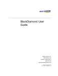
backbone. Figure 1 shows an example of a Gigabit Ethernet backbone
within a building.
Network Configuration Example
19
Switch 3300
Switch 3300
Switch 3300
Switch 3300
Switch 9100
To Backbone
Key
Fast Ethernet
Server
Gigabit Ethernet
Workstation
91_001
Figure 1 Switch 9100 used in a backbone configuration
The Switch 3300 on each floor has a 1000Mbps full-duplex link to the
Switch 9100. Two servers on one floor of the building are connected to
the Switch 9100 by way of two Gigabit Ethernet links. The two Gigabit
Ethernet fiber ports on the Switch 9100 connect into a Gigabit Ethernet
campus backbone.
Using Gigabit Ethernet as a backbone technology removes bottlenecks by
providing scalable bandwidth, low-latency, and high-speed data
switching.
20
CHAPTER 1: SWITCH 9100 OVERVIEW
In addition to providing a Gigabit backbone between Fast Ethernet
workgroups, Gigabit Ethernet equipped file servers and services may be
directly attached to the Switch 9100 providing improved performance to
the Fast Ethernet desktop.
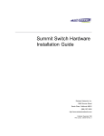
Switch 9100 Front
View
Figure 2 shows the Switch 9100 front view.
Port status LEDs
3C17705
100/1000 Mbps ports
1
2
3
4
5
Gigabit Ethernet ports
6
7
8
Unit status LEDs
91_front
Figure 2 Switch 9100 front view
The front panel has the following features:
Ports
WARNING: RJ-45 Ports. These are shielded RJ-45 data sockets. They
cannot be used as telephone sockets. Only connect RJ-45 data
connectors to these sockets.
Either shielded or unshielded data cables with shielded or unshielded
jacks can be connected to these data sockets.
AVERTISSEMENT: Les ports RJ-45. Il s'agit de prises femelles blindées
de données RJ-45. Vous ne pouvez pas les utiliser comme prise de
téléphone. Branchez uniquement des connecteurs de données RJ-45 sur
ces prises femelles.
Les câbles de données blindés ou non blindés, avec les jacks blindés ou
non blindés, l'un ou l'autre, peuvent être branchés à ces prises de courant
de données.
Switch 9100 Front View
21
WARNHINWEIS: RJ-45 Ports. RJ-45-Anschlüsse. Dies sind
abgeschirmte RJ-45-Datenbuchsen. Sie können nicht als
Telefonanschlußbuchsen verwendet werden. An diesen Buchsen dürfen
nur RJ-45-Datenstecker angeschlossen werden.
Diese Datenstecker können entweder mit abgeschirmten oder
unabgeschirmten Datenkabeln mit abgeschirmten oder unabgeschirmten
Klinkensteckern verbunden werden.
The Switch 9100 has six autosensing 100/1000BASE-TX ports using
standard RJ-45 connectors. It also has two 1000BASE-SX ports that use
standard MT-RJ connectors.
The Switch 9100 ports support the media types and distances listed in
Table 3.
Table 3 Media Types and Distances
Standard
Media Type
Mhz/Km Rating
100BASE-TX
Category 5 UTP Cable (100Mbps)
1000BASE-T
Category 5 UTP Cable (1000Mbps)
1000BASE-SX (850 nm)
62.5/125 µm Multimode fiber
62.5/125 µm Multimode fiber
50/125 µm Multimode fiber
50/125 µm Multimode fiber
Maximum Distance
100 m
100 m
160
200
400
500
220 m
275 m
500 m
550 m
For more information on 1000BASE-SX characteristics refer to IEEE Draft
P802.3z/D4.2 Tables 38-2 and 38-6.
LEDs
Table 4 describes the LED behavior on the Switch 9100.
Table 4 Switch 9100 LEDs
LED
Color
Indicates
Green
Link is present; port is enabled.
Yellow
Frames are being transmitted/received on this
port.
Green flashing
Link is present; port is disabled.
Off
Link is not present.
1000BASE-SX Port Status LEDs
Link/activity
(continued)
(continued)
22
CHAPTER 1: SWITCH 9100 OVERVIEW
Table 4 Switch 9100 LEDs (continued)
LED
Color
Indicates
Green
Link is present; port is enabled.
Yellow
Frames are being transmitted/received on this
port.
Green flashing
Link is present; port is disabled.
Off
Link is not present.
Green
1000BASE-T operation.
Off
100BASE-TX operation.
Green
Either or both LEDs green indicates the Switch
9100 is powered up.
Yellow
A yellow power LED indicates a power, overheat,
or fan failure on the corresponding PSU.
Off
Both LEDs off indicates the Switch 9100 is
powered off.
Green
The Switch 9100 is operating normally.
Green flashing
(1Hz)
Power On Self Test (POST) complete, software
download is in progress.
Green flashing
(0.5Hz)
POST is in progress.
Yellow
The Switch 9100 has failed POST.
100/1000BASE-TX Port Status LEDs
Link/activity
Speed Status
Unit Status LED
Power 1 and Power 2
MGMT
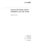
Switch 9100 Rear
View
Figure 3 shows the Switch 9100 rear view.
AC Connectors
Console port
Reset
Power 2
Power 1
91_rear
Figure 3 Switch 9100 rear view
Factory Defaults
23
The rear panel has the following features:
Power Sockets
The Switch 9100 has two, fully redundant, load-sharing power supplies.
Both automatically adjust to the supply voltage. The power supplies
operate down to 90 V. The fuse is suitable for both 110 V AC and
220–240 V AC operation.
Serial Number
The serial number uniquely identifies this unit. You will need this serial
number for fault-reporting purposes.
MAC Address
This label shows the unique Ethernet MAC address assigned to this
device.
Console Port
The console port (9-pin, “D” type connector) is used to connect a
terminal and to carry out local out-of-band management.
Reset Button
The reset button reinitializes the switch. The unit reboots with the last
saved configuration settings.
Factory Defaults
Table 5 shows the factory defaults for the Switch 9100 features.
Table 5 Switch 9100 Factory Defaults
Item
Default Setting
Console port configuration
9600 baud, eight data bits, one stop bit, no
parity, XON/XOFF flow control enabled
Serial or Telnet user account
admin with no password and user with no
password
Web network management
Enabled
Virtual LANs
One VLAN named default; all ports belong to the
default VLAN; the default VLAN belongs to the
STPD named s0
QoS
All traffic is part of a single queue (qp2)
QoS monitoring
Automatic roving
(continued)
24
CHAPTER 1: SWITCH 9100 OVERVIEW
Table 5 Switch 9100 Factory Defaults (continued)
Item
Default Setting
Spanning Tree Protocol
Disabled for the switch; enabled for each port in
the STPD
802.1p priority
Recognition enabled
802.3x flow control
Enabled on Gigabit Ethernet ports
802.1Q tagging
All packets are untagged on the default VLAN
(default)
Forwarding database aging
period
300 seconds (5 minutes)
IGMP
Enabled
IGMP snooping
Enabled
Port status
Enabled on all ports
SNMP read community string
public
SNMP write community string
private
RMON history session
Enabled
RMON alarms
Enabled
Send trap if load is greater than 75% of available
bandwidth
Send trap if there are more than 10 errors in
1,000 packets
BOOTP
Enabled on the default VLAN (default)
2
INSTALLATION AND SETUP
This chapter describes the following:
■
How to decide where to install the Switch 9100
■
Ethernet configuration rules
■
How to install the switch in a rack or free-standing
■
How to connect equipment to the console port
■
How to check the installation using the Power On Self-Test (POST)
WARNING: Safety Information. Before installing or removing any
components from the Switch 9100 or carrying out any maintenance
procedures, you must read the safety information provided in Appendix A
of this guide.
AVERTISSEMENT: Consignes de sécurité. Avant d'installer ou d'enlever
tout composant du Switch 9100 ou d'entamer une procédure de
maintenance, lisez les informations relatives à la sécurité qui se trouvent
dans l'Appendice A de ce guide.
WARNHINWEIS: Sicherheitsinformationen. Bevor Sie Komponenten
aus dem Switch 9100 entfernen oder dem Switch 9100 hinzufuegen
oder Instandhaltungsarbeiten verrichten, lesen Sie die
Sicherheitsanweisungen, die in Appendix A (Anhang A) in diesem
Handbuch aufgefuehrt sind.
Determining the
Switch 9100
Location
The Switch 9100 is suited for use in the office, where it can be
free-standing or mounted in a standard 19-inch equipment rack.
Alternatively, the device can be rack-mounted in a wiring closet or
equipment room. Two mounting brackets are supplied with the switch.
26
CHAPTER 2: INSTALLATION AND SETUP
CAUTION: When using a rack mounting system, the switch must be
mounted on a shelf or runners. The rack mounting brackets alone are not
sufficient to support the weight of the switch. The rack mounting
brackets are provided to ensure stability across the horizontal plane. If
you stack switches, you must ensure that the shelf or runners are strong
enough to hold the combined weight. Ensure that the ventilation holes
are not obstructed.
After deciding where to install the switch, make sure that:
Configuration Rules
for Ethernet
Installing the
Switch 9100
Rack Mounting
■
The switch is accessible and cables can be connected easily.
■
Water or moisture cannot enter the case of the unit.
■
Temperature must be within the range of 0 to 40 °C (32 to 104°F).
■
Air-flow around the unit and through the vents on the side of the case
is not restricted. You should provide a minimum of 75mm (3 in.)
clearance.
■
No objects are placed on top of the unit.
■
Units are not stacked more than four high if the switch is
free-standing.
The connectors, supported media types, and maximum distances for the
Switch 9100 are described in Chapter 1.
The Switch 9100 can be mounted in a rack, or placed free-standing on a
tabletop.
The Switch 9100 is 2U high and will fit in most standard 19-inch racks.
CAUTION: The switch should only be used in a rack if it is mounted on
runners, a shelf, or a tray to support the weight. The rack mount kits
alone are not sufficient to support the weight of the switch. The rack
mount kits must not be used to suspend the switch from under a table or
desk, or attach it to a wall.
CAUTION: Disconnect all cables from the switch before continuing.
Remove all self-adhesive pads from the underside of the switch, if they
have been fitted.
Installing the Switch 9100
27
To install the mounting brackets on the switch, follow these steps:
1 Place the switch the right way up on a hard flat surface, with the front
facing toward you.
2 Remove the existing screws from the sides of the chassis.
3 Locate a mounting bracket over the mounting holes on one side of the
unit.
4 Insert the four screws and fully tighten with a suitable screwdriver, as
shown in Figure 4.
Figure 4 Fitting the mounting bracket
5 Repeat the three previous steps for the other side of the switch.
6 Refer to the instructions that shipped with your rack, runners, shelf or
tray to complete the installation of the switch into the mounting rack.
CAUTION: When using rack mounting runners, a shelf, or a tray, make
sure that the ventilation holes on the side of the switch are not
obstructed.
7 Connect cables.
Free-Standing
The Switch 9100 is supplied with four self-adhesive rubber pads. Apply
the pads to the underside of the device by sticking a pad in the marked
area at each corner of the switch.
28
CHAPTER 2: INSTALLATION AND SETUP
Stacking the Switch
and Other Devices
Up to four units can be placed on top of one another. If mixing
SuperStack II devices, the smaller units must be positioned at the top
using rubber pads.
This section relates only to physically placing the devices on top of each
other. The switch cannot be used to form a logical stack. It cannot be
linked to other switches using special expansion cables to form a larger
switch.
Apply the pads to the underside of the device by sticking a pad in the
marked area at each corner of the switch. Place the devices on top of
each other, ensuring that the pads of the upper device line up with the
recesses of the lower device.
Connecting
Equipment to the
Console Port
Connection to the console port is used for direct local management. The
Switch 9100 console port settings are set as follows:
■
Baud rate — 9600
■
Data bits — 8
■
Stop bit — 1
■
Parity — None
■
Flow control — XON/XOFF
The terminal connected to the console port on the switch must be
configured with the same settings. This procedure will be described in the
documentation supplied with the terminal.
Appropriate cables are available from your local supplier. To make your
own cables, pinouts for a DB-9 male console connector are described in
Table 6.
Table 6 Console Connector Pinouts
Function
Pin Number
Direction
DCD (data carrier detect)
1
In
RXD (receive data)
2
In
TXD (transmit data)
3
Out
DTR (data terminal ready)
4
Out
(continued)
(continued)
Connecting Equipment to the Console Port
29
Table 6 Console Connector Pinouts (continued)
Function
Pin Number
Direction
GND (ground)
5
-
DSR (data set ready)
6
In
RTS (request to send)
7
Out
CTS (clear to send
8
In
Figure 5 shows the pin-outs for a 9-pin to RS-232 25-pin null modem
cable.
Switch 9100
PC/Terminal
Cable connector: 9-pin female
Cable connector: 25-pin male/female
Screen Shell
3
TxD
2
RxD
Ground 5
7
RTS
8
CTS
6
DSR
1
DCD
4
DTR
Figure 5 Null modem cable pin-outs
1
3
2
7
4
20
5
6
8
Screen
RxD
TxD
Ground
RTS
DTR
CTS
DSR
DCD
91_ser1
30
CHAPTER 2: INSTALLATION AND SETUP
Figure 6 shows the pin-outs for a 9-pin to 9-pin PC-AT serial null modem
cable.
Switch 9100
PC-AT Serial Port
Cable connector: 9-pin female
Cable connector: 9-pin female
Screen Shell
4
DTR
3
TxD
2
RxD
8
CTS
Ground 5
6
DSR
7
RTS
1
DCD
Shell Screen
1
DCD
2
RxD
3
TxD
4
DTR
5 Ground
6
DSR
7
RTS
8
CTS
91_ser2
Figure 6 PC-AT serial cable pin-outs
Powering-up the
Switch
The Switch 9100 contains two power supplies. When both are
connected, the power supplies operate in a load-sharing configuration. If
one power supply fails, the other power supply takes over, ensuring
uninterrupted network operation. Either one, or both power supplies may
be connected to power the switch. It is recommended that you connect
both power supplies.
To power-up the switch, follow these steps:
1 Connect one or both power cables to the switch.
2 Connect the power cable(s) to the wall outlet(s).
The switch automatically powers-up once it has been connected to the
wall outlet.
Checking the
Installation
Power On Self-Test
(POST)
After turning on power to the Switch 9100, the device performs a Power
On Self-Test (POST).
During the POST, all ports are temporarily disabled, the packet LED is off,
the power LED is on, and the MGMT LED flashes green. The MGMT LED
flashes until the switch has successfully passed the POST.
Logging on for the First Time
31
If the switch passes the POST, the MGMT LED stops blinking and remains
green. If the switch fails the POST, the MGMT LED shows a solid yellow
light.
Logging on for the
First Time
After the switch has completed the POST, it is operational. Once
operational, you can log on to the switch and configure an IP address for
the default VLAN (named default).
To manually configure the IP settings, perform the following steps:
1 Connect a terminal or workstation running terminal emulation software
to the console port.
2 At your terminal, press [Return] until you see the logon prompt.
3 At the logon prompt, enter the default user name admin to log on with
administrator privileges. For example:
login: admin
Administrator capabilities allow you to access all switch functions. For
more information on switch security, refer to Chapter 3.
4 At the password prompt, press [Return].
The default name, admin, has no password assigned. When you have
successfully logged on to the switch, the command-line prompt displays
the name of the switch in its prompt.
5 Assign an IP address and subnetwork mask for VLAN default. The
example below assigns an IP address of 123.45.67.8 and a subnetwork
mask of 255.255.255.0.
config vlan default ipaddress 123.45.67.8 255.255.255.0
Your changes take effect immediately.
6 Save your configuration changes so that they will be in effect after the
next switch reboot, by typing
save
For more information on saving configuration changes, refer to
Chapter 10.
7 When you are finished using the facility, log out of the switch by typing
logout
32
CHAPTER 2: INSTALLATION AND SETUP
3
ACCESSING THE SWITCH
This chapter provides the following required information to begin
managing the Switch 9100:
■
Understanding the command syntax
■
Line-editing commands
■
Command history substitution
■
Configuring the switch for management
■
Switch management methods
■
Configuring SNMP
■
Checking basic connectivity
■
Enabling and disabling individual ports
■
Configuring the port speed (100/1000BASE-TX ports only)
■
Configuring half- or full-duplex mode
■
Creating load-sharing groups on multiple ports
For configuration changes to be retained through a power cycle or
reboot, you must issue a SAVE command after you have made the
change. For more information on the SAVE command, refer to
Chapter 10.
34
CHAPTER 3: ACCESSING THE SWITCH
Understanding the
Command Syntax
This section describes the steps to take when entering a command. Refer
to the sections that follow for detailed information on using the
command-line interface.
To use the command-line interface (CLI), follow these steps:
1 When entering a command at the prompt, ensure that you have the
appropriate privilege level.
Most configuration commands require you to have the administrator
privilege level.
2 Enter the command name.
If the command does not include a parameter or values, skip to Step 3. If
the command requires more information, continue to Step 2a.
a If the command includes a parameter, enter the parameter name and
values.
b The value part of the command specifies how you want the parameter
to be set. Values include numerics, strings, or addresses, depending on
the parameter.
3 After entering the complete command, press [Return].
If an asterisk (*) appears in front of the command-line prompt, it
indicates that you have outstanding configuration changes that have not
been saved. For more information on saving configuration changes, refer
to Chapter 10.
Syntax Helper
The CLI has a built-in syntax helper. If you are unsure of the complete
syntax for a particular command, enter as much of the command as
possible and press [Return]. The syntax helper provides a list of options
for the remainder of the command.
The syntax helper also provides assistance if you have entered an incorrect
command.
Command
Completion with
Syntax Helper
The switch provides command completion by way of the [Tab] key. If you
enter a partial command, pressing the [Tab] key posts a list of available
options, and places the cursor at the end of the command.
Understanding the Command Syntax
Abbreviated Syntax
35
Abbreviated syntax is the shortest, most unambiguous, allowable
abbreviation of a command or parameter. Typically, this is the first three
letters of the command.
When using abbreviated syntax, you must enter enough characters to
make the command unambiguous, and distinguishable to the switch.
Command Shortcuts
All named components of the switch configuration must have a unique
name. Components are named using the create command. When you
enter a command to configure a named component, you do not need to
use the keyword of the component. For example, to create a VLAN, you
must enter a unique VLAN name:
create vlan engineering
Once you have created the VLAN with a unique name, you can then
eliminate the keyword vlan from all other commands that require the
name to be entered. For example, instead of entering the Switch 9100
command
config vlan engineering delete port 1-3,6
you could enter the following shortcut:
config engineering delete port 1-3,6
Switch 9100
Numerical Ranges
Commands that require you to enter one or more port numbers on a
Switch 9100 use the parameter <portlist> in the syntax. A portlist can
be a range of numbers, for example:
ports 1-3
You can add additional port numbers to the list, separated by a comma:
ports 1-3,6,8
Names
All named components of the switch configuration must have a unique
name. Names must begin with an alphabetical character and are
delimited by whitespace, unless enclosed in quotation marks.
36
CHAPTER 3: ACCESSING THE SWITCH
Symbols
You may see a variety of symbols shown as part of the command syntax.
These symbols explain how to enter the command, and you do not type
them as part of the command itself. Table 7 summarizes command syntax
symbols.
Table 7 Command Syntax Symbols
Symbol
Description
angle brackets < >
Enclose a variable or value. You must specify the variable or value. For
example, in the syntax
config vlan <name> ipaddress <ip_address>
you must supply a VLAN name for <name> and an address for
<ip_address> when entering the command. Do not type the angle
brackets.
square brackets [ ]
Enclose a required value or list of required arguments. One or more values or
arguments can be specified. For example, in the syntax
use image [primary | secondary]
you must specify either the primary or secondary image when entering the
command. Do not type the square brackets.
vertical bar |
Separates mutually exclusive items in a list, one of which must be entered. For
example, in the syntax
config snmp community [readonly | readwrite] <string>
you must specify either the read or write community string in the command.
Do not type the vertical bar.
braces { }
Enclose an optional value or a list of optional arguments. One or more values
or arguments can be specified. For example, in the syntax
reboot {<date> <time> | cancel}
you can specify either a particular date and time combination, or the keyword
cancel to cancel a previously scheduled reboot. If you do not specify an
argument, the command will prompt, asking if you want to reboot the switch
now. Do not type the braces.
Line-Editing Keys
Line-Editing Keys
37
Table 8 describes the line-editing keys available using the CLI.
Table 8 Line-Editing Keys
Key(s)
Description
Backspace
Deletes character to the left of cursor and shifts the remainder of line to left.
Delete or [Ctrl] + D
Deletes character under cursor and shifts the remainder of line to left.
[Ctrl] + K
Deletes characters from under cursor to the end of the line.
Insert
Toggles on and off. When toggled on, inserts text and shifts previous
text to right.
Left Arrow
Moves cursor to left.
Right Arrow
Moves cursor to right.
[Ctrl] + L
Clears the screen and moves the cursor to the beginning of the line.
[Ctrl] + U
Clears all characters typed from the cursor to the beginning of the line.
[Ctrl] + W
Deletes the previous word.
Up Arrow
Displays the previous command in the command history buffer and places
cursor at end of command.
Down Arrow
Displays the next command in the command history buffer and places cursor
at end of command.
Command History
The switch “remembers” the last 49 commands you have entered. You
can display a list of these commands by using the following command:
history
Common
Commands
Table 9 describes common commands used to manage the switch.
Commands specific to a particular feature are described in the other
chapters of this guide.
Table 9 Common Commands
Command
Description
create account [admin | user]
<username> {encrypted} {<password>}
Creates a user account. The encrypted
option should only be used by the switch to
generate an ASCII configuration (using the
upload configuration command), and
parsing a switch-generated configuration
(using the download configuration
command).
(continued)
38
CHAPTER 3: ACCESSING THE SWITCH
Table 9 Common Commands (continued)
Command
Description
create vlan <name>
Creates a VLAN.
config account <username> {encrypted}
{<password>}
Configures a user account password.
Passwords must have a minimum of four
characters and can have a maximum of 12
characters. User names and passwords are
case-sensitive.
config banner
Configures the banner string. You can enter
up to 24 rows of 80-column text that is
displayed before the login prompt of each
session. Press [Return] at the beginning of a
line to terminate the command and apply the
banner. To clear the banner, press [Return] at
the beginning of the first line.
config time <date> <time>
Configures the system date and time. The
format is as follows:
mm/dd/yyyy hh:mm:ss
The time uses a 24-hour clock format. You
cannot set the year past 2023.
config timezone <gmt_offset> {autodst |
noautodst}
Configures the time zone information to the
configured offset from GMT time. The format
of gmt_offset is +/- minutes from GMT
time. Specify:
■
■
autodst — Enables automatic Daylight
Savings Time change.
nosautodst — Disables automatic
Daylight Savings Time change.
The default setting is autodst.
config vlan <name> ipaddress
<ip_address> {<mask>}
Configures an IP address and subnet mask
for a VLAN.
disable autodst
Disables automatic Daylight Savings Time
change.
enable autodst
Enables automatic Daylight Savings Time
change.
enable bootp vlan [<name> | all]
Enables BOOTP for one or more VLANs.
enable cli-config-logging
Enables logging CLI configuration commands
to the syslog for auditing purposes.
enable clipaging
Enables pausing at the end of each CLI
screen, allowing you to use a scripting
language to get switch status.
(continued)
Common Commands
Table 9 Common Commands (continued)
Command
Description
enable idletimeout
Enables a timer that disconnects all sessions
(both Telnet and console) after 20 minutes of
inactivity. The default setting is disabled.
enable telnet {access-profile
<access_profile> | none} {port
<tcp_port_number>}
Enables Telnet access to the switch. By
default, Telnet is enabled with no access
profile, and uses TCP port 23. The none
option removes any previously configured
access profile assignment.
enable web {access-profile
<access_profile> | none} {port
<tcp_port_number>}
Enables web access to the switch. By default,
web access is enabled with no access profile,
using TCP port number 80. You must reboot
the switch before this command takes effect.
The none option removes any previously
configured access profile assignment.
history
Displays the previous 49 commands entered
on the switch.
clear session <number>
Terminates a Telnet session from the switch.
disable bootp vlan [<name> | all]
Disables BOOTP for one or more VLANs.
disable cli-config-logging
Disables logging CLI configuration
commands to the syslog for auditing
purposes.
disable clipaging
Disables pausing at the end of each CLI
screen.
disable idletimeout
Disables the timer that disconnects all
sessions. Once disabled, console sessions
remain open until the switch is rebooted or
you logoff. Telnet sessions remain open until
you close the Telnet client.
disable telnet
Disables Telnet access to the switch.
disable web
Disables Web access to the switch.
delete account <username>
Deletes a user account.
delete vlan <name>
Deletes a VLAN.
(continued)
39
40
CHAPTER 3: ACCESSING THE SWITCH
Table 9 Common Commands (continued)
Command
Description
unconfig switch {all}
Resets all switch parameters (with the
exception of defined user accounts, and date
and time information) to the factory defaults.
If you specify the keyword all, the user
account information is reset as well.
show banner
Displays the user-configured banner.
Configuring
Management
Access
The Switch 9100 supports the following two level levels of management:
■
User
■
Administrator
A user-level account has viewing access to all manageable parameters,
with the exception of the following:
■
User account database
■
SNMP community strings
A user-level account can use the ping command to test device
reachability, and change the password assigned to the account name. If
you have logged on with user capabilities, the command-line prompt
ends with a (>) sign. For example:
3C17705:2>
An administrator-level account can view and change all switch
parameters. It can also add and delete users, and change the password
associated with any account name. The administrator can disconnect a
management session that has been established by way of a Telnet
connection. If this happens, the user logged on by way of the Telnet
connection is notified that the session has been terminated.
If you have logged on with administrator capabilities, the command-line
prompt ends with a (#) sign. For example:
3C17705:18#
The prompt text is taken from the SNMP sysname setting. The number
that follows the colon indicates the sequential line/command number.
Configuring Management Access
41
If an asterisk (*) appears in front of the command-line prompt, it indicates
that you have outstanding configuration changes that have not been
saved. For example:
*3C17705:19#
For more information on saving configuration changes, refer to
Chapter 10.
Default Accounts
By default, the switch is configured with two accounts, as shown in
Table 10.
Table 10 Default Accounts
Account Name
Access Level
admin
This user can access and change all manageable
parameters. The admin account cannot be deleted.
user
This user can view (but not change) all manageable
parameters, with the following exceptions:
■
This user cannot view the user account database.
■
This user cannot view the SNMP community strings.
Changing the Default Password
Default accounts do not have passwords assigned to them. Passwords
must have a minimum of four characters and can have a maximum of 12
characters.
User names and passwords are case-sensitive.
To add a password to the default admin account, follow these steps:
1 Log in to the switch using the name admin.
2 At the password prompt, press [Return].
3 Add a default admin password by typing the following:
config account admin
4 Enter the new password at the prompt.
5 Re-enter the new password at the prompt.
42
CHAPTER 3: ACCESSING THE SWITCH
To add a password to the default user account, follow these steps:
1 Log in to the switch using the name admin.
2 At the password prompt, press [Return], or enter the password that you
have configured for the admin account.
3 Add a default user password by typing the following:
config account user
4 Enter the new password at the prompt.
5 Re-enter the new password at the prompt.
If you forget your password while logged out of the command-line
interface, contact your supplier, who will advise on your next course of
action.
Creating a
Management
Account
The switch can have a total of 16 management accounts. You can use the
default names (admin and user), or you can create new names and
passwords for the accounts. Passwords must have a minimum of four
characters and can have a maximum of 12 characters.
To create a new account, follow these steps:
1 Log in to the switch as admin.
2 At the password prompt, press [Return], or enter the password that you
have configured for the admin account.
3 Add a new user by using the following command:
create account [admin | user] <username> {encrypted}
4 Enter the password at the prompt.
5 Re-enter the password at the prompt.
Viewing Accounts
To view the accounts that have been created, you must have
administrator privileges. Use the following command to see the accounts:
show accounts
Methods of Managing the Switch 9100
43
Deleting an Account
To delete an account, you must have administrator privileges. Use the
following command to delete an account:
delete account <username>
The account name admin cannot be deleted.
Methods of
Managing the
Switch 9100
You can manage the switch using the following methods:
■
Access the CLI by connecting a terminal (or workstation with
terminal-emulation software) to the console port.
■
Access the CLI over a TCP/IP network using a Telnet connection.
■
Access the Web interface over a TCP/IP network, using a standard
Web browser (such as Netscape Navigator 3.0 or greater, or Microsoft
Internet Explorer 3.0 or greater).
■
Use an SNMP Network Manager over a network running the IP
protocol.
The switch can support multiple user sessions concurrently, as follows:
Using the Console
Interface
■
One console session
■
Eight Telnet sessions
■
One Web session
The CLI built into the switch is accessible by way of the 9-pin, RS-232 port
labelled console, located on the back of the Switch 9100.
For more information on the console port pinouts, refer to Chapter 2.
Once the connection is established, you will see the switch prompt and
you may log in.
Using Access
Profiles
Access profiles are used by several switch features as a way to restrict
access. An access profile is a named list of IP addresses and subnet masks.
To use access profiles, you must first define the list, and then apply the
named list to the desired application.
44
CHAPTER 3: ACCESSING THE SWITCH
The most common applications that use access profiles allow you to
remotely manage the switch across the network, for example:
Creating an Access
Profile
■
SNMP read access
■
SNMP read and write access
■
Telnet
■
Web access
Access profiles are created to specifically permit or deny users access to
an application. Access is restricted by assigning an access profile to the
service that is being used for remote access. First, create and configure
the access profile with the desired controls. Next, configure the
application to use the access profile that you have created. You must
configure the application to use the named access profile. Otherwise, no
restrictions are applied. Table 11 lists access profile commands.
Table 11 Access Profile Configuration Commands
Command
Description
config access-profile <access_profile>
add ipaddress <ipaddress>
<subnet_mask>}
Adds an IP address to the access profile.
config access-profile <access_profile>
delete ipaddress <ipaddress>
<subnet_mask>
Deletes an IP address from the access profile.
config access-profile <access_profile>
mode [permit | deny]
Configures the access profile to be one of the
following:
■
■
permit — Allows the addresses that
match the access profile description.
deny — Denies the addresses that match
the access profile description.
The default setting is permit.
create access-profile <access_profile>
type ipaddress
Creates an access profile. Once the access
profile is created, one or more addresses can
be added to it, and the profile can be used to
control access to an application.
delete access-profile <access_profile>
Deletes an access profile.
show access-profile <access_profile>
Displays access-profile related information for
the switch.
Using Access Profiles
45
The subnet mask specified in the access profile command is interpreted as
a reverse mask. A reverse mask indicates the bits that are significant in
the IP address. In other words, a reverse mask specifies the part of the
address that must match the IP address to which the profile is applied.
If you configure an IP address that is an exact match that is specifically
denied or permitted, use a mask of /32 (for example, 141.251.24.28/32).
If the IP address represents a subnet address that you wish to deny or
permit, then configure the mask to cover only the subnet portion (for
example, 141.251.10.0/24).
If you are using off-byte boundary subnet masking, the same logic
applies, but the configuration is more tricky. For example, the address
141.251.24.128/27 represents any host from subnet 141.251.24.128.
Access Profile Rules
The following rules apply when using access profiles:
■
Only one access profile can be applied to each application.
■
The access profile can either permit or deny the entries in the profile.
■
The same access profile can be applied to more than one application.
There is an implicit aspect to access profiles. For instance, if an access
profile of mode permit is applied, then all other sources are assumed
denied, and are not permitted access to the application. On the other, if
an access profile of mode deny is applied, then all other sources are
assumed permitted.
Access Profile Example
The following example creates an access profile named testpro, and
denies access for the device with the IP address 192.168.10.10:
create access-profile testpro type ipaddress
config access-profile testpro mode deny
config access-profile testpro add ipaddress 192.168.10.10/32
The following command applies the access profile testpro to Telnet:
enable telnet access-profile testpro
To view the contents of an access profile, type:
show access-profile <access_profile>
46
CHAPTER 3: ACCESSING THE SWITCH
To view the Telnet configuration, type:
show management
Using Telnet
Any workstation with a Telnet facility should be able to communicate
with the switch over a TCP/IP network.
Up to eight active Telnet sessions can access the switch concurrently. If
idle timeouts are enabled, the Telnet connection will time out after
20 minutes of inactivity. If a connection to a Telnet session is lost
inadvertently, the switch terminates the session within two hours.
Before you can start a Telnet session, you must set up the IP parameters
described in the section “Configuring Switch IP Parameters,” later in this
chapter. Telnet is enabled by default.
To open the Telnet session, you must specify the IP address of the device
that you want to manage. Check the user manual supplied with the
Telnet facility if you are unsure of how to do this.
Once the connection is established, you will see the switch prompt and
you may log in.
Connecting to
Another Host Using
Telnet
You can Telnet from the current CLI session to another host using the
following command:
telnet <ipaddress> {<port_number>}
If the TCP port number is not specified, the Telnet session defaults to
port 23. Only VT100 emulation is supported.
Configuring Switch IP
Parameters
To manage the switch by way of a Telnet connection or by using an SNMP
Network Manager, you must first configure the switch IP parameters.
Using a BOOTP Server
If you are using IP and you have a Bootstrap Protocol (BOOTP) server set
up correctly on your network, you must add the following information to
the BOOTP server:
■
Switch Media Access Control (MAC) address
■
IP address
Using Telnet
■
47
Subnet address mask (optional)
The switch MAC address is found on the rear label of the switch.
Once this is done, the IP address and subnetwork mask for the switch will
be downloaded automatically. You can then start managing the switch
without further configuration.
You can enable BOOTP on a per-VLAN basis by using the following
command:
enable bootp vlan [<name> | all]
By default, BOOTP is enabled on the default VLAN.
If you configure the switch to use BOOTP, the switch IP address is not
retained through a power cycle, even if the configuration has been saved.
To retain the IP address through a power cycle, you must configure the IP
address of the VLAN using the command-line interface, Telnet, or Web
interface.
All VLANs within a switch that are configured to use BOOTP to get their IP
address use the same MAC address. Therefore, if you are using BOOTP
relay through a router, the BOOTP server must be capable of
differentiating its relay based on the gateway portion of the BOOTP
packet.
Manually Configuring the IP Settings
If you are using IP without a BOOTP server, you must enter the IP
parameters for the switch in order for the SNMP Network Manager,
Telnet software, or Web interface to communicate with the device. To
assign IP parameters to the switch, you must do the following:
■
Log in to the switch with administrator privileges.
■
Assign an IP address and subnetwork mask to a VLAN.
The switch comes configured with a default VLAN named default. To
use Telnet or an SNMP Network Manager, you must have at least one
VLAN on the switch, and it must be assigned an IP address and
subnetwork mask. IP addresses are always assigned to a VLAN. The
switch can be assigned multiple IP addresses.
For information on creating and configuring VLANs, refer to Chapter 4.
48
CHAPTER 3: ACCESSING THE SWITCH
To manually configure the IP settings, perform the following steps:
1 Connect a terminal or workstation running terminal-emulation software
to the console port.
2 At your terminal, press [Return] one or more times until you see the login
prompt.
3 At the login prompt, enter your user name and password. Note that they
are both case-sensitive. Ensure that you have entered a user name and
password with administrator privileges.
■
If you are logging in for the first time, use the default user name
admin to log in with administrator privileges. For example:
login: admin
Administrator capabilities enable you to access all switch functions.
The default user names have no passwords assigned.
■
If you have been assigned a user name and password with
administrator privileges, enter them at the login prompt.
4 At the password prompt, enter the password and press [Return].
When you have successfully logged in to the switch, the command-line
prompt displays the name of the switch in its prompt.
5 Assign an IP address and subnetwork mask for the default VLAN by using
the following command:
config vlan <name> ipaddress <ipaddress> {<subnet_mask>}
For example:
config vlan default ipaddress 123.45.67.8 255.255.255.0
Your changes take effect immediately.
As a general rule, when configuring any IP addresses for the switch, you
can express a subnet mask by using dotted decimal notation, or by using
classless inter-domain routing notation (CIDR). CIDR uses a forward slash
plus the number of bits in the subnet mask. Using CIDR notation, the
command identical to the one above would be:
config vlan default ipaddress 123.45.67.8 / 24
6 Configure the default route for the switch using the following command:
config iproute add default <ipaddress> {<metric>}
Using Telnet
49
For example:
config iproute add default 123.45.67.1
7 Save your configuration changes so that they will be in effect after the
next switch reboot, by typing
save
For more information on saving configuration changes, refer to
Chapter 10.
8 When you are finished using the facility, log out of the switch by typing
logout or quit
Disconnecting a
Telnet Session
An administrator-level account can disconnect a management session
that has been established by way of a Telnet connection. If this happens,
the user logged in by way of the Telnet connection is notified that the
session has been terminated.
To terminate a Telnet session, follow these steps:
1 Log in to the switch with administrator privileges.
2 Determine the session number of the session you want to terminate by
using the following command:
show session
3 Terminate the session by using the following command:
clear session <session_number>
Disabling Telnet
Access
By default, Telnet services are enabled on the switch. You can choose to
disable Telnet by entering:
disable telnet
To re-enable Telnet on the switch, at the console port enter
enable telnet {access-profile <access_profile> | none} {port
<port_number>}
You must be logged in as an administrator to enable or disable Telnet.
50
CHAPTER 3: ACCESSING THE SWITCH
IP Host
Configuration
Commands
Table 12 describes the commands that are used to configure IP settings
on the switch.
Table 12 IP Host Configuration Commands
Command
Description
config iparp add <ipaddress>
<mac_address>
Adds a permanent entry to the Address
Resolution Protocol (ARP) table. Specify the IP
address and MAC address of the entry.
config iparp delete <ipaddress>
Deletes an entry from the ARP table. Specify
the IP address of the entry.
config iparp timeout <minutes>
Configures the IP ARP timeout period. The
default setting is 20 minutes. A setting of 0
disables ARP aging.
clear iparp {<ipaddress> | vlan <name>} Removes dynamic entries in the IP ARP table.
Permanent IP ARP entries are not affected.
config iproute add default <gateway>
{<metric>}
Adds a default gateway to the routing table.
A default gateway must be located on a
configured IP interface. If no metric is
specified, the default metric of one is used.
config iproute delete default <gateway> Deletes a default gateway from the routing
table.
show iparp {<ipaddress> | vlan <name> |
permanent}
Displays the IP ARP table. You can filter the
display by IP address, VLAN, or permanent
entries.
show iproute {vlan <name> | <ipaddress>
<mask>}
Displays the contents of the IP routing table.
Using the Web
Interface
The Web Interface is device-management software running in the switch
that enables you to access the switch over a TCP/IP network using a
standard Web browser. Any properly configured standard Web browser
that supports frames (such as Netscape Navigator 3.0 or Microsoft
Internet Explorer 3.0) can manage the switch over a TCP/IP network.
For more information on assigning an IP address, refer to the section,
“Configuring Switch IP Parameters,” on page 46.
Using SNMP
51
The default home page of the switch can be accessed using the following
command:
http://<ipaddress>
When you access the home page of the switch, you are presented with
the Logon screen.
For more information on using the Web Interface, refer to Chapter 9.
Disabling Web Access
By default, Web access is enabled on the switch. To disable it, enter the
following command:
disable web
To re-enable Web access, enter the following command:
enable web {access-profile <access_profile> | none} {port
<tcp_port_number>}
Reboot the switch for these changes to take effect.
For more information on rebooting the switch, refer to Chapter 10.
Using SNMP
Any Network Manager running the Simple Network Management
Protocol (SNMP) can manage the switch, provided the Management
Information Base (MIB) is installed correctly on the management station.
Each Network Manager provides its own user interface to the
management facilities.
The following sections describe how to get started if you want to use an
SNMP manager. It assumes you are already familiar with SNMP
management.
Accessing Switch
Agents
To have access to the SNMP agent residing in the switch, at least one
VLAN must have an IP address assigned to it.
For more information on assigning IP addresses, refer to Table 9.
Supported MIBs
Any Network Manager running SNMP can manage the switch, provided
the MIB is installed correctly on the management station. In addition to
private MIBs, the switch supports the standard MIBs listed in Appendix B.
52
CHAPTER 3: ACCESSING THE SWITCH
Configuring SNMP
Settings
The following SNMP parameters can be configured on the switch:
■
Authorized trap receivers — An authorized trap receiver can be one
or more network management stations on your network. The switch
sends SNMP traps to all trap receivers. You can have a maximum of six
trap receivers configured for each switch. Entries in this list can be
created, modified, and deleted using the RMON2 trapDestTable MIB
variable, as described in RFC 2021.
■
Authorized managers — An authorized manager can be either a
single network management station, or a range of addresses (for
example, a complete subnet) specified by a prefix and a mask. The
switch can have a maximum of eight authorized managers.
■
Community strings — The community strings allow a simple method
of authentication between the switch and the remote Network
Manager. There are two types of community strings on the switch.
Read community strings provide read-only access to the switch. The
default read-only community string is public. Read-write community
strings provide read and write access to the switch. The default
read-write community string is private. A total of eight community
strings can be configured on the switch. The community string for all
authorized trap receivers must be configured on the switch for the
trap receiver to receive switch-generated traps. SNMP community
strings can contain up to 126 characters.
■
System contact (optional) — The system contact is a text field that
enables you to enter the name of the person(s) responsible for
managing the switch.
■
System name — The system name is the name that you have
assigned to this switch. The default name is the model name of the
switch (for example, 3C17705).
■
System location (optional) — Using the system location field, you
can enter an optional location for this switch.
Table 13 describes SNMP configuration commands.
Table 13 SNMP Configuration Commands
Command
Description
enable snmp access
Turns on SNMP support for the switch.
enable snmp traps
Turns on SNMP trap support.
(continued)
Using SNMP
Table 13 SNMP Configuration Commands (continued)
Command
Description
config snmp access-profile [readonly |
readwrite] {<access_profile> | none}
Applies an access profile for SNMP access.
You can create different access profiles for
readonly and readwrite access to the switch.
The none option removes any previously
configured access profile assignment.
config snmp add trapreceiver
<ipaddress> community <string>
Adds the IP address of a specified trap
receiver. The IP address can be a unicast,
multicast, or broadcast. A maximum of six
trap receivers is allowed.
config snmp community [readonly |
readwrite] <string>
Adds an SNMP read or read/write community
string. The default readonly community
string is public. The default readwrite
community string is private. Each
community string can have a maximum of
126 characters, and can be enclosed by
double quotation marks.
Deletes the IP address of a specified trap
config snmp delete trapreceiver
[<ip_address> community <string> | all] receiver or all authorized trap receivers.
config snmp syscontact <string>
Configures the name of the system contact.
A maximum of 255 characters is allowed.
config snmp sysname <string>
Configures the name of the switch. A
maximum of 32 characters is allowed. The
default sysname is the model name of the
device (for example, 3C17705). The
sysname appears in the switch prompt.
config snmp syslocation <string>
Configures the location of the switch. A
maximum of 255 characters is allowed.
Displaying SNMP
Settings
To display the SNMP settings configured on the switch, enter the
following command:
show management
This command displays the following information:
■
Enable/disable state for Telnet, SNMP, and Web access
■
SNMP community strings
■
Authorized SNMP station list
■
SNMP trap receiver list
■
RMON polling configuration
53
54
CHAPTER 3: ACCESSING THE SWITCH
Resetting and
Disabling SNMP
■
Login statistics
■
Access profile assignments
To reset and disable SNMP settings, use the commands in Table 14.
Table 14 SNMP Reset and Disable Commands
Command
Description
disable snmp access
Disables SNMP on the switch. Disabling SNMP access does
not affect the SNMP configuration (for example,
community strings).
disable snmp traps
Prevents SNMP traps from being sent from the switch. Does
not clear the SNMP trap receivers that have been
configured.
unconfig management
Restores default values to all SNMP-related entries.
Checking Basic
Connectivity
The switch offers the ping command for checking basic connectivity. The
ping command enables you to send Internet Control Message Protocol
(ICMP) echo messages to a remote IP device. The ping command is
available for both the user and administrator privilege level.
The ping command syntax is
ping {continuous} {size <n>} <ip_address>
Options for the ping command are described in Table 15.
Table 15 Ping Command Parameters
Parameter
Description
continuous
Specifies ICMP echo messages to be sent continuously. This
option can be interrupted by pressing any key.
size <n>
Specifies the size of the packet.
<ipaddress>
Specifies the IP address of the host.
If a ping request fails, the switch continues to send ping messages until
interrupted. Press any key to interrupt a ping request.
Enabling and Disabling Switch 9100 Ports
Enabling and
Disabling
Switch 9100 Ports
55
By default, all ports are enabled. To enable or disable one or more ports,
use the following command:
[enable | disable] ports <portlist>
For example, to disable ports 1, 3, and 5 through 7 on the Switch 9100,
enter the following:
disable ports 1,3,5-7
Even though a port is disabled, the link remains enabled for diagnostic
purposes.
Configuring Switch
9100 Port Speed
and Duplex Setting
100/1000BASE-T Ports
By default, the Switch 9100 is configured to use autonegotiation to
determine the port speed and duplex setting for each 100/1000BASE-TX
port. The 100/1000 Mbps ports can connect to either 100BASE-TX or
1000BASE-T networks. At 1000 Mbps, all ports operate at full-duplex,
only.
Autonegotiation is mandatory for a 1000BASE-TX connection, so cannot
be disabled if a 1000BASE-TX connection is required. If you do not want
your 100/1000BASE-TX ports to autonegotiate you can select to manually
configure the speed to 100 Mbps, and the duplex setting to full or
half-duplex operation.
To disable autonegotiation and configure port speed and duplex setting
for a fixed 100BASE-T connection, use the following command:
config ports <portlist> auto off speed 100 duplex [half |
full]
1000BASE-SX Ports
1000BASE-SX ports are statically set to 1 Gbps and full-duplex, neither of
which can be modified. By default, the ports autonegotiate. However,
you can manually disable autonegotiation, using the following command:
config ports <portlist> auto off duplex full
Enabling
Autonegotiation
To configure the switch to autonegotiate, use the following command:
config ports <portlist> auto on
56
CHAPTER 3: ACCESSING THE SWITCH
Flow Control
Switch 9100 Port
Commands
Flow control is supported on Gigabit Ethernet ports. It is enabled or
disabled as part of autonegotiation. If autonegotiation is set to off, flow
control is disabled. When autonegotiation is turned on, flow control is
enabled.
Table 16 describes the Switch 9100 port commands.
Table 16 Switch 9100 Port Commands
Command
Description
enable learning ports <portlist>
Enables MAC address learning on one or more
ports. The default setting is enabled.
enable ports <portlist>
Enables a port.
enable sharing <master_port>
grouping <portlist>
Defines a load-sharing group of ports. The ports
specified in <portlist> are grouped to the master
port.
config ports <portlist> auto on
Enables autonegotiation for the particular port type;
802.3u for 100/1000 Mbps ports or 802.3z for
Gigabit Ethernet ports.
config ports <portlist> auto off
{speed [100 | 1000]} duplex [half
| full]
Changes the configuration of a group of ports.
Specify the following:
■
■
■
auto off — The port will not autonegotiate
the settings.
speed — The speed of the port (for 100/1000
Mbps ports only).
duplex — The duplex setting (half- or
full-duplex).
config ports <portlist>
display-string <string>
Configures a user-defined string for a port. The
string is displayed in certain show commands (for
example, show port all info). The string can
be up to 16 characters.
config ports <portlist> qosprofile
<qosname>
Configures one or more ports to use a particular
QoS profile.
unconfig ports <portlist>
display-string <string>
Clears the user-defined display string from a port.
(continued)
Switch 9100 Port Commands
Table 16 Switch 9100 Port Commands (continued)
Command
Description
disable learning ports <portlist>
Disables MAC address learning on one or more ports
for security purposes. If MAC address learning is
disabled, only broadcast traffic and packets destined
to a permanent MAC address matching that port
number, are forwarded. The default setting is
enabled.
disable ports <portlist>
Disables a port. Even when disabled, the link is
available for diagnostic purposes.
disable sharing <master_port>
Disables a load-sharing group of ports.
restart ports <portlist>
Resets autonegotiation for one or more ports by
resetting the physical link.
show ports {<portlist>} collisions Displays real-time collision statistics.
show ports {<portlist>}
configuration
Displays the port configuration.
show ports {<portlist>} info
Displays detailed system-related information.
show ports {<portlist>} packet
Displays a histogram of packet statistics.
show ports {<portlist>} qosmonitor Displays real-time QoS statistics. For more
information on QoS, refer to Chapter 7.
show ports {<portlist>} rxerrors
Displays real-time receive error statistics. For more
information on error statistics, refer to Chapter 8.
show ports {<portlist>} stats
Displays real-time port statistics. For more
information on port statistics, refer to Chapter 8.
show ports {<portlist>} txerrors
Displays real-time transmit error statistics. For more
information on error statistics, refer to Chapter 8.
show ports {<portlist>}
utilization
Displays real-time port utilization information. Use
the [Spacebar] to toggle between packet, byte, and
bandwidth utilization information.
57
58
CHAPTER 3: ACCESSING THE SWITCH
Load Sharing on
the Switch 9100
Load sharing with Switch 9100 devices allows you to increase bandwidth
and resilience between switches by using a group of ports to carry traffic
in parallel between switches. The sharing algorithm allows the switch to
use multiple ports as a single logical port. For example, VLANs see the
load-sharing group as a single logical port. The algorithm also typically
guarantees packet sequencing between clients.
If a port in a load-sharing group fails, traffic is redistributed to the
remaining ports in the load-sharing group. If the failed port becomes
active again, traffic is redistributed to include that port.
Load sharing must be enabled on both ends of the link, or a network
loop will result. The load sharing algorithms do not need to be the same
on both ends of the link.
Load sharing is most useful in cases where the traffic transmitted from
the switch to the load-sharing group is sourced from an equal or greater
number of ports on the switch. For example, traffic transmitted to a
two-port load-sharing group should originate from a minimum of two
other ports on the same switch.
This feature is supported between Switch 9100 devices only, but may be
compatible with third-party “trunking” or sharing algorithms. Check with
your supplier for more information.
Load Sharing
Algorithms
Load sharing algorithms allow you to select the distribution technique
used by the load-sharing group to determine the output port selection.
Algorithm selection is not intended for use in predictive traffic
engineering. You can configure one of three load-sharing algorithms on
the switch, as follows:
■
Port-based — Uses the ingress port to determine which physical port
in the load-sharing group is used to forward traffic out of the switch.
■
Address-based — Uses addressing information to determine which
physical port in the load-sharing group to use for forwarding traffic
out of the switch. Addressing information is based on the packet
protocol, as follows:
■
■
IP packets — Uses the source and destination MAC and IP
addresses, and the TCP port number.
IPX packets — Uses the source and destination MAC address, and
IPX network identifiers.
Load Sharing on the Switch 9100
■
■
59
All other packets — Uses the source and destination MAC address.
Round-robin — When the switch receives a stream of packets, it
forwards one packet out of each physical port in the load-sharing
group using a round-robin scheme.
Using the round-robin algorithm, packet ordering is not guaranteed.
If you do not explicitly select an algorithm, the port-based scheme is
used. However, the address-based algorithm has a more even distribution
and is, therefore, the recommended choice.
Configuring
Switch 9100 Load
Sharing
To set up the Switch 9100 to load share among ports, you must create a
load-sharing group of ports. The first port in the load-sharing group is
configured to be the “master” logical port. This is the reference port used
in configuration commands. It can be thought of as the logical port
representing the entire port group.
When configuring load sharing, the following rules apply:
■
A group can contain any combination of 2 to 8 ports.
■
The ports in a group do not need to be contiguous.
To define a load-sharing group, you assign a group of ports to a single,
logical port number. To enable or disable a load-sharing group, use the
following commands:
enable sharing <master_port> grouping <portlist>
disable sharing <master_port>
Load-Sharing
Example
The following example defines a load-sharing group that contains ports 4
through 7, and uses the first port in the group as the master logical port:
enable sharing 4 grouping 4-7
In this example, logical port 4 represents physical ports 4 through 7.
When using load sharing, you should always reference the master logical
port of the load-sharing group (port 4 in the previous example) when
configuring or viewing VLANs. VLANs configured to use other ports in the
load-sharing group will have those ports deleted from the VLAN when
load sharing becomes enabled.
60
CHAPTER 3: ACCESSING THE SWITCH
It is recommended that you configure the same duplex and speed
settings for all ports in a load-sharing group.
Do not disable a port that is part of a load-sharing group. Disabling the
port prevents it from forwarding traffic, but still allows the link to
initialize. As a result, a partner switch does receive a valid indication that
the port is not in a forwarding state, and the partner switch will continue
to forward packets.
Verifying the Load
Sharing
Configuration
Switch 9100
Port-Mirroring
The screen output resulting from the show ports configuration
command indicates the ports are involved in load sharing and the master
logical port identity.
Port-mirroring configures the switch to copy all traffic associated with
one or more ports to a monitor port on the switch. The monitor port can
be connected to a network analyzer or RMON probe for packet analysis.
The switch uses a traffic filter that copies a group of traffic to the monitor
port.
The traffic filter can be defined based on one of the following criteria:
■
MAC source address/destination address — All data sent to or
received from a particular source or destination MAC address is copied
to the monitor port.
For MAC mirroring to work correctly, the MAC address must already be
present in the forwarding database (FDB). For more information on the
FDB, refer to Chapter 5.
■
Physical port — All data that traverses the port, regardless of VLAN
configuration, is copied to the monitor port.
■
VLAN — All data to and from a particular VLAN, regardless of the
physical port configuration, is copied to the monitor port.
■
Virtual port — All data specific to a VLAN on a specific port is copied
to the monitor port.
Up to eight mirroring filters and one monitor port can be configured on
the switch. Once a port is specified as a monitor port, it cannot be used
for any other function.
Frames that contain errors are not mirrored.
Switch 9100 Port-Mirroring
Port-Mirroring
Commands
61
Switch 9100 port-mirroring commands are described in Table 17.
Table 17 Switch 9100 Port-Mirroring Configuration Commands
Command
Description
enable mirroring to <port>
Dedicates a port to be the mirror output port.
config mirroring add [mac
<mac_address> | vlan <name> |
port <port> | vlan <name> port
<port>]
Adds a single mirroring filter definition. Up to eight
mirroring definitions can be added. You can mirror
traffic from a MAC address, a VLAN, a physical port, or
a specific VLAN/port combination.
config mirroring delete [mac
<mac_address> | vlan <name> |
port <port> | vlan <name> port
<port> | all}
Deletes a particular mirroring filter definition, or all
mirroring filter definitions.
disable mirroring
Disables port-mirroring.
show mirroring
Displays the port-mirroring configuration.
Switch 9100
Port-Mirroring
Example
The following example selects port 3 as the mirror port, and sends all
traffic coming into or out of the switch on port 1 to the mirror port:
enable mirroring port 3
config mirroring add port 1
The following example sends all traffic coming into or out of the switch
on port 1 and the VLAN default to the mirror port:
config mirroring add port 1 vlan default
62
CHAPTER 3: ACCESSING THE SWITCH
VIRTUAL LANS (VLANS)
4
Setting up Virtual Local Area Networks (VLANs) on the switch eases many
time-consuming tasks of network administration while increasing
efficiency in network operations.
This chapter describes the concept of VLANs and explains how to
implement VLANs on the switch.
Overview of Virtual
LANs
Benefits
The term “VLAN” is used to refer to a collection of devices that
communicate as if they were on the same physical LAN. Any set of ports
(including all ports on the switch) is considered a VLAN. LAN segments
are not restricted by the hardware that physically connects them. The
segments are defined by flexible user groups you create with the
command-line interface.
Implementing VLANs on your networks has the following advantages:
■
VLANs help to control traffic.
With traditional networks, congestion can be caused by broadcast
traffic that is directed to all network devices, regardless of whether
they require it. VLANs increase the efficiency of your network because
each VLAN can be set up to contain only those devices that must
communicate with each other.
■
VLANs provide extra security.
Devices within each VLAN can only communicate with member
devices in the same VLAN. If a device in VLAN Marketing must
communicate with devices in VLAN Sales, the traffic must cross a
routing device.
64
CHAPTER 4: VIRTUAL LANS (VLANS)
■
VLANs ease the change and movement of devices.
With traditional networks, network administrators spend much of
their time dealing with moves and changes. If users move to a
different subnetwork, the addresses of each endstation must be
updated manually.
For example, with a VLAN, if an endstation in VLAN Marketing is
moved to a port in another part of the network, and retains its original
subnet membership; you must only specify that the new port is in
VLAN Marketing.
IGMP Overview
IGMP Snooping
IGMP is a protocol used by an IP host to register its IP multicast group
membership with a router. The messaging protocol can also be
“snooped” by a layer 2 switch, to provide for intelligent forwarding of
multicast data streams within a VLAN. Periodically, the router queries the
multicast group to see if the group is still in use. If the group is still active,
a single IP host responds to the query, and group registration is
maintained.
IGMP snooping is a layer 2 function of the switch. The feature reduces
the flooding of IP multicast traffic, optimizes the usage of network
bandwidth, and prevents multicast traffic from being flooded to parts of
the network that do not need it. The switch does not reduce any IP
multicast traffic in the local multicast domain (224.0.0.x). An optional
optimization for IGMP snooping is the strict recognition of multicast
routers only if the remote devices have joined the DVMRP (224.0.0.4) or
PIM (244.0.0.13) multicast groups.
IGMP snooping is enabled by default on the switch. If IGMP snooping is
disabled, all IGMP and IP multicast traffic floods within a given VLAN. This
is standard 802.1d bridge behavior . IGMP snooping expects to see
periodic IGMP reports from interested hosts on each port. Without an
IGMP querier, the switch may stop forwarding IP multicast packets to all
ports.
To support IGMP snooping in environments that do not have an IGMP
querier, the switch can function as an IGMP querier, per the rules of
standard IGMP Version 2.0. If IGMP snooping is enabled, the switch
periodically queries for multicast group memberships. However, if either
IGMP snooping is disabled or IGMP functionality is disabled, the switch
does not generate IGMP query messages. IGMP should be enabled when
IGMP Overview
65
the switch is configured to perform IGMP snooping and there is no other
reliable querier on the network.
IGMP configuration commands are described in Table 18.
Table 18 IGMP Configuration Commands
Command
Description
enable igmp {vlan <name>}
Enables IGMP. If no VLAN is specified, IGMP is
enabled on all interfaces. The default setting is
enabled.
enable igmp snooping
{forward-mcrouter-only}
Enables IGMP snooping on the switch. If
forward-mcrouter-only is specified, the
switch forwards all multicast traffic to the
multicast router, only. Otherwise, the switch
forwards all multicast traffic to any IP router.
config igmp <query_interval>
<query_response_interval>
<last_member_query_interval>
Configures the IGMP timers. Timers are based on
RFC2236. Specify the following:
■
■
■
(continued)
query_interval — The amount of time, in
seconds, the system waits between sending
out General Queries. The range is 1 to
2,147,483,647 seconds (68 years). The default
setting is 125 seconds.
query_response_interval — The
maximum response time inserted into the
periodic General Queries. The range is 1 to 25
seconds. The default setting is 10 seconds.
last_member_query_interval — The
maximum response time inserted into a
Group-Specific Query sent in response to a
Leave group message. The range is 1 to 25
seconds. The default setting is 1 second.
66
CHAPTER 4: VIRTUAL LANS (VLANS)
Table 18 IGMP Configuration Commands (continued)
Command
Description
config igmp snooping timer
<router_timeout> <host_timeout>
Configures the IGMP snooping timers. Timers
should be set to approximately 2.5 times the
router query interval in use on the network.
Specify the following:
■
■
router_timeout — The interval, in
seconds, between the last time the router was
discovered and the current time. The range is
10 to 2,147,483,647 seconds (68 years). The
default setting is 260 seconds.
host_timeout — The interval, in seconds,
between the last IGMP group report message
from the host and the current time. The range
is 10 to 2,147,483,647 seconds (68 years). The
default setting is 260 seconds.
show igmp snooping {<vlan <name>}
Displays IGMP snooping registration information,
and a summary of all IGMP timers and states.
disable igmp {vlan <name>}
Disables IGMP processing. No IGMP query is
generated, but the switch continues to respond to
IGMP queries received from other devices. If no
VLAN is specified, IGMP is disabled on all
interfaces.
disable igmp snooping
Disables IGMP snooping. IGMP snooping can be
disabled only if IP multicast routing is not being
used. Disabling IGMP snooping allows all IGMP
and IP multicast traffic to flood within a given
VLAN.
clear igmp snooping {vlan <name>}
Removes one or all IGMP snooping entries.
Types of VLANs
Port-Based VLANs
The switch supports a maximum of 256 VLANs. VLANs can be created
according to the following criteria:
■
Physical port
■
802.1Q tag
■
Ethernet, LLC SAP, or LLC/SNAP Ethernet protocol type
■
A combination of these criteria
In a port-based VLAN, a VLAN name is given to a group of one or more
ports on the switch. A port can be a member of only one port-based
VLAN.
Types of VLANs
67
For example, in Figure 7, the VLANs are configured as follows:
■
Ports 1 and 3 are part of VLAN Sales
■
Ports 2 and 5 are part of VLAN Marketing
■
Ports 4 and 6 are part of VLAN Finance
Marketing
1
2
3
Finance
4
5
6
7
8
Sales
91_00
Figure 7 Example of a port-based VLAN on the Switch 9100
Even though they are physically connected to the same switch, in order
for the members of the different VLANs to communicate, the traffic must
go through an IP router.
Spanning Switches with Port-Based VLANs
To create a port-based VLAN that spans two switches, you must do two
things:
■
Assign the port on each switch to the VLAN.
■
Cable the two switches together using one port on each switch per
VLAN.
68
CHAPTER 4: VIRTUAL LANS (VLANS)
Figure 8 illustrates a single VLAN that spans two Switch 9100 devices. All
ports on both switches belong to VLAN Sales. The two switches are
connected using port 1 on Switch 1, and port 6 on Switch 2.
Sales
Switch 1
Switch 2
91_004
Figure 8 Single port-based VLAN spanning two switches
To create multiple VLANs that span two switches in a port-based VLAN, a
port on Switch 1 must be cabled to a port on Switch 2 for each VLAN you
want to have span across the switches. At least one port on each Switch
9100 must be a member of the VLANs, as well.
Figure 9 illustrates two VLANs spanning two switches. On Switch 1, ports
1 through 3 are part of VLAN Accounting; ports 5 through 8 are part of
VLAN Engineering. On Switch 2, ports 1 through 3 are part of VLAN
Accounting; ports 5 through 8 are part of VLAN Engineering.
Types of VLANs
Accounting
69
Engineering
Switch 1
Switch 2
91_005
Figure 9 Two port-based VLANs spanning two Switch 9100 devices
VLAN Accounting spans Switch 1 and Switch 2 by way of a connection
between Switch 1, port 1 and Switch 2, port 3. VLAN Engineering spans
Switch 1 and Switch 2 by way of a connection between Switch 1, port 5,
and Switch 2, port 6.
Using the configuration described above, you can create multiple VLANs
that span multiple switches, in a daisy-chained fashion. Each switch must
have a dedicated port for each VLAN. Each dedicated port must be
connected to a port that is a member of its VLAN on the next switch.
Tagged VLANs
Tagging is a process that inserts a marker (called a tag) into the Ethernet
frame. The tag contains the identification number of a specific VLAN,
called the VLANid.
The use of 802.1Q tagged packets may lead to the appearance of
packets slightly bigger than the current IEEE 802.3/Ethernet maximum of
1,518 bytes. This may affect packet error counters in other devices, and
may also lead to connectivity problems if non-802.1Q bridges or routers
are placed in the path.
70
CHAPTER 4: VIRTUAL LANS (VLANS)
Uses of Tagged VLANs
Tagging is most commonly used to allow VLANs to span switches. The
switch-to-switch connections are typically called trunks. Using tags,
multiple VLANs can span multiple switches using one or more trunks. In a
port-based VLAN, each VLAN requires its own pair of trunk ports, as
shown in Figure 9. Using tags, multiple VLANs can span two switches
with a single trunk.
Another benefit of tagged VLANs is the ability to have a port be a
member of multiple VLANs. This is particularly useful if you have a device
(such as a server) that must belong to multiple VLANs. The device must
have a NIC that supports 802.1Q tagging.
A single port can be a member of only one port-based VLAN and only
one protocol-based VLAN. It can be a member of any number of tagged
VLANs, and all additional VLAN membership for the port must be
accompanied by tags. In addition to configuring the VLAN tag for the
port, the server must have a Network Interface Card (NIC) that supports
802.1Q tagging.
Assigning a VLAN Tag
When a VLAN is configured to support tagging, it is assigned a tag. As
individual ports are added to a tagged VLAN, you decide whether the
port will use a tag.
Not all ports in a tagged VLAN must be tagged. As traffic from a port is
forwarded out of the switch, the switch adds and strips tags, as required,
by the port configuration for that VLAN. The default mode of the switch
is to have all ports assigned to the VLAN named default with an 802.1Q
VLAN tag (VLANid) of 1 assigned.
Packets arriving tagged with a VLANid that is not configured on the
ingress port will be discarded.
Figure 10 illustrates the physical view of a network that uses tagged and
untagged traffic.
Types of VLANs
1
2
S
M
3
4
S
5
6
7
8
Switch 1
M = Marketing
S = Sales
802.1Q
Tagged server
= Tagged port
M
S
1
2
M
3
4
5
6
7
8
Switch 2
91_006
Figure 10 Physical diagram of tagged and untagged traffic
Figure 11 shows a logical diagram of the same network.
Marketing
Switch 1
Port 4
Switch 2
Port 1
Port 5
Switch 1
Port 1 *
Port 8 *
Switch 2
Port 8 *
Sales
Switch 1
Port 3
Port 6
Switch 2
Port 2
*Tagged Ports
Figure 11 Logical diagram of tagged and untagged traffic
91_007
71
72
CHAPTER 4: VIRTUAL LANS (VLANS)
In Figure 10 and Figure 11:
■
The trunk port on each switch carries traffic for both VLAN Marketing
and VLAN Sales.
■
The trunk port on each switch is tagged.
■
The server connected to port 1 on Switch 1 has a NIC that supports
802.1Q tagging.
■
The server connected to port 1 on Switch 1 is a member of both VLAN
Marketing and VLAN Sales.
■
All other stations use untagged traffic.
As data passes out of the switch, the switch determines if the destination
port requires the frames to be tagged or untagged. All traffic coming
from and going to the server is tagged. Traffic coming from and going to
the trunk ports is tagged. The traffic that comes from and goes to the
other stations on this network is not tagged.
Mixing Port-Based and Tagged VLANs
You can configure the switch using a combination of port-based and
tagged VLANs. A given port can be a member of multiple VLANs, with
the stipulation that only one of its VLANs uses untagged traffic. In other
words, a port can simultaneously be a member of one port-based VLAN,
one specific protocol-based VLAN, and multiple tag-based VLANs.
For the purposes of VLAN classification, packets arriving on a port with an
802.1Q tag containing a VLANid of zero are treated as untagged.
Protocol-Based VLANs
Protocol-based VLANs enable you to define a packet filter that the switch
uses as the matching criteria to determine if a particular packet belongs
to a particular VLAN.
Protocol-based VLANs are most often used in situations where network
segments contain hosts running multiple protocols. For example, in
Figure 12, the hosts are running both the IP and NetBIOS protocols.
The IP traffic has been divided into two IP subnets, 192.207.35.0 and
192.207.36.0. The subnets are internally routed by the switch. The
subnets are assigned different VLAN names, Finance and Personnel,
respectively. The remainder of the traffic belongs to the VLAN named
MyCompany. All ports are members of the VLAN MyCompany.
Types of VLANs
192.207.35.1
192.207.36.1
My Company
192.207.35.0
Finance
1
192.207.36.0
Personnel
2
3
4
= IP traffic
= All other traffic
91_008
Figure 12 Protocol-based VLANs
Predefined Protocol Filters
The following protocol filters are predefined on the switch:
■
IP
■
IPX
■
NetBIOS
■
DECNet
■
IPX_8022
■
IPX_SNAP
■
AppleTalk
73
74
CHAPTER 4: VIRTUAL LANS (VLANS)
Defining Protocol Filters
If necessary, you can define a customized protocol filter based on
EtherType, Logical Link Control (LLC), and/or Subnetwork Access Protocol
(SNAP). Up to six protocols may be part of a protocol filter. To define a
protocol filter, do the following:
1 Create a protocol using the following command:
create protocol <protocol_name>
For example:
create protocol fred
The protocol name can have a maximum of 31 characters.
2 Configure the protocol using the following command:
config protocol <protocol_name> add <protocol_type>
<hex_value>
Supported protocol types include:
■
etype — EtherType
The values for etype are four-digit hexadecimal numbers taken
from a list maintained by the IEEE. This list can be found at the
following URL:
http://standards.ieee.org/regauth/ethertype/index.html
■
llc — LLC Service Advertising Protocol (SAP)
The values for llc are four-digit hexadecimal numbers that are
created by concatenating a two-digit LLC Destination SAP (DSAP)
and a two-digit LLC Source SAP (SSAP).
■
snap — Ethertype inside an IEEE SNAP packet encapsulation.
The values for snap are the same as the values for etype, described
previously.
For example:
config protocol fred add llc feff
config protocol fred add snap 9999
A maximum of fifteen protocol filters, each containing a maximum of six
protocols, can be defined. However, no more than seven protocols can be
active and configured for use.
VLAN Names
75
For more information on SNAP for Ethernet protocol types, see
TR 11802-5:1997 (ISO/IEC) [ANSI/IEEE std. 802.1H, 1997 Edition].
Deleting a Protocol Filter
If a protocol filter is deleted from a VLAN, the VLAN is assigned a protocol
filter of none. You can continue to configure the VLAN. However, no
traffic is forwarded to the VLAN until a protocol is assigned to it.
Precedence of Tagged
Packets Over Protocol
Filters
If a VLAN is configured to accept tagged packets on a particular port,
incoming packets that match the tag configuration take precedence over
any protocol filters associated with the VLAN.
VLAN Names
The switch supports up to 256 different VLANs. Each VLAN is given a
name that can be up to 32 characters. VLAN names can use standard
alphanumeric characters. The following characters are not permitted in a
VLAN name:
■
Space
■
Comma
■
Quotation mark
VLAN names must begin with an alphabetical letter. Quotation marks can
be used to enclose a VLAN name that does not begin with an
alphabetical character, or that contains a space, comma, or other special
character.
VLAN names are locally significant. That is, VLAN names used on one
switch are only meaningful to that switch. If another switch is connected
to it, the VLAN names have no significance to the other switch.
You should use VLAN names consistently across your entire network.
Default VLAN
The switch ships with one default VLAN that has the following properties:
■
The VLAN name is default.
■
It contains all the ports on a new or initialized switch.
■
The default VLAN is untagged on all ports. It has an internal VLANid
of 1.
76
CHAPTER 4: VIRTUAL LANS (VLANS)
Configuring VLANs
on the Switch
This section describes the commands associated with setting up VLANs
on the switch. Configuring a VLAN involves the following steps:
1 Create and name the VLAN.
2 Assign an IP address and mask (if applicable) to the VLAN, if needed.
Each IP address and mask assigned to a VLAN must represent a unique IP
subnet. You cannot configure the same IP subnet on different VLANs.
3 Assign a VLANid, if any ports in this VLAN will use a tag.
4 Assign one or more ports to the VLAN.
As you add each port to the VLAN, decide if the port will use an 802.1Q
tag.
Table 19 describes the commands used to configure a VLAN.
Table 19 VLAN Configuration Commands
Command
Description
create vlan <name>
Creates a named VLAN.
create protocol <protocol_name>
Creates a user-defined protocol.
enable ignore-stp vlan <name>
Enables a VLAN from using STP port information.
When enabled, all virtual ports associated with
the VLAN are in STP forwarding mode. The
default setting is disabled.
config dot1p ethertype <ethertype>
Configures an IEEE 802.1Q Ethertype. Use this
command only if you have another switch that
supports 802.1Q, but uses a different Ethertype
value than 8100.
config protocol <protocol_name>
[add | delete] <protocol_type>
<hex_value> {<protocol_type>
<hex_value>} ...
Configures a protocol filter. Supported
<protocol_type> values include:
■
etype
■
llc
■
snap
The variable <hex_value> is a hexadecimal
number between 0 and FFFF that represents either
the Ethernet protocol type (for EtherType), the
DSAP/SSAP combination (for LLC), or the
SNAP-encoded Ethernet protocol type (for SNAP).
config vlan <name> ipaddress
<ipaddress> {<mask>}
(continued)
Assigns an IP address and an optional mask to the
VLAN.
Configuring VLANs on the Switch
77
Table 19 VLAN Configuration Commands (continued)
Command
Description
config vlan <name> add port
<portlist> {tagged | untagged}
Adds one or more ports to a VLAN. You can
specify tagged port(s), untagged port(s). By
default, ports are untagged.
config vlan <name> delete port
<portlist> {tagged | untagged}
Deletes one or more ports from a VLAN.
config vlan <name> protocol
[<protocol_name> | any]
Configures a protocol-based VLAN. If the keyword
any is specified, then it becomes the default
VLAN. All packets that cannot be classified into
other protocol-based VLANs are assigned to the
default VLAN of that port.
config vlan <name> qosprofile
<qosname>
Configures a VLAN to use a particular QoS profile.
Dynamic FDB entries associated with the VLAN are
flushed once the change is committed.
config vlan <name> tag <vlanid>
Assigns a numerical VLANid. The valid range is
from 1 to 4095.
VLAN Configuration
Examples
The following Switch 9100 example creates a port-based VLAN named
accounting, assigns the IP address 132.15.121.1, and assigns ports 1, 2,
3, and 6 to it:
create
config
config
config
vlan accounting
accounting ipaddress 132.15.121.1
default delete port 1-3,6
accounting add port 1-3,6
Because VLAN names are unique, you do not need to enter the keyword
vlan after you have created the unique VLAN name. You can use the
VLAN name alone.
The following Switch 9100 example creates a tag-based VLAN named
video. It assigns the VLANid 1000. Ports 4 through 8 are added as tagged
ports to the VLAN.
create vlan video
config video tag 1000
config video add port 4-8 tagged
78
CHAPTER 4: VIRTUAL LANS (VLANS)
The following Switch 9100 example creates a VLAN named sales, with
the VLANid 120. The VLAN uses both tagged and untagged ports. Ports 1
through 3 are tagged, and ports 4 and 7 are untagged. Note that when
not explicitly specified, ports are added as untagged.
create
config
config
config
vlan sales
sales tag 120
sales add port 1-3 tagged
sales add port 4,7
The following Switch 9100 example creates a protocol-based VLAN
named ipsales. Ports 1, 3, and 6 through 8 are assigned to the VLAN.
create vlan ipsales
config ipsales protocol ip
config ipsales add port 1,3,6-8
The following Switch 9100 example defines a protocol filter, myprotocol
and applies it to the VLAN named myvlan. This is an example only, and
has no real-world application.
create
config
config
create
config
Displaying VLAN
Settings
protocol myprotocol
protocol myprotocol add etype 0xf0f0
protocol myprotocol add etype 0xffff
vlan myvlan
myvlan protocol myprotocol
To display VLAN settings, use the following command:
show vlan {<name>}
The show command displays summary information about each VLAN, and
includes the following:
■
Name
■
VLANid
■
How the VLAN was created (manually or by GVRP)
■
IP address
■
STPD information
■
Protocol information
■
QoS profile information
Deleting VLANs
■
Ports assigned
■
Tagged/untagged status for each port
■
How the ports were added to the VLAN (manually or by GVRP)
79
To display protocol information, use the following command:
show protocol {<protocol>}
This show command displays protocol information, including the
following:
Deleting VLANs
■
Protocol name
■
List of protocol fields
■
VLANs that use the protocol
To delete a VLAN, or to return VLAN settings to their defaults, use the
commands listed in Table 20.
Table 20 VLAN Delete and Reset Commands
Command
Description
disable ignore-stp vlan
<name>
Allows a VLAN to use STP port information.
unconfig vlan <name>
ipaddress
Resets the IP address of the VLAN.
delete vlan <name>
Removes a VLAN.
delete protocol <protocol>
Removes a protocol.
80
CHAPTER 4: VIRTUAL LANS (VLANS)
5
FORWARDING DATABASE (FDB)
This chapter describes the contents of the forwarding database (FDB),
how the FDB works, and how to configure the FDB.
Overview of the
FDB
FDB Contents
FDB Entry Types
The switch maintains a database of all media access control (MAC)
addresses received on all of its ports. It uses the information in this
database to decide whether a frame should be forwarded or filtered.
The database holds up to a maximum of 128K entries. Each entry consists
of the MAC address of the device, an identifier for the port on which it
was received, and an identifier for the VLAN to which the device belongs.
Frames destined for devices that are not in the FDB are flooded to all
members of the VLAN.
The following are three types of entries in the FDB:
■
Dynamic entries — Initially, all entries in the database are dynamic.
Entries in the database are removed (aged-out) if, after a period of
time (aging time), the device has not transmitted. This prevents the
database from becoming full with obsolete entries by ensuring that
when a device is removed from the network, its entry is deleted from
the database. Dynamic entries are deleted from the database if the
switch is reset or a power off/on cycle occurs. For more information
about setting the aging time, refer to the section “Configuring FDB
Entries,” later in this chapter.
■
Non-aging entries — If the aging time is set to zero, all aging entries
in the database are defined as non-aging entries. This means that they
do not age, but they are still deleted if the switch is reset.
■
Permanent entries — Permanent entries are retained in the database
if the switch is reset or a power off/on cycle occurs. The system
administrator must make entries permanent. A permanent entry can
either be a unicast or multicast MAC address. All entries entered by
82
CHAPTER 5: FORWARDING DATABASE (FDB)
way of the command-line interface are stored as permanent. The
switch can support a maximum of 64 permanent entries.
Once created, permanent entries stay the same as when they were
created. For example. the permanent entry store is not updated when
any of the following take place:
■
How FDB Entries Get
Added
Associating a QoS
Profile with an FDB
Entry
■
A VLAN is deleted.
■
A VLANid is changed.
■
A port mode is changed (tagged/untagged).
■
A port is deleted from a VLAN.
■
A port is disabled.
■
A port enters blocking state.
■
A port QoS setting is changed.
■
A port goes down (link down).
Blackhole entries — A blackhole entry configures packets with a
specified MAC destination address to be discarded. Blackhole entries
are useful as a security measure or in special circumstances where a
specific destination address must be discarded. Blackhole entries are
treated like permanent entries in the event of a switch reset or power
off/on cycle. Blackhole entries are never aged out of the database.
Entries are added into the FDB in the following two ways:
■
The switch can learn entries. The system updates its FDB with the
source MAC address from a packet, the VLAN, and the port identifier
on which the source packet is received.
■
You can enter and update entries using a MIB browser, an SNMP
Network Manager, or the command-line interface (CLI).
You can associate a QoS profile with a MAC address (and VLAN) of a
device that will be dynamically learned. The FDB treats the entry like a
dynamic entry (it is learned, it can be aged out of the database, and so
on). The switch applies the QoS profile as soon as the FDB entry is
learned.
For more information on QoS, refer to Chapter 7.
Configuring FDB Entries
Configuring FDB
Entries
To configure entries in the FDB, use the commands listed in Table 21.
Table 21 FDB Configuration Commands
Command
Description
create fdbentry <mac_address>
vlan <name> [blackhole |
<portlist> | dynamic]
{qosprofile <qosname>}
Creates an FDB entry. Specify the following:
■
■
■
■
■
■
mac_address — Device MAC address, using
colon separated bytes.
name — VLAN associated with MAC address.
blackhole — Configures the MAC address as a
blackhole entry.
portlist — Port numbers associated with MAC
address.
dynamic — Specifies that the entry will be learned
dynamically. Used to associated a QoS profile with
a dynamically learned entry.
qosname — QoS profile associated with MAC
address.
If more than one port number is associated with a
permanent MAC entry, packets are multicast to the
multiple destinations.
config fdb agingtime <number>
Configures the FDB aging time. The range is 15
through 1,000,000 seconds. The default value is 300
seconds. A value of 0 indicates that the entry should
never be aged out.
enable learning ports <portlist> Enables MAC address learning on one or more ports.
Disables MAC address learning on one or more ports
for security purposes. If MAC address learning is
disabled, only broadcast traffic and packets destined to
a permanent MAC address matching that port
number, are forwarded. The default setting is enabled.
disable learning ports
<portlist>
FDB Configuration
Examples
The following example adds a permanent entry to the FDB:
create fdbentry 00:D0:96:BF:31:50 vlan marketing port 4
The permanent entry has the following characteristics:
■
MAC address is 00D096BF3150.
■
VLAN name is marketing.
83
84
CHAPTER 5: FORWARDING DATABASE (FDB)
■
Port number for this device is 4.
This example associates the QoS profile qp2 with a dynamic entry that
will be learned by the FDB:
create fdbentry 00:D0:96:BF:31:50 vlan net34 dynamic
qosprofile qp2
This entry has the following characteristics:
Displaying FDB
Entries
■
MAC address is 00D096BF3150.
■
VLAN name is net34.
■
The entry will be learned dynamically.
■
QoS profile qp2 will be applied when the entry is learned.
To display FDB entries, use the command
show fdb {<mac_address> | vlan <name> | <portlist> |
permanent}
where the following is true:
■
mac_address — Displays the entry for a particular MAC address.
■
vlan <name> — Displays the entries for a VLAN.
■
portlist — Displays the entries for a port.
■
permanent — Displays all permanent entries.
With no options, the command displays all FDB entries.
Removing FDB Entries
Removing FDB
Entries
85
You can remove one or more specific entries from the FDB, or you can
clear the entire FDB of all entries by using the commands listed in
Table 22.
Table 22 Removing FDB Entry Commands
Command
Description
delete fdbentry <mac_address> vlan
<name>
Deletes a permanent FDB entry.
clear fdb {<mac_address> | vlan <name>
| <portlist>}
Clears dynamic FDB entries that match the
filter. When no options are specified, the
command clears all FDB entries.
86
CHAPTER 5: FORWARDING DATABASE (FDB)
6
SPANNING TREE PROTOCOL (STP)
Using the Spanning Tree Protocol (STP) functionality of the switch makes
your network more fault tolerant. The following sections explain more
about STP and the STP features supported by the Switch 9100.
STP is a part of the 802.1D bridge specification defined by the IEEE
Computer Society. To explain STP in terms used by the 802.1D
specification, the Switch 9100 will be referred to as a bridge.
Overview of the
Spanning Tree
Protocol
STP is a bridge-based mechanism for providing fault tolerance on
networks. STP allows you to implement parallel paths for network traffic,
and ensure that:
■
Redundant paths are disabled when the main paths are operational
■
Redundant paths are enabled if the main path fails
CAUTION: You should not configure any STP parameters unless you have
considerable knowledge and experience with STP. The default STP
parameters are adequate for most networks.
Figure 13 shows a network containing three LAN segments separated by
three bridges. Using this configuration, each segment can communicate
with the others by using two paths.
88
CHAPTER 6: SPANNING TREE PROTOCOL (STP)
Figure 13 Network with an illegal topology
This configuration is illegal because it creates loops that cause the
network to overload. However, STP allows you to use this configuration
because STP detects duplicate paths and immediately prevents (or blocks)
one of them from forwarding traffic.
Figure 14 shows an example of enabling STP on the bridges in the
configuration. The STP system has decided that traffic from LAN segment
2 to LAN segment 1 can only flow through Bridges C and A.
Figure 14 Traffic flowing through Bridges C and A
Overview of the Spanning Tree Protocol
89
If the link through Bridge C fails, as shown in Figure 15, the STP system
reconfigures the network so that traffic from segment 2 flows through
Bridge B.
Figure 15 Traffic flowing through Bridge B
How STP Works
STP has the following three stages of operation:
■
Initialization
■
Stabilization
■
Reconfiguration
Initialization
Initially, the STP system requires the following before it can configure the
network:
■
All bridges exchange information by way of Bridge Protocol Data Units
(BPDUs), which are transmitted in packets with a known multicast
address
■
To determine a single root bridge as a result of BPDU exchange
The Root Bridge is selected on the basis of it having the lowest Bridge
Identifier value. This value is a combination of the unique MAC address of
the bridge and a priority component defined for the bridge.
90
CHAPTER 6: SPANNING TREE PROTOCOL (STP)
The Root Bridge generates BPDUs on all ports at a regular interval known
as the Hello Time. All other bridges in the network have a Root Port. This
is the port that costs the least in getting to the Root Bridge, and it is used
for receiving the BPDUs initiated by the Root Bridge.
Stabilization
After all bridges on the network have determined the configuration of
their ports, each bridge only forwards traffic between the Root Port and
the ports that are the Designated Bridge Ports for each network segment
to which they are attached. All other ports are blocked, which means that
they are prevented from forwarding traffic.
Reconfiguration
In the event of a network failure (such as a segment going down) the STP
system reconfigures the network to adjust for the changes. If the
topology of the network changes, the Root Bridge sends out an SNMP
trap.
Spanning Tree
Domains
The switch can be partitioned into multiple virtual bridges. Each virtual
bridge can run an independent Spanning Tree instance. Each Spanning
Tree instance is called a Spanning Tree Domain (STPD). Each STPD has its
own Root Bridge and active path. Once the STPD is created, one or more
VLANs can be assigned to it.
A port can belong to only one STPD. If a port is a member of multiple
VLANs, then all those VLANs must belong to the same STPD.
The key points to remember when configuring VLANs and STP are the
following:
■
Each VLAN forms an independent broadcast domain.
■
STP blocks paths to create a loop-free environment.
■
When STP blocks a path, no data can be transmitted or received on
the blocked port.
■
Within any given STPD, all VLANs belonging to it use the same
spanning tree.
STP Configurations
91
Care must be taken to ensure that multiple STPD instances within a single
switch do not see each other in the same broadcast domain. This could
happen if, for example, another external bridge is used to connect VLANs
belonging to separate STPDs.
If you delete an STPD, the VLANs that were members of that STPD are
also deleted. You must remove all VLANs associated with the STP before
deleting the STPD.
If no VLANs are configured to use the protocol filter any on a particular
port, STP BPDUs are not flooded within a VLAN when STP is turned off. If
you need STP to operate on this type of port, enable STP on the
associated VLAN, so that it can participate.
Defaults
The default device configuration contains a single STPD called s0. The
default VLAN is a member of STPD s0.
All STP parameters default to the IEEE 802.1D values, as appropriate.
STP Configurations
When you assign VLANs to an STPD, pay careful attention to the STP
configuration and its effect on the forwarding of VLAN traffic.
Figure 16 illustrates a network that uses VLAN tagging for trunk
connections. The following four VLANs have been defined:
■
Sales is defined on Switch A, Switch B, and Switch M.
■
Personnel is defined on Switch A, Switch B, and Switch M.
■
Manufacturing is defined on Switch Y, Switch Z, and Switch M.
■
Engineering is defined on Switch Y, Switch Z, and Switch M.
■
Marketing is defined on all switches (Switch A, Switch B, Switch Y,
Switch Z, and Switch M).
Two STPDs are defined:
■
STPD1 contains VLANs Sales and Personnel.
■
STPD2 contains VLANs Manufacturing and Engineering.
The VLAN Marketing is a member of the default STPD, but not assigned
to either STPD1 or STPD2.
92
CHAPTER 6: SPANNING TREE PROTOCOL (STP)
Sales, Personnel, Marketing
Manufacturing, Engineering, Marketing
Switch A
Switch Y
Switch B
Switch Z
STPD 1
Switch M
STPD 2
Sales, Personnel, Manufacturing, Engineering, Marketing
91_009
Figure 16 Multiple Spanning Tree Domains
When the switches in this configuration start up, STP configures each
STPD such that there are no active loops in the topology. STP could
configure the topology in a number of ways to make it loop-free.
In Figure 16, the connection between Switch A and Switch B is put into
blocking state, and the connection between Switch Y and Switch Z is put
into blocking state. After STP converges, all the VLANs can communicate,
and all bridging loops are prevented.
The VLAN Marketing, which has not been assigned to either STPD1 or
STPD2, communicates using all five switches. The topology has no loops,
because STP has already blocked the port connection between Switch A
and Switch B, and between Switch Y and Switch Z.
Within a single STPD, you must be extra careful when configuring your
VLANs. Figure 17 illustrates a network that has been incorrectly set up
using a single STPD so that the STP configuration disables the ability of
the switches to forward VLAN traffic.
STP Configurations
Marketing & Sales
93
Marketing, Sales & Engineering
Switch 1
Switch 3
Switch 2
Sales & Engineering
91_010
Figure 17 Tag-based STP configuration
The tag-based network in Figure 17 has the following configuration:
■
Switch 1 contains VLAN Marketing and VLAN Sales.
■
Switch 2 contains VLAN Engineering and VLAN Sales.
■
Switch 3 contains VLAN Marketing, VLAN Engineering, and VLAN
Sales.
■
The tagged trunk connections for three switches form a triangular
loop that is not permitted in an STP topology.
■
All VLANs in each switch are members of the same STPD.
STP may block traffic between Switch 1 and Switch 3 by disabling the
trunk ports for that connection on each switch.
Switch 2 has no ports assigned to VLAN marketing. Therefore, if the
trunk for VLAN marketing on Switches 1 and 3 is blocked, the traffic for
VLAN marketing will not be able to traverse the switches.
94
CHAPTER 6: SPANNING TREE PROTOCOL (STP)
Configuring STP on
the Switch
STP configuration involves the following actions:
■
Create one or more STP domains using the following command:
create stpd <stpd_name>
STPD, VLAN, and QoS profile names must all be unique. For example, a
name used to identify a VLAN cannot be used when you create an STPD
or a QoS profile.
■
Add one or more VLANs to the STPD using the following command:
config stpd <stpd_name> add vlan <name>
■
Enable STP for one or more STP domains using the following
command:
enable stpd {<stpd_name>}
All VLANs belong to a STPD. If you do not want to run STP on a VLAN,
you must add the VLAN to a STPD that is disabled.
Once you have created the STPD, you can optionally configure STP
parameters for the STPD.
You should not configure any STP parameters unless you have
considerable knowledge and experience with STP. The default STP
parameters are adequate for most networks.
The following parameters can be configured on each STPD:
■
Hello time
■
Forward delay
■
Max age
■
Bridge priority
The following parameters can be configured on each port:
■
Path cost
■
Port priority
The device supports the RFC 1493 Bridge MIB. Parameters of only the
default STPD (named s0) STPD are accessible through this MIB.
Configuring STP on the Switch
Table 23 shows the commands used to configure STP.
Table 23 STP Configuration Commands
Command
Description
create stpd <stpd_name>
Creates an STPD. When created, an STPD has the
following default parameters:
■
Bridge priority — 32,768
■
Hello time — two seconds
■
Forward delay — 15 seconds
enable stpd {<stpd_name>}
Enables the STP protocol for one or all STPDs. The
default setting is disabled.
enable stpd port {<portlist>}
Enables the STP protocol on one or more ports. If
STPD is enabled for a port, Bridge protocol Data
Units (BPDUs) will be generated on that port if STP is
enabled for the associated STPD. The default setting
is enabled.
config stpd <stpd_name> add vlan
<name>
Adds a VLAN to the STPD.
config stpd <stpd_name> hellotime
<value>
Specifies the time delay (in seconds) between the
transmission of BPDUs from this STPD when it is the
Root Bridge.
The range is 1 through 10. The default setting is 2
seconds.
config stpd <stpd_name>
forwarddelay <value>
Specifies the time (in seconds) that the ports in this
STPD spend in the listening and learning states
when the switch is the Root Bridge.
The range is 4 through 30. The default setting is
15 seconds.
config stpd <stpd_name> maxage
<value>
Specifies the maximum age of a BPDU in this STPD.
The range is 6 through 40. The default setting is
20 seconds.
Note that the time must be greater than, or equal to
2 * (Hello Time + 1) and less than, or equal to 2 *
(Forward Delay –1).
config stpd <stpd_name> priority
<value>
Specifies the priority of the STPD. By changing the
priority of the STPD, you can make it more or less
likely to become the Root Bridge.
The range is 0 through 65,535. The default setting
is 32,768. A setting of 0 indicates the highest
priority.
(continued)
95
96
CHAPTER 6: SPANNING TREE PROTOCOL (STP)
Table 23 STP Configuration Commands (continued)
Command
Description
config stpd <stpd_name> port cost
<value> <portlist>
Specifies the path cost of the port in this STPD.
config stpd <stpd_name> port
priority <value> <portlist>
The range is 1 through 65,535. The switch
automatically assigns a default path cost based on
the speed of the port, as follows:
■
For a 100Mbps port, the default cost is 19.
■
For a 1000Mbps port, the default cost is 4.
Specifies the priority of the port in this STPD. By
changing the priority of the port, you can make it
more or less likely to become the Root Port.
The range is 0 through 255. The default setting is
128. A setting of 0 indicates the lowest priority.
STP Configuration
Example
The following example creates and enables an STPD named Backbone_st.
It assigns the Manufacturing VLAN to the STPD. It disables STP on ports 1
through 3, and port 6.
create stpd backbone_st
config stpd backbone_st add vlan manufacturing
enable stpd backbone_st
disable stpd backbone_st port 1-3,6
Displaying STP
Settings
To display STP settings, use the following command:
show stpd {<stpd_name>}
This command displays the following information:
■
STPD name
■
Bridge ID
■
STPD configuration information
Disabling and Resetting STP
97
To display the STP state of a port, use the following command:
show stpd <stpd_name> port <portlist>
This command displays the following:
Disabling and
Resetting STP
■
STPD port configuration
■
STPD state (Root Bridge, and so on)
■
STPD port state (forwarding, blocking, and so on)
To disable STP or return STP settings to their defaults, use the commands
listed in Table 24.
Table 24 STP Disable and Reset Commands
Command
Description
delete stpd <stpd_name>
Removes an STPD. An STPD can only be removed if all
VLANs have been deleted from it. The default STPD, s0,
cannot be deleted.
disable stpd {<stpd_name>}
Disables the STP mechanism on a particular STPD, or for
all STPDs.
disable stpd port <portlist>
Disables STP on one or more ports. Disabling STP on one
or more ports puts those ports in forwarding state; all
BPDUs received on those ports will be disregarded.
unconfig stpd {<stpd_name>}
Restores default STP values to a particular STPD or to all
STPDs.
98
CHAPTER 6: SPANNING TREE PROTOCOL (STP)
7
QUALITY OF SERVICE (QOS)
This chapter describes the concept of Quality of Service (QoS) and
explains how to configure QoS on the switch.
Overview of
Quality of Service
QoS is a feature of the Switch 9100 that allows you to specify different
service levels for traffic traversing the switch. QoS is an effective control
mechanism for networks that have heterogeneous traffic patterns. Using
QoS, you can specify the service that a traffic type receives.
The main benefit of QoS is that it allows you to have control over the
types of traffic that receive enhanced service from the system. For
example, if video traffic requires a higher priority than data traffic, using
QoS you can assign a different QoS profile to those VLANs that are
transmitting video traffic.
Building Blocks
The service that a particular type of traffic receives is determined by
assigning a QoS profile to a traffic grouping or classification. The building
blocks are defined as follows:
■
QoS profile — Defines bandwidth and prioritization parameters.
■
Traffic grouping — A method of classifying or grouping traffic that
has one or more attributes in common.
■
QoS policy — The combination that results from assigning a QoS
profile to a traffic grouping.
QoS profiles are assigned to traffic groupings to modify switch
forwarding behavior. When assigned to a traffic grouping, the
combination of the traffic grouping and the QoS profile comprise an
example of a single policy that is part of Policy-Based QoS.
100
CHAPTER 7: QUALITY OF SERVICE (QOS)
The next sections describe how QoS profiles are used and modified. After
this, various traffic groupings are explained and QoS profiles are assigned
to the traffic groupings.
QoS Profiles
Eight default QoS profiles are provided that can be modified, but not
deleted. The default QoS profile names are as follows:
■
qp1
■
qp2
■
qp3
■
qp4
■
qp5
■
qp6
■
qp7
■
qp8
The parameters that make up a QoS profile include the following:
■
Minimum bandwidth — The minimum percentage of link
bandwidth that the traffic requires. The system is required to provide
the minimum amount of bandwidth to the traffic. The lowest possible
value is 0%.
■
Maximum bandwidth — The maximum percentage of link
bandwidth that the traffic is permitted to use.
■
Priority — The level of priority used by the switch to service traffic.
Choices include:
■
Low
■
LowHi
■
Normal
■
NormalHi
■
Medium
■
MediumHi
■
High
■
HighHi
QoS Profiles
101
A QoS profile does not alter the behavior of the switch until it is assigned
to a traffic grouping. The settings of the default profiles are shown in
Table 25.
Table 25 Default QoS Profiles
Modifying a QoS
Profile
Profile Name
Priority
Minimum Bandwidth Maximum Bandwidth
qp1
Low
0%
100%
qp2
LowHi
0%
100%
qp3
Normal
0%
100%
qp4
NormalHi
0%
100%
qp5
Medium
0%
100%
qp6
MediumHi
0%
100%
qp7
High
0%
100%
qp8
HighHi
0%
100%
You can modify the profile defaults as desired. To modify the parameters
of an existing QoS profile, use the following command:
config qosprofile <qosname> {minbw <percent>}
{maxbw <percent>} {priority <level>}
The QoS profiles qp1 through qp8 are mapped directly to the eight
hardware queues on every switch port. Any changes to parameters of the
eight pre-defined QoS profiles have the corresponding effect on the
ports. The direct mapping is straight-forward to understand and
configure.
Queue setting at any instant at a port depends on the QoS profiles
associated with the traffic through that port. The minimum bandwidth is
the sum of all the minimum values of the QoS profiles sharing a queue.
The maximum bandwidth setting is equal to the highest bandwidth
setting of all the profiles that are sharing that queue.
102
CHAPTER 7: QUALITY OF SERVICE (QOS)
The Blackhole QoS
Profile
In the description of various options for configuring Policy-Based QoS,
there is an option to specify blackhole in place of a named QoS profile.
As its name implies, a traffic grouping assigned to the “blackhole” goes
nowhere, and is not forwarded by the switch. There are noted
exceptions. For example, any QoS profile including blackhole cannot
apply to traffic that is normally handled by the switch management
processor, such as ICMP traffic. The blackhole profile can be used as a
flexible security or performance measure to effectively terminate a
particular traffic grouping.
Traffic Groupings
and Creating a QoS
Policy
Once a QoS profile is modified to the desired settings for bandwidth and
priority, you can assign the profile to a particular traffic grouping. A traffic
grouping is a classification of traffic that has one or more attributes in
common.
Traffic groupings are separated into the following categories for
discussion:
■
Destination MAC (MAC QoS groupings)
■
Packet priority information, such as 802.1p
■
Physical/logical configuration (physical source port or VLAN
association)
A QoS profile is assigned to a desired traffic grouping to form a QoS
Policy. In the event that a given packet matches two or more grouping
criteria, there is a predetermined precedence for which traffic grouping
will apply. In general, the more specific traffic grouping takes precedence.
By default, all traffic groupings are placed in the QoS profile named qp2.
The supported traffic groupings and their options by QoS mode are listed
in Table 26. The groupings are listed in order of precedence (highest to
lowest).
Table 26 Traffic Groupings by Precedence
Destination Address
MAC-based Groupings
Packet Priority
Groupings
Physical/Logical
Groupings
Permanent
802.1p prioritization bits
Source port
Dynamic
(continued)
VLAN
Traffic Groupings and Creating a QoS Policy
103
Table 26 Traffic Groupings by Precedence (continued)
Destination Address
MAC-based Groupings
Packet Priority
Groupings
Physical/Logical
Groupings
Blackhole
Broadcast/unknown rate
limiting
MAC-Based Traffic
Groupings
QoS profiles can be assigned to destination MAC addresses. The various
options that fall into this category are as follows:
■
Permanent
■
Dynamic
■
Blackhole
■
Broadcast/unknown rate limiting
MAC-based traffic groupings are configured using the following
command:
create fdbentry <mac_address> vlan <name> [blackhole | port
<portlist> | dynamic] qosprofile <qosname>
Permanent MAC addresses
Permanent MAC addresses can be assigned a QoS profile whenever
traffic is destined to the MAC address. This can be done when you create
a permanent FDB entry. For example:
create fdbentry 00:11:22:33:44:55 vlan default port 1
qosprofile qp2
Dynamic MAC Addresses
Dynamic MAC addresses can be assigned a QoS profile whenever traffic is
destined to the MAC address. For any port on which the specified MAC
address is learned in the specified VLAN, the port is assigned the specified
QoS profile. For example:
create fdbentry 00:11:22:33:44:55 vlan default dynamic
qosprofile qp3
The QoS profile is assigned when the MAC address is learned. If the MAC
address entry already exists in the FDB, you can clear the forwarding
database so that the QoS profile can be applied when the entry is added
again.
104
CHAPTER 7: QUALITY OF SERVICE (QOS)
The command to clear the FDB is as follows:
clear fdb
Blackhole
Using the blackhole option configures the switch to not forward any
packets to the destination MAC address on any ports for the VLAN
specified.
The blackhole option is configured using the following command:
create fdbentry 00:11:22:33:44:55 vlan default blackhole
Broadcast/Unknown Rate Limiting
It is possible to assign broadcast and unknown destination packets to a
QoS profile that has the desired priority and bandwidth parameters.
Broadcast/unknown rate limiting is an extension of the QoS feature used
for destination MAC addresses.
For example, if you want to limit broadcast and unknown traffic on the
VLAN default to the bandwidth and priority defined in QoS profile qp3,
the command is:
create fdbentry ff:ff:ff:ff:ff:ff vlan default dynamic qp3
Verifying MAC-Based QoS Settings
To verify any of the MAC-based QoS settings, use either the command
show fdb perm
or the command
show qosprofile <qosname>
Packet Groupings
This category of traffic groupings consists of prioritization bits used in
IEEE 802.1p packets.
Traffic Groupings and Creating a QoS Policy
105
802.1p Packets
When traffic that contains 802.1p prioritization bits is seen, the traffic is
mapped to the eight default QoS profiles. No user configuration is
required for this type of traffic grouping. Table 27 describes 802.1p values
and their associated QoS profiles.
Table 27 802.1p Values and Associated QoS Profiles
802.1p Value
QoS Profile
0
qp1
1
qp2
2
qp3
4
qp4
4
qp5
5
qp6
6
qp7
7
qp8
To modify the default behavior of 802.1p values and associated QoS
profiles, use the following commands:
config dot1p type <dot1p_value> qosprofile <qosname>
This command changes the default mapping of 802.1p values and QoS
profiles.
enable dot1p replacement ports [<portlist> | all]
This command allows the switch to overwrite the ingress 802.1p value
with the value configured for the QoS profile.
Physical and Logical
Groupings
Two traffic groupings exist in this category:
■
Source port
■
VLAN
106
CHAPTER 7: QUALITY OF SERVICE (QOS)
Source Port
A source port traffic grouping implies that any traffic sourced from this
physical port uses the indicated QoS profile when the traffic is
transmitted out any other port. To configure a source port traffic
grouping, use the following command:
config ports <portlist> qosprofile <qosname>
In the following example, all traffic sourced from port 7 uses the QoS
profile named qp3 when being transmitted.
config ports 7 qosprofile qp3
VLAN
A VLAN traffic grouping indicates that all intra-VLAN switched traffic
sourced from the named VLAN uses the indicated QoS profile. To
configure a VLAN traffic grouping, use the following command:
config vlan <name> qosprofile <qosname>
For example, all devices on VLAN servnet require use of QoS profile qp4
for both traffic between devices on follows, as well as traffic sourced on
servnet. The command to configure this example is as follows:
config vlan servnet qosprofile qp4
Verifying Physical and Logical Groupings
To verify settings on port or VLANs, use the command
show qosprofile <qosname>
The same information is also available using the command
show ports info
for ports and
show vlan
for VLANs.
Verifying Configuration and Performance
Verifying
Configuration and
Performance
Displaying QoS
Information
107
The following information is used to verify the QoS configuration and
monitor the use of the QoS policies that are in place.
To display QoS information on the switch, use the following command:
show qosprofile <qosname>
Information displayed includes:
■
QoS profile name
■
Minimum bandwidth
■
Maximum bandwidth
■
Priority
■
A list of all traffic groups to which the QoS profile is applied
Additionally, QoS information can be displayed from the traffic grouping
perspective by using one or more of the following applicable commands:
■
show fdb permanent — Displays destination MAC entries and their
QoS profiles.
■
show vlan — Displays the QoS profile assignments to the VLAN.
■
show ports info — Displays information including QoS information
for the port.
QoS Monitor
The QoS monitor is a utility that monitors the hardware queues
associated with any port(s). The QoS monitor keeps track of the number
of frames and the frames per second that a specific queue is responsible
for transmitting on a physical port. Two options are available: a real-time
display, and a separate option for retrieving information in the
background and writing it to the log.
The real-time display scrolls through the given portlist to provide
statistics. The particular port being monitored at that time is indicated by
an asterisk (*) appearing after the port number in the display. The
command for real-time viewing is as follows:
show ports {<portlist>} qosmonitor
108
CHAPTER 7: QUALITY OF SERVICE (QOS)
QoS monitor sampling is configured as follows:
■
The port is monitored for 20 seconds before the switch moves on to
the next port in the list.
■
A port is sampled for five seconds before the packets per second (pps)
value is displayed on the screen.
Monitoring QoS in the background places transmit counter and any
“overflow” information into the switch log. The log notification appears
if one of the queues experiences an overflow condition since the last time
it was sampled. An overflow entry indicates that a queue was
over-subscribed at least temporarily, and is useful for determining correct
QoS settings and potential over-subscription issues. Table 28 describes the
QoS monitor commands.
Table 28 QoS Monitor Commands
Command
Description
enable qosmonitor {port <port>}
Enables the QoS monitoring capability on the
switch. When no port is specified, the QoS
monitor automatically samples all the ports.
Error messages are logged to the syslog if the
traffic exceeds the parameters of the QoS
profile(s). The default setting is disabled.
disable qosmonitor
Disables the QoS monitoring capability.
show ports {<portlist>} qosmonitor
Displays real-time QoS statistics for one or
more ports.
Modifying a QoS
Policy
If you make a change to the parameters of a QoS profile after a QoS
policy has already been formed (by applying a QoS profile to a traffic
grouping), the timing of the configuration change depends on the traffic
grouping involved. To have a change in QoS profile effect a change in the
QoS policy, the following rules apply:
■
For destination MAC-based grouping (other than permanent), clear
the MAC FDB using the command clear fdb. This command should
also be issued after a policy is first formed, as the policy must be in
place before an entry is made in the MAC FDB. For permanent
destination MAC-based grouping, re-apply the QoS profile to the
static FDB entry. You can also save and reboot the switch.
Configuring QoS
■
Configuring QoS
109
For physical and logical groupings of a source port or VLAN, re-apply
the QoS profile to the source port or Vlan. You can also save and
reboot the switch.
Table 29 describes the commands used to configure QoS.
Table 29 QoS Configuration Commands
Command
Description
config qosprofile <qosname> {minbw
<percent>} {maxbw <percent>} {priority
<level>}
Configures a QoS profile. Specify:
■
■
■
minbw — The minimum bandwidth
percentage guaranteed to be available to
this queue. The default setting is 0.
maxbw — The maximum bandwidth
percentage this queue is permitted to use.
The default setting is 100.
priority — The service priority for this
queue. Settings include low, normal,
medium, and high. The default setting is
low.
config ports <portlist> qosprofile
<qosname>
Allows you to configure one or more ports to
use a particular QoS profile.
config vlan <name> qosprofile
<qosname>
Allows you to configure a VLAN to use a
particular QoS profile.
110
CHAPTER 7: QUALITY OF SERVICE (QOS)
8
STATUS MONITORING AND
STATISTICS
This chapter describes how to view the current operating status of the
switch, how to display information in the log, and how to take advantage
of available Remote Monitoring (RMON) capabilities.
Viewing statistics on a regular basis allows you to see how well your
network is performing. If you keep simple daily records, you will see
trends emerging and notice problems arising before they cause major
network faults. This way, statistics can help you get the best out of your
network.
Status Monitoring
The status monitoring facility provides information about the switch. This
information may be useful for your technical support representative if you
have a problem. The Switch 9100 includes many show commands that
display information about different switch functions and facilities.
For more information about show commands for a specific Switch 9100
feature, refer to the appropriate chapter in this guide.
112
CHAPTER 8: STATUS MONITORING AND STATISTICS
Table 30 describes show commands that are used to monitor the status of
the switch.
Table 30 Status Monitoring Commands
Command
Description
show log {<priority>}
Displays the current snapshot of the log. The priority
option filters the log to display message with the selected
priority or higher (more critical). Priorities include critical,
emergency, alert, error, warning, notice, info, and
debug. If not specified, informational priority messages
and higher are displayed.
show log config
Displays the log configuration, including the syslog host
IP address, the priority level of messages being logged
locally, and the priority level of messages being sent to
the syslog host.
show memory
Displays the current system memory information.
show switch
Displays the current switch information, including:
■
sysName, sysLocation, sysContact
■
MAC address
■
Current time and time, and system uptime
■
■
■
show version
Operating environment (temperature, fans, and
power supply status)
NVRAM image information (primary/secondary image,
date, time, size, version)
NVRAM configuration information (primary/secondary
configuration, date, time, size, version)
■
Scheduled reboot information
■
802.1p information
■
System serial number and reworks indicator
■
Software platform
■
System ID
■
Power supply and fan status
Displays the hardware and software versions currently
running on the switch. Displays the switch serial number.
Port Statistics
Port Statistics
113
The Switch 9100 provides a facility for viewing port statistic information.
The summary information lists values for the current counter against each
port on each operational module in the system, and it is refreshed
approximately every two seconds. Values are displayed to nine digits of
accuracy.
To view port statistics, use the following command:
show ports <portlist> stats
The following port statistic information is collected by the switch:
■
Link Status — The current status of the link. Options are
■
Ready (the port is ready to accept a link)
■
Active (the link is present at this port)
■
Transmit Packet Count (Tx Pkt Count) — The number of packets
that have been successfully transmitted by the port.
■
Transmit Byte Count (Tx Byte Count) — The total number of data
bytes successfully transmitted by the port.
■
Total Collisions — The total number of collisions seen by the port,
regardless of whether a device connected to the port participated in
any of the collisions.
■
Received Packet Count (Rx Pkt Count) — The total number of
good packets that have been received by the port.
■
Received Byte Count (RX Byte Count) — The total number of bytes
that were received by the port, including bad or lost frames. This
number includes bytes contained in the Frame Check Sequence (FCS),
but excludes bytes in the preamble.
■
Receive Broadcast (RX Bcast) — The total number of frames
received by the port that are addressed to a broadcast address.
■
Receive Multicast (RX Mcast) — The total number of frames
received by the port that are addressed to a multicast address.
114
CHAPTER 8: STATUS MONITORING AND STATISTICS
Port Errors
The switch keeps track of errors for each port.
To view port transmit errors, use the following command:
show ports <portlist> txerrors
The following port transmit error information is collected by the system:
■
Link Status — The current status of the link. Options are
■
Ready (the port is ready to accept a link)
■
Active (the link is present at this port)
■
Transmit Collisions (TX Coll) — The total number of collisions seen
by the port, regardless of whether a device connected to the port
participated in any of the collisions.
■
Transmit Late Collisions (TX Late) — The total number of collisions
that have occurred after the port’s transmit window has expired.
■
Transmit Deferred Frames (TX Def) — The total number of frames
that were transmitted by the port after the first transmission attempt
was deferred by other network traffic.
■
Transmit Errored Frames (TX Err) — The total number of frames
that were not completely transmitted by the port because of network
errors (such as late collisions or excessive collisions).
To view port receive errors, use the following command:
show ports <portlist> rxerrors
The following port receive error information is collected by the switch:
■
Receive Bad CRC Frames (RX CRC) — The total number of frames
received by the port that were of the correct length, but contained a
bad FCS value.
■
Receive Oversize Frames (RX Over) — The total number of good
frames received by the port that were of greater than the supported
maximum length of 1,522 bytes.
■
Receive Undersize Frames (RX Under) — The total number of
frames received by the port that were less than 64 bytes long.
■
Receive Jabber Frames (RX Jab) — The total number of frames
received by the port that was of greater than the support maximum
length and had a Cyclic Redundancy Check (CRC) error.
Port Monitoring Display Keys
Port Monitoring
Display Keys
115
■
Receive Alignment Errors (RX Align) — The total number of frames
received by the port that occurs if a frame has a CRC error and does
not contain an integral number of octets.
■
Receive Frames Lost (RX Lost) — The total number of frames
received by the port that were lost because of buffer overflow in the
switch.
Table 31 describes the keys used to control the displays that appear when
you issue any of the show port commands.
Table 31 Port Monitoring Display Keys
Key(s)
Description
[Esc] or [Return]
Exits from the screen.
0
Clears all counters.
[Space]
Cycles through the following screens:
■
Packets per second
■
Bytes per second
■
Percentage of bandwidth
Available using the show port
utilization command only.
Logging
The switch log tracks all configuration and fault information pertaining to
the device. Each entry in the log contains the following information:
■
Timestamp — The timestamp records the month and day of the
event, along with the time (hours, minutes, and seconds) in the form
HH:MM:SS. If the event was caused by a user, the user name is also
provided.
■
Fault level — Table 32 describes the three levels of importance that
the system can assign to a fault.
116
CHAPTER 8: STATUS MONITORING AND STATISTICS
Table 32 Fault Levels Assigned by the Switch
Level
Description
Critical
A desired switch function is inoperable. The switch may need to be reset.
Warning
A noncritical error that may lead to a function failure.
Informational
Actions and events that are consistent with expected behavior.
By default, log entries that are assigned a critical or warning level
remain in the log after a switch reboot. Issuing a clear log command
does not remove these static entries. To remove log entries of all levels
(including warning or critical), use the following command:
clear log static
■
Subsystem — The subsystem refers to the specific functional area to
which the error refers. Table 33 describes the subsystems.
Table 33 Fault Log Subsystems
Subsystem
Description
Syst
General system-related information. Examples include memory, power supply, security
violations, fan failure, overheat condition, and configuration mode.
STP
STP information. Examples include an STP state change.
Brdg
Bridge-related functionality. Examples include low table space and queue overflow.
SNMP
SNMP information. Examples include community string violations.
Telnet
Information related to Telnet login and configuration performed by way of a Telnet session.
VLAN
VLAN-related configuration information.
Port
Port management-related configuration. Examples include port statistics and errors.
■
Local Logging
Message — The message contains the log information with text that
is specific to the problem.
The switch maintains 1,000 messages in its internal log. You can display a
snapshot of the log at any time by using the command
show log {<priority>}
where the following is true:
■
priority — Filters the log to display message with the selected
priority or higher (more critical). Priorities include (in order) critical,
emergency, alert, error, warning, notice, info, and debug. If not
specified, informational priority messages and higher are displayed.
Logging
117
Real-Time Display
In addition to viewing a snapshot of the log, you can configure the
system to maintain a running real-time display of log messages on the
console. To turn on the log display, enter the following command:
enable log display
To configure the log display, use the following command:
config log display {<priority>}
If priority is not specified, only messages of critical priority are
displayed.
If you enable the log display on a terminal connected to the console port,
your settings will remain in effect even after your console session is ended
(unless you explicitly disable the log display).
Remote Logging
In addition to maintaining an internal log, the switch supports remote
logging by way of the UNIX syslog host facility. Up to four syslogs may be
configured. To enable remote logging, do the following:
■
Configure the syslog host to accept and log messages.
■
Enable remote logging by using the following command:
enable syslog
■
Configure remote logging by using the following command:
config syslog [add | delete] <ipaddress> <facility>
{<priority>}
Specify the following:
■
ipaddress — The IP address of the syslog host.
■
facility — The syslog facility level for local use. Options include
local0 through local7.
■
priority — Filters the log to display message with the selected
priority or higher (more critical). Priorities include (in order) critical,
emergency, alert, error, warning, notice, info, and debug. If not
specified, only critical priority messages are sent to the syslog host.
Refer to your UNIX documentation for more information about the syslog
host facility.
118
CHAPTER 8: STATUS MONITORING AND STATISTICS
Logging Commands
The commands described in Table 34 allow you to configure logging
options, reset logging options, display the log, and clear the log.
Table 34 Logging Commands
Command
Description
enable cli-config-logging
Enables logging CLI configuration commands to
the syslog for auditing purposes.
enable log display
Enables the log display to the console port.
enable syslog
Enables logging to a remote syslog host.
config log display {<priority>}
Configures the real-time log display. The
priority option filters the log to display
messages with the selected priority or higher
(more critical). Priorities include critical,
emergency, error, alert, warning, notice, info, and
debug. If not specified, informational priority
messages and higher are displayed.
config syslog [add | delete]
<ip_address> <facility>
{<priority>}
Configures the syslog host address and filters
messages sent to the syslog host. Options include:
■
■
■
ipaddress — The IP address of the syslog
host.
facility — The syslog facility level for local
use (local0 - local7).
priority — Filters the log to display
messages with the selected priority or higher
(more critical). Priorities include critical,
emergency, alert, error, warning, notice, info,
and debug. If not specified, only critical priority
messages and are sent to the syslog host.
disable cli-config-logging
Disables logging CLI configuration commands to
the syslog.
disable log display
Disables the log display.
disable syslog
Disables logging to a remote syslog host.
show log {<priority>}
Displays the current snapshot of the log. The
priority option filters the log to display
message with the selected priority or higher (more
critical). Priorities include critical, emergency, alert,
error, warning, notice, info, and debug. If not
specified, informational priority messages and
higher are displayed.
show log config
Displays the log configuration, including the
syslog host IP address, the priority level of
messages being logged locally, and the priority
level of messages being sent to the syslog host.
(continued)
RMON
119
Table 34 Logging Commands (continued)
Command
Description
clear counters
Clears all switch statistics and port counters.
clear log {static}
Clears the log. If static is specified, the critical
log messages are also cleared.
RMON
Using the Remote Monitoring (RMON) capabilities of the switch allows
network administrators to improve system efficiency and reduce the load
on the network.
The following sections explain more about the RMON concept and the
RMON features supported by the switch.
You can only use the RMON features of the system if you have an RMON
management application, such as the RMON application supplied with
3Com Transcend® Enterprise Manager software, and have enabled
RMON on the switch.
About RMON
RMON is the common abbreviation for the Remote Monitoring
Management Information Base (MIB) system defined by the Internet
Engineering Task Force (IETF) documents RFC 1271 and RFC 1757, which
allows you to monitor LANs remotely.
A typical RMON setup consists of the following two components:
■
RMON probe — An intelligent, remotely controlled device or
software agent that continually collects statistics about a LAN
segment or VLAN. The probe transfers the information to a
management workstation on request, or when a predefined threshold
is crossed.
■
Management workstation — Communicates with the RMON probe
and collects the statistics from it. The workstation does not have to be
on the same network as the probe, and can manage the probe by
in-band or out-of-band connections.
120
CHAPTER 8: STATUS MONITORING AND STATISTICS
About the RMON
Groups
The IETF defines nine groups of Ethernet RMON statistics. The switch
supports the following four of these groups:
■
Statistics
■
History
■
Alarms
■
Events
This section describes these groups, and discusses how they can be used.
Statistics
The RMON Ethernet Statistics group provides traffic and error statistics
showing packets, bytes, broadcasts, multicasts, and errors on a LAN
segment or VLAN.
Information from the Statistics group is used to detect changes in traffic
and error patterns in critical areas of the network.
History
The History group provides historical views of network performance by
taking periodic samples of the counters supplied by the Statistics group.
The group features user-defined sample intervals and bucket counters for
complete customization of trend analysis.
The group is useful for analysis of traffic patterns and trends on a LAN
segment or VLAN, and to establish baseline information indicating
normal operating parameters.
Alarms
The Alarms group provides a versatile, general mechanism for setting
threshold and sampling intervals to generate events on any RMON
variable. Both rising and falling thresholds are supported, and thresholds
can be on the absolute value of a variable or its delta value. In addition,
alarm thresholds may be autocalibrated or set manually.
Alarms inform you of a network performance problem and can trigger
automated action responses through the Events group.
RMON
121
Events
The Events group creates entries in an event log and/or sends SNMP traps
to the management workstation. An event is triggered by an RMON
alarm. The action taken can be configured to ignore it, to log the event,
to send an SNMP trap to the receivers listed in the trap receiver table, or
to both log and send a trap. The RMON traps are defined in RFC 1757 for
rising and falling thresholds.
Effective use of the Events group saves you time. Rather than having to
watch real-time graphs for important occurrences, you can depend on
the Event group for notification. Through the SNMP traps, events can
trigger other actions, providing a mechanism for an automated response
to certain occurrences.
Benefits of RMON
Using the RMON features of your switch has the following three main
advantages:
■
It improves network monitoring efficiency.
■
It allows you to manage the network in a more proactive manner.
■
It reduces the load on the network and the management workstation.
Improving Efficiency
Using RMON probes allows you to remain at one workstation and collect
information from widely dispersed LAN segments or VLANs. This means
that the time taken to reach a problem site, set up equipment, and begin
collecting information is largely eliminated.
Allowing Proactive Management
If they are configured correctly, RMON probes deliver information before
problems occur. This means that you can take action before problems
impact users. In addition, probes record the behavior of your network, so
that you can analyze the causes of problems.
Reducing the Traffic Load
Traditional network management involves a management workstation
polling network devices at regular intervals to gather statistics and
identify problems or trends. As network sizes grow and traffic levels
increase, this approach places a strain on the management workstation
and also generates large amounts of traffic.
122
CHAPTER 8: STATUS MONITORING AND STATISTICS
An RMON probe, however, autonomously looks at the network on behalf
of the management workstation without affecting the characteristics and
performance of the network. The probe reports by exception, which
means that it only informs the management workstation when the
network has entered an abnormal state.
RMON and the
Switch
RMON requires one probe per LAN segment, and stand-alone RMON
probes have traditionally been expensive. Therefore, 3Com’s approach
has been to build an inexpensive RMON probe into the agent of each
switch. This allows RMON to be widely deployed around the network
without costing more than traditional network management.
For example, statistics can be related to individual ports and the switch
can take autonomous actions such as disabling a port (temporarily or
permanently) if errors on that port exceed a predefined threshold. Also,
since a probe must be able to see all traffic, a stand-alone probe must be
attached to a nonsecure port. Implementing RMON in the switch means
that all ports can have security features enabled.
RMON Features of
the Switch
Table 35 details the RMON support provided by the Switch 9100.
Table 35 RMON Support Supplied By the Switch 9100
RMON Group
Support Supplied by the Switch
Statistics
The switch supports the EtherStats group.
History
A new or initialized switch has two History sessions on each
port:
■
30-second intervals
■
2-hour intervals
The switch can store a maximum of 50 History sessions.
Alarms
The switch supports up to 50 alarms. You can enter or delete
these alarms using an RMON management application.
Events
A new or initialized switch has events defined for use with the
default alarm system.
RMON
123
When using the RMON features of the switch, you should note the
following:
Configuring RMON
■
After the default sessions are created, they have no special status. You
can delete or change them as required.
■
The greater the number of RMON sessions, the greater the burden on
the management resources of the switch. However, the forwarding
performance of the switch is not affected.
To enable or disable the collection of RMON statistics on the switch, use
the following command:
[enable | disable] rmon
By default, RMON is disabled. However, even in the disabled state, the
switch response to RMON queries and sets for alarms and events. By
enabling RMON, the switch begins the processes necessary for collecting
switch statistics.
Event Actions
The actions that you can define for each alarm are shown in Table 36.
Table 36 Event Actions
Action
High Threshold
No action
Notify only
Send trap to all trap receivers.
Notify and log
Send trap; place entry in RMON log.
To be notified of events using SNMP traps, you must configure one or
more trap receivers, as described in Chapter 3.
124
CHAPTER 8: STATUS MONITORING AND STATISTICS
9
USING THE WEB INTERFACE
The Web Interface is device-management software running in the switch
that allows you to access the switch over a TCP/IP network, using a
standard Web browser. Any properly configured standard Web browser
that supports frames and JavaScript (such as Netscape Navigator 3.0 or
higher, or Microsoft Internet Explorer 3.0 or higher) can be used to
manage the system.
The Web Interface provides a subset of the command-line interface (CLI)
commands available for configuring and monitoring the switch. If a
particular command is not available using the Web Interface, you must
use the CLI to access the desired functionality.
Enabling and
Disabling Web
Access
By default, Web access is enabled on the switch. To disable it, use the
following command:
disable web
To re-enable Web access, use the following command:
enable web {access-profile <access_profile> | none} {port
<port_number>}
You will need to reboot the system in order for these changes to take
effect.
For more information on rebooting, refer to Chapter 10.
To use the Web Interface, at least one VLAN must be assigned an IP
address.
For more information on assigning an IP address, refer to Chapter 3.
126
CHAPTER 9: USING THE WEB INTERFACE
Setting Up Your
Browser
In general, the default settings that come configured on your browser
work well with the Web Interface. The following are recommended
settings that you can use to improve the display features and functionality
of the Web Interface:
■
After downloading a newer version of the switch image, clear the
browser disk and memory cache to see the updated menu screens.
You must clear the cache while at the main Web Interface Logon
screen, so that all underlying .GIF files are updated.
■
Check for newer versions of stored pages. Every visit to the page
should be selected as a cache setting.
If you are using Netscape Navigator, configure the cache option to
check for changes “Every Time” you request a page.
If you are using Microsoft Internet Explorer, configure the Temporary
Internet Files setting to check for newer versions of stored pages by
selecting “Every visit to the page.”
Accessing the Web
Interface
■
Images must be auto-loaded.
■
Use a high-resolution monitor to maximize the amount of information
displayed in the content frame. The recommended resolution is 1024
x 768 pixels. You can also use 800 x 600 pixels.
■
Turn off one or more of the browser toolbars to maximize the viewing
space of the Web Interface content screen.
■
Configure the browser to use the following recommended fonts:
■
Proportional font—Times New Roman
■
Fixed-width font—Courier New
To access the default home page of the switch, enter the following URL in
your browser:
http://<ip_address>
When you access the home page of the system, you are presented with
the Login screen. Enter your user name and password in the appropriate
fields, and click OK.
Navigating the Web Interface
127
If you have entered the name and password of an administrator-level
account, you have access to all Web Interface pages. If you have used a
user-level account name and password, you only have access to the
Statistics and Support information.
For more information on assigning user names, levels, and passwords,
refer to Chapter 3.
If multiple people access the same switch using the Web Interface, you
might see the following error message:
Web:server busy
To correct this situation, log out of the switch and log in again.
Navigating the Web
Interface
Task Frame
After logging in to the switch, the Web Interface home page is displayed.
The Web Interface divides the browser screen into the following sections:
■
Task frame
■
Content frame
■
Standalone buttons
The task frame has two sections: menu buttons submenu links. There are
four task buttons, as follows:
■
Configuration
■
Statistics
■
Support
■
Logout
Below the task buttons are options. Options are specific to the task
button that you select. When you select an option, the information
displayed in the content frame changes. However, when you select a new
task button, the content frame does not change until you select a new
option.
Submitting a configuration page with no change will result in an asterisk
(*) appearing at the CLI prompt, even though actual configuration values
have not changed.
128
CHAPTER 9: USING THE WEB INTERFACE
Content Frame
The content frame contains the main body of information in the Web
Interface. For example, if you select an option from the Configuration
task button, enter configuration parameters in the content frame. If you
select the Statistics task button, statistics are displayed in the content
frame.
Browser Controls
Browser controls include drop-down list boxes, check boxes, and
multi-select list boxes. A multi-select list box has a scrollbar on the right
side of the box. Using a multi-select list box, you can select a single item,
all items, a set of contiguous items, or multiple non-contiguous items.
Table 37 describes how to make selections from a multi-select list box.
Table 37 Multi-Select List Box Key Definitions
Selection Type
Key Sequence
Single item
Click the item using the mouse.
All items
Click the first item, and drag to the
last item.
Contiguous items
Click the first desired item, and drag
to the last desired item.
Selected non-contiguous items
Hold down [Ctrl], click the first
desired item, click the next desired
item, and so on.
Status Messages
Status messages are displayed at the top of the content frame. There are
four types of status messages, as follows:
Standalone Buttons
■
Information — Displays information that is useful to know prior to,
or as a result of, changing configuration options.
■
Warning — Displays warnings about the switch configuration.
■
Error — Displays errors caused by incorrectly configured settings.
■
Success — Displays informational messages after you click Submit.
The message displayed reads, “Request was submitted successfully.”
At the bottom of some of the content frames is a section that contains
standalone buttons. Standalone buttons are used to perform tasks that
are not associated with a particular configuration option. An example of
this is the Reboot Switch button.
Saving Changes
Saving Changes
129
There are two ways to save your changes to non-volatile storage using
the Web Interface:
■
Select Save Configuration from the Configuration task button, Switch
option.
This field contains a drop-down list box that allows you to select either
the primary or secondary configuration area. After you select the
configuration area, click Submit to save the changes.
For more information on the primary and secondary configuration areas,
refer to Chapter 10.
■
Click the Logout button.
If you attempt to log out without saving your changes, the Web
Interface prompts you to save your changes.
If you select Yes, the changes are saved to the selected configuration
area. To change the selected configuration area, you must go to the
Configuration task button, Switch option.
Do a Get When
Configuring a VLAN
When configuring a VLAN using the Web Interface, prior to editing the
VLAN configuration, you must first click the get button to ensure that
subsequent edits are applied to the correct VLAN. If you do not click the
Get button and you submit the changes, the changes will be made to the
VLAN that was previously displayed.
If you configure a VLAN and then delete it, the default VLAN is shown in
the VLAN name window, but the VLAN information contained in the
lower portion of the page is not updated. Click the Get button to update
the display.
130
CHAPTER 9: USING THE WEB INTERFACE
10
SOFTWARE UPGRADE AND BOOT
OPTIONS
This chapter describes the procedure for upgrading the switch software
image. This chapter also discusses how to save and load a primary and
secondary image and configuration file on the switch.
Downloading a
New Image
The image file contains the executable code that runs on the switch. It
comes preinstalled from the factory. As new versions of the image are
released, you should upgrade the software running on your system.
The image is upgraded by using a download procedure from either a
Trivial File Transfer Protocol (TFTP) server on the network or from a PC
connected to the serial port using the XMODEM protocol. Downloading a
new image involves the following steps:
■
Load the new image onto a TFTP server on your network (if you will be
using TFTP).
■
Load the new image onto a PC (if you will be using XMODEM).
■
Download the new image to the switch using the command
download image [xmodem | <ipaddress>] <filename>] {primary
| secondary}
where the following is true:
xmodem — Indicates that you will be using XMODEM over the serial
port.
ipaddress — Is the IP address of the TFTP server.
filename — Is the filename of the new image.
primary — Indicates the primary image.
secondary — Indicates the secondary image.
132
CHAPTER 10: SOFTWARE UPGRADE AND BOOT OPTIONS
The switch can store up to two images; a primary and a secondary. When
you download a new image, you must select into which image space
(primary or secondary) you want the new image to be placed.
You can select which image the switch will load on the next reboot by
using the following command:
use image [primary | secondary]
Rebooting the Switch
To reboot the switch, use the following command:
reboot {<date> <time> | cancel}
where date is the date and time is the time (using a 24-hour clock
format) when the switch will be rebooted. The values use the following
format:
mm/dd/yyyy hh:mm:ss
If you do not specify a reboot time, the reboot happens immediately
following the command, and any previously schedule reboots are
cancelled. To cancel a previously scheduled reboot, use the cancel
option.
Saving
Configuration
Changes
The configuration is the customized set of parameters that you have
selected to run on the switch. As you make configuration changes, the
new settings are stored in run-time memory. Settings that are stored in
run-time memory are not retained by the switch when the switch is
rebooted. To retain the settings, and have them load when you reboot
the switch, you must save the configuration to nonvolatile storage.
The switch can store two different configurations: a primary and a
secondary. When you save configuration changes, you can select to
which configuration you want the changes saved. If you do not specify,
the changes are saved to the configuration area currently in use.
If you have made a mistake, or you must revert to the configuration as it
was before you started making changes, you can tell the switch to use
the secondary configuration on the next reboot.
To save the configuration, use the following command:
save {configuration} {primary | secondary}
Upgrading and Accessing BootROM
133
To use the configuration, use the following command:
use configuration [primary | secondary]
The configuration takes effect on the next reboot.
If the switch is rebooted while in the middle of a configuration save, the
switch boots to factory default settings. The configuration that is not in
the process of being saved is unaffected.
Returning to Factory
Defaults
To return the switch configuration to factory defaults, use the following
command:
unconfig switch
This command resets the entire configuration, with the exception of user
accounts and passwords that have been configured, and the date and
time.
To reset all parameters except the date and time, use the following
command:
unconfig switch all
Upgrading and
Accessing BootROM
The BootROM of the switch initializes certain important switch variables
during the boot process. If necessary, BootROM can be upgraded, after
the switch has booted, using TFTP. In the event the switch does not boot
properly, some boot option functions can be accessed through a special
BootROM menu.
Upgrading BootROM
Upgrading BootROM is done using TFTP (from the CLI), after the switch
has booted. Upgrade the BootROM only when asked to do so by a 3Com
technical representative. To upgrade the BootROM, use the following
command:
download bootrom <ip_address>
Accessing the
BootROM menu
Interaction with the BootROM menu is only required under special
circumstances, and should be done only under the direction of 3Com
Technical Support. The necessity of using these functions implies a
non-standard problem which requires the assistance of 3Com Technical
Support.
134
CHAPTER 10: SOFTWARE UPGRADE AND BOOT OPTIONS
To access the BootROM menu, follow these steps:
1 Attach to the console port of the switch, as described in Chapter 2.
2 With the serial port connected to a properly configured terminal or
terminal emulator, power cycle the switch while depressing the spacebar
on the keyboard of the terminal.
As soon as you see the BootROM-> prompt, release the spacebar. You can
see a simple help menu by pressing h . Options in the menu include
■
Selecting the image to boot from
■
Booting to factory default configuration
■
Performing a serial download of an image
For example, to change the image that the switch boots from in flash
memory, press 1 for the image stored in primary or 2 for the image stored
in secondary. Then, press the f key to boot from newly selected on-board
flash memory.
To boot to factory default configuration, press the d key for default and
the f key to boot from the configured on-board flash.
To perform a serial download, you can optionally change the baud rate to
38.4K using the b command, and then pressing the s key to prepare the
switch for an image to be sent from your terminal using the XMODEM
protocol. After this has completed, select the g command, to boot the
image that is currently in RAM. The switch restores the console port to
9600 bps, and begins the boot process. Doing a serial download does not
store an image into flash, it only allows the switch to boot an operational
image so that a normal TFTP upgrade from CLI can then be performed.
Boot Option Commands
Boot Option
Commands
Table 38 lists the commands associated with switch boot options.
Table 38 Boot Option Commands
Command
Description
show configuration
Displays the current configuration to the terminal.
You can then capture the output and store it as a
file.
download bootrom <ipaddress>
<filename>
Downloads a BOOT ROM image from a TFTP
server. The downloaded image replaces the BOOT
ROM in the onboard FLASH memory.
If this command does not complete successfully it
could prevent the switch from booting.
download image [xmodem <ipaddress> | Downloads a new image by way of XMODEM
using the serial port, or from a TFTP server over the
<filename>] {primary | secondary}
network. If no parameters are specified, the image
is saved to the current image. XMODEM is not
supported over a Telnet session.
reboot {<date> <time> | cancel}
Reboots the switch at the date and time specified.
If you do not specify a reboot time, the reboot
happens immediately following the command, and
any previously scheduled reboots are cancelled. To
cancel a previously scheduled reboot, use the
cancel option.
save {configuration} {primary |
secondary}
Saves the current configuration to nonvolatile
storage. You can specify the primary or secondary
configuration area. If not specified, the
configuration is saved to the primary configuration
area.
use configuration [primary |
secondary]
Configures the switch to use a particular
configuration on the next reboot. Options include
the primary configuration area or the secondary
configuration area.
use image [primary | secondary]
Configures the switch to use a particular image on
the next reboot.
135
136
CHAPTER 10: SOFTWARE UPGRADE AND BOOT OPTIONS
A
SAFETY INFORMATION
You must read the following safety information before carrying out any
installation or removal of components, or any maintenance procedures
on the Switch 9100.
WARNING: Warnings contain directions that you must follow for your
personal safety. Follow all directions carefully.
You must read the following safety information carefully before you
install or remove the unit.
AVERTISSEMENT: Les avertissements présentent des consignes que vous
devez respecter pour garantir votre sécurité personnelle. Vous devez
respecter attentivement toutes les consignes.
Nous vous demandons de lire attentivement les consignes suivantes de
sécurité avant d’installer ou de retirer l’appareil.
WARNHINWEIS: Warnhinweise enthalten Anweisungen, die Sie zu Ihrer
eigenen Sicherheit befolgen müssen. Alle Anweisungen sind sorgfältig zu
befolgen.
Sie müssen die folgenden Sicherheitsinformationen’ sorgfältig
durchlesen, bevor Sie das Gerät installieren oder ausbauen.
138
APPENDIX A: SAFETY INFORMATION
Important Safety
Information
■
Installation and removal of the unit must be carried out by qualified
personnel only.
■
If installing the Switch 9100 in a stack with SuperStack II units that are
narrower than the 9100, the Switch 9100 unit must be installed
below the narrower units.
■
The unit must be earthed (grounded).
■
Connect the unit to an earthed power supply to ensure compliance
with safety standards.
■
Power Cord Set:
This must be approved for the country where it is used:
U.S.A. and
Canada
■
■
■
■
United
Kingdom only
■
■
Europe only:
■
■
Denmark
■
Switzerland
■
The cord set must be UL-approved and CSA certified.
The minimum specification for the flexible cord is:
No. 18 AWG
Type SV or SJ
3-conductor
The cord set must have a rated current capacity of at least
10A.
The attachment plug must be an earth-grounding type
with a NEMA 5-15P (15A, 125V) or NEMA 6-15P (15A,
250V) configuration.
The supply plug must comply with BS1363 (3-pin 13 amp)
and be fitted with a 5A fuse which complies with BS1362.
The mains cord must be <HAR> or <BASEC> marked and
be of type H03VVF3GO.75 (minimum).
The supply plug must comply with CEE 7/7 (“SCHUKO”).
The mains cord must be <HAR> or <BASEC> marked and
be of type H03VVF3GO.75 (minimum).
The supply plug must comply with section 107-2-D1,
standard DK2-1a or DK2-5a.
The supply plug must comply with SEV/ASE 1011.
■
The appliance coupler (the connector to the unit and not the wall
plug) must have a configuration for mating with an EN60320/IEC320
appliance inlet.
■
Disconnect both AC power leads before servicing.
■
The socket outlet must be near to the unit and easily accessible. You
can only remove power from the unit by disconnecting the power
cord from the outlet.
Important Safety Information
139
■
This unit operates under SELV (Safety Extra Low Voltage) conditions
according to IEC 950. The conditions are only maintained if the
equipment to which it is connected also operates under SELV
conditions.
■
France and Peru only:
This unit cannot be powered from IT† supplies. If your supplies are of
IT type, this unit must be powered by 230V (2P+T) via an isolation
transformer ratio 1:1, with the secondary connection point labelled
Neutral, connected directly to earth (ground).
†Impédance à la terre.
■
U.K. only:
The Switch 9100 is covered by Oftel General Approval,
NS/G/12345/J/100003, for indirect connection to a public
telecommunications system. This can only be achieved using the
console port on the unit and an approved modem.
WARNING: RJ-45 Ports. These are shielded RJ-45 data sockets. They
cannot be used as telephone sockets. Only connect RJ-45 data
connectors to these sockets.
Either shielded or unshielded data cables with shielded or unshielded
jacks can be connected to these data sockets.
WARNING: Fiber Optic ports – Optical Safety
Never look at the transmit laser while it is powered-up. Never look
directly at the fiber TX port and fiber cable ends when they are
powered-up.
WARNING: Use of controls or adjustments of performance or procedures
other than those specified herein may result in hazardous laser emissions.
Lithium Battery
The battery in the bq4830/DS1644 device is encapsulated and not
user-replaceable.
140
APPENDIX A: SAFETY INFORMATION
If service personnel disregard the instructions and attempt to replace the
bq4830/DS1644, replace the lithium battery with the same or equivalent
type, as recommended by the manufacturer.
WARNING: There is danger of personal injury and explosion if battery is
improperly discarded. Do not discard the battery in fire or near heat, or in
water. Always dispose of used batteries according to the battery
manufacturer’s instructions.
■
Disposal requirement vary by country and by state.
■
Lithium batteries are not listed by the Environment Protection Agency
(EPA) as a hazardous waste. Therefore, they can typically be disposed
of as normal waste.
■
If you are disposing of large quantities, contact a local
waste-management service.
■
No hazardous compounds are used within the battery module.
■
The weight of the lithium contained in each coin cell is approximately
0.035 grams.
■
Two types of batteries are used interchangeably:
■
■
CR chemistry uses manganese dioxide as the cathode material.
BR chemistry uses poly-carbonmonofluoride as the cathode
material.
L’information de Sécurité Importante
L’information de
Sécurité Importante
141
■
L'installation et la dépose de ce groupe doivent être confiés à un
personnel qualifié.
■
Si vous entassez l'unité Switch avec les unités SuperStack II Hub,
l'unité Switch 9100 doit être installée en dessous des unités Hub plus
étroites.
■
Vous devez mettre l’appareil à la terre (à la masse) ce groupe.
■
Brancher l’unité à une source de courant mise à la terre pour assurer la
conformité aux normes de sécurité.
■
Cordon électrique:
Il doit être agréé dans le pays d'utilisation:
Etats-Unis et
Canada
■
■
Le cordon souple doit respecter, à titre minimum, les
spécifications suivantes :
■
calibre 18 AWG
■
type SV ou SJ
■
à 3 conducteurs
■
■
Danemark
■
Europe
■
■
Suisse
Le cordon doit avoir reçu l'homologation des UL et un
certificat de la CSA
■
Le cordon doit être en mesure d'acheminer un courant
nominal d'au moins 10 A
La prise femelle de branchement doit être du type à mise à la
terre (mise à la masse) et respecter la configuration NEMA
5-15P (15 A, 125 V) ou NEMA 6-15P (15 A, 250 V)
La prise mâle d'alimentation doit respecter la section 107-2
D1 de la norme DK2 1a ou DK2 5a
La prise secteur doit être conforme aux normes CEE 7/7
(“SCHKO”)
LE cordon secteur doit porter la mention <HAR> ou
<BASEC> et doit être de type HO3VVF3GO.75 (minimum).
La prise mâle d'alimentation doit respecter la norme SEV/ASE
1011
■
Le coupleur d'appareil (le connecteur du groupe et non pas la prise
murale) doit respecter une configuration qui permet un branchement
sur une entrée d'appareil EN60320/CEI 320.
■
Débranchez les conducteurs électriques secteur avant de procéder à
une intervention d'entretien courant.
142
APPENDIX A: SAFETY INFORMATION
■
La prise secteur doit se trouver à proximité de l’appareil et son accès
doit être facile. Vous ne pouvez mettre l’appareil hors circuit qu'en
débranchant son cordon électrique au niveau de cette prise.
■
L’appareil fonctionne à une tension extrêmement basse de sécurité qui
est conforme à la norme CEI 950. Ces conditions ne sont maintenues
que si l'équipement auquel il est raccordé fonctionne dans les mêmes
conditions.
■
France et Pérou uniquement:
Ce groupe ne peut pas être alimenté par un dispositif à impédance à
la terre. Si vos alimentations sont du type impédance à la terre, ce
groupe doit être alimenté par une tension de 230 V (2 P+T) par le biais
d'un transformateur d'isolement à rapport 1:1, avec un point
secondaire de connexion portant l'appellation Neutre et avec
raccordement direct à la terre (masse).
■
Branchez uniquement un Advanced Redundant Power System
(3C16071) avec Type 2 Power Modules et Type 2 câbles sur la prise
femelle du Redundant Power System.
AVERTISSEMENT: Les ports RJ-45. Il s'agit de prises femelles blindées
de données RJ-45. Vous ne pouvez pas les utiliser comme prise de
téléphone. Branchez uniquement des connecteurs de données RJ-45 sur
ces prises femelles.
Les câbles de données blindés ou non blindés, avec les jacks blindés ou
non blindés, l'un ou l'autre, peuvent être branchés à ces prises de courant
de données.
AVERTISSEMENT: Ports pour fibres optiques – sécurité sur le plan
optique.
Ne regardez jamais le laser tant qu'il est sous tension. Ne regardez jamais
directement le port TX (Transmission) à fibres optiques et les embouts de
câbles à fibres optiques tant qu'ils sont sous tension.
AVERTISSEMENT: L'utilisation de contrôles, de réglages de
performances ou de procédures autres que ceux qui sont spécifiés au sein
du présent document risquent d'entraîner l'exposition à des
rayonnements laser dangereux.
L’information de Sécurité Importante
143
Batterie au lithium
Les batteries du dispositif bq4830/DS1644 est hermétiquement scellé et
ne peut donc pas être remplacé par l'utilisateur.
Si les techniciens de maintenance outrepassent ces instructions et tentent
de remplacer la bq4830/DS1644, la batterie lithium doit être remplacée
par une batterie identique ou de même type, selon les recommandations
du fabricant.nne
AVERTISSEMENT: Toute personne mettant au rebus la batterie de façon
prohibée s’expose à des blessures et à des risques d’explosion. En aucun
cas la batterie ne devra être jetée au feu, ou à proximité de sources de
chaleur, ni dans l’eau. Il faut impérativement respecter les instructions du
fabricant pour la mise au rebus des batteries usagées.
■
Vous devez vous débarrasser des batteries usées en respectant les
consignes du fabricant :
■
■
■
les réglementations en matière d'élimination des batteries varient
d'un pays à l'autre et d'un état à l'autre.
les batteries au lithium ne figurent pas sur la liste EPA des
déchets dangereux. Par conséquent, vous pouvez en général vous
en débarrasser comme s'il s'agissait d'un déchet normal.
si vous souhaitez vous débarrasser de quantités importantes,
contactez un service local de gestion des déchets.
■
Le module batteries ne contient aucun produit dangereux.
■
Chaque cellule contient 0,035 gramme de lithium environ.
■
Vous pouvez utiliser, de façon totalement libre, les deux types de
batteries suivants:
■
■
la chimie CR utilise du dioxyde de manganèse comme matériau
cathodique
la chimie du BR utilise du poly-carbonmonofluorure comme
matériau cathodique
144
APPENDIX A: SAFETY INFORMATION
Wichtige
Sicherheitsinformat
ionen
■
Die Installation und der Ausbau des Geräts darf nur durch
Fachpersonal erfolgen.
■
Wenn die Switch 9100 Einheit in einer Stapel mit anderen SuperStack
II Hub Einheiten eingebaut werden soll, muß die Switch 9100 Einheit
unter die schmaleren Hub Einheiten eingebaut werden.
■
Das Gerät muß geerdet sein.
■
Das Gerät muß an eine geerdete Steckdose angeschlossen werden,
die europäischen Sicherheitsnormen erfüllt.
■
Der Anschlußkabelsatz muß mit den Bestimmungen des Landes
übereinstimmen, in dem er verwendet werden soll.
■
Der Gerätestecker (der Anschluß an das Gerät, nicht der
Wandsteckdosenstecker) muß eine passende Konfiguration für einen
Geräteeingang gemäß EN60320/IEC320 haben.
■
Vor Wartungsarbeiten müssen beide Wechselstromnetzkabel
abgezogen werden.
■
Die Netzsteckdose muß in der Nähe des Geräts und leicht zugänglich
sein. Die Stromversorgung des Geräts kann nur durch Herausziehen
des Gerätenetzkabels aus der Netzsteckdose unterbrochen werden.
Europe
■
■
Das Netzkabel muß vom Typ HO3VVF3GO.75
(Mindestanforderung) sein und die Aufschrift <HAR> oder
<BASEC> tragen.
Der Netzstecker muß die Norm CEE 7/7 erfüllen (”SCHUKO”).
■
Der Betrieb dieses Geräts erfolgt unter den SELV-Bedingungen
(Sicherheitskleinstspannung) gemäß IEC 950. Diese Bedingungen sind
nur gegeben, wenn auch die an das Gerät angeschlossenen Geräte
unter SELV-Bedingungen betrieben werden.
■
Nur ein Advanced Redundant Power System (3C16071) mit Type 2
Power Modules und Type 2 Kabel an den Redundant Power System
Anschluß anschließen.
Wichtige Sicherheitsinformationen
145
WARNHINWEIS: RJ-45 Ports. RJ-45-Anschlüsse. Dies sind
abgeschirmte RJ-45-Datenbuchsen. Sie können nicht als
Telefonanschlußbuchsen verwendet werden. An diesen Buchsen dürfen
nur RJ-45-Datenstecker angeschlossen werden.
Diese Datenstecker können entweder mit abgeschirmten oder
unabgeschirmten Datenkabeln mit abgeschirmten oder unabgeschirmten
Klinkensteckern verbunden werden.
WARNUNG: Faseroptikanschlüsse – Optische Sicherheit.
Niemals ein Übertragungslaser betrachten, während dieses eingeschaltet
ist. Niemals direkt auf den Faser-TX-Anschluß und auf die
Faserkabelenden schauen, während diese eingeschaltet sind.
ACHTUNG: Die Verwendung von Steuerelementen oder die Anpassung
von Leistungen und Verfahren in anderer als der hierin genannten Weise
kann zu gefährlichen Laseremissionen führen.
Lithiumbatterie
Die Batterie im bq4830-Gerät ist eingekapselt und kann nicht vom
Benutzer ersetzt werden.
Wenn das Bedienungspersonal entgegen den Anweisungen versucht, die
bq4830/DS1644 auszutauschen, ersetzen Sie die Lithiumbatterie durch
eine Batterie der gleichen oder einer ähnlichen Art, wie vom Hersteller
empfohlen.
ACHTUNG: Bei unsachgemäßer Entsorgung der Batterie besteht
Verletzungs- und Explosionsgefahr. Entsorgen Sie die Batterie nicht in
Feuer, in der Nähe einer Hitzequelle oder im Wasser. Befolgen Sie bei der
Entsorgung gebrauchter Batterien stets die Anweisungen des
Herstellers.Verbrauchte Batterien nach den Angaben des Herstellers
entsorgen.
■
Batterien nicht in Wasser eintauchen oder verbrennen.
■
Die Entsorgungsbestimmungen sind je nach Land verschieden.
146
APPENDIX A: SAFETY INFORMATION
■
■
Lithiumbatterien sind kein von der EPA aufgelisteter Sondermüll
und können daher in der Regel mit dem normalen Müll entsorgt
werden.
Bei der Entsorgung größerer Mengen ist die örtliche
Müllverwaltungsstelle zu Rate zu ziehen.
■
Das Batteriemodul enthält keine gefährlichen Verbindungen.
■
In jeder Zelle ist ca. 0,035 g Lithium enthalten.
■
Es werden zwei austauschbare Batterietypen verwendet.
■
■
CR-Chemie verwendet Mangandioxid als Kathodenmaterial.
BR-Chemie verwendet Poly-Kohlenstoffmonofluorid als
Kathodenmaterial.
B
TECHNICAL SPECIFICATIONS
Physical Dimensions
Height: 89mm (3.5 in.) x Width: 440mm (17.3 in.) x Depth: 472mm
(18.6 in.)
Weight: 9.53kg (21 lb.)
Environmental Requirements
Operating Temperature
0 to 40° C (32 to 104° F)
Storage Temperature
-10 to 70 ° C (14 to 158° F)
Operating Humidity
10% to 95% relative humidity, noncondensing
Standards
EN60068 (IEC68)
Safety
Agency Certifications
IEC 60950, UL 1950, EN60950, CSA 22.2 No. 950, EN60825-1, IEC-825-1
AC Protection
5A, 250v
Electromagnetic Compatibility
CISPR22 Class A*, EN55022 Class A*, FCC Part 15 subpart B Class A,
ICES-003 Class A, VCCI Class A*, EN50082-1:1997, AS/NZS 3548 Class A*,
CNS 13438 Class A, Korean EMC approval, EN61000-3-2, EN61000-3-3
Heat Dissipation
118W maximum (341.2 BTU/hr maximum)
Power Supply
Input Voltage Options
100-240 VAC, auto-ranging
AC Line Frequency
50/60Hz
Current Rating
3A
*Category 5 screened or unscreened cables must be used to ensure
compliance with the Class A requirements of this standard.
148
APPENDIX B: TECHNICAL SPECIFICATIONS
The following is a list of software standards supported by the Switch
9100.
SNMP
Terminal Emulation
MIB-II (RFC 1213)
Telnet (RFC 854)
Bridge MIB (RFC 1493)
HTTP 1.1 (RFC 2068)
Entity MIB (RFC 2037)
Protocols Used for
Administration
Evolution of Interfaces MIB (RFC 1573)
RMON MIB (RFC 1757)
RMON II Probe Configuration MIB (2021)
802.3 MAU MIB (RFC 2239)
802.3 MAU MIB + gigabit
(draft-ietf-hubmib-mau-mib-v2-01)
Ether-like MIB (165)
UDP (RFC 768)
ICMP (RFC 792)
TCP (RFC 793)
ARP (RFC 826)
TFTP (RFC 783)
BOOTP (RFC 951, 1542)
Ether-like MIB + gigabit
(draft-ietf-hubmib-etherif-mib-v2-00)
For more information on drafts of the 802.3 MAU MIB + gigabit and the
Ether-like MIB + gigabit, refer to:
http://www.ietf.org/html.charters/hubmib-charter.html
The IEEE Bridge MIB dot1dTpPortEntry PortInDiscards and
dot1dBasePortEntry counters are not incremented.
C
TROUBLESHOOTING
If you encounter problems when using the switch, this appendix may be
helpful. If you have a problem not listed here or in the “Release Notes,”
contact your supplier.
LEDs
Power LED does not light:
Check that the power cable is firmly connected to the device and to the
supply outlet.
On powering-up, the MGMT LED lights yellow:
The device has failed its Power On Self Test (POST) and you should
contact your supplier for advice.
A link is connected, but the Status LED does not light:
Check that
■
All connections are secure.
■
Cables are free from damage.
■
The devices at both ends of the link are powered-up.
■
Both ends of the Gigabit link are set to the same autonegotiation
state.
Both sides if the Gigabit link must be enabled or disabled. It the two
are different, typically the side with autonegotiation disabled will have
the link LED list, and the side with autonegotiation enabled will not
list. The default configuration for a Gigabit port is autonegotiation
enabled. This can be verified by entering the following command:
show port config
150
APPENDIX C: TROUBLESHOOTING
Switch does not power up:
The Switch 9100 uses a digital power supply with surge protection. In the
event of a power surge, the protection circuits shut down the power
supply. To reset, unplug the switch for 1 minute, plug it back in, and
attempt to power up the switch.
If this does not work, try using a different power source (different power
strip/outlet) and power cord.
Using the
Command-Line
Interface
The initial welcome prompt does not display:
Check that your terminal or terminal emulator is correctly configured.
For console port access, you may need to press [Return] several times
before the welcome prompt appears.
Check the settings on your terminal or terminal emulator. The settings are
9600 baud, 8 data bits, 1 stop bit, no parity, XON/OFF flow control
enabled.
The SNMP Network Manager cannot access the device:
Check that the device IP address, subnet mask, and default router are
correctly configured, and that the device has been reset.
Check that the device IP address is correctly recorded by the SNMP
Network Manager (refer to the user documentation for the Network
Manager).
Check that the community strings configured for the system and
Network Manager are the same.
Check that SNMP access was not disabled for the system.
The Telnet workstation cannot access the device:
Check that the device IP address, subnet mask and default router are
correctly configured, and that the device has been reset. Ensure that you
enter the IP address of the switch correctly when invoking the Telnet
facility. Check that Telnet access was not disabled for the switch. If you
Using the Command-Line Interface
151
attempt to log in and the maximum number of Telnet sessions are being
used, you should receive an error message indicating so.
Traps are not received by the SNMP Network Manager:
Check that the SNMP Network Manager's IP address and community
string are correctly configured, and that the IP address of the Trap
Receiver is configured properly on the system.
The SNMP Network Manager or Telnet workstation can no longer
access the device:
Check that Telnet access or SNMP access is enabled.
Check that the port through which you are trying to access the device has
not been disabled. If it is enabled, check the connections and network
cabling at the port.
Check that the port through which you are trying to access the device is
in a correctly configured VLAN.
Try accessing the device through a different port. If you can now access
the device, a problem with the original port is indicated. Re-examine the
connections and cabling.
A network problem may be preventing you accessing the device over the
network. Try accessing the device through the console port.
Check that the community strings configured for the device and the
Network Manager are the same.
Check that SNMP access was not disabled for the system.
Permanent entries remain in the FDB:
If you have made a permanent entry in the FDB (which requires you to
specify the VLAN to which it belongs and then delete the VLAN), the FDB
entry will remain. Though causing no harm, you must manually delete the
entry from the FDB if you want to remove it.
152
APPENDIX C: TROUBLESHOOTING
You forget your password and cannot log in:
If you are not an administrator, another user having administrator access
level can log in, delete your user name, and create a new user name for
you, with a new password.
Alternatively, another user having administrator access level can log in
and initialize the device. This will return all configuration information
(including passwords) to the initial values.
In the case where no one knows a password for an administrator level
user, contact your supplier.
Port Configuration
No link light on 100/1000BASE-TX port:
If patching from a hub or switch to another hub or switch, ensure that
you are using a CAT5 cross-over cable. This is a CAT5 cable that has pins
1 and 2 on one end connected to pins 3 and 6 on the other end.
Excessive RX CRC errors:
When a device that has auto-negotiation disabled is connected to a
Switch 9100 that has auto-negotiation enabled, the switch links at the
correct speed, but in half duplex mode. The switch 100/1000 physical
interface uses a method called parallel detection to bring up the link.
Because the other network device does not participating in
auto-negotiation (and does not advertise its capabilities), parallel
detection on the switch is only able to sense 100Mbps versus 1000Mbps
speed, and not the duplex mode. Therefore, the switch establishes the
link in half duplex mode using the correct speed.
1000Mbps can operate only in full duplex mode. Viewing using the show
port txerrors command on the Switch 9100 may display txlate
collision counter increment errors.
The only way to establish a full duplex link is to either force it at both
sides, or run auto-negotiation on both sides (using full duplex as an
advertised capability, which is the default setting on the Switch 9100).
Using the Command-Line Interface
153
A mismatch of duplex mode between the Switch 9100 and the network
device will cause poor network performance. Viewing using the show
port rx command on the Switch 9100 may display a constant increment
of CRC errors. This is characteristic of a duplex mismatch between
devices. This is NOT a problem with the switch.
Always verify that the switch and the network device match in
configuration for speed and duplex.
No link light on Gigabit fiber port:
Check to ensure that the transmit fiber goes to the receive fiber side of
the other device, and vice-versa. All gigabit fiber cables are of the
cross-over type.
The Switch 9100 has auto-negotiation set to on by default for gigabit
ports. These ports need to be set to auto off (using the command config
port <port #> auto off) if you are connecting it to devices that do not
support auto-negotiation.
Ensure that you are using multi-mode fiber (MMF) when using a
1000BASE-SX port. 1000BASE-SX does not work with SMF.
VLANs
You cannot add a port to a VLAN:
If you attempt to add a port to a VLAN and get an error message similar
to
localhost:7 # config vlan marketing add port 1,2
ERROR: Protocol conflict on port 5
you already have a VLAN using untagged traffic on a port. Only one
VLAN using untagged traffic can be configured on a single physical port.
VLAN configuration can be verified by using the following command:
show vlan <name>
The solution for this error is to remove ports 1 and 2 from the VLAN
currently using untagged traffic on those ports. If this were the “default”
VLAN, the command would be
localhost:23 # config vlan default del port 1,2
154
APPENDIX C: TROUBLESHOOTING
which should now allow you to re-enter the previous command without
error as follows:
localhost:26 # config vlan red add port 1,2
VLAN names:
There are restrictions on VLAN names. They cannot contain whitespaces
and cannot start with a numeric value unless you use quotation marks
around the name. If a name contains whitespaces, starts with a numeric,
or contains non-alphabetical characters, you must use quotation marks
whenever referring to the VLAN name.
802.1Q links do not work correctly:
Remember that VLAN names are only locally significant through the
command-line interface. For two switches to communicate across a
802.1Q link, the VLAN ID for the VLAN on one switch should have a
corresponding VLAN ID for the VLAN on the other switch.
If you are connecting to a third-party device and have checked that the
VLAN IDs are the same, the Ethertype field used to identify packets as
802.1Q packets may differ between the devices. The default value used
by the switch is 8100. If the third-party device differs from this and
cannot be changed, you may change the 802.1Q Ethertype used by the
switch with the following command:
config dot1p ethertype <ethertype>
Changing this parameter changes how the system recognizes all tagged
frames received, as well as the value it inserts in all tagged frames it
transmits.
VLANs, IP Addresses and default routes:
The system can have an IP address for each configured VLAN. It is only
necessary to have an IP address associated with a VLAN if you intend to
manage (Telnet, SNMP, ping) through that VLAN. You can also configure
a default gateway.
Using the Command-Line Interface
STP
155
You have connected an endstation directly to the switch and the
endstation fails to boot correctly:
The Switch 9100 has STP enabled, and the endstation is booting before
the STP initialization process is complete. Specify that STP has been
disabled for that VLAN, or turn off STP for the switch ports of the
endstation and devices to which it is attempting to connect, and then
reboot the endstation.
The switch keeps aging out endstation entries in the switch
Forwarding Database (FDB):
Reduce the number of topology changes by disabling STP on those
systems that do not use redundant paths.
Specify that the endstation entries are static or permanent.
156
APPENDIX C: TROUBLESHOOTING
D
TECHNICAL SUPPORT
3Com provides easy access to technical support information through a
variety of services. This appendix describes these services.
Information contained in this appendix is correct at time of publication. For
the most recent information, 3Com recommends that you access the
3Com Corporation World Wide Web site.
Online Technical
Services
World Wide Web Site
3Com offers worldwide product support 24 hours a day, 7 days a week,
through the following online systems:
■
World Wide Web site
■
3Com Knowledgebase Web Services
■
3Com FTP site
■
3Com Bulletin Board Service (3Com BBS)
■
3Com Facts Automated Fax Service
SM
To access the latest networking information on the 3Com Corporation
World Wide Web site, enter this URL into your Internet browser:
http://www.3com.com/
This service provides access to online support information such as technical
documentation and software, as well as support options that range from
technical education to maintenance and professional services.
3Com
Knowledgebase Web
Services
This interactive tool contains technical product information compiled by
3Com expert technical engineers around the globe. Located on the World
Wide Web at http://knowledgebase.3com.com, this service gives all
3Com customers and partners complementary, round-the-clock access to
technical information on most 3Com products.
158
APPENDIX D: TECHNICAL SUPPORT
3Com FTP Site
Download drivers, patches, software, and MIBs across the Internet from the
3Com public FTP site. This service is available 24 hours a day, 7 days a week.
To connect to the 3Com FTP site, enter the following information into
your FTP client:
■
Hostname: ftp.3com.com
■
Username: anonymous
■
Password: <your Internet e-mail address>
You do not need a user name and password with Web browser software
such as Netscape Navigator and Internet Explorer.
3Com Bulletin Board
Service
The 3Com BBS contains patches, software, and drivers for 3Com products.
This service is available through analog modem or digital modem (ISDN)
24 hours a day, 7 days a week.
Access by Analog Modem
To reach the service by modem, set your modem to 8 data bits, no parity,
and 1 stop bit. Call the telephone number nearest you:
Country
Data Rate
Telephone Number
Australia
Up to 14,400 bps
61 2 9955 2073
Brazil
Up to 28,800 bps
55 11 5181 9666
France
Up to 14,400 bps
33 1 6986 6954
Germany
Up to 28,800 bps
4989 62732 188
Hong Kong
Up to 14,400 bps
852 2537 5601
Italy
Up to 14,400 bps
39 2 27300680
Japan
Up to 14,400 bps
81 3 5977 7977
Mexico
Up to 28,800 bps
52 5 520 7835
P.R. of China
Up to 14,400 bps
86 10 684 92351
Taiwan, R.O.C.
Up to 14,400 bps
886 2 377 5840
U.K.
Up to 28,800 bps
44 1442 438278
U.S.A.
Up to 53,333 bps
1 847 262 6000
Support from Your Network Supplier
159
Access by Digital Modem
ISDN users can dial in to the 3Com BBS using a digital modem for fast
access up to 64 Kbps. To access the 3Com BBS using ISDN, call the
following number:
1 847 262 6000
3Com Facts
Automated Fax
Service
The 3Com Facts automated fax service provides technical articles,
diagrams, and troubleshooting instructions on 3Com products 24 hours a
day, 7 days a week.
Call 3Com Facts using your Touch-Tone telephone:
1 408 727 7021
Support from Your
Network Supplier
If you require additional assistance, contact your network supplier. Many
suppliers are authorized 3Com service partners who are qualified to
provide a variety of services, including network planning, installation,
hardware maintenance, application training, and support services.
When you contact your network supplier for assistance, have the
following information ready:
■
Product model name, part number, and serial number
■
A list of system hardware and software, including revision levels
■
Diagnostic error messages
■
Details about recent configuration changes, if applicable
If you are unable to contact your network supplier, see the following
section on how to contact 3Com.
Support from 3Com
If you are unable to obtain assistance from the 3Com online technical
resources or from your network supplier, 3Com offers technical telephone
support services. To find out more about your support options, call the
3Com technical telephone support phone number at the location nearest
you.
160
APPENDIX D: TECHNICAL SUPPORT
When you contact 3Com for assistance, have the following information
ready:
■
Product model name, part number, and serial number
■
A list of system hardware and software, including revision levels
■
Diagnostic error messages
■
Details about recent configuration changes, if applicable
Here is a list of worldwide technical telephone support numbers:
Country
Telephone Number
Country
Telephone Number
Asia, Pacific Rim
Australia
Hong Kong
India
Indonesia
Japan
Malaysia
New Zealand
Pakistan
Philippines
1 800 678 515
800 933 486
+61 2 9937 5085
001 800 61 009
0031 61 6439
1800 801 777
0800 446 398
+61 2 9937 5085
1235 61 266 2602
P.R. of China
10800 61 00137 or
021 6350 1590
800 6161 463
Singapore
S. Korea
From anywhere in S. Korea:
From Seoul:
Taiwan, R.O.C.
Thailand
00798 611 2230
(0)2 3455 6455
0080 611 261
001 800 611 2000
Europe
From anywhere in Europe, call: +31 (0)30 6029900 phone
+31 (0)30 6029999 fax
Europe, South Africa, and Middle East
From the following countries, you may use the toll-free numbers:
Austria
Belgium
Denmark
Finland
France
Germany
Hungary
Ireland
Israel
Italy
0800 297468
0800 71429
800 17309
0800 113153
0800 917959
0800 1821502
00800 12813
1800 553117
1800 9453794
1678 79489
Netherlands
Norway
Poland
Portugal
South Africa
Spain
Sweden
Switzerland
U.K.
0800 0227788
800 11376
00800 3111206
0800 831416
0800 995014
900 983125
020 795482
0800 55 3072
0800 966197
Latin America
Argentina
Brazil
Chile
Colombia
AT&T +800 666 5065
0800 13 3266
1230 020 0645
98012 2127
Mexico
Peru
Puerto Rico
Venezuela
01 800 CARE (01 800 2273)
AT&T +800 666 5065
800 666 5065
AT&T +800 666 5065
North America
1 800 NET 3Com
(1 800 638 3266)
Enterprise Customers:
1 800 876-3266
Returning Products for Repair
Returning Products
for Repair
161
Before you send a product directly to 3Com for repair, you must first
obtain an authorization number. Products sent to 3Com without
authorization numbers will be returned to the sender unopened, at the
sender’s expense.
To obtain an authorization number, call or fax:
Country
Telephone Number
Fax Number
Asia, Pacific Rim
+ 65 543 6500
+ 65 543 6348
Europe, South Africa, and
Middle East
+ 31 30 6029900
+ 31 30 6029999
Latin America
1 408 326 2927
1 408 326 3355
From the following countries, you may call the toll-free numbers; select option 2 and
then option 2:
Austria
Belgium
Denmark
Finland
France
Germany
Hungary
Ireland
Israel
Italy
Netherlands
Norway
Poland
Portugal
South Africa
Spain
Sweden
Switzerland
U.K.
0800 297468
0800 71429
800 17309
0800 113153
0800 917959
0800 1821502
00800 12813
1800553117
1800 9453794
1678 79489
0800 0227788
800 11376
00800 3111206
0800 831416
0800 995014
900 983125
020 795482
0800 55 3072
0800 966197
U.S.A. and Canada
1 800 NET 3Com
(1 800 638 3266)
Enterprise Customers:
1 800 876 3266
1 408 326 7120
(not toll-free)
GLOSSARY
10BASE-T
The IEEE specification for 10Mbps Ethernet over Category 3, 4 or 5
twisted pair cable.
100BASE-FX
The IEEE specification for 100Mbps Fast Ethernet over fiber-optic cable.
100BASE-TX
The IEEE specification for 100Mbps Fast Ethernet over Category 5
twisted-pair cable.
1000BASE-T
The IEEE specification for 1000Mbps Gigabit Ethernet over four-pair
Category 5 twisted-pair cable.
1000BASE-SX
The IEEE specification for 1000Mbps Gigabit Ethernet over fiber-optic
cable.
ageing
The automatic removal of dynamic entries from the Switch Database
which have timed-out and are no longer valid.
auto-negotiation
A feature on twisted pair ports that allows them to advertise their
capabilities for speed, duplex and flow control. When connected to a
port that also supports auto-negotiation, the link can automatically
configure itself to the optimum setup.
backbone
The part of a network used as a primary path for transporting traffic
between network segments.
bandwidth
The information capacity, measured in bits per second, that a channel
can transmit. The bandwidth of Ethernet is 10Mbps, the bandwidth of
Fast Ethernet is 100Mbps, and the bandwidth of Gigabit Ethernet is
1000Mbps.
baud
The signalling rate of a line, that is, the number of transitions (voltage
or frequency changes) made per second. Also known as line speed.
164
GLOSSARY
BOOTP
The BOOTP protocol allows you to automatically map an IP address to a
given MAC address each time a device is started. In addition, the
protocol can assign the subnet mask and default gateway to a device.
bridge
A device that interconnects two LANs of a different type to form a
single logical network that comprises of two network segments.
Bridges learn which endstations are on which network segment by
examining the source addresses of packets. They then use this
information to forward packets based on their destination address. This
process is known as filtering.
broadcast
A packet sent to all devices on a network.
broadcast storm
Multiple simultaneous broadcasts that typically absorb all the available
network bandwidth and can cause a network to fail. Broadcast storms
can be due to faulty network devices.
collision
A term used to describe two colliding packets in an Ethernet network.
Collisions are a part of normal Ethernet operation, but a sudden
prolonged increase in the number of collisions can indicate a problem
with a device, particularly if it is not accompanied by a general increase
in traffic.
CSMA/CD
Carrier-sense Multiple Access with Collision Detection. The protocol
defined in Ethernet and IEEE 802.3 standards in which devices transmit
only after finding a data channel clear for a period of time. When two
devices transmit simultaneously, a collision occurs and the colliding
devices delay their retransmissions for a random length of time.
endstation
Ethernet
Ethernet address
Fast Ethernet
forwarding
A computer, printer or server that is connected to a network.
A LAN specification developed jointly by Xerox, Intel and Digital
Equipment Corporation. Ethernet networks use CSMA/CD to transmit
packets at a rate of 10Mbps over a variety of cables.
See MAC address.
An Ethernet system that is designed to operate at 100Mbps.
The process of sending a packet toward its destination using a
networking device.
GLOSSARY
Forwarding Database
filtering
flow control
full duplex
Gigabit Ethernet
half duplex
165
A database that is stored by a switch to determine if a packet should
be forwarded, and which port should forward the packet if it is to be
forwarded. Also known as Switch Database.
The process of screening a packet for certain characteristics, such as
source address, destination address, or protocol. Filtering is used to
determine whether traffic is to be forwarded, and can also prevent
unauthorized access to a network or network devices.
A congestion control mechanism. Congestion is caused by devices
sending traffic to already overloaded port on a Switch. Flow control
prevents packet loss and inhibits devices from generating more traffic
until the period of congestion ends.
A system that allows packets to be transmitted and received at the
same time and, in effect, doubles the potential throughput of a link.
IEEE standard 802.3z for 1000Mbps Ethernet; it is compatible with
existing 10/100Mbps Ethernet standards.
A system that allows packets to transmitted and received, but not at
the same time. Contrast with full duplex.
hub
A device that regenerates LAN traffic so that the transmission distance
of that signal can be extended. Hubs are similar to repeaters, in that
they connect LANs of the same type; however they connect more LANs
than a repeater and are generally more sophisticated.
IEEE
Institute of Electrical and Electronics Engineers. This American
organization was founded in 1963 and sets standards for computers
and communications.
IEEE 802.1D
A standard that defines the behavior of bridges in an Ethernet network.
IEEE 802.1p
A standard that defines GMRP and traffic prioritization.
IEEE 802.1Q
A standard that defines VLAN tagging.
IEEE 802.3x
A standard that defines a system of flow control for ports that operate
in full duplex.
IETF
Internet Engineering Task Force. An organization responsible for
providing engineering solutions for TCP/IP networks. In the network
management area, this group is responsible for the development of the
SNMP protocol.
166
GLOSSARY
IP
Internet Protocol. IP is a layer 3 network protocol that is the standard
for sending data through a network. IP is part of the TCP/IP set of
protocols that describe the routing of packets to addressed devices.
IPX
Internetwork Packet Exchange. IPX is a layer 3 and 4 network protocol
designed for networks that use Novell® Netware®.
IP address
Internet Protocol address. A unique identifier for a device attached to a
network using TCP/IP. The address is written as four octets separated
with periods (full-stops), and is made up of a network section, an
optional subnet section and a host section.
LAN
Local Area Network. A network of endstations (such as PCs, printers,
servers) and network devices (hubs and switches) that cover a relatively
small geographic area (usually not larger than a floor or building). LANs
are characterized by high transmission speeds over short distances (up
to 1000m).
LLC
latency
line speed
load sharing
Logical Link Control. A sublayer of the IEEE data link layer that is
located above the MAC sublayer. The LLC sublayer is responsible for
MAC sublayer addressing, flow control, error control, and framing.
The delay between the time a device receives a packet and the time the
packet is forwarded out of the destination port.
See baud.
Load sharing allows a user to increase the bandwidth and resilience
between switches by using a group of ports to carry traffic between
the switches.
loop
An event that occurs when two network devices are connected by
more than one path, thereby causing packets to repeatedly cycle
around the network and not reach their destination.
MAC
Media Access Control. A protocol specified by the IEEE for determining
which devices have access to a network at any one time.
GLOSSARY
MAC address
167
Media Access Control address; also called hardware or physical address.
A layer 2 address associated with a particular network device. Most
devices that connect to a LAN have a MAC address assigned to them
as they are used to identify other devices in a network. MAC addresses
are 6 bytes long.
main port
The port in a resilient link that carries data traffic in normal operating
conditions.
MDI
Medium Dependent Interface. An Ethernet port connection where the
transmitter of one device is connected to the receiver of another
device.
MDI-X
Medium Dependent Interface Cross-over. An Ethernet port connection
where the internal transmit and receive lines are crossed.
MIB
multicast
multicast filtering
NIC
port mirroring
port trunks
POST
protocol
Management Information Base. A collection of information about the
management characteristics and parameters of a networking device.
MIBs are used by the Simple Network Management Protocol (SNMP) to
gather information about the devices on a network. The Switch
contains its own internal MIB.
A packet sent to a specific group of endstations on a network.
A system that allows a network device to only forward multicast traffic
to an endstation if it has registered that it would like to receive that
traffic.
Network Interface Card. A circuit board installed in an endstation that
allows it to be connected to a network.
A system that allows you to copy the traffic from one port on a Switch
to another port on the Switch. Port mirroring is used when you want
to monitor the physical characteristics of a LAN segment without
changing the characteristics by attaching a monitoring device.
See load sharing.
Power On Self Test. An internal test that a Switch carries out when it is
powered-up.
A set of rules for communication between devices on a network. The
rules dictate format, timing, sequencing and error control.
168
GLOSSARY
repeater
A simple device that regenerates LAN traffic so that the transmission
distance of that signal can be extended. Repeaters are used to connect
two LANs of the same network type.
resilient link
A pair of ports that can be configured so that one takes over data
transmission should the other fail. See also main port and standby port.
RMON
IETF Remote Monitoring MIB. A MIB that allows you to remotely
monitor LANs by addressing up to nine different groups of information.
router
A device that provides WAN links between geographically separate
networks.
roving analysis
See port mirroring.
RPS
Redundant Power System. A device that provides a backup source of
power when connected to a Switch.
SAP
Service Access Point. A well-defined location that identifies the user of
services of a protocol entity.
segment
A section of a LAN that is connected to the rest of the network using a
switch or bridge.
server
A computer in a network that is shared by multiple endstations. Servers
provide endstations with access to shared network services such as
computer files and printer queues.
SLIP
Serial Line Internet Protocol. A protocol that allows IP to run over a
serial line (console port) connection.
SNAP
Subnetwork Access Protocol. A TCP/IP protocol that specifies a standard
method for encapsulation of IP datagrams and ARP messages.
SNMP
Simple Network Management Protocol. The current IETF standard
protocol for managing devices on an TCP/IP network.
Spanning Tree
Protocol (STP)
A bridge-based system for providing fault tolerance on networks. STP
works by allowing you to implement parallel paths for network traffic,
and ensure that redundant paths are disabled when the main paths are
operational and enabled if the main paths fail.
stack
A group of network devices that are integrated to form a single logical
device.
GLOSSARY
standby port
STP
switch
Switch Database
TCP/IP
169
The port in a resilient link that takes over data transmission if the main
port in the link fails.
See Spanning Tree Protocol (STP).
A device that interconnects several LANs to form a single logical LAN
that comprises of several LAN segments. Switches are similar to
bridges, in that they connect LANs of a different type; however they
connect more LANs than a bridge and are generally more sophisticated.
See Forwarding Database.
Transmission Control Protocol/Internet Protocol. This is the name for
two of the most well-known protocols developed for the
interconnection of networks. Originally a UNIX standard, TCP/IP is now
supported on almost all platforms, and is the protocol of the Internet.
TCP relates to the content of the data travelling through a network —
ensuring that the information sent arrives in one piece when it reaches
its destination. IP relates to the address of the endstation to which data
is being sent, as well as the address of the destination network.
Telnet
TFTP
traffic prioritization
Transcend®
unicast
VLAN
VLAN tagging
A TCP/IP application protocol that provides a virtual terminal service,
letting a user log into another computer system and access a device as
if the user were connected directly to the device.
Trivial File Transfer Protocol. Allows you to transfer files (such as
software upgrades) from a remote device using the local management
capabilities of the Switch.
A system which allows data that has been assigned a high priority to
be forwarded through a switch without being obstructed by other data.
The 3Com umbrella management system used to manage all of 3Com’s
networking solutions.
A packet sent to a single endstation on a network.
Virtual LAN. A group of location- and topology-independent devices
that communicate as if they are on the same physical LAN.
A system that allows traffic for multiple VLANs to be carried on a single
link.
170
GLOSSARY
VLT
WAN
Virtual LAN Trunk. A Switch-to-Switch link that carries traffic for all the
VLANs on each Switch.
Wide Area Network. A communications network that covers a wide
area. A WAN can cover a large geographic area, and may contain
several LANs within it.
INDEX
Numbers
C
1000BASE-SX port 16
3Com bulletin board service (3Com BBS) 158
3Com Knowledgebase Web Services 157
3Com URL 157
3ComFacts 159
CLI
A
access levels 40
access profiles
configuration commands (table) 44
creating 44
example 45
reverse mask 45
rules 45
use 43
accounts, creating 42
admin account 41
aging entries, FDB 81
alarm actions 123
Alarms, RMON 120
Alarms, RMON group 122
B
blackhole entries, FDB 82
boot option commands (table) 135
BOOTP, using 46
BootROM
menu, accessing 133
prompt 134
upgrading 133
Bridge Identifier 89
browser
controls 128
fonts 126
setting up 126
bulletin board service 158
command history 37
command shortcuts 35
line-editing keys 37
named components 35
numerical ranges 35
symbols 36
syntax helper 34
using
command
history 37
shortcuts 35
syntax, understanding 34
Command-Line Interface. See CLI
common commands (table) 38
community strings 52
configuration
primary and secondary 132
saving changes 132
console port 23
connecting equipment to 28
conventions
notice icons, About This Guide 12
text, About This Guide 12
D
default
passwords 41
settings 23
users 41
default STP domain 91
default VLAN 75
deleting a session 49
disabling a port 55
disabling Telnet 49
disconnecting a Telnet session 49
domains, Spanning Tree Protocol 90
dynamic entries, FDB 81
172
INDEX
E
enabling a port 55
errors, port 114
Events, RMON 121, 122
F
factory defaults 23
fax service (3ComFacts) 159
FDB
adding an entry 82
aging entries 81
blackhole entries 82
clear and delete commands (table) 85
configuration commands (table) 83
configuring 83
contents 81
creating a permanent entry example 83
displaying 84
dynamic entries 81
entries 81
non-aging entries 81
permanent entries 81
QoS profile association 82
removing entries 85
features 15
fonts, browser 126
Forwarding Database. See FDB
free-standing installation 27
full-duplex 17
primary and secondary 132
upgrading 131
installing the switch 26
IP address, entering 47
K
keys
line-editing 37
port monitoring 115
L
glossary 163
LEDs 21
line-editing keys 37
load sharing 59
description 58
load-sharing group, description 58
master port 59
verifying the configuration 60
load sharing example 59
local logging 116
log display 117
logging
commands (table) 118
description 115
fault level 115
local 116
message 116
QoS monitor 108
real-time display 117
remote 117
subsystem 116
timestamp 115
logging in 41
H
M
G
Hello Time 90
history command 37
History, RMON 120
History, RMON group 122
home page 51, 126
host configuration commands (table) 50
I
IEEE 802.1Q 69
IGMP
description 64
snooping 64
image
downloading 131
management access 40
master port, load sharing 59
media types, supported 26
MIBs 51, 158
monitoring the switch 111
N
names, VLANs 75
network supplier support 159
non-aging entries, FDB 81
INDEX
O
online technical services 157
P
passwords
default 41
forgetting 42
permanent entries, FDB 81
ping command 54
port
commands (table) 56
enabling and disabling 55
errors,viewing 114
master port 59
monitoring display keys 115
priority, STP 94
receive errors 114
statistics, viewing 113
STP state, displaying 97
STPD membership 90
transmit errors 114
port-based VLANs 66
port-mirroring
configuration commands (table) 61
description 60
example 61
virtual port 60
power on self-test (POST) 30
power socket 23
power supply 23
primary image 132
profiles, QoS 100
protocol filters 73
protocol-based VLANs 72
Q
QoS
building blocks 99
configuration commands (table) 109
configuring 109
default QoS profiles 100
description 99
examples
MAC address 103
source port 106
VLAN 106
FDB entry association 82
policy, description 99
priority 100
profiles
blackhole 102
configuring 109
default 100
description 99
modifying 101
parameters 100
traffic groupings
802.1p 105
description 99
MAC address 103
source port 106
VLAN 106
verifying 107
QoS monitor
commands (table) 108
description 107
logging 108
real-time display 107
Quality of Service. See QoS
R
rack mounting 26
receive errors 114
remote logging 117
Remote Monitoring. See RMON
reset button 23
reset to factory defaults 133
returning products for repair 161
reverse mask 45
RMON
alarm actions 123
Alarms group 120
Events group 121
features supported 120, 122
groups supported 122
History group 120
probe 119
Statistics group 120
S
safety information
English 138
French 141
German 144
saving changes using Web Interface 129
saving configuration changes 132
screen resolution, Web Interface 126
secondary image 132
serial number, location on the unit 23
serial port. See console port
sessions, deleting 49
173
174
INDEX
shortcuts, command 35
Simple Network Management Protocol. See SNMP
SNAP protocol 75
SNMP
authorized managers 52
community strings 52
configuration commands (table) 52
configuring 52
reset and disable commands (table) 54
settings, displaying 53
supported MIBs 51
trap receivers 52
using 51
socket, power 23
Spanning Tree Protocol. See STP
statistics, port 113
Statistics, RMON 120
Statistics, RMON group 122
status monitoring 111
status monitoring commands (table) 112
STP
and VLANs 90
Bridge Identifier 89
bridge priority 94
configurable parameters 94
configuration commands (table) 95
configuration example 96
configuring 94
default domain 91
description 18
disable and reset commands (table) 97
displaying settings 96
domains 90
examples 91
forward delay 94
Hello Time
description 90
hello time 94
max age 94
overview 87
path cost 94
port priority 94
port state, displaying 97
switch
logging 115
monitoring 111
Switch 9100
configuration examples 18
dimensions 147
factory defaults 23
free-standing installation 27
front view 20
Gigabit Ethernet ports 20
installing 26
LEDs 21
positioning 25
rack mounting 26
rear view 22
RMON features 120
size 147
stacking with other devices 28
weight 147
syntax, understanding 34
syslog host 117
T
tagging, VLAN 69
technical support
3Com Knowledgebase Web Services 157
3Com URL 157
bulletin board service 158
fax service 159
network suppliers 159
product repair 161
Telnet
disabling 49
disconnecting a session 49
using 46
TFTP
server 131
transmit errors 114
trunks 70
U
upgrading the image 131
URL 157
users
access levels 40
creating 42
default 41
viewing 42
V
viewing accounts 42
Virtual LANs. See VLANs
VLAN tagging 69
VLANs
and STP 90
and Web Interface 125
assigning a tag 70
benefits 63
configuration commands (table) 65, 76
configuration examples 77
INDEX
configuring 76
default 75
delete and reset commands (table) 79
description 17
displaying settings 78
mixing port-based and tagged 72
names 75
port-based 66
protocol filters 73
protocol-based 72
restoring default values 79
tagged 69
trunks 70
types 66
W
Web Interface
accessing 126
browser controls 128
browser setup 126
description 125
fonts 126
home page 51, 126
navigating 127
saving changes 129
screen layout 127
screen resolution 126
status messages 128
VLAN configuration 125
World Wide Web (WWW) 157
X
xmodem 131
175
176
INDEX
INDEX OF
COMMANDS
C
clear counters 119
clear fdb 85, 104
clear igmp snooping 66
clear iparp 50
clear log 116, 119
clear session 39, 49
config access-profile 44
config access-profile add 44
config access-profile delete 44
config account 38
config banner 38
config dot1p type 105
config dot1q ethertype 76
config fdb agingtime 83
config igmp 65
config igmp snooping 66
config iparp add 50
config iparp delete 50
config iparp timeout 50
config iproute add default 50
config iproute delete default 50
config log display 117, 118
config mirroring add 61
config mirroring delete 61
config ports auto off 55, 56
config ports auto on 55, 56
config ports display-string 56
config ports qosprofile 56, 106, 109
config protocol 74, 76
config qosprofile 101, 109
config snmp access-profile 53
config snmp add trapreceiver 53
config snmp community 53
config snmp delete trapreceiver 53
config snmp syscontact 53
config snmp syslocation 53
config snmp sysname 53
config stpd add vlan 94, 95
config stpd forwarddelay 95
config stpd hellotime 95
config stpd maxage 95
config stpd port cost 96
config stpd port priority 96
config stpd priority 95
config syslog 117, 118
config time 38
config timezone 38
config vlan add port 77
config vlan delete port 77
config vlan ipaddress 38, 76
config vlan protocol 77
config vlan qosprofile 77, 106, 109
config vlan tag 77
create access-profile 44
create account 37, 42
create fdbentry 83, 103
create protocol 74, 76
create stpd 94, 95
create vlan 38, 76
D
delete access-profile 44
delete account 39, 43
delete fdbentry 85
delete protocol 79
delete stpd 97
delete vlan 39, 79
disable autodst 38
disable bootp 39
disable cli-config-logging 39, 118
disable clipaging 39
disable idletimeout 39
disable igmp 66
disable igmp snooping 66
disable ignore-stp vlan 79
disable learning ports 57, 83
178
INDEX OF COMMANDS
disable log display 118
disable mirroring 61
disable ports 55, 57
disable qosmonitor 108
disable rmon 123
disable sharing 57, 59
disable snmp access 54
disable snmp traps 54
disable stpd 97
disable stpd port 97
disable syslog 118
disable telnet 39, 49
disable web 39, 51, 125
download bootrom 133, 135
download image 131, 135
E
enable autodst 38
enable bootp 38
enable bootp vlan 47
enable cli-config-logging 38, 118
enable clipaging 38
enable idletimeout 39
enable igmp 65
enable igmp snooping 65
enable ignore-stp vlan 76
enable learning ports 56, 83
enable log display 117, 118
enable mirroring 61
enable ports 55, 56
enable qosmonitor 108
enable rmon 123
enable sharing 56, 59
enable snmp access 52
enable snmp traps 52
enable stpd 94, 95
enable stpd port 95
enable syslog 117, 118
enable telnet 39, 49
enable web 39, 51, 125
H
history
37, 39
L
logout
49
P
ping
54
Q
quit
49
R
reboot 132, 135
restart ports 57
S
save 132, 135
show access-profile 44, 45
show accounts 42
show banner 40
show configuration 135
show fdb 84, 104
show fdb permanent 107
show igmp snooping 66
show iparp 50
show iproute 50
show log 112, 116, 118
show log config 112, 118
show management 46, 53
show memory 112
show mirroring 61
show ports collisions 57
show ports configuration 57, 60
show ports info 57, 106, 107
show ports packet 57
show ports qosmonitor 57, 107, 108
show ports rxerrors 57, 114
show ports stats 57, 113
show ports txerrors 57, 114
show ports utilization 57
show protocol 79
show qosprofile 104, 106, 107
show session 49
show stpd 96
show stpd port 97
show switch 112
show version 112
show vlan 78, 106, 107
INDEX OF COMMANDS
U
unconfig management 54
unconfig ports display-string 56
unconfig stpd 97
unconfig switch 40, 133
unconfig vlan ipaddress 79
use configuration 133, 135
use image 132, 135
179
180
INDEX OF COMMANDS
3Com Corporation LIMITED WARRANTY
This warranty applies to customers located in the United States, Australia, Canada (except Quebec), Ireland,
New Zealand, U.K., and other English language countries, and countries for which a translation into the local
language is not provided.
SuperStack II Switch 9100
HARDWARE
3Com warrants this hardware products to be free from defects in workmanship and materials, under
normal use and service, for the following lengths of time from the date of purchase from 3Com or its
Authorized Reseller:
■
1 year
If a product does not operate as warranted above during the applicable warranty period, 3Com shall, at
its option and expense, repair the defective product or part, deliver to Customer an equivalent product or
part to replace the defective item, or refund to Customer the purchase price paid for the defective
product. All products that are replaced will become the property of 3Com. Replacement products may be
new or reconditioned. Any replaced or repaired product or part has a ninety (90) day warranty or the
remainder of the initial warranty period, whichever is longer.
3Com shall not be responsible for any software, firmware, information, or memory data of Customer
contained in, stored on, or integrated with any products returned to 3Com for repair, whether under
warranty or not.
SOFTWARE
3Com warrants to Customer that each software program licensed from it will perform in substantial
conformance to its program specifications, for a period of ninety (90) days from the date of purchase from
3Com or its authorized reseller. 3Com warrants the media containing software against failure during the
warranty period. No updates are provided. 3Com's sole obligation under this express warranty shall be, at
3Com's option and expense, to refund the purchase price paid by Customer for any defective software
product, or to replace any defective media with software which substantially conforms to applicable 3Com
published specifications. Customer assumes responsibility for the selection of the appropriate applications
program and associated reference materials. 3Com makes no warranty or representation that its software
products will meet Customer’s requirements or work in combination with any hardware or applications
software products provided by third parties, that the operation of the software products will be
uninterrupted or error free, or that all defects in the software products will be corrected. For any third party
products listed in the 3Com software product documentation or specifications as being compatible, 3Com
will make reasonable efforts to provide compatibility, except where the non-compatibility is caused by a
"bug" or defect in the third party's product or from use of the software product not in accordance with
3Com’s published specifications or user manual.
THIS 3COM PRODUCT MAY INCLUDE OR BE BUNDLED WITH THIRD PARTY SOFTWARE, THE USE OF WHICH
IS GOVERNED BY A SEPARATE END USER LICENSE AGREEMENT. THIS 3COM WARRANTY DOES NOT APPLY
TO SUCH THIRD PARTY SOFTWARE. FOR THE APPLICABLE WARRANTY, PLEASE REFER TO THE END USER
LICENSE AGREEMENT COVERING THE USE OF SUCH SOFTWARE.
YEAR 2000 WARRANTY
In addition to the Hardware Warranty and Software Warranty stated above, 3Com warrants that each
product sold or licensed to Customer on and after January 1, 1998 that is date sensitive will continue
performing properly with regard to such date data on and after January 1, 2000, provided that all other
products used by Customer in connection or combination with the 3Com product, including hardware,
software, and firmware, accurately exchange date data with the 3Com product, with the exception of those
products identified at 3Com’s Web site, http://www.3com.com/products/yr2000.html, as not meeting this
standard. If it appears that any product that is stated to meet this standard does not perform properly with
regard to such date data on and after January 1, 2000, and Customer notifies 3Com before the later of April
1, 2000, or ninety (90) days after purchase of the product from 3Com or its authorized reseller, 3Com shall,
at its option and expense, provide a software update which would effect the proper performance of such
product, repair such product, deliver to Customer an equivalent product to replace such product, or if none
of the foregoing is feasible, refund to Customer the purchase price paid for such product.
Any software update or replaced or repaired product will carry a Year 2000 Warranty for ninety (90) days
after purchase or until April 1, 2000, whichever is later.
OBTAINING WARRANTY
SERVICE
Customer must contact a 3Com Corporate Service Center or an Authorized 3Com Service Center within the
applicable warranty period to obtain warranty service authorization. Dated proof of purchase from 3Com or
its authorized reseller may be required. Products returned to 3Com's Corporate Service Center must be
pre-authorized by 3Com with a Return Material Authorization (RMA) number or User Service Order (USO)
number marked on the outside of the package, and sent prepaid and packaged appropriately for safe
shipment, and it is recommended that they be insured or sent by a method that provides for tracking of the
package. Responsibility for loss or damage does not transfer to 3Com until the returned item is received by
3Com. The repaired or replaced item will be shipped to Customer, at 3Com's expense, not later than thirty
(30) days after 3Com receives the defective product.
3Com shall not be responsible for any software, firmware, information, or memory data of Customer
contained in, stored in, or integrated with any products returned to 3Com for repair, whether under warranty
or not.
Dead- or Defective-on-Arrival. In the event a product completely fails to function or exhibits a defect in
materials or workmanship within the first forty-eight (48) hours of installation but no later than thirty (30)
days after the date of purchase, and this is verified by 3Com, it will be considered dead- or
defective-on-arrival (DOA) and a replacement shall be provided by advance replacement. The replacement
product will normally be shipped not later than three (3) business days after 3Com’s verification of the DOA
product, but may be delayed due to export or import procedures. The shipment of advance replacement
products is subject to local legal requirements and may not be available in all locations. When an advance
replacement is provided and Customer fails to return the original product to 3Com within fifteen (15) days
after shipment of the replacement, 3Com will charge Customer for the replacement product, at list price.
Telephone Support. This SuperStack® II product comes with telephone technical support for ninety (90) days.
The ninety (90) day period begins on the date of the Customer’s product purchase.
The telephone technical support is available from 3Com 9 a.m. to 5 p.m. local time, Monday through Friday,
excluding local holidays. Telephone technical support is limited tot he 3Com products designated above and
may include assistance with installation, product specific configuration, and identification of equipment
problems. Please refer to the Technical Support appendix in the User Guide for telephone numbers.
Response to requests for telephone technical support will be in the form of a return call from a 3Com
representative by close of business the following business day.
To qualify for this ninety (90) days of telephone technical support, Customer must register on the 3Com Web
site at http://support.3Com.com/index.htm, and provide the date of purchase, product number, and serial
number. 3Com reserves the right to modify or cancel this offering at any time, without advance notice. This
offering is not available where prohibited or restricted by law.
3Com reserves the right to modify or cancel this offering at any time, without advance notice. This offering is
not available where prohibited or restricted by law.
WARRANTIES EXCLUSIVE
IF A 3COM PRODUCT DOES NOT OPERATE AS WARRANTED ABOVE, CUSTOMER'S SOLE REMEDY FOR
BREACH OF THAT WARRANTY SHALL BE REPAIR, REPLACEMENT, OR REFUND OF THE PURCHASE PRICE
PAID, AT 3COM'S OPTION. TO THE FULL EXTENT ALLOWED BY LAW, THE FOREGOING WARRANTIES AND
REMEDIES ARE EXCLUSIVE AND ARE IN LIEU OF ALL OTHER WARRANTIES, TERMS, OR CONDITIONS,
EXPRESS OR IMPLIED, EITHER IN FACT OR BY OPERATION OF LAW, STATUTORY OR OTHERWISE, INCLUDING
WARRANTIES, TERMS, OR CONDITIONS OF MERCHANTABILITY, FITNESS FOR A PARTICULAR PURPOSE,
SATISFACTORY QUALITY, CORRESPONDENCE WITH DESCRIPTION, AND NON-INFRINGEMENT, ALL OF
WHICH ARE EXPRESSLY DISCLAIMED. 3COM NEITHER ASSUMES NOR AUTHORIZES ANY OTHER PERSON TO
ASSUME FOR IT ANY OTHER LIABILITY IN CONNECTION WITH THE SALE, INSTALLATION, MAINTENANCE OR
USE OF ITS PRODUCTS.
3COM SHALL NOT BE LIABLE UNDER THIS WARRANTY IF ITS TESTING AND EXAMINATION DISCLOSE THAT
THE ALLEGED DEFECT OR MALFUNCTION IN THE PRODUCT DOES NOT EXIST OR WAS CAUSED BY
CUSTOMER'S OR ANY THIRD PERSON'S MISUSE, NEGLECT, IMPROPER INSTALLATION OR TESTING,
UNAUTHORIZED ATTEMPTS TO OPEN, REPAIR OR MODIFY THE PRODUCT, OR ANY OTHER CAUSE BEYOND
THE RANGE OF THE INTENDED USE, OR BY ACCIDENT, FIRE, LIGHTNING, POWER CUTS OR OUTAGES,
OTHER HAZARDS, OR ACTS OF GOD.
LIMITATION OF LIABILITY
TO THE FULL EXTENT ALLOWED BY LAW, 3COM ALSO EXCLUDES FOR ITSELF AND ITS SUPPLIERS ANY
LIABILITY, WHETHER BASED IN CONTRACT OR TORT (INCLUDING NEGLIGENCE), FOR INCIDENTAL,
CONSEQUENTIAL, INDIRECT, SPECIAL, OR PUNITIVE DAMAGES OF ANY KIND, OR FOR LOSS OF REVENUE OR
PROFITS, LOSS OF BUSINESS, LOSS OF INFORMATION OR DATA, OR OTHER FINANCIAL LOSS ARISING OUT
OF OR IN CONNECTION WITH THE SALE, INSTALLATION, MAINTENANCE, USE, PERFORMANCE, FAILURE, OR
INTERRUPTION OF ITS PRODUCTS, EVEN IF 3COM OR ITS AUTHORIZED RESELLER HAS BEEN ADVISED OF THE
POSSIBILITY OF SUCH DAMAGES, AND LIMITS ITS LIABILITY TO REPAIR, REPLACEMENT, OR REFUND OF THE
PURCHASE PRICE PAID, AT 3COM'S OPTION. THIS DISCLAIMER OF LIABILITY FOR DAMAGES WILL NOT BE
AFFECTED IF ANY REMEDY PROVIDED HEREIN SHALL FAIL OF ITS ESSENTIAL PURPOSE.
DISCLAIMER
Some countries, states, or provinces do not allow the exclusion or limitation of implied warranties or the
limitation of incidental or consequential damages for certain products supplied to consumers, or the
limitation of liability for personal injury, so the above limitations and exclusions may be limited in their
application to you. When the implied warranties are not allowed to be excluded in their entirety, they will be
limited to the duration of the applicable written warranty. This warranty gives you specific legal rights which
may vary depending on local law.
GOVERNING LAW
This Limited Warranty shall be governed by the laws of the State of California, U.S.A. excluding its conflicts of
laws principles and excluding the United Nations Convention on Contracts for the International Sale of
Goods.
3Com Corporation
5400 Bayfront Plaza
P.O. Box 58145
Santa Clara, CA 950542-8145
(408) 326-5000
EMC STATEMENTS
FCC STATEMENT
This equipment has been tested and found to comply with the limits for a Class A digital device, pursuant to
part 15 of the FCC rules. These limits are designed to provide reasonable protection against harmful
interference when the equipment is operated in a commercial environment. This equipment generates, uses
and can radiate radio frequency energy and, if not installed and used in accordance with the instructions,
may cause harmful interference to radio communications. Operation of this equipment in a residential area is
likely to cause harmful interference to radio communications, in which case the user will be required to
correct the interference at their own expense.
INFORMATION TO THE USER
If this equipment does cause interference to radio or television reception, which can be determined by
turning the equipment off and on, the user is encouraged to try to correct the interference by one or more of
the following measures:
■
Reorient the receiving antenna.
■
Relocate the equipment with respect to the receiver.
■
Move the equipment away from the receiver.
■
Plug the equipment into a different outlet so that equipment and receiver are on different branch circuits.
If necessary, the user should consult the dealer or an experienced radio/television technician for additional
suggestions. The user may find the following booklet prepared by the Federal Communications Commission
helpful:
How to Identify and Resolve Radio-TV Interference Problems
This booklet is available from the U.S. Government Printing Office, Washington, DC 20402, Stock No.
004-000-00345-4.
In order to meet FCC emissions limits, this equipment must be used only with cables which comply with IEEE
802.3.
CSA STATEMENT
This Class A digital apparatus meets all requirements of the Canadian Interference-Causing Equipment
Regulations.
Cet appareil numérique de la classe A respecte toutes les exigences du Règlement sur le matériel brouilleur
du Canada.
VCCI STATEMENT
BSMI STATEMENT
EUROPE
This product complies with the European Low Voltage Directive 73/23/EEC and EMC Directive 89/336/EEC as
amended by European Directive 93/68/EEC.