1
About This Guide
This preface discusses the objectives, audience, organization, and conventions of this
hardware installation guide. This preface also provides general information about Cisco
documentation. Sections in this preface are:
•
•
•
•
•
•
•
•
Objectives on page vii
How to Use This Guide on page viii
Audience on page viii
Organization on page ix
Conventions on page ix
Obtaining Service and Support on page xii
Cisco Connection Online on page xii
Ordering Documentation on page xiv
Objectives
This publication provides hardware installation information for Cisco WAN and voice
interface cards used in Cisco 3600 series, 2600 series, 1600 series, and Cisco 1720 modular
routers (herein referred to as Cisco modular routers).
This publication also provides minimum software configuration information for
configuring WAN interface cards, but this is not meant as comprehensive router
configuration instructions. For detailed software configuration information, refer to the
Cisco IOS configuration guide and command reference publications. These publications
are available on the Documentation CD-ROM that came with your router or you can order
printed copies. (See the “Ordering Documentation” section on page xiv.)
About This Guide vii
How to Use This Guide
Note This publication describes a variety of router models that are similar in functionality,
but differ in the number of interfaces supported. Some information provided might not
apply to your particular router model.
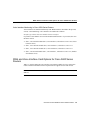
How to Use This Guide
•
Use Table 1-1 in Chapter 1, “Overview of Cisco WAN and Voice Interface Cards” to
identify the WAN and voice interface cards compatible with Cisco 3600 series routers
and their required release of Cisco IOS software.
•
Use Table 1-2 in Chapter 1, “Overview of Cisco WAN and Voice Interface Cards” to
identify the WAN and voice interface cards compatible with Cisco 2600 series routers
and their required release of Cisco IOS software.
•
Use Table 1-3 in Chapter 1, “Overview of Cisco WAN and Voice Interface Cards” to
identify the WAN interface cards compatible with the Cisco 1720 router and their
required release of Cisco IOS software.
•
Use Table 1-4 in Chapter 1, “Overview of Cisco WAN and Voice Interface Cards” to
identify the WAN interface cards compatible with Cisco 1600 series routers and their
required release of Cisco IOS software.
•
See Chapter 2, “Installing WAN and Voice Interface Cards in a Cisco Modular Router”
for instructions to install the WAN or voice interface card in a network module or in a
chassis card slot.
•
See Chapter 3, “Connecting WAN and Voice Interface Cards to a Network” for
instructions to connect the WAN or voice interface card to the network.
Audience
This publication is designed for the person installing the router, who should be familiar with
electronic circuitry and wiring practices and have experience as an electronic or
electromechanical technician.
viii
Cisco WAN Interface Cards Hardware Installation Guide
Organization
Organization
The major sections of this guide are as follows:
Chapter
Title
Description
Chapter 1
Overview of Cisco WAN and
Voice Interface Cards
Lists the WAN and voice interface card
options for Cisco modular routers,
discusses environmental requirements and
safety recommendations, and describes
how to prepare for connections between
networks and ports.
Chapter 2
Installing WAN and Voice
Interface Cards in a Cisco
Modular Router
Includes basic installation information for
installing network modules in Cisco 3600
series and Cisco 2600 series routers, and
for installing interface cards directly into
chassis slots on Cisco 2600 series,
Cisco 1600 series, and Cisco 1720
modular routers.
Chapter 3
Connecting WAN and Voice
Interface Cards to a Network
Provides basic hardware installation
information for connecting WAN and
voice interface cards to a network, and
reading interface cards LEDs.
Conventions
This publication uses the following conventions to convey instructions and information:
Convention
Description
boldface font
Commands and keywords.
italic font
Variables for which you supply values.
[
Keywords or arguments that appear within square brackets are optional.
]
{x | y | z}
A choice of required keywords appears in braces separated by vertical bars. You must
select one.
About This Guide ix
Conventions
Convention
Description
screen font
Examples of information displayed on the screen.
boldface screen font
Examples of information you must enter.
<
>
Nonprinting characters, for example passwords, appear in angle brackets.
[
]
Default responses to system prompts appear in square brackets.
Note
Means reader take note. Notes contain helpful suggestions or references to additional
information and material.
12
9
3
Timesaver This symbol means the described action saves time. You can save time
by performing the action described in the paragraph.
6
Caution This symbol means reader be careful. In this situation, you might do
something that could result in equipment damage or loss of data.
Warning This warning symbol means danger. You are in a situation that could cause
bodily injury. Before you work on any equipment, be aware of the hazards involved
with electrical circuitry and be familiar with standard practices for preventing accidents.
To see translations of the warnings that appear in this publication, refer to the
Regulatory Compliance and Safety Information document that accompanied this device.
Waarschuwing Dit waarschuwingssymbool betekent gevaar. U verkeert in een
situatie die lichamelijk letsel kan veroorzaken. Voordat u aan enige apparatuur gaat
werken, dient u zich bewust te zijn van de bij elektrische schakelingen betrokken
risico's en dient u op de hoogte te zijn van standaard maatregelen om ongelukken te
voorkomen. Voor vertalingen van de waarschuwingen die in deze publicatie
verschijnen, kunt u het document Regulatory Compliance and Safety Information
(Informatie over naleving van veiligheids- en andere voorschriften) raadplegen dat bij
dit toestel is ingesloten.
Varoitus Tämä varoitusmerkki merkitsee vaaraa. Olet tilanteessa, joka voi johtaa
ruumiinvammaan. Ennen kuin työskentelet minkään laitteiston parissa, ota selvää
sähkökytkentöihin liittyvistä vaaroista ja tavanomaisista onnettomuuksien
ehkäisykeinoista. Tässä julkaisussa esiintyvien varoitusten käännökset löydät laitteen
mukana olevasta Regulatory Compliance and Safety Information -kirjasesta
(määräysten noudattaminen ja tietoa turvallisuudesta).
x
Cisco WAN Interface Cards Hardware Installation Guide
Conventions
Convention
Description
Attention Ce symbole d'avertissement indique un danger. Vous vous trouvez dans une
situation pouvant causer des blessures ou des dommages corporels. Avant de travailler
sur un équipement, soyez conscient des dangers posés par les circuits électriques et
familiarisez-vous avec les procédures couramment utilisées pour éviter les accidents.
Pour prendre connaissance des traductions d’avertissements figurant dans cette
publication, consultez le document Regulatory Compliance and Safety Information
(Conformité aux règlements et consignes de sécurité) qui accompagne cet appareil.
Warnung Dieses Warnsymbol bedeutet Gefahr. Sie befinden sich in einer Situation,
die zu einer Körperverletzung führen könnte. Bevor Sie mit der Arbeit an irgendeinem
Gerät beginnen, seien Sie sich der mit elektrischen Stromkreisen verbundenen Gefahren
und der Standardpraktiken zur Vermeidung von Unfällen bewußt. Übersetzungen der in
dieser Veröffentlichung enthaltenen Warnhinweise finden Sie im Dokument Regulatory
Compliance and Safety Information (Informationen zu behördlichen Vorschriften und
Sicherheit), das zusammen mit diesem Gerät geliefert wurde.
Avvertenza Questo simbolo di avvertenza indica un pericolo. La situazione potrebbe
causare infortuni alle persone. Prima di lavorare su qualsiasi apparecchiatura, occorre
conoscere i pericoli relativi ai circuiti elettrici ed essere al corrente delle pratiche
standard per la prevenzione di incidenti. La traduzione delle avvertenze riportate in
questa pubblicazione si trova nel documento Regulatory Compliance and Safety
Information (Conformità alle norme e informazioni sulla sicurezza) che accompagna
questo dispositivo.
Advarsel Dette varselsymbolet betyr fare. Du befinner deg i en situasjon som kan føre
til personskade. Før du utfører arbeid på utstyr, må du vare oppmerksom på de
faremomentene som elektriske kretser innebærer, samt gjøre deg kjent med vanlig
praksis når det gjelder å unngå ulykker. Hvis du vil se oversettelser av de advarslene
som finnes i denne publikasjonen, kan du se i dokumentet Regulatory Compliance and
Safety Information (Overholdelse av forskrifter og sikkerhetsinformasjon) som ble
levert med denne enheten.
Aviso Este símbolo de aviso indica perigo. Encontra-se numa situação que lhe poderá
causar danos físicos. Antes de começar a trabalhar com qualquer equipamento,
familiarize-se com os perigos relacionados com circuitos eléctricos, e com quaisquer
práticas comuns que possam prevenir possíveis acidentes. Para ver as traduções dos
avisos que constam desta publicação, consulte o documento Regulatory Compliance
and Safety Information (Informação de Segurança e Disposições Reguladoras) que
acompanha este dispositivo.
About This Guide xi
Obtaining Service and Support
Convention
Description
¡Advertencia! Este símbolo de aviso significa peligro. Existe riesgo para su
integridad física. Antes de manipular cualquier equipo, considerar los riesgos que
entraña la corriente eléctrica y familiarizarse con los procedimientos estándar de
prevención de accidentes. Para ver una traducción de las advertencias que aparecen en
esta publicación, consultar el documento titulado Regulatory Compliance and Safety
Information (Información sobre seguridad y conformidad con las disposiciones
reglamentarias) que se acompaña con este dispositivo.
Varning! Denna varningssymbol signalerar fara. Du befinner dig i en situation som
kan leda till personskada. Innan du utför arbete på någon utrustning måste du vara
medveten om farorna med elkretsar och känna till vanligt förfarande för att förebygga
skador. Se förklaringar av de varningar som förkommer i denna publikation i
dokumentet Regulatory Compliance and Safety Information (Efterrättelse av
föreskrifter och säkerhetsinformation), vilket medföljer denna anordning.
Obtaining Service and Support
For service and support for a router purchased from a reseller, contact the reseller. Resellers
offer a wide variety of Cisco service and support programs, which are described in the
Cisco Information Packet that shipped with your router.
Note If you purchased your router from a reseller, you can also access Cisco Connection
Online (CCO) as a guest. CCO is Cisco Systems’ primary, real-time support channel. Your
reseller offers programs that include direct access to CCO’s services.
For service and support for a router purchased directly from Cisco, use CCO.
Cisco Connection Online
Cisco Connection Online (CCO) is Cisco Systems’ primary, real-time support channel.
Maintenance customers and partners can self-register on CCO to obtain additional
information and services.
xii
Cisco WAN Interface Cards Hardware Installation Guide
Cisco Connection Online
Available 24 hours a day, 7 days a week, CCO provides a wealth of standard and valueadded services to Cisco’s customers and business partners. CCO services include product
information, product documentation, software updates, release notes, technical tips, the
Bug Navigator, configuration notes, brochures, descriptions of service offerings, and
download access to public and authorized files.
CCO serves a wide variety of users through two interfaces that are updated and enhanced
simultaneously: a character-based version and a multimedia version that resides on the
World Wide Web (WWW). The character-based CCO supports Zmodem, Kermit,
Xmodem, FTP, and Internet e-mail, and it is excellent for quick access to information over
lower bandwidths. The WWW version of CCO provides richly formatted documents with
photographs, figures, graphics, and video, as well as hyperlinks to related information.
You can access CCO in the following ways:
•
•
•
•
•
WWW: http://www.cisco.com
WWW: http://www-europe.cisco.com
WWW: http://www-china.cisco.com
Telnet: cco.cisco.com
Modem: From North America, 408 526-8070; from Europe, 33 1 64 46 40 82. Use the
following terminal settings: VT100 emulation; databits: 8; parity: none; stop bits: 1; and
connection rates up to 28.8 kbps.
For a copy of CCO’s Frequently Asked Questions (FAQ), contact cco-help@cisco.com. For
additional information, contact cco-team@cisco.com.
Note If you are a network administrator and need personal technical assistance with a
Cisco product that is under warranty or covered by a maintenance contract, contact Cisco’s
Technical Assistance Center (TAC) at 800 553-2447, 408 526-7209, or tac@cisco.com. To
obtain general information about Cisco Systems, Cisco products, or upgrades, contact
800 553-6387, 408 526-7208, or cs-rep@cisco.com.
Please use CCO to obtain general information about Cisco Systems, Cisco products, or
upgrades. If CCO is not accessible, contact 800 553-6387, 408 526-7208, or
cs-rep@cisco.com.
About This Guide xiii
Ordering Documentation
Ordering Documentation
Cisco documentation and additional literature are available in a CD-ROM package, which
ships with your product. The Documentation CD-ROM, a member of the Cisco Connection
Family, is updated monthly. Therefore, it might be more current than printed
documentation. To order additional copies of the Documentation CD-ROM, contact your
local sales representative or call customer service. The CD-ROM package is available as a
single package or as an annual subscription. You can also access Cisco documentation on
the World Wide Web at http://www.cisco.com, http://www-china.cisco.com, or
http://www-europe.cisco.com.
If you are reading Cisco product documentation on the World Wide Web, you can submit
comments electronically. Click Feedback in the toolbar and select Documentation. After
you complete the form, click Submit to send it to Cisco. We appreciate your comments.
xiv
Cisco WAN Interface Cards Hardware Installation Guide
C H A PT E R
1
Overview of Cisco WAN and
Voice Interface Cards
This chapter provides an overview of Cisco WAN and voice interface cards used in Cisco
modular routers, and includes these sections:
•
•
•
•
•
Cisco 3600 Series Routers on page 1-1
Cisco 2600 Series Routers on page 1-7
Cisco 1720 Router on page 1-12
Cisco 1600 Series Routers on page 1-13
Safety and Regulatory Compliance Information on page 1-16
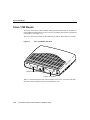
Cisco 3600 Series Routers
The Cisco 3600 series is a multifunction, modular platform that combines dial access,
routing, LAN-to-LAN services, and multiservice integration of voice, video, and data in the
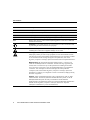
same device. The Cisco 3600 series includes the Cisco 3640 (see Figure 1-1) and Cisco
3620 routers (see Figure 1-2).
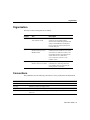
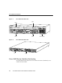
The Cisco 3640 has four network module slots; the Cisco 3620 has two slots. Each network
module slot accepts a variety of network module interface cards, supporting a variety of
LAN and WAN technologies.
Overview of Cisco WAN and Voice Interface Cards 1-1
Cisco 3600 Series Routers
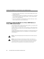
Figure 1-1
Cisco 3640 Router Rear View
Slot 2
Slot 3
2
BRI
NT1
B2
WO 2E W1
DO NOT INSTALL WAN INTERFACE
CARDS WITH POWER APPLIED
2W
ACT
SERIAL
ETHERNET 0
ACT
ETHERNET 1
LNK
STP
LNK
LNK
ACT
ETHERNET 1
AUI
EN
ACT
1
SERIAL
LNK
ACT
SEE MANUAL BEFORE INSTALLATION
H6551
B1
ACT
2E
W1
2W
NT1
3
AUI
EN
ETHERNET 0
INPUT 100-240VAC 50/60HZ 3.0-1.5 AMPS
Slot 1
Power supply
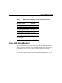
Cisco 3620 Router Rear View
H7238
Figure 1-2
Slot 0
2W
DO NOT INSTALL WAN INTERFACE
CARDS WITH POWER APPLIED
ETHERNET
ETH 1 1
Slot 1
ACT
ETHERNET 0
LNK
AUI
EN
LNK
SERIAL
LNK
ACT
LNK
ACT
1
ETHERNET 1
WO 2E W1
SERIAL
INSTALLATION
ACT
BRI
NT1
B2
SEE MANUAL BEFORE
ACT
B1
ACT
NT1
2E
W1
2W
AUI
EN
0
ETHERNET 0
Slot 0
Cisco 3600 Series Interface Numbering
Each individual network interface on a Cisco 3600 series router is identified by a slot
number and a unit number.
1-2
Cisco WAN Interface Cards Hardware Installation Guide
Cisco 3600 Series Interface Numbering
Slot Numbering
The Cisco 3600 series router chassis contains two or four slots in which you can install
modules. You can install any module into any available slot in the chassis.
As shown in Figure 1-1 and Figure 1-2, the slots are numbered as follows:
•
Slot 0 is at the bottom right (as viewed from the rear of the chassis), near the power
supply.
•
•
•
Slot 1 is at the bottom left.
Slot 2 is at the top right, above slot 0.
Slot 3 is at the top left, above slot 1.
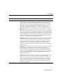
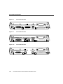
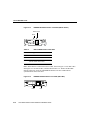
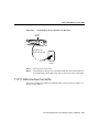
Some modules have two small slots, labeled W0 and W1, for WAN interface cards.
Figure 1-3 shows the W0 and W1 slots of the 2 Ethernet 2 WAN card slot
(2E 2-slot) module. You can install WAN interface cards into the small module slots (W0
and W1). Serial WAN interface cards can be installed into either slot, W0 or W1.
WAN Interface Card Slots
ETHERNET 1
Slot W0
WO
AUI
EN
LNK
ACT
ACT
STP
ILNK
Slot W1
2E
2W W1
ETHERNET 0
H8603
Figure 1-3
Unit Numbering
Cisco 3600 series routers unit numbers identify the interfaces on the modules and WAN
interface cards installed in the router. Unit numbers begin at 0 for each interface type, and
continue from right to left and (if necessary) from bottom to top. Modules and WAN
interface cards are identified by interface type, slot number, followed by a forward slash
(/), and then the unit number; for example, Ethernet 0/0.
Overview of Cisco WAN and Voice Interface Cards 1-3
Cisco 3600 Series Routers
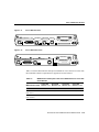
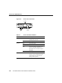
Figure 1-4 shows a router with a 2E 2-slot module in slots 0 and 1. Two serial WAN
interface cards are installed in the module in slot 0. One serial and one ISDN BRI WAN
interface card are installed in the module in slot 1.
As shown in Figure 1-4, the unit numbers are as follows:
•
•
•
•
•
•
•
•
Figure 1-4
Slot 0, Ethernet interface 0, referred to as Ethernet 0/0
Slot 0, Ethernet interface 1, referred to as Ethernet 0/1
Slot 0, serial interface 0, referred to as serial 0/0
Slot 0, serial interface 1, referred to as serial 0/1
Slot 1, Ethernet interface 0, referred to as Ethernet 1/0
Slot 1, Ethernet interface 1, referred to as Ethernet 1/1
Slot 1, serial interface 0, referred to as serial 1/0
Slot 1, BRI interface 0, referred to as BRI 1/0
Cisco 3600 Series Unit Numbers
BRI 1/0
Serial 1/0
Serial 0/1
Serial 0/0
2
WO 2E W1
2W
ACT
BRI
NT1
SERIAL
ETHERNET 1
ETHERNET 0
ETHERNET 1
ACT
LNK
STP
LNK
LNK
ACT
SERIAL
AUI
EN
ACT
1
LNK
ACT
SEE MANUAL BEFORE INSTALLATION
H8604
B2
ACT
B1
ACT
2E
W1
2W
NT1
3
AUI
EN
ETHERNET 0
INPUT 100-240VAC 50/60HZ 3.0-1.5 AMPS
Ethernet 1/1
1-4
Ethernet 1/0
Ethernet 0/1
Ethernet 0/0
Cisco WAN Interface Cards Hardware Installation Guide
Power supply
WAN and Voice Interface Card Options for Cisco 3600 Series Routers
Voice Interface Numbering in Cisco 3600 Series Routers
Voice interfaces are numbered differently from WAN interfaces described in the previous
section, “Unit Numbering.” Voice interfaces are numbered as follows:
interface type chassis slot/voice module slot/voice interface
If you have a four-channel voice network module installed in slot 1 of your router, the voice
interfaces will be:
•
Slot 1, voice network module slot 0, voice interface 0, referred to as voice 1/0/0 (closest
to chassis slot 0)
•
•
•
Slot 1, voice network module slot 0, voice interface 1, referred to as voice 1/0/1
Slot 1, voice network module slot 1, voice interface 0, referred to as voice 1/1/0
Slot 1, voice network module slot 1, voice interface 1, referred to as voice 1/1/1 (farthest
from chassis slot 0)
WAN and Voice Interface Card Options for Cisco 3600 Series
Routers
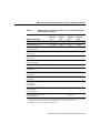
Table 1-1 lists the WAN and voice interface card options available for Cisco 3600 series
routers with their minimum software requirements for supported Cisco IOS releases.
Note Voice interface cards can only be used in voice network modules (NM-1V and
NM-2V).
Overview of Cisco WAN and Voice Interface Cards 1-5
Cisco 3600 Series Routers
Table 1-1
WAN and Voice Interface Card Options with Cisco IOS Releases for Cisco 3600 Series
Routers
Cisco IOS
Release
11.1
Cisco IOS
Release
11.2
Cisco IOS
Release
11.3
Cisco IOS
Release
11.3T
Cisco IOS
Release
12.0
Cisco IOS
Release
12.0T
1-Port Serial
(WIC-1T)
11.1(7)AA
11.2(5)P
11.3(1)
11.3(3)T
12.0(1)
12.0(1)T
1-Port ISDN BRI S/T1
with NT1
(WIC-1B-S/T)
–
11.2(4)XA
11.2(5)P
11.3(1)
11.3(3)T
12.0(1)
12.0(1)T
1-Port ISDN BRI U2
(WIC-1B-U)
–
11.2(4)XA
11/2(5)P
11.3(1)
11.3(3)T
12.0(1)
12.0(1)T
1-Port ISDN BRI S/T3
Leased Line
(WIC-1B-S/T-LL)
11.1(7)AA
11.2(9)P
–
11.3(3)T
–
12.0(1)T
1-Port 56/64-kbps
CSU/DSU
(WIC 1DSU-56K4)
–
11.2(12)P
–
11.3(3)T
–
12.0(1)T
1-Port T1
(WIC-1DSU-T1)
–
11.2(12)P
–
11.3(3)T
–
12.0(1)T
2-Port FXS voice/fax
interface (VIC-2FXS)
–
–
–
11.3(1)T
12.0(1)
12.0(1)T
2-Port FXO voice/fax
interface (VIC-2FXO)
–
–
–
11.3(1)T
12.0(1)
12.0(1)T
2-Port E&M voice/fax
interface (VIC-2E/M)
–
–
–
11.3(1)T
12.0(1)
12.0(1)T
2-Port FXO voice/fax
interface for use in
Europe
(VIC-2FXO-EU)
–
–
–
11.3(6)T
–
12.0(1)T
2-Port E&M voice/fax
interface for use in
Australia
(VIC-2FXO-M3)
–
–
–
11.3(6)T
–
12.0(1)T
WAN Interface Card
1-6
Cisco WAN Interface Cards Hardware Installation Guide
Cisco 2600 Series Routers
Table 1-1
WAN and Voice Interface Card Options with Cisco IOS Releases for Cisco 3600 Series
Routers (continued)
WAN Interface Card
2-Port ISDN BRI voice
interface
(VIC-2BRI-S/T-TE)
1
2
3
Cisco IOS
Release
11.1
Cisco IOS
Release
11.2
Cisco IOS
Release
11.3
Cisco IOS
Release
11.3T
Cisco IOS
Release
12.0
Cisco IOS
Release
12.0T
–
–
–
–
12.0(2)XD
–
Some ISDN service providers require an external Network Termination 1 (NT1) device to connect an ISDN S/T port to the
ISDN line. If your service provider requires this, you must provide the NT1.
The BRI U module does not require an external NT1.
Some ISDN service providers require an external Network Termination 1 (NT1) device to connect an ISDN S/T port to the
ISDN line. If your service provider requires this, you must provide the NT1.
Cisco 2600 Series Routers
The Cisco 2600 series is a multifunction platform that combines dial access, routing,
LAN-to-LAN services, and multiservice integration of voice, video, and data in the same
device. The Cisco 2600 series provides a low-entry price for medium-sized businesses. The
Cisco 2600 series has built-in LAN connections that provides a single or dual Ethernet port
(depending on model), one Ethernet, and one token ring port. Cisco 2600 series routers
also include one network module slot and two WAN slots that accept a variety of network
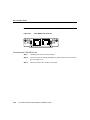
modules and interface cards. Figure 1-5 illustrates a Cisco 2611 router showing the
network module slot and WAN interface card slots.
Overview of Cisco WAN and Voice Interface Cards 1-7
Cisco 2600 Series Routers
Figure 1-5
Cisco 2600 Series Rear View
SERIAL 1
Cisco 2612
SERIAL 1
SERIAL 0
CONN
WIC
CONN 2A/S
SEE MANUAL BEFORE INSTALLATION
W1
SERIAL 0
CONN
CONN
100-240V– 1A
50/60 Hz 47 W
WIC
2T
SEE MANUAL BEFORE INSTALLATION
W0
Network
module
slot
LINK ETHERNET 0 ACT
CONSOLE
AUX
WAN interface
card slot W1
WAN interface
card slot W0
10344
LINK TOKEN RING 1 ACT
Cisco 2600 Series Interface Numbering
Each individual network interface on a Cisco 2600 series router is identified by a slot
number and a unit number.
Slot and Unit Numbering
The Cisco 2600 series router chassis contains one slot in which you can install a network
module. This is always slot 1.
Unit numbers identify the interfaces on the modules and WAN interface cards installed in
the router. Unit numbers begin at 0 for each interface type, and continue from right to left
and (if necessary) from bottom to top. Modules and WAN interface cards are identified by
interface type, slot number, followed by a forward slash (/), and then the unit number; for
example, Ethernet 0/0.
Figure 1-6 shows a router with a 2E 2-slot module in slot 1. One serial and one ISDN BRI
WAN interface card are installed in the module.
1-8
Cisco WAN Interface Cards Hardware Installation Guide
Cisco 2600 Series Interface Numbering
Figure 1-6
Cisco 2600 Series Unit Numbers
BRI 1/0
Serial 0/1
BRI
NT1
B2
Serial 0/0
WO
Cisco 2612
SERIAL
SEE MANUAL BEFORE INSTALLATION
CONN
LNK
ACT
ACT
LNK
AUI
EN
W1
SERIAL
W0
W0
ETHERNET 0
LINK TOKEN RING 0/0 ACT LINK
ETHERNET 0/0 ACT CONSOLE
Ethernet
1/1
100-240V– 1A
50/60 Hz 47 W
SERIAL
CONN
ETHERNET 1
16552
B1
ACT
NT1
Serial 1/0
2E
W1
2W
Ethernet
1/0
AUX
Ethernet Auxiliary
port
0/0
Token
Console
Ring 0/0
port
Note WAN interface card slots (built into the chassis) are always numbered as slot 0, even
if the interface card is installed in the slot labeled W1.
Figure 1-6 shows the following unit numbers:
•
•
•
•
•
•
•
•
First Ethernet interface, referred to as Ethernet 0/0
Token Ring interface, referred to as Token Ring 0/0
Slot W0, serial interface 0, referred to as serial 0/0
Slot W1, serial interface 1, referred to as serial 0/1
Slot 1, Ethernet interface 0, referred to as Ethernet 1/0
Slot 1, Ethernet interface 1, referred to as Ethernet 1/1
Slot 1, serial interface 0, referred to as serial 1/0
Slot 1, BRI interface 0, referred to BRI 1/0
Overview of Cisco WAN and Voice Interface Cards 1-9
Cisco 2600 Series Routers
Voice Interface Numbering in Cisco 2600 Series Routers
Voice interfaces are numbered differently from WAN interfaces described in the previous
section, “Slot and Unit Numbering.” Voice interfaces are numbered as follows:
interface type chassis slot/voice module slot/voice interface
If you have a four-channel voice network module installed in slot 1 of your router, the voice
interfaces will be:
•
Slot 1, voice network module slot 0, voice interface 0, referred to as voice 1/0/0 (closest
to the chassis WAN interface card slots)
•
•
•
Slot 1, voice network module slot 0, voice interface 1, referred to as voice 1/0/1
Slot 1, voice network module slot 1, voice interface 0, referred to as voice 1/1/0
Slot 1, voice network module slot 1, voice interface 1, referred to as voice 1/1/1 (farthest
from the chassis WAN interface card slots)
WAN and Voice Interface Card Options for Cisco 2600 Series
Routers
Table 1-2 lists the WAN and voice interface card options available for Cisco 2600 series
routers with their minimum software requirements for supported Cisco IOS releases.
Note Voice interface cards can only be used in voice network modules (NM-1V and
NM-2V).
1-10
Cisco WAN Interface Cards Hardware Installation Guide
WAN and Voice Interface Card Options for Cisco 2600 Series Routers
Table 1-2
WAN and Voice Interface Card Options with Cisco IOS Releases for
Cisco 2600 Series Routers
WAN Interface Card
Cisco IOS
Release
11.3
Cisco IOS
Release
11.3T
Cisco IOS
Release
12.0
Cisco IOS
Release
12.0T
1-Port Serial (WIC-1T)
11.3(2)XA
11.3(4)T
12.0(1)
12.0(1)T
2-Port Serial (WIC-2T)
11.3(2)XA
11.3(4)T
12.0(1)
12.0(1)T
2-Port Asynchronous/Synchronous
Serial (WIC-2A/S)
11.3(2)XA
11.3(4)T
12.0(1)
12.0(1)T
1-Port ISDN BRI S/T1
(WIC-1B-S/T)
11.3(2)XA
11.3(4)T
12.0(1)
12.0(1)T
1-Port ISDN BRI U2
(WIC-1B-U)
11.3(2)XA
11.3(4)T
12.0(1)
12.0(1)T
1-Port 56/64-kbps CSU/DSU
(WIC-1DSU-56K4)
11.3(2)XAT
11.3(4)T
–
12.0(1)T
1-Port T1/FT1 (WIC-1DSU-T1)
–
11.3(4)T
–
12.0(1)T
2-Port FXS voice/fax interface
(VIC-2FXS)
–
11.3(1)T
12.0(1)
12.0(1)T
2-Port FXO voice/fax interface
(VIC-2FXO)
–
11.3(1)T
12.0(1)
12.0(1)T
2-Port E&M voice/fax interface
(VIC-2E/M)
–
11.3(1)T
12.0(1)
12.0(1)T
2-Port FXO voice/fax interface for
use in Europe
(VIC-2FXO-EU)
–
11.3(6)T
–
12.0(1)T
2-Port E&M voice/fax interface for
use in Australia
(VIC-2FXO-M3)
–
11.3(6)T
–
12.0(1)T
2-Port ISDN BRI voice interface
(VIC-2BRI-S/T-TE)
–
–
12.0(2)XD
–
1
2
Some ISDN service providers require an external Network Termination 1 (NT1) device to connect an ISDN
S/T port to the ISDN line. If your service provider requires this, you must provide the NT1.
The BRI U module does not require an external NT1.
Overview of Cisco WAN and Voice Interface Cards 1-11
Cisco 1720 Router
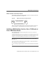
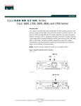
Cisco 1720 Router
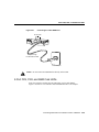
The Cisco 1720 router is a small, modular desktop router that links small- to medium-size
remote Ethernet and Fast Ethernet LANs over one to four WAN connections to regional and
central offices. (See Figure 1-7.)
The Cisco 1720 router includes one Fast Ethernet port and two WAN interface card slots.
Cisco 1720 Router Rear View
17369
Figure 1-7
Cisco
1720
WIC
0O
CONS
K
OLE
FDX
100
LNK
10/100
ETHE
RNET
AUX
Interface card slot WIC0
WIC
1 OK
+5, +1
2, -1
2 VD
C
Interface card slot WIC1
Table 1-3 lists WAN interface card options available for the Cisco 1720 router with their
minimum software requirements for Cisco IOS Release 12.0.
1-12
Cisco WAN Interface Cards Hardware Installation Guide
Cisco 1600 Series Routers
Table 1-3
WAN Interface Card Options with Cisco IOS Releases for the
Cisco 1720 Router
WAN Interface Card
Cisco IOS
Release
1-Port Serial (WIC-1T)
12.0(1)XA3
2-Port Serial (WIC-2T)
12.0(1)XA3
2-Port Asynchronous/Synchronous
Serial (WIC-2A/S)
12.0(1)XA3
1-Port ISDN BRI S/T (WIC-1B-S/T)
12.0(1)XA3
1-Port ISDN BRI U
(WIC-1B-U)
12.0(1)XA3
1-Port 56/64-kbps CSU/DSU
(WIC-1DSU-56K4)
12.0(1)XA3
1-Port T1/FT1 (WIC-1DSU-T1)
12.0(1)XA3
Cisco 1600 Series Routers
The Cisco 1600 series of access routers connect small offices with Ethernet LANs to the
public Internet and to a company’s internal intranet or corporate LAN through several WAN
connections. The Cisco 1600 series routers include the following models: the Cisco 1601,
Cisco 1602, Cisco 1603, Cisco 1604, and Cisco 1605-R. (See Figure 1-8 through
Figure 1-12.)
All Cisco 1600 series models include one Ethernet port, one built-in WAN port, and one
WAN interface card expansion slot for additional connectivity and flexibility.
Overview of Cisco WAN and Voice Interface Cards 1-13
Cisco 1600 Series Routers
Figure 1-8
Cisco 1601 Rear View
DO NOT INSTALL ANY WAN
MODULE WITH POWER ON
ETHERNET Ø
AUI
CONSOLE
RDY
LNK
Figure 1-9
SERIAL Ø
WIC
OK
FLASH PC CARD
14 VDC
H7183
10 BASE T
Cisco 1602 Rear View
DO NOT INSTALL ANY WAN
MODULE WITH POWER ON
ETHERNET Ø
AUI
CONSOLE
CARRIER
ALARM
LOOPBACK
LNK
Figure 1-10
SERIAL Ø 56K DSU/CSU
WIC
OK
FLASH PC CARD
14 VDC
H7184
10 BASE T
Cisco 1603 Rear View
DO NOT INSTALL ANY WAN
MODULE WITH POWER ON
LNK
1-14
ETHERNET Ø
AUI
ISDN BRI Ø S/T
OK
CONSOLE
WIC
OK
Cisco WAN Interface Cards Hardware Installation Guide
FLASH PC CARD
14 VDC
H7185
10 BASE T
Cisco 1600 Series Routers
Figure 1-11
Cisco 1604 Rear View
DO NOT INSTALL ANY WAN
MODULE WITH POWER ON
AUI
ISDN BRI Ø U
ISDN PHONE
NT 1
OK
LNK
Figure 1-12
CONSOLE
WIC
OK
FLASH PC CARD
14 VDC
H7186
ETHERNET Ø
10 BASE T
Cisco 1605-R Rear View
DO NOT INSTALL ANY WAN
MODULE WITH POWER ON
ETHERNET Ø
AUI
LNK
ETHERNET 1 10 BASE T
CONSOLE
LNK
WIC
OK OK
FLASH PC CARD
H10374
10 BASE T
14 VDC
Table 1-4 lists the WAN interface card options available for Cisco 1600 series routers with
their minimum software requirements for supported Cisco IOS releases.
Table 1-4
WAN Interface Card Options with Cisco IOS Releases for Cisco 1600
Series Routers
WAN Interface Card
Cisco IOS
Release 11.1
Cisco IOS
Release 11.2
Cisco IOS
Release 11.3
Cisco IOS
Release 11.3T
1-Port Serial (WIC-1T)
11.1(7)AA
11.2(5)P
11.3(1)
11.3(3)T
1-Port ISDN BRI U1
(WIC-1B-U)
11.1(7)AA
11.2(5)P
11.3(1)
11.3(3)T
1-Port ISDN BRI S/T2
(WIC-1B-S/T)
11.1(7)AA
11.2(5)P
11.3(1)
11.3(3)T
Overview of Cisco WAN and Voice Interface Cards 1-15
Safety and Regulatory Compliance Information
Table 1-4
WAN Interface Card Options with Cisco IOS Releases for Cisco 1600
Series Routers (continued)
Cisco IOS
Release 11.1
Cisco IOS
Release 11.2
Cisco IOS
Release 11.3
Cisco IOS
Release 11.3T
1-Port ISDN BRI S/T3
Leased Line
(WIC-1B-S/T-LL)
–
11.2(9)P
–
11.3(3)T
1-Port 56/64-kbps
CSU/DSU
(WIC-1DSU-56K4)
–
11.2(12)P
–
11.3(3)T
1-Port T1/FT1
(WIC-1DSU-T1)
–
11.2(12)P
–
11.3(3)T
WAN Interface Card
1
2
3
1-Port ISDN BRI U card is not available with Cisco 1603 or Cisco 1604 routers. The BRI U module does
not require an external NT1.
1-Port ISDN BRI S/T card is not available with Cisco 1603 or Cisco 1604 routers. Some ISDN service
providers require an external Network Termination 1 (NT1) device to connect an ISDN S/T port to the ISDN
line. If your service provider requires this, you must provide the NT1.
1-Port ISDN BRI S/T Leased-line card is only available with Cisco 1603 or Cisco 1604 routers. Some ISDN
service providers require an external Network Termination 1 (NT1) device to connect an ISDN S/T port to
the ISDN line. If your service provider requires this, you must provide the NT1.
Safety and Regulatory Compliance Information
This section lists safety warnings that you should be aware of before installing a network
module or interface card in the router. To see translated version of the safety warnings
contains in this guide, refer to the Cisco Regulatory Compliance and Safety Information
publication that accompanied your router.
This section includes:
•
•
•
•
•
1-16
Safety Recommendations on page 1-17
Safety with Electricity on page 1-18
Preventing Electrostatic Discharge Damage on page 1-19
FCC Class B Compliance on page 1-20
FCC Part 68 on page 1-20
Cisco WAN Interface Cards Hardware Installation Guide
Safety and Regulatory Compliance Information
•
•
•
Industry Canada CS-03 on page 1-22
European Commission on page 1-23
Call Progress Tone Settings on page 1-24
Overview of Cisco WAN and Voice Interface Cards 1-17
Safety and Regulatory Compliance Information
Safety Recommendations
Follow these guidelines to ensure general safety:
•
•
•
•
Keep the chassis area clear and dust-free during and after installation.
•
Wear safety glasses when working under any conditions that might be hazardous to your
eyes.
•
Do not perform any action that creates a potential hazard to people or makes equipment
unsafe.
Put the removed chassis cover in a safe place.
Keep tools away from walk areas where you or others could fall over them.
Do not wear loose clothing that could get caught in the chassis. Fasten your tie or scarf
and roll up your sleeves.
To see translations of the warnings that appear in this publication, refer to the Regulatory
Compliance and Safety Information document that accompanied your router.
1-18
Cisco WAN Interface Cards Hardware Installation Guide
Safety with Electricity
Safety with Electricity
Warning Before working on equipment that is connected to power lines, remove jewelry
(including rings, necklaces, and watches). Metal objects will heat up when connected to
power and ground and can cause serious burns or weld the metal object to the terminals.
Warning To avoid electric shock, do not connect safety extra-low voltage (SELV)
circuits to telephone-network voltage (TNV) circuits. LAN ports contain SELV circuits,
and WAN ports contain TNV circuits. Both LAN and WAN ports may use RJ-45
connectors. Use caution when connecting cables.
Warning Hazardous network voltages are present in WAN ports regardless of whether
power to the router is OFF or ON. To avoid electric shock, use caution when working near
WAN ports. When detaching cables, detach the end away from the router first.
Warning Before opening the chassis, disconnect the telephone-network cables to avoid
contact with telephone-network voltages.
Warning Do not work on the system or connect or disconnect cables during periods of
lightning activity.
Warning Do not touch the power supply when the power cord is connected. For systems
with a power switch, line voltages are present within the power supply even when the
power switch is OFF and the power cord is connected. For systems without a power
switch, line voltages are present within the power supply when the power cord is
connected.
Follow these guidelines when working on equipment powered by electricity:
•
Locate the emergency power-off switch in the room in which you are working. Then, if
an electrical accident occurs, you can quickly shut the power OFF.
•
Before working on the router, turn OFF the power and unplug the power cord.
Overview of Cisco WAN and Voice Interface Cards 1-19
Safety and Regulatory Compliance Information
•
Disconnect all power before doing the following:
— Installing or removing a router chassis
— Working near power supplies
•
•
•
Do not work alone if potentially hazardous conditions exist.
•
If an electrical accident occurs, proceed as follows:
Never assume that power is disconnected from a circuit. Always check.
Look carefully for possible hazards in your work area, such as moist floors, ungrounded
power extension cables, and missing safety grounds.
— Use caution; do not become a victim yourself.
— Turn OFF power to the router.
— If possible, send another person to get medical aid. Otherwise, determine the
condition of the victim and then call for help.
— Determine if the person needs rescue breathing or external cardiac compressions;
then take appropriate action.
Preventing Electrostatic Discharge Damage
Electrostatic discharge (ESD) can damage equipment and impair electrical circuitry. It
occurs when electronic printed circuit cards are improperly handled and can result in
complete or intermittent failures. Always follow ESD prevention procedures when
removing and replacing cards. Ensure that the router chassis is electrically connected to
earth ground. Wear an ESD-preventive wrist strap, ensuring that it makes good skin contact.
Connect the clip to an unpainted surface of the chassis frame to safely channel unwanted
ESD voltages to ground. To properly guard against ESD damage and shocks, the wrist strap
and cord must operate effectively. If no wrist strap is available, ground yourself by touching
the metal part of the chassis.
Caution For safety, periodically check the resistance value of the antistatic strap, which
should be between 1 and 10 megohm (Mohm).
1-20
Cisco WAN Interface Cards Hardware Installation Guide
FCC Class B Compliance
FCC Class B Compliance
The equipment described in this document generates and may radiate radio-frequency
energy. If it is not installed in accordance with Cisco’s installation instructions, it may cause
interference with radio and television reception. This equipment has been tested and found
to comply with the limits for a Class B digital device in accordance with the specifications
in part 15 of the FCC rules. These specifications are designed to provide reasonable
protection against such interference in a residential installation. However, there is no
guarantee that interference will not occur in a particular installation.
You can determine whether your equipment is causing interference by turning it off. If the
interference stops, it was probably caused by the Cisco equipment or one of its peripheral
devices. If the equipment causes interference to radio or television reception, try to correct
the interference by using one or more of the following measures:
•
•
•
•
Turn the television or radio antenna until the interference stops.
Move the equipment to one side or the other of the television or radio.
Move the equipment farther away from the television or radio.
Plug the equipment into an outlet that is on a different circuit from the television or
radio. (That is, make certain the equipment and the television or radio are on circuits
controlled by different circuit breakers or fuses.)
Modifications to this product not authorized by Cisco Systems, Inc. could void the FCC
approval and negate your authority to operate the product.
FCC Part 68
This equipment complies with Part 68 of the FCC rules. On the front panel of this
equipment is a label that contains, among other information, the FCC registration number.
If requested, you must provide this information to the telephone company.
An FCC-compliant cord and modular plug is provided with this equipment. This equipment
is designed for connection to the telephone network or premises wiring using a compatible
modular jack that is Part 68 compliant. See the installation instructions
for details.
This equipment cannot be used on telephone company-provided coin
service. Connection to party line service is subject to state tariffs.
Overview of Cisco WAN and Voice Interface Cards 1-21
Safety and Regulatory Compliance Information
If this equipment causes harm to the telephone network, the telephone company will notify
you in advance that it may be necessary to temporarily discontinue service. If advance
notice is not practical, the telephone company will notify you as soon as possible. Also, you
will be advised of your right to file a complaint with the FCC.
The telephone company may make changes in its facilities, equipment, operations, or
procedures that could affect the operation of this equipment. If this happens, the telephone
company will provide advance notice for you to make the necessary modifications to
maintain uninterrupted service.
This device does not include any upgradeable parts.
This equipment uses Universal Service Order Code (USOC) jacks as listed in Table 1-5.
Table 1-5
1-22
WAN Interface Card USOC Jacks
Facility
Interface Code
Service Order
Code
Jack Type
Cisco Product Number
WIC-1DSU-SW56K4
04DU5-56
6.0N
RJ-48S
WIC-1B-S/T
WIC-1ST-CH
02IS5
6.0N
RJ-49C
VIC-2BRI-S/T
02IS5
6.0N
RJ-49C
WIC-1B-U
WIC-U-CH
02IS5
6.0N
RJ-49C
WIC-1DSU-T1
04DU9-BN
04DU9-DN
04DU9-1KN
04DU9-1SN
6.0N
6.0N
6.0N
6.0N
RJ48C
RJ48C
RJ48C
RJ48C
Cisco WAN Interface Cards Hardware Installation Guide
Industry Canada CS-03
Industry Canada CS-03
The following information applies to models used in Canada.
Ringer Equivalence Number
The Ringer Equivalence Number (REN) assigned to each terminal device provides an
indication of the maximum number of terminals allowed to be connected to a telephone
interface. The termination on an interface may consist of any combination of devices,
subject only to the requirement that the sum of the Ringer Equivalence Numbers of all the
devices does not exceed 5.
Equipment Attachment Limitations
The Industry Canada label identifies certified equipment. This certification means that the
equipment meets certain telecommunications network protective, operational, and safety
requirements as prescribed in the appropriate Terminal Equipment Technical Requirement
Documents. The Department does not guarantee the equipment will operate to the user’s
satisfaction.
Before installing this equipment, users should ensure that it is permissible to be connected
to the facilities of the local telecommunications company. The equipment must also be
installed using an acceptable method of connection. The customer should be aware that
compliance with the above conditions may not prevent degradation of service in some
situations.
Repairs to certified equipment should be coordinated by a representative designated by the
supplier. Any repairs or alterations made by the user to this equipment, or equipment
malfunctions, may give the telecommunications company cause to request the user to
disconnect the equipment.
Users should ensure for their own protection that the electrical ground connections of the
power utility, telephone lines, and internal metallic water pipe system, if present, are
connected together. This precaution may be particularly important in rural areas.
Caution Users should not attempt to make connections themselves, but should contact the
appropriate electric inspection authority, or electrician, as appropriate.
Overview of Cisco WAN and Voice Interface Cards 1-23
Safety and Regulatory Compliance Information
See Table 1-6 for additional information.
Table 1-6
Canadian Operating Information
Interface
Connecting
Method
Ringer
Equivalence
Number
VIC-2FXO loop-start trunk interface
CA11, CA48
0.5
VIC-2FXO ground-start trunk interface
CA11, CA48
0.5
VIC-2FXS on-premises station interface
CA11, CA48
0.5
VIC-2E/M on-premises E&M interface
CA11, CA48
0.5
VIC-2BRI-S/T on-premises E&M interface
CB-1B
0.0
Australian Communications Authority Technical Standard 031
The following warning applies to the 2-Port ISDN BRI voice interface card (Cisco product
number VIC-2BRI-S/T-TE).
Warning This equipment will be inoperable when mains power fails.
European Commission
The VIC-2FXO-EU voice interface card has been approved to Common Technical
Regulation (CTR) 21 for pan-European single-terminal connection to the PSTN. However,
because of differences among the PSTNs in different countries, this approval does not, in
itself, give unconditional assurance of successful operation on every PSTN network
termination point.
In the event of problems, you should first contact your equipment supplier.
1-24
Cisco WAN Interface Cards Hardware Installation Guide
Call Progress Tone Settings
Call Progress Tone Settings
VIC-2FXO voice interface cards are available in several versions with interfaces intended
for different geographical regions.
There are no hardware settings for connecting these voice interface cards to the public
switched telephone network. To comply with national regulatory requirements, you must
set call progress tones to the values shown in Table 1-7, using the Cisco IOS cptone
command.
To set call progress tones for a voice port, enter the following commands in global
configuration mode:
Router(config)# voice-port slot-number/subunit-number/port
Router(config-voice-port)# cptone setting
Table 1-7
Call Progress Tone Settings
Country
Setting
Compliance
Australia
australia
ACA TS 002/TS 003
Canada
northamerica
Industry Canada CS-03
Denmark
dk
–
Germany
de
BAPT 223 ZV 5:July 1996
Great Britain
gb
PD 7020:1996
Hong Kong
hk
HK Telecom CR01 and CR02
Luxembourg
lu
–
Mexico
northamerica
NOM-036-SCT1-1993
Sweden
se
SS 63 63 39
Switzerland
ch
BAKOM 337/2.2
Thailand
th
PTT Subscriber Line Standards
United States
northamerica
FCC Part 68
Overview of Cisco WAN and Voice Interface Cards 1-25
Safety and Regulatory Compliance Information
1-26
Cisco WAN Interface Cards Hardware Installation Guide
C H A PT E R
2
Installing WAN and Voice
Interface Cards in a Cisco
Modular Router
This chapter describes how to install WAN and voice interface cards in Cisco 3600 series,
2600 series, 1600 series, and Cisco 1720 modular routers, and contains the following
sections:
•
•
Required Tools and Equipment on page 2-1
•
•
Before Installing a Voice Interface Card on page 2-5
•
Installing a WAN Interface Card in a Cisco 1720 Router or Cisco 1600 Series Router on
page 2-9
Installing a Network Module in a Cisco 3600 Series or Cisco 2600 Series Router on
page 2-2
Installing a WAN or Voice Interface Card in a Network Module or Chassis Slot on page
2-6
Required Tools and Equipment
In addition to the WAN interface card and the router, you need the following items to install
and connect your card:
•
•
Number 2 Phillips screwdriver.
Appropriate connecting cable—The cable type required for each card is described in the
section for that card. For more information on the types of cables that can be used with
the cards, See the online document Cisco Modular Router Cable Specifications on the
Documentation CD-ROM that accompanied your router package, or on Cisco
Connection Online.
Installing WAN and Voice Interface Cards in a Cisco Modular Router 2-1
Installing a Network Module in a Cisco 3600 Series or Cisco 2600 Series Router
•
Asynchronous modem (serial card only)—Used to connect the WAN interface card to
an analog telephone line.
•
Synchronous modem, channel service unit/data service unit (DSU/CSU), or other data
circuit-terminating equipment (DCE) (serial card only)—Used to connect the WAN
interface card to a digital WAN line.
•
External NT1 (ISDN BRI S/T and ISDN BRI S/T Leased-Line cards only)—Used to
connect the WAN interface card to an ISDN interface.
Installing a Network Module in a Cisco 3600 Series or
Cisco 2600 Series Router
This section describes how to install a network module (for WAN or voice interface cards)
in a Cisco 3600 series or Cisco 2600 series router.
To install a WAN or voice interface card in a network module or to install a WAN interface
card in a Cisco 2600 series chassis slot, see the “Before Installing a Voice Interface Card”
section on page 2-5.
To install a WAN interface card in a Cisco 1720 router or Cisco 1600 series router, see the
“Installing a WAN Interface Card in a Cisco 1720 Router or Cisco 1600 Series Router”
section on page 2-9.
Warning Only trained and qualified personnel should be allowed to install or replace this
equipment.
Warning Before performing any of the following procedures, ensure that power is
removed from the DC circuit. To ensure that all power is OFF, locate the circuit breaker
on the panel board that services the DC circuit, switch the circuit breaker to the OFF
position, and tape the switch handle of the circuit breaker in the OFF position.
2-2
Cisco WAN Interface Cards Hardware Installation Guide
Installing a Network Module in a Cisco 3600 Series or Cisco 2600 Series Router
Warning You can install modules in the chassis either before or after mounting the
router. If possible, install the modules with the router in the position that provides the best
access to the rear panel. You can install any module into any available slot in the chassis.
Caution Do not insert a module into a slot when power is ON or network cables are
connected.
Note Do not install an ISDN BRI WAN interface card or an ISDN BRI network module
in the same chassis as an ISDN PRI network module. This configuration is not supported.
To install a network module in a Cisco 3600 series or Cisco 2600 series router:
Step 1
Power OFF the router. However, to channel ESD voltages to ground, do not
unplug the power cable. Remove all network interface cables, including
telephone cables, from the rear panel.
Step 2
Use a Phillips or flat-blade screwdriver to remove the blank filler panel from the
slot where you plan to install the module. Save the filler panel for possible future
use.
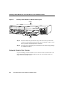
Step 3
Align the module with the guides in the chassis and slide it gently into the slot.
(See Figure 2-1.)
Installing WAN and Voice Interface Cards in a Cisco Modular Router 2-3
Installing a Network Module in a Cisco 3600 Series or Cisco 2600 Series Router
Figure 2-1
Installing a Network Module in a Modular Router (typical)
Router
2
B1
ACT
2E
W1
2W
NT1
3
BRI
NT1
B2
WO
0
SERIAL
AUI
EN
B1
DO NOT INSTALL WAN INTERFACE
CARDS WITH POWER APPLIED
BRI
S/T
B2
H7481
LNK
2E
W1
2W
WO
ACT
ETHERNET 1
AUI
EN
LNK
ACT
ETHERNET 0
LNK
ETHERNET 1
ACT
1
LNK
ACT
SEE MANUAL BEFORE INSTALLATION
INPUT 100-240VAC 50/60HZ 3.0-1.5 AMPS
ETHERNET 0
Module
Step 4
Push the module into place until the edge connector is securely seated in the
connector on the motherboard. Ensure that each of the module’s captive screws
lines up with its corresponding hole in the chassis.
Step 5
Secure the captive mounting screws into the holes of the chassis using a Phillips
or flat-blade screwdriver.
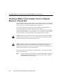
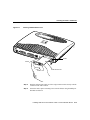
Network Module Filler Panels
If you are installing a network module in a Cisco 3600 series router, and the router is not
fully configured with modules, you must fill the open slots with slot filler panels (see
Figure 2-2) to ensure proper airflow.
2-4
Cisco WAN Interface Cards Hardware Installation Guide
Before Installing a Voice Interface Card
Network Module Slot Filler Panel
H6552
Figure 2-2
Before Installing a Voice Interface Card
This section contains additional information that you need before installing a voice
interface card in a voice network module installed in a Cisco 3600 series or Cisco 2600
series router
A voice connection requires both a voice network module and a voice interface card. Voice
interface cards are installed in voice network modules only, and do not install directly into
the router chassis. At least one other network module or WAN interface card must be
installed in the router to provide the connection to the IP LAN or WAN. For instructions on
how to install a network module, see the “Installing a Network Module in a Cisco 3600
Series or Cisco 2600 Series Router” section on page 2-2.
Caution Although voice interface cards physically resemble WAN interface cards, voice
and WAN interface cards are not interchangeable. Voice interface cards cannot be
installed in a WAN interface card slot or a two-slot network module, and WAN interface
cards cannot be installed in a voice network module.
For instructions on inserting a voice interface card into a voice network module, see the
“Installing a WAN or Voice Interface Card in a Network Module or Chassis Slot” section
on page 2-6.
Installing WAN and Voice Interface Cards in a Cisco Modular Router 2-5
Installing a WAN or Voice Interface Card in a Network Module or Chassis Slot
Installing a WAN or Voice Interface Card in a Network
Module or Chassis Slot
This section describes how to install a WAN or voice interface card in a two-slot network
module (used in Cisco 3600 series and Cisco 2600 series routers), or how to install a WAN
interface card in a Cisco 2600 series chassis slot (see Figure 2-3).
If you need to install the network module, see the “Installing a Network Module in a
Cisco 3600 Series or Cisco 2600 Series Router” section on page 2-2.
You can install WAN interface cards either before or after mounting the router, whichever
is more convenient. Similarly, you can install WAN or voice interface cards in the network
module either before or after installing the network module in the router chassis.
Caution WAN and voice interface cards do not support online insertion and removal (hot
swapping). Before inserting a card into the network module or router chassis, you must
turn OFF electrical power and disconnect network cables.
Caution Although voice interface cards physically resemble WAN interface cards, voice
and WAN interface cards are not interchangeable. Voice interface cards cannot be
installed in a WAN interface card slot or a two-slot network module, and WAN interface
cards cannot be installed in a voice network module.
Follow this procedure to install cards in a network module or a Cisco 2600 series WAN
interface card chassis slot:
Step 1
2-6
Turn OFF power to the router. However, to channel ESD voltages to ground, do
not unplug the power cable. Remove all network interface cables, including
telephone cables, from the rear panel.
Cisco WAN Interface Cards Hardware Installation Guide
Installing a WAN or Voice Interface Card in a Network Module or Chassis Slot
The following warning applies to routers that use a DC power supply.
Warning Before performing any of the following procedures, ensure that power is
removed from the DC circuit. To ensure that all power is OFF, locate the circuit breaker
on the panel board that services the DC circuit, switch the circuit breaker to the OFF
position, and tape the switch handle of the circuit breaker in the OFF position.
Note If you are installing a single WAN interface card in a Cisco 2600 series
router, use slot W0 first. (See Figure 2-3.)
The Cisco 2600 series router first checks slot W0 before it checks slot W1. If you
fill slot W1 while leaving slot W0 vacant, your router configuration could be
affected.
Step 2
Using either a number 2 Phillips screwdriver or a small flat-blade screwdriver to
remove the blank filler panel from the network module slot or chassis card slot
where you plan to install the card. Save the filler panel for future use.
Note The voice network module slots are numbered V0, on the right, and V1,
on the left.
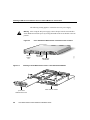
Step 3
Align the card with the guides in the two-slot network module or WAN interface
card slot and slide it gently into the slot. (Figure 2-4 shows a 1-port serial WAN
interface card.)
Step 4
Push the card into place until you feel its edge connector mate securely with the
connector in the two-slot network module or WAN interface card slot.
Step 5
Fasten the card’s captive mounting screws into the holes in the network module
faceplate or WAN interface card slot, using the Phillips or flat-blade screwdriver.
Step 6
If the router was previously running, reinstall the network interface cables and
turn ON power to the router.
Installing WAN and Voice Interface Cards in a Cisco Modular Router 2-7
Installing a WAN or Voice Interface Card in a Network Module or Chassis Slot
The following warning applies to routers that use a DC power supply:
Warning After wiring the DC power supply, remove the tape from the circuit breaker
switch handle and reinstate power by moving the handle of the circuit breaker to the ON
position.
Figure 2-3
Cisco 2600 Series WAN Interface Card Chassis Slot Locations
SERIAL 1
Cisco 2612
SERIAL 1
SERIAL 0
CONN
WIC
CONN 2A/S
SERIAL 0
CONN
SEE MANUAL BEFORE INSTALLATION
CONN
100-240V– 1A
50/60 Hz 47 W
WIC
2T
SEE MANUAL BEFORE INSTALLATION
W1
W0
LINK TOKEN RING 1 ACT
CONSOLE
AUX
10344
WAN interface
card slot W1
WAN interface
card slot W0
Network
module
slot
Figure 2-4
LINK ETHERNET 0 ACT
Installing a Serial WAN Interface Card in a Two-Slot Network Module
ACT
LNK
ACT
LNK
WO
ETH 1
ETH 0
AUI
EN
SERIA
L
2-slot network module
1-port serial
WAN interface card
2-8
Cisco WAN Interface Cards Hardware Installation Guide
H7533
2E
2W W1
WAN Interface Card Filler Panels
WAN Interface Card Filler Panels
If any interface card slot (on the network module or chassis) is unoccupied, install a filler
panel to enable proper airflow. (See Figure 2-5.)
Figure 2-5
WAN or Voice Interface Card Slot Filler Panel
H6649
DO NOT INSTALL WAN INTERFACE
CARDS WITH POWER APPLIED
When you have finished installing interface cards in the network module or chassis slots,
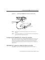
proceed to Chapter 3, “Connecting WAN and Voice Interface Cards to a Network.”
Installing a WAN Interface Card in a Cisco 1720 Router or
Cisco 1600 Series Router
This section describes how to install a WAN interface card in a Cisco 1720 router or
Cisco 1600 series router.
To install a WAN interface card in a Cisco 3600 series or Cisco 2600 series router, see the
“Installing a Network Module in a Cisco 3600 Series or Cisco 2600 Series Router” section
on page 2-2, or the “Before Installing a Voice Interface Card” section on page 2-5.
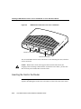
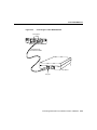
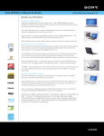
Note The Cisco 1720 router contains two WAN interface card slots, WIC0 and WIC1.
(See Figure 2-6.)
The router first checks slot WIC0 before it checks slot WIC1. A single card installed in
WIC1 could affect your router configuration.
If you are installing a single WAN interface card in the router, install the card in the WIC0
slot.
Installing WAN and Voice Interface Cards in a Cisco Modular Router 2-9
Installing a WAN Interface Card in a Cisco 1720 Router or Cisco 1600 Series Router
WAN Interface Card Slots in the Cisco 1720 Router
17369
Figure 2-6
Cisco
1720
WIC
0O
CONS
K
OLE
FDX
100
LNK
10/100
ETHE
RNET
AUX
Interface card slot WIC0
WIC
1 OK
+5, +1
2, -1
2 VD
C
Interface card slot WIC1
You can install WAN interface cards either before or after mounting the router, whichever
is more convenient.
Caution WAN interface cards do not support online insertion and removal (hot
swapping). Before inserting a WAN interface card into the router chassis, you must turn
OFF electrical power and disconnect network cables.
Inserting the Card in the Router
Note The figures in this section show a Cisco 1600 series router, but the installation
sequence described applies to the Cisco 1720 router as well as Cisco 1600 series routers.
2-10
Cisco WAN Interface Cards Hardware Installation Guide
Inserting the Card in the Router
Follow this procedure to install the WAN interface card in the router:
Step 1
On the Cisco 1720 router, turn the power switch to the STANDBY position, and
disconnect the power cable from the power socket on the rear panel.
On a Cisco 1600 series router, turn OFF power to the router. However, to channel
ESD voltages to ground, do not unplug the power cable.
Step 2
Remove all network interface cables, including telephone cables, from the rear
panel.
Step 3
Use either a number 2 Phillips screwdriver or a small flat-blade screwdriver to
remove the filler panel from the WAN interface card slot. (See
Figure 2-7.) Save the filler panel for future use.
Installing WAN and Voice Interface Cards in a Cisco Modular Router 2-11
Installing a WAN Interface Card in a Cisco 1720 Router or Cisco 1600 Series Router
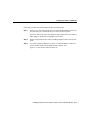
Removing the Slot Cover
H7179
Figure 2-7
DO NO
MODU T INSTAL
L
LE W
ITH POANY WAN
WER
ON
WAN interface card slot cover
Step 4
2-12
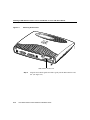
Align the card with the guides and slide it gently into the WAN interface card
slot. (See Figure 2-8.)
Cisco WAN Interface Cards Hardware Installation Guide
Inserting the Card in the Router
Inserting a WAN Interface Card
H7180
Figure 2-8
LN K
W IC
OK O
K
Guides
Guides
WAN interface card
Step 5
Push the card into place until you feel its edge connector mate securely with the
connector in the router chassis.
Step 6
Fasten the card’s captive mounting screws into the chassis using the Phillips or
flat-blade screwdriver.
Installing WAN and Voice Interface Cards in a Cisco Modular Router 2-13
Installing a WAN Interface Card in a Cisco 1720 Router or Cisco 1600 Series Router
Note If any WAN interface card slot on the chassis is unoccupied, install a filler
panel to enable proper airflow.
Step 7
If the router was previously running, reinstall the network interface cables and
turn ON power to the router.
After installing the WAN interface card into the router, proceed to Chapter 3, “Connecting
WAN and Voice Interface Cards to a Network.”
2-14
Cisco WAN Interface Cards Hardware Installation Guide
C H A PT E R
3
Connecting WAN and Voice
Interface Cards to a Network
This chapter describes how to connect Cisco WAN interface cards to a network and
contains the following sections:
•
•
•
•
•
•
Serial Cards on page 3-1
1-Port ISDN BRI Cards on page 3-6
1-Port ISDN BRI S/T Leased-Line Card on page 3-15
1-Port 56/64-kbps DSU/CSU Card on page 3-18
1-Port T1/FT1 DSU/CSU Card on page 3-20
Voice Interface Cards on page 3-23
Serial Cards
This section describes the following Cisco WAN interface cards:
•
•
1-Port and 2-Port Serial Cards on page 3-1
2-Port Asynchronous/Synchronous Serial Card on page 3-3
1-Port and 2-Port Serial Cards
The 1-port serial WAN interface card, shown in Figure 3-1, and the 2-port serial WAN
interface cards, shown in Figure 3-2, provide an EIA/TIA-232, EIA/TIA-449, V.35, X.21,
data terminal equipment/data communications equipment (DTE/DCE), EIA-530 DTE, or
nonreturn to zero/nonreturn to zero inverted (NRZ/NRZI) serial interface to a Cisco
modular router.
Connecting WAN and Voice Interface Cards to a Network 3-1
Serial Cards
Note In Cisco 3600 and Cisco 2600 series routers, the 1-port and 2-port serial WAN
interface cards support synchronous data rates up to 2.048 mbps.
In the Cisco 1720 router, the 1-port and 2-port serial WAN interface cards support both
asynchronous and synchronous data rates up to 2.048 mbps.
In Cisco 1600 series routers, the 1-port serial WAN interface cards support asynchronous
data rates up to 115.2 kbps, and synchronous data rates up to 2.048 mbps.
Each serial card has one LED, labeled CONN for each port, which lights when the serial
port is connected. When the port is in DTE mode, the CONN LED indicates that Data Send
Ready (DSR), Data Carrier Detect (DCD), and Clear To Send (CTS) have been detected.
When the port is in DCE mode, it indicates that Data Terminal Ready (DTR) and Ready To
Send (RTS) have been detected.
1-Port Serial WAN Interface Card—Front Panel
Serial port
CONN LED
CONN
3-2
SERIAL
H7212
Figure 3-1
Cisco WAN Interface Cards Hardware Installation Guide
2-Port Asynchronous/Synchronous Serial Card
Figure 3-2
2-Port Serial WAN Interface Card—Front Panel
Serial ports
SERIAL 0
CONN
CONN
WIC
2T
SEE MANUAL BEFORE INSTALLATION
H11496
SERIAL 1
CONN LEDs
2-Port Asynchronous/Synchronous Serial Card
The 2-port asynchronous/synchronous (A/S) WAN interface card, shown in Figure 3-3,
provides an EIA/TIA-232, EIA/TIA-449, V.35, X.21, DTE/DCE, EIA-530, or EIA-530A
serial interface to a Cisco modular router. The 2-port A/S WAN interface card supports
asynchronous data rates up to 133.6 kbps and synchronous data rates up to 128 kbps.
Figure 3-3
2-Port A/S Serial WAN Interface Card—Front Panel
Serial ports
SERIAL 0
CONN
SEE MANUAL BEFORE INSTALLATION
WIC
CONN 2A/S
H11497
SERIAL 1
CONN LEDs
Connecting WAN and Voice Interface Cards to a Network 3-3
Serial Cards
Connecting Serial WAN Interface Cards to a Network
The 1-port and 2-port serial WAN interface cards use a universal high-density 60-pin
receptacle. The serial cable attached to this receptacle determines the port’s electrical
interface type and mode (DTE or DCE).
Types of Serial Cables
Six types of serial cables (also called serial adapter cables or serial transition cables) are
available from Cisco Systems:
•
•
•
•
•
•
EIA/TIA-232 serial cable assembly
EIA/TIA-449 serial cable assembly
V.35 serial cable assembly
X.21 serial cable assembly
EIA/TIA-530 serial cable assembly
EIA/TIA-530A serial cable assembly
For more information on serial cable assemblies, refer to the hardware installation guide
that accompanied your router package.
All serial cables provide a universal plug at the interface card end. The network end of each
cable provides the physical connectors most commonly used for the interface. For example,
the network end of the EIA/TIA-232 serial cable is a DB-25 connector, the most widely
used EIA/TIA-232 connector.
All serial interface types except EIA-530 are available in DTE or DCE format: DTE with a
plug connector at the network end and DCE with a receptacle at the network end. V.35 is
available in either mode with either gender at the network end. EIA-530 is available in DTE
only.
3-4
Cisco WAN Interface Cards Hardware Installation Guide
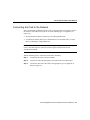
Connecting the Card to the Network
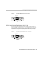
Connecting the Card to the Network
After you install the serial WAN interface card, use the appropriate serial cable to connect
the interface card’s DB-60 serial port to one of the following types of equipment (see
Figure 3-4):
•
•
An asynchronous modem, if connecting to an analog telephone line
A synchronous modem, data service unit/channel service unit (DSU/CSU), or other
DCE, if connecting to a digital WAN line
Note Cisco 3600 and Cisco 2600 series routers support only synchronous modems; the
Cisco 1720 router and Cisco 1600 series routers support both synchronous and
asynchronous modems.
Take the following steps to connect the serial card to the WAN:
Step 1
Confirm that the router is still turned OFF.
Step 2
Connect one end of the appropriate serial cable to the card’s DB-60 port.
Step 3
Connect the other end of the cable to the appropriate type of equipment, as
shown in Figure 3-4.
Connecting WAN and Voice Interface Cards to a Network 3-5
1-Port ISDN BRI Cards
Figure 3-4
Connecting the Serial WAN Port to a Modem or DSU/CSU
Synchronous serial
port (DB-60)
CONN LED
CONN
SERIAL
Serial transition
cable
EIA/TIA-232, EIA/TIA-449, V.35,
X.21, or EIA-530 connector
H7370
CSU/DSU or
other DCE
Step 4
Turn ON power to the router by pressing the power switch to the ON ( | )
position.
Step 5
Check that the CONN LED goes on, which indicates that the card’s serial port
detects the WAN serial connection.
If you have additional cards to install, proceed to the appropriate section(s) in this manual.
When you have finished all installations, see the software configuration guide that shipped
with your hardware.
1-Port ISDN BRI Cards
This section describes the following Cisco ISDN BRI WAN interface cards:
•
•
3-6
1-Port BRI S/T WAN Cards (WIC36-1B-S/T, WIC-1B-S/T) on page 3-7
1-Port BRI with NT1 WAN Cards (WIC36-1B-U, WIC-1B-U) on page 3-7
Cisco WAN Interface Cards Hardware Installation Guide
1-Port BRI S/T WAN Cards (WIC36-1B-S/T, WIC-1B-S/T)
You can distinguish between WIC36 and WIC models of a BRI WAN interface card by the
location and labeling of the LEDS, and the number and location of cutouts in the faceplate.
1-Port BRI S/T WAN Cards (WIC36-1B-S/T, WIC-1B-S/T)
The 1-Port ISDN-BRI WAN interface cards (WIC36-1B-S/T, WIC-1B-S/T) connect to an
ISDN WAN through an external NT1 device. (See Figure 3-5 and Figure 3-6.) This
interface is also known as an S/T interface.
1-Port BRI with NT1 WAN Cards (WIC36-1B-U, WIC-1B-U)
The 1-Port ISDN-BRI with NT1 WAN interface cards (WIC36-1B-U, WIC-1B-U) connect
to an ISDN WAN using a built-in NT1 device. (See Figure 3-7 and Figure 3-8.) This
interface is also known as a U interface.
Figure 3-5
1-Port ISDN BRI WAN Interface Card (S/T Interface) (WIC36-1B-S/T)
BRI S/T port
B1
BRI
S/T
B2
SEE MANUAL BEFORE INSTALLATION
H7211
LEDs
Connecting WAN and Voice Interface Cards to a Network 3-7
1-Port ISDN BRI Cards
Figure 3-6
1-Port ISDN BRI WAN Interface Card (S/T Interface) (WIC-1B-S/T)
BRI
S/T
SEE MANUAL BEFORE INSTALLATION
Figure 3-7
H9592
OK
B2
B1
BRI S/T port
1-Port ISDN BRI with NT1 WAN Interface Card (U Interface)
(WIC36-1B-U)
B1
BRI
U
B2
SEE MANUAL BEFORE INSTALLATION
Figure 3-8
H7210
NT1
BRI U port
LEDs
LED
1-Port ISDN-BRI with NT1 WAN Interface Card (U Interface)
(WIC-1B-U)
3-8
BRI
U
H9590
SEE MANUAL BEFORE INSTALLATION
NT1
B2
B1
BRI U port
Cisco WAN Interface Cards Hardware Installation Guide
Setting Jumpers on ISDN BRI Cards
Setting Jumpers on ISDN BRI Cards
The older BRI S/T WAN interface cards (product numbers WIC36-1B-S/T, WIC36-1B-U,
CPAWIC36-1B-S/T, CPAWIC36-1B-U) have two termination jumpers, labeled J1 and J2.
Before installing this card, ensure that the termination jumpers are set appropriately for
your installation.
The jumpers are factory-configured in the B position (100-ohms termination). Keep the
jumpers in this position to use the BRI S/T WAN interface card in a point-to-point
connection or as the last device on the line of a passive-bus connection. Set the termination
jumpers to the A position to use the BRI S/T WAN interface card in a passive-bus
connection where it is not the last device on the line. The jumpers are shown in Figure 3-9.
The newer BRI interface cards (product numbers WIC-M1B-S/T or WIC-M1B-U) do not
have termination jumpers.
Connecting WAN and Voice Interface Cards to a Network 3-9
1-Port ISDN BRI Cards
Figure 3-9
Termination Jumpers on the Older BRI S/T WAN Interface Card
A
J1
J2
No termination
B
J1
J1
J2
100 Ohms termination
Termination jumpers
H8586
J2
Connecting ISDN BRI Cards
Note The older BRI WAN interface cards mount only in the W1 slot of a two-slot module
and provide a single BRI interface. The newer BRI WAN interface cards can mount in
either slot of a two-slot module.
3-10
Cisco WAN Interface Cards Hardware Installation Guide
Connecting ISDN BRI Cards
For more information on BRI network modules, see the publication Cisco Network
Modules Hardware Installation Guide.
Warning Network hazardous voltages are present in the BRI cable. If you detach the
BRI cable, detach the end away from the router first to avoid possible electric shock.
Network hazardous voltages also are present on the system card in the area of the BRI port
(RJ-45 connector), regardless of when power is turned OFF. (To see translated versions of
this warning, see the Regulatory Compliance and Safety Information document that
accompanied the router.)
Warning The ISDN connection is regarded as a source of voltage that should be
inaccessible to user contact. Do not attempt to tamper with or open any public telephone
operated (PTO)-provided equipment or connection hardware. Any hardwired connection
(other than by a nonremovable, connect-one-time-only plug) must be made only by PTO
staff or suitably trained engineers. (To see translated versions of this warning, see the
Regulatory Compliance and Safety Information document that accompanied the router.)
Use a BRI cable (not included) to connect the BRI WAN interface card directly to an ISDN.
See the online document Cisco Modular Access Router Cable Specifications for pinouts.
This document is located on both the Documentation CD-ROM that accompanied your
router package, and Cisco Connection Online.
Take the following steps to connect an ISDN BRI S/T WAN interface card to an NT1
device:
Step 1
Confirm that the router is still turned OFF.
Step 2
Connect one end of a straight-through RJ-45-to-RJ-45 cable to the card’s RJ-45
connector.
Step 3
Connect the other end of the cable to the NT1, as shown in Figure 3-10.
Step 4
Connect the NT1 to the ISDN wall jack according to the documentation that
came with the NT1.
Step 5
Turn ON power to the router.
Connecting WAN and Voice Interface Cards to a Network 3-11
1-Port ISDN BRI Cards
Take the following steps to connect an ISDN BRI with NT1 WAN interface card to an ISDN
network:
Step 1
Confirm that the router is still turned OFF.
Step 2
Connect one end of a straight-through RJ-45-to-RJ-45 cable to the card’s RJ-45
connector.
Step 3
Connect the other end of the cable directly to the ISDN wall jack as shown in
Figure 3-11.
Step 4
Turn ON power to the router.
OK
B2
Connecting a BRI S/T WAN Interface Card to an NT1
B1
Figure 3-10
BRI
S/T
SEE MANUAL BEFORE INSTALLA
TION
Straight-through
RJ-45-to-RJ-45
cable
BRI S/T port (RJ-45)
S/T port
3-12
Cisco WAN Interface Cards Hardware Installation Guide
H9595
NT1 device
BRI WAN Interface Card LEDs
Figure 3-11
Connecting a BRI U WAN Interface Card to an ISDN Outlet
NT1
B2
B1
BRI U port
(RJ-45)
BRI
U
SEE MANUAL BEFORE INSTALLA
TION
H9596
Straight-through
RJ-45-to-RJ-45 cable
RJ-45 jack
BRI WAN Interface Card LEDs
BRI S/T WAN interface cards have three LEDs, shown in Figure 3-12 for WIC-1B-S/T and
Figure 3-13 for the WIC36-1B-S/T, and described in Table 3-1. The B1 and B2 LEDs
indicate call activity on the two ISDN BRI B channels. The OK LED indicates that the
ISDN port has synchronized with the central office switch (the D channel is active).
SEE MANUAL BEFORE INSTALLATION
LEDs
BRI
S/T
H9593
B2
OK
ISDN BRI S/T WAN Interface Card LEDs (WIC-1B-S/T)
B1
Figure 3-12
LED
Connecting WAN and Voice Interface Cards to a Network 3-13
1-Port ISDN BRI Cards
Figure 3-13
ISDN BRI S/T WAN Interface Card LEDs (WIC36-1B-S/T)
BRI S/T port
B1
BRI
S/T
B2
SEE MANUAL BEFORE INSTALLATION
Table 3-1
H7211
LEDs
BRI S/T WAN Interface Card LEDs
LED
Meaning
B1
Active connection on B1 channel.
B2
Active connection on B2 channel.
OK
ISDN port has established a connection
with the central office switch.
BRI U WAN interface cards also have three LEDs, shown in Figure 3-14 for WIC-1B-U
and Figure 3-15 for WIC36-1B-U, and described in Table 3-2. The B1 and B2 LEDs
indicate call activity on the two ISDN BRI B channels. The NT1 LED indicates
synchronization status of the NT1.
SEE MANUAL BEFORE INSTALLATION
LEDs
3-14
BRI
U
H9591
B2
NT1
ISDN BRI U WAN Interface Card LEDs (WIC-1B-U)
B1
Figure 3-14
LED
Cisco WAN Interface Cards Hardware Installation Guide
1-Port ISDN BRI S/T Leased-Line Card
Figure 3-15
ISDN BRI U WAN Interface Card LEDs (WIC36-1B-U)
B1
BRI
U
B2
SEE MANUAL BEFORE INSTALLATION
Table 3-2
H7210
NT1
BRI U port
LEDs
LED
ISDN BRI U WAN Interface Card LEDs
LED
Meaning
B1
Active connection on B1 channel.
B2
Active connection on B2 channel.
NT1
NT1 has established a connection with
the central office switch.
If you have additional cards to install, proceed to the appropriate section(s) in this manual.
When you have finished all installations, see the software configuration guide that shipped
with your hardware.
1-Port ISDN BRI S/T Leased-Line Card
The ISDN BRI S/T Leased-Line card provides a single B channel operating in leased-line
mode. (See Figure 3-16.)
Connecting WAN and Voice Interface Cards to a Network 3-15
1-Port ISDN BRI S/T Leased-Line Card
Figure 3-16
ISDN BRI S/T Leased-Line Card—Front Panel
BRI
S/T
LL
SEE MANUAL BEFORE INSTALLATION
B1 LED B2 LED
H10882
ISDN BRI port
OK LED
Connecting the ISDN BRI S/T Leased-Line Card to the Network
You must provide an RJ-45-to-RJ-45 cable and an external NT1 for this connection.
Note Turn the router OFF before making cable connections to the WAN interface card
ISDN BRI S/T leased-line port.
Take the following steps to connect the ISDN cables:
3-16
Step 1
Confirm that the router is still turned OFF.
Step 2
Connect one end of the RJ-45 cable to the card’s ISDN BRI leased-line port.
Step 3
Connect the other end of the cable to the NT1, as shown in Figure 3-17.
Step 4
Connect the NT1 to the ISDN wall jack according to the documentation that
came with the NT1.
Cisco WAN Interface Cards Hardware Installation Guide
Configuring the ISDN BRI S/T Leased-Line Interface
Figure 3-17
Connecting the ISDN BRI S/T Leased-Line Card to the NT1
SEE MANUAL BEFORE INSTALL
ATION
Straight-through
RJ-45-to-RJ-45
cable
BRI
S/T
LL
H10881
OK LED
ISDN BRI leased
line interface
(RJ-45)
NT1 device
S/T interface
Step 5
Turn ON power to the router by pressing the power switch to the ON ( | )
position.
Step 6
Check that the OK LED goes on, which indicates that the card’s ISDN port has
synchronized with the central office switch.
Configuring the ISDN BRI S/T Leased-Line Interface
After you connect the ISDN cable, you can configure the ISDN interface. The leased-line
WAN interface card supports a 64-kbps leased line on the B1 channel only. The WAN
interface card is automatically configured in leased-line mode. Refer to the software
configuration guide that came with your router for information on how to configure the
ISDN interface.
ISDN BRI S/T Leased-Line WAN Interface Card LEDs
ISDN BRI S/T Leased-Line card has three LEDs, which are described in Table 3-3.
Connecting WAN and Voice Interface Cards to a Network 3-17
1-Port 56/64-kbps DSU/CSU Card
Table 3-3
ISDN BRI S/T Leased Line Card LEDs
LED
Meaning
B1
ISDN connection on B1 channel.
1
B2
ISDN connection on B2 channel.
OK
ISDN port has synchronized with the
central office switch.
1
Always off for 64 kbps, which is available on B1 only.
If you have additional cards to install, proceed to the appropriate section(s) in this manual.
When you have finished all installations, see the software configuration guide that shipped
with your hardware.
1-Port 56/64-kbps DSU/CSU Card
The 1-port 56/64-kbps WAN interface card includes an integral DSU/CSU and can be
configured to provide circuit-switched, dedicated, or leased-line service at 56 kbps. This
card also supports 64-kbps dedicated lines.
Connecting the 56/64-kbps Card to the Network
You must provide a straight-through RJ-48S-to-RJ-48S or a straight-through
RJ-45-to-RJ-45 cable for this connection.
3-18
Step 1
Confirm that the router is OFF.
Step 2
Connect one end of the cable to the card’s 56/64-kbps port.
Step 3
Connect the other end to the 56/64-kbps services wall jack, as shown in
Figure 3-18.
Cisco WAN Interface Cards Hardware Installation Guide
56/64-kbps WAN Interface Card LEDs
Figure 3-18
Connecting the 56/64-kbps Card to an RJ-48S Jack
CD
LP
AL
TD
RD
Switched 56/64-kbps port
(RJ-48S)
DSU
56K
SEE MANUAL BEFORE INSTALLA
TION
H9379
Straight-through
RJ-48S-to-RJ-48S cable
RJ-48S wall jack
56/64-kbps WAN Interface Card LEDs
The 56/64-kbps card has five LEDs, which are shown in Figure 3-19 and described in
Table 3-4.
Figure 3-19
56/64-kbps Card Front Panel
56/64-kbps port
SEE MANUAL BEFORE INSTALLATION
DSU
56K
H9378
CD
LED
AL
LP
RD
TD
LEDs
Connecting WAN and Voice Interface Cards to a Network 3-19
1-Port T1/FT1 DSU/CSU Card
Table 3-4
56/64-kbps Card LEDs
LED
Meaning
TD
Data is being transmitted to the DTE interface.
RD
Data is being received from the DTE interface.
LP
Internal DSU/CSU is in loopback mode.
AL
One of these alarm conditions is present: no
receive signal, loss of frame signal from the
remote station, or out of service signal from the
remote station. This LED is off during normal
operation.
CD
Internal DSU/CSU in the WAN interface card
is communicating with another DSU/CSU.
If you have additional cards to install, proceed to the appropriate section(s) in this manual.
When you have finished all installations, see the software configuration guide that shipped
with your hardware.
1-Port T1/FT1 DSU/CSU Card
The 1-port T1/Fractionalized T1 (FT1) WAN interface card includes an integrated data
service unit/channel service unit (DSU/CSU) and can be configured for either full T1 or
fractionalized T1 services.
Connecting the T1/FT1 Card to the Network
For this connection, use the straight-through RJ-45-to-RJ-45 cable that came with your
card.
3-20
Step 1
Confirm that the router is still turned OFF.
Step 2
Connect one end of the cable to the T1 port on the card.
Step 3
Connect the other end to the T1 wall jack (RJ-48C) at your site, as shown in
Figure 3-20.
Cisco WAN Interface Cards Hardware Installation Guide
T1/FT1 WAN Interface Card LEDs
Figure 3-20
Connecting the T1/FT1 Card to the T1 Wall Jack
T1 port
(RJ-45)
LOOP
BACK
SEE MANUAL
BEFORE
INSTALLATION
LP
AL
CD
T1 DSU/CSU
DSU
CSU
T1
H11203
Straight-through
RJ-45-to-RJ-45 cable
T1 (RJ-48C)
wall jack
Step 4
Turn ON power to the router.
Step 5
Check that the CD LED goes on, which means that the card’s internal DSU/CSU
is communicating with the DSU/CSU at the T1 service provider’s central office.
T1/FT1 WAN Interface Card LEDs
The T1/FT1 card has three LEDs and a loopback button, which are shown in Figure 3-21
and described in Table 3-5.
Connecting WAN and Voice Interface Cards to a Network 3-21
1-Port T1/FT1 DSU/CSU Card
Figure 3-21
T1/FT1 Card—Front Panel
T1 port
LP
AL
CD
Loopback
button
CD
LP
DSU
CSU
T1
T1 DSU/CSU
H11048
LOOP
BACK
SEE MANUAL
BEFORE
INSTALLATION
AL
Table 3-5
Feature
Color
Description
LP LED
Yellow
Line or loopback state is detected or is
manually set by the user.
Off
Normal operation.
Red
No receive signal.
Yellow
Remote station has an alarm condition.
Blue
The remote station is probably out of
service. If the remote station is an
IOS-based router, its interface may be
shut down.
Off
Normal operation.
Green
Internal DSU/CSU in the WAN
interface card is communicating with
another DSU/CSU. This LED is on
during normal operation.
AL LED
CD LED
3-22
T1/FT1 Card LEDs and Button
Cisco WAN Interface Cards Hardware Installation Guide
Voice Interface Cards
Table 3-5
Feature
T1/FT1 Card LEDs and Button (continued)
Color
Loopback
button
Description
Push this button to place the WAN
interface card into loopback mode. The
service provider can send a signal to
test the connection from your site to the
central office switch.
Push this button again to turn loopback
mode off.
If you have additional cards to install, proceed to the appropriate section(s) in this manual.
When you have finished all installations, see the software configuration guide that shipped
with your hardware.
Voice Interface Cards
Voice network modules convert telephone voice signals into a form that can be transmitted
over an IP network, and have no connectors. Voice interface cards provide the connection
to the telephone equipment or network.
This section contains the following topics:
•
•
•
•
•
2-Port FXS Card on page 3-23
2-Port FXO Card on page 3-25
2-Port E&M Card on page 3-27
2-Port FXS, FXO, and E&M Card LEDs on page 3-29
2-Port ISDN BRI Card on page 3-30
2-Port FXS Card
A Foreign Exchange Station (FXS) interface connects directly to a standard telephone, fax
machine, or similar device. This interface supplies ringing voltage, dial tone, and so on to
the station. The ports are shown in Figure 3-22.
Connecting WAN and Voice Interface Cards to a Network 3-23
Voice Interface Cards
SEE MANUAL BEFORE INSTALLATION
0
H10836
1
IN USE
VIC
FXS
2-Port FXS Card Front Panel
IN USE
Figure 3-22
Connecting the 2-Port FXS Card
Use a standard RJ-11 modular telephone cable to connect this card to a telephone or fax
machine.
Note Ports on this interface card are color-coded gray.
Step 1
Confirm that the router is still turned OFF.
Step 2
Connect one end of the cable to an RJ-11 port on the card. (See Figure 3-23.)
Step 3
Connect the other end to the RJ-11 port on the telephone or fax machine.
Caution Do not connect an FXS interface directly to the public switched
telephone network.
3-24
Cisco WAN Interface Cards Hardware Installation Guide
2-Port FXO Card
Figure 3-23
Connecting the 2-Port FXS Card
1
IN USE
VIC
FXS
IN USE
RJ-11 ports
SEE MANUAL BEFORE INSTAL
LATION 0
17372
Straight-through
RJ-11-to-RJ-11 cable
Fax machine
2-Port FXO Card
A Foreign Exchange Office (FXO) interface connects local calls to a central office or PBX.
This is the interface a standard telephone provides. The card is illustrated in Figure 3-24.
Note Ports on this interface card are color-coded pink.
VIC-2FXO is intended for use in North America. In the United States, Canada, and Mexico.
Connecting WAN and Voice Interface Cards to a Network 3-25
Voice Interface Cards
SEE MANUAL BEFORE INSTALLATION
0
H10837
1
IN USE
VIC
FXO
2-Port FXO Card Front Panel
IN USE
Figure 3-24
Setting Jumpers on the 2-Port FXO Card
The FXO voice interface card includes two jumper headers, W3 and W4, to set loop-start
or ground-start mode. One jumper configures each FXO port. The default setting, which
should be satisfactory in most installations, is loop start. In this setting, jumpers are placed
over positions 2 and 3 of headers W3 and W4.
Most modern central office equipment, such as DMS-100 and 5ESS switches, provides
calling party control (CPC) and Ring on Seize on loop-start lines. CPC allows quicker
disconnection, and Ring on Seize minimizes glare (collision of inbound and outbound calls
on the same interface). If your central office does not provide these features on loop start,
you may want to configure the FXO card for ground-start operation instead by moving the
jumpers to positions 1 and 2.
For proper operation, both jumpers must be configured identically. In most cases, jumper
setting should have little or no effect on operation.
Note This setting does not apply to VIC-2FXO-EU.
Connecting the 2-Port FXO Card
Use a standard RJ-11 modular telephone cable to connect the VIC-2FXO voice interface
card to the PSTN or PBX through a telephone wall outlet.
3-26
Step 1
Confirm that the router is still turned OFF.
Step 2
Connect one end of the cable to an RJ-11 port on the card. (See Figure 3-25.)
Step 3
Connect the other end to the telephone wall outlet (RJ-11 port).
Cisco WAN Interface Cards Hardware Installation Guide
2-Port E&M Card
Figure 3-25
Connecting the 2-Port FXO Card
1
IN USE
VIC
FXS
IN USE
RJ-11 ports
SEE MANUAL BEFORE INSTAL
LATION 0
17370
Straight-through
RJ-11-to-RJ-11 cable
RJ-11 wall jack
VIC-2FXO-EU is intended for use in Europe; VIC-2FXO-M3 is intended for use in
Australia.
In countries whose PSTNs do not use RJ-11 wall outlets, use a suitable adapter to convert
the plug on an RJ-11 modular cable to the type of wall outlet connector used locally. These
adapters are not sold by Cisco Systems, but are available from other vendors.
Caution Connect only an FXO interface approved for use in your country to the
PSTN. Otherwise, connect the FXO interface only to a PBX. Connections from
the PBX to the PSTN are permitted.
2-Port E&M Card
RecEive and transMit (E&M) is a signaling technique for two-wire and four-wire telephone
and trunk interfaces. The E&M interface typically connects remote calls from an IP
network to a PBX. The card is illustrated in Figure 3-26.
Connecting WAN and Voice Interface Cards to a Network 3-27
Voice Interface Cards
Note Ports on the E&M voice interface card are color-coded brown.
SEE MANUAL BEFORE INSTALLATION
0
H10835
1
IN USE
VIC
E&M
2-Port E&M Card Front Panel
IN USE
Figure 3-26
Connecting the 2-Port E&M Card
3-28
Step 1
Confirm that the router is still turned OFF.
Step 2
Connect one end of a straight-through RJ-45-to-RJ-45 cable to the card’s RJ-45
port. (See Figure 3-27.)
Step 3
Connect the other end to the RJ-45 wall outlet.
Cisco WAN Interface Cards Hardware Installation Guide
2-Port FXS, FXO, and E&M Card LEDs
Figure 3-27
Connecting the 2-Port E&M Card
1
IN USE
VIC
E&M
IN USE
RJ-45 ports
SEE MANUAL BEFORE INSTAL
LATION 0
17371
Straight-through
RJ-45-to-RJ-45 cable
RJ-45 wall jack
Caution Do not connect an E&M interface directly to the PSTN.
2-Port FXS, FXO, and E&M Card LEDs
Each voice interface card has two IN USE LEDs, one for each channel.
Figure 3-28 shows a voice interface card with E&M interface as an example.
Connecting WAN and Voice Interface Cards to a Network 3-29
Voice Interface Cards
SEE MANUAL BEFORE INSTALLATION
LED
H10838
1
IN USE
VIC
E&M
Voice Interface Card LEDs
IN USE
Figure 3-28
0
LED
2-Port ISDN BRI Card
The ISDN BRI voice interface card provides a client-side (TE) ISDN S/T physical interface
for connection to an NT1 terminating an ISDN telephone network. Each of its two ports can
carry two voice calls (one over each ISDN B channel) for a total of four calls per ISDN BRI
card.
The card is illustrated in Figure 3-29.
Figure 3-29
2-Port ISDN BRI Card Front Panel
B1
B2
OK
VIC
2B-S/T TE
ISDN BRI S/T 1
3-30
ISDN BRI S/T 0
Cisco WAN Interface Cards Hardware Installation Guide
SEE
MANUAL
BEFORE
INTALLATION
17368
RJ-45 ports
2-Port ISDN BRI Card
ISDN BRI Card Considerations
To use all four voice channels, you must install the ISDN BRI card in slot 0 of a two-slot
voice network module (Cisco part number NM-2V). Slot 1 should remain empty.
Note If slot 0 is unoccupied, the system treats it as a pair of analog voice ports.
If you install any of the following configurations, the Cisco IOS software disables certain
ports, as shown in Table 3-6:
•
An ISDN BRI voice interface card in a one-slot voice network module (Cisco part
number NM-1V)
•
•
Two ISDN BRI voice interface cards in a two-slot voice network module
One ISDN BRI voice interface card and one analog voice interface card (VIC-2FXS,
VIC-2FXO, VIC-2FXO-EU, VIC-2FXO-M3, or VIC-2E/M) in a two-slot voice
network module
Table 3-6
Voice Interface Card Configurations
Network
Module
Slot
Voice Interface Card
Port
Status
NM-1V
0
VIC-2BRI-S/T-TE
0
Up
1
Down
0
Up
1
Up
0
Up
1
Up
0
Down
1
Down
0
Up
1
Up
NM-2V
NM-2V
0
0
1
NM-2V
0
VIC-2BRI-S/T-TE
VIC-2BRI-S/T-TE
VIC-2BRI-S/T-TE
VIC-2BRI-S/T-TE
Connecting WAN and Voice Interface Cards to a Network 3-31
Voice Interface Cards
Table 3-6
Network
Module
Voice Interface Card Configurations (continued)
Slot
Voice Interface Card
Port
Status
1
Analog voice interface card
0
Down
1
Down
0
Up
1
Up
0
Up
1
Down
0
1
Analog voice interface card
VIC-2BRI-S/T-TE
Connecting the 2-Port ISDN BRI Card
Step 1
Confirm that the router is still turned OFF.
Step 2
Connect one end of a straight-through RJ-45-to-RJ-45 cable to the card’s RJ-45
port. (See Figure 3-30.)
Step 3
Connect the other end to the RJ-45 wall outlet.
Caution To prevent damage to the router, be sure to connect the BRI cable to the
BRI connector only, and not to any other RJ-45 connector.
3-32
Cisco WAN Interface Cards Hardware Installation Guide
2-Port ISDN BRI Card
Figure 3-30
Connecting the 2-Port ISDN BRI Card
RJ-45 ports
B1
B2
OK
VIC
2B-S/T TE
ISDN BRI S/T 1
ISDN BRI S/T 0
SEE
MANUAL
BEFORE
INTALLATION
17367
Straight-through
RJ-45-to-RJ-45 cable
NT1 device
S/T port
Connecting WAN and Voice Interface Cards to a Network 3-33
Voice Interface Cards
ISDN BRI Card LEDs
ISDN BRI voice interface cards have three LEDs as listed in Table 3-7.
Table 3-7
ISDN BRI Voice Interface Card LEDs
LED
Meaning
B1
Call active on B1 channel
B2
Call active on B2 channel
OK
Interface is connected to an
ISDN network
If you have additional cards to install, proceed to the appropriate section(s) in this manual.
When you have finished all installations, see the software configuration guide that shipped
with your hardware.
3-34
Cisco WAN Interface Cards Hardware Installation Guide