1
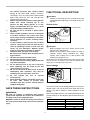
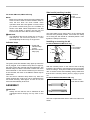
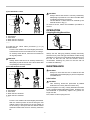
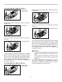
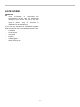
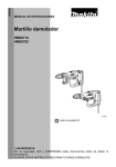
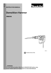
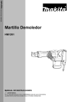
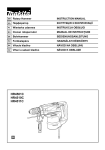
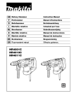
ENGLISH (Original instructions)
INSTRUCTION MANUAL
Electric Breaker
HM1317C
HM1307C
HM1317CB
HM1307CB
010282
DOUBLE INSULATION
WARNING:
For your personal safety, READ and UNDERSTAND before using.
SAVE THESE INSTRUCTIONS FOR FUTURE
REFERENCE.
1
ENGLISH
SPECIFICATIONS
Model
HM1317C
HM1307C
Blows per minute
HM1317CB
HM1307CB
730 - 1,450
Overall length
715 mm
Net weight
17.0 kg
849 mm
15.3 kg
Safety class
19.1 kg
17.5 kg
/II
• Due to our continuing programme of research and development, the specifications herein are subject to change without notice.
• Note: Specifications may differ from country to country.
• Weight according to EPTA-Procedure 01/2003
END201-4
Uncertainty (K) : 3 dB(A)
Wear ear protection
Symbols
ENG216-2
The following show the symbols used for the equipment.
Be sure that you understand their meaning before use.
・ Read instruction manual.
・
DOUBLE INSULATION
・
Only for EU countries
Do not dispose of electric equipment
together with household waste material!
In observance of European Directive
2002/96/EC on waste electric and
electronic
equipment
and
its
implementation in accordance with
national law, electric equipment that
have reached the end of their life must
be collected separately and returned to
an
environmentally
compatible
recycling facility.
Vibration
The vibration total value (tri-axial vector sum)
determined according to EN60745:
Work mode : chiseling function with side handle
Vibration emission (ah,CHeq) : 12.5 m/s2
Uncertainty (K) : 2.0 m/s2
For Model HM1307CB
ENG102-2
For European countries only
Noise
The typical A-weighted noise level determined according
to EN60745:
Sound pressure level (LpA) : 81 dB(A)
Sound power level (LWA) : 101 dB(A)
Uncertainty (K) : 3 dB(A)
Wear ear protection
ENE045-1
ENG216-2
Intended use
The tool is intended for chiselling work in concrete, brick,
stone and asphalt as well as for driving and compacting
with appropriate accessories.
Vibration
The vibration total value (tri-axial vector sum)
determined according to EN60745:
Work mode : chiseling function with side handle
Vibration emission (ah,CHeq) : 12.0 m/s2
Uncertainty (K) : 1.5 m/s2
ENF002-1
Power supply
The tool should be connected only to a power supply of
the same voltage as indicated on the nameplate, and
can only be operated on single-phase AC supply. They
are double-insulated in accordance with European
Standard and can, therefore, also be used from sockets
without earth wire.
For Model HM1317C
ENG102-2
For European countries only
Noise
The typical A-weighted noise level determined according
to EN60745:
Sound pressure level (LpA) : 81 dB(A)
Sound power level (LWA) : 101 dB(A)
Uncertainty (K) : 3 dB(A)
Wear ear protection
For Model HM1307C
ENG102-2
For European countries only
Noise
The typical A-weighted noise level determined according
to EN60745:
Sound pressure level (LpA) : 81 dB(A)
Sound power level (LWA) : 101 dB(A)
2
ENG216-2
Measured Sound Power Level: 101dB
Guaranteed Sound Power Level: 103dB
Vibration
The vibration total value (tri-axial vector sum)
determined according to EN60745:
Work mode : chiseling function with side handle
Vibration emission (ah,CHeq) : 8.5 m/s2
Uncertainty (K) : 1.5 m/s2
Model HM1307CB
Measured Sound Power Level: 101dB
Guaranteed Sound Power Level: 104dB
Model HM1317C
Measured Sound Power Level: 101dB
Guaranteed Sound Power Level: 103dB
For Model HM1317CB
ENG102-2
For European countries only
Noise
The typical A-weighted noise level determined according
to EN60745:
Sound pressure level (LpA) : 81 dB(A)
Sound power level (LWA) : 101 dB(A)
Uncertainty (K) : 3 dB(A)
Wear ear protection
Model HM1317CB
Measured Sound Power Level: 101dB
Guaranteed Sound Power Level: 104dB
8th April 2009
000230
ENG216-2
Tomoyasu Kato
Director
Makita Corporation
3-11-8, Sumiyoshi-cho,
Anjo, Aichi, JAPAN
Vibration
The vibration total value (tri-axial vector sum)
determined according to EN60745:
Work mode : chiseling function with side handle
Vibration emission (ah,CHeq) : 7.0 m/s2
Uncertainty (K) : 1.5 m/s2
GEA005-2
ENH213-1
EC Declaration of Conformity
General Power Tool Safety
Warnings
We Makita Corporation as the responsible
manufacturer declare that the following Makita
machine(s):
Designation of Machine:
Demolition Hammer
WARNING Read all safety warnings and all
instructions. Failure to follow the warnings and
instructions may result in electric shock, fire and/or
serious injury.
Model No./ Type:
HM1307C,HM1307CB,HM1317C,HM1317CB
are of series production and
Conforms to the following European Directives:
2000/14/EC, 98/37/EC until 28th December 2009
and then with 2006/42/EC from 29th December
2009
And are manufactured in accordance with the following
standards or standardised documents:
EN60745
The technical documentation is kept by our authorised
representative in Europe who is:
Makita International Europe Ltd,
Michigan, Drive, Tongwell,
Milton Keynes, MK15 8JD, England
The conformity assessment procedure required by
Directive 2000/14/EC was in Accordance with annex
VIII.
Notified Body:
TUV
Rheinland
Product
Safety
GmbH,
identification no. 0197
Model HM1307C
Save all warnings and
instructions for future reference.
The term "power tool" in the warnings refers to your
mains-operated (corded) power tool or battery-operated
(cordless) power tool.
Work area safety
1.
Keep work area clean and well lit. Cluttered or
dark areas invite accidents.
2.
Do not operate power tools in explosive
atmospheres, such as in the presence of
flammable liquids, gases or dust. Power tools
create sparks which may ignite the dust or fumes.
3.
Keep children and bystanders away while
operating a power tool. Distractions can cause
you to lose control.
Electrical safety
4.
Power tool plugs must match the outlet. Never
modify the plug in any way. Do not use any
adapter plugs with earthed (grounded) power
tools. Unmodified plugs and matching outlets will
3
Use of dust collection can reduce dust-related
hazards.
Power tool use and care
17. Do not force the power tool. Use the correct
power tool for your application. The correct
power tool will do the job better and safer at the
rate for which it was designed.
18. Do not use the power tool if the switch does
not turn it on and off. Any power tool that cannot
be controlled with the switch is dangerous and
must be repaired.
19. Disconnect the plug from the power source
and/or the battery pack from the power tool
before making any adjustments, changing
accessories, or storing power tools. Such
preventive safety measures reduce the risk of
starting the power tool accidentally.
20. Store idle power tools out of the reach of
children and do not allow persons unfamiliar
with the power tool or these instructions to
operate the power tool. Power tools are
dangerous in the hands of untrained users.
21. Maintain power tools. Check for misalignment
or binding of moving parts, breakage of parts
and any other condition that may affect the
power tool’s operation. If damaged, have the
power tool repaired before use. Many accidents
are caused by poorly maintained power tools.
22. Keep cutting tools sharp and clean. Properly
maintained cutting tools with sharp cutting edges
are less likely to bind and are easier to control.
23. Use the power tool, accessories and tool bits
etc. in accordance with these instructions,
taking into account the working conditions
and the work to be performed. Use of the power
tool for operations different from those intended
could result in a hazardous situation.
Service
24. Have your power tool serviced by a qualified
repair person using only identical replacement
parts. This will ensure that the safety of the power
tool is maintained.
25. Follow instruction for lubricating and
changing accessories.
26. Keep handles dry, clean and free from oil and
grease.
reduce risk of electric shock.
Avoid body contact with earthed or grounded
surfaces such as pipes, radiators, ranges and
refrigerators. There is an increased risk of
electric shock if your body is earthed or grounded.
6.
Do not expose power tools to rain or wet
conditions. Water entering a power tool will
increase the risk of electric shock.
7.
Do not abuse the cord. Never use the cord for
carrying, pulling or unplugging the power tool.
Keep cord away from heat, oil, sharp edges or
moving parts. Damaged or entangled cords
increase the risk of electric shock.
8.
When operating a power tool outdoors, use an
extension cord suitable for outdoor use. Use of
a cord suitable for outdoor use reduces the risk of
electric shock.
9.
If operating a power tool in a damp location is
unavoidable, use a ground fault circuit
interrupter (GFCI) protected supply. Use of an
GFCI reduces the risk of electric shock.
Personal safety
10. Stay alert, watch what you are doing and use
common sense when operating a power tool.
Do not use a power tool while you are tired or
under the influence of drugs, alcohol or
medication. A moment of inattention while
operating power tools may result in serious
personal injury.
11. Use personal protective equipment. Always
wear eye protection. Protective equipment such
as dust mask, non-skid safety shoes, hard hat, or
hearing protection used for appropriate conditions
will reduce personal injuries.
12. Prevent unintentional starting. Ensure the
switch is in the off-position before connecting
to power source and/or battery pack, picking
up or carrying the tool. Carrying power tools
with your finger on the switch or energising power
tools that have the switch on invites accidents.
13. Remove any adjusting key or wrench before
turning the power tool on. A wrench or a key left
attached to a rotating part of the power tool may
result in personal injury.
14. Do not overreach. Keep proper footing and
balance at all times. This enables better control
of the power tool in unexpected situations.
15. Dress properly. Do not wear loose clothing or
jewellery. Keep your hair, clothing, and gloves
away from moving parts. Loose clothes,
jewellery or long hair can be caught in moving
parts.
16. If devices are provided for the connection of
dust extraction and collection facilities,
ensure these are connected and properly used.
5.
GEB004-6
HAMMER SAFETY WARNINGS
1.
2.
3.
4
Wear ear protectors. Exposure to noise can
cause hearing loss.
Use auxiliary handle(s), if supplied with the
tool. Loss of control can cause personal injury.
Hold power tool by insulated gripping
surfaces, when performing an operation where
4.
5.
6.
7.
8.
9.
10.
11.
12.
13.
14.
15.
FUNCTIONAL DESCRIPTION
the cutting accessory may contact hidden
wiring or its own cord. Cutting accessory
contacting a "live" wire may make exposed metal
parts of the power tool "live" and could give the
operator an electric shock.
Wear a hard hat (safety helmet), safety glasses
and/or face shield. Ordinary eye or sun
glasses are NOT safety glasses. It is also
highly recommended that you wear a dust
mask and thickly padded gloves.
Be sure the bit is secured in place before
operation.
Under normal operation, the tool is designed
to produce vibration. The screws can come
loose easily, causing a breakdown or accident.
Check tightness of screws carefully before
operation.
In cold weather or when the tool has not been
used for a long time, let the tool warm up for a
while by operating it under no load. This will
loosen up the lubrication. Without proper
warm-up, hammering operation is difficult.
Always be sure you have a firm footing.
Be sure no one is below when using the tool in
high locations.
Hold the tool firmly with both hands.
Keep hands away from moving parts.
Do not leave the tool running. Operate the tool
only when hand-held.
Do not point the tool at any one in the area
when operating. The bit could fly out and
injure someone seriously.
Do not touch the bit or parts close to the bit
immediately after operation; they may be
extremely hot and could burn your skin.
Do not operate the tool at no-load
unnecessarily.
Some material contains chemicals which may
be toxic. Take caution to prevent dust
inhalation and skin contact. Follow material
supplier safety data.
•
CAUTION:
Always be sure that the tool is switched off and
unplugged before adjusting or checking function on
the tool.
Switch action
1. Switch lever
OFF 0
OFF
ON I
ON
1
010283
CAUTION:
Before plugging in the tool, always check to see
that the tool is switched off.
•
Switch can be locked in "ON" position for ease of
operator comfort during extended use. Apply
caution when locking tool in "ON" position and
maintain firm grasp on tool.
To start the tool, push the switch lever "ON (I)" on the left
side of the tool. To stop the tool, push the switch lever
"OFF (O)" on the right side of the tool.
•
Speed change
1. Adjusting dial
1
010284
The blows per minute can be adjusted just by turning the
adjusting dial. This can be done even while the tool is
running. The dial is marked 1 (lowest speed) to 5 (full
speed).
Refer to the table below for the relationship between the
number settings on the adjusting dial and the blows per
minute.
SAVE THESE INSTRUCTIONS.
WARNING:
DO NOT let comfort or familiarity with product
(gained from repeated use) replace strict adherence
to safety rules for the subject product.
MISUSE or failure to follow the safety rules stated in
this instruction manual may cause serious personal
injury.
Number on adjusting dial
5
4
3
2
1
010281
5
Blows per minute
1450
1350
1150
800
730
Side handle (auxiliary handle)
For model HM1317C,HM1317CB only
•
1. Set bolt
2. Nut
3. Side handle
1
NOTE:
•
Blows at no load per minute becomes smaller than
those on load in order to reduce vibration under no
load, but this does not show trouble. Once
operation starts with a bit against concrete, blows
per minute increase and get to the numbers as
shown in the table. When temperature is low and
there is less fluidity in grease, the tool may not
have this function even with the motor rotating.
2
3
010286
The side handle can be swung 360° on the vertical and
secured at any desired position. Just loosen the clamp
nut to swing the side handle to a desired position. Then
tighten the clamp nut securely.
CAUTION:
The adjusting dial can be turned only as far as 5
and back to 1. Do not force it past 5 or 1, or the
speed adjusting function may no longer work.
Installing or removing the bit
Indicator lamp
For Model HM1307C,HM1317C only
1
2
1. Power-ON
indicator lamp
(green)
2. Service indicator
lamp (red)
1. Bit
2. Tool retainer
3. Tool holder
1
2
3
010285
010287
The green power-ON indicator lamp lights up when the
tool is plugged. If the indicator lamp does not light up,
the mains cord or the controller may be malfunction. The
indicator lamp is lit but the tool does not start even if the
tool is switched on, the carbon brushes may be worn out,
or the controller, the motor or the ON/OFF switch may be
malfunction.
The red service indicator lamp flickers up when the
carbon brushes are nearly worn out to indicate that the
tool needs servicing. After approx. 8 hours of use, the
motor will automatically be shut off.
With the notched portion on the shank of the bit facing
toward the tool retainer, insert the bit into the tool holder
as far as it will go. Then pull out and turn the tool retainer
180° to secure the bit. After installing, always make sure
that the bit is securely held in place by trying to pull it
out.
For Model HM1307CB,HM1317CB only
1
1. Bit with collar
2. Bit without collar
ASSEMBLY
2
•
CAUTION:
Always be sure that the tool is switched off and
unplugged before carrying out any work on the
tool.
002928
This tool accepts bits either with or without a collar on its
shank.
6
(1) For bits with a collar
CAUTION:
Always assure that the bit is securely retained by
attempting to pull the bit out of the tool holder after
completing the above procedure.
•
The bit without a collar cannot be retained by the
method shown in Fig.(1).
To remove the bit, follow the installation procedure in
reverse.
1
•
2
3
OPERATION
5
4
Chipping/Scaling/Demolition
1. Bit
2. Tool retainer
3. Tool holder
4. When the bit is inserted
5. When the bit is retained
010293
To install the bit, follow either procedure (1) or (2)
described below.
Pivot the tool retainer back and slightly downward.
Insert the bit into the tool holder as far as it will go.
To securely retain the bit, return the tool retainer to
its original position.
010288
Always use the side grip (auxiliary handle) and firmly
hold the tool by both side grip and switch handle during
operations. Turn the tool on and apply slight pressure on
the tool so that the tool will not bounce around,
uncontrolled. Pressing very hard on the tool will not
increase the efficiency.
CAUTION:
Always assure that the bit is securely retained by
attempting to pull the bit out of the tool holder after
completing the above procedure.
(2) For bits without a collar
•
MAINTENANCE
1
•
2
CAUTION:
Always be sure that the tool is switched off and
unplugged before attempting to perform inspection
or maintenance.
Lubrication
3
CAUTION:
This servicing should be performed by Makita
Authorized or Factory Service Centers only.
This tool requires no hourly or daily lubrication because
it has a grease-packed lubrication system. However, it is
recommended to periodically replace the grease for
longer tool life.
First, switch off and unplug the tool.
•
4
5
1. Bit
2. Tool retainer
3. Tool holder
4. When the bit is inserted
5. When the bit is retained
010294
Pivot the tool retainer back and slightly downward.
With the notched portion of the bit facing the tool
retainer shaft, insert the bit into the tool holder as
far as it will go. Then pivot the tool retainer further
downward toward the barrel to securely retain the
bit.
7
For model HM1307C,HM1307CB only
Remove the six screws using a hex wrench and remove
the rear cover.
1. Rear cover
2. Hex wrench
1
1. Crank cap cover
1
2
010289
Remove the six screws using a hex wrench and remove
the rear cover.
010295
Pull out the crank cap cover in the direction of arrow and
remove it.
1. Crank cap
1
1
1. Hammer grease
010290
Pull out the crank cap in the direction of arrow and
remove it.
010296
Then replenish with fresh grease (60g). Use only Makita
genuine hammer grease (optional accessory). Filling
with more than the specified amount of grease (approx.
60 g; 2 oz) can cause faulty hammering action or tool
failure. Fill only with the specified amount of grease.
To reassemble the tool, follow the disassembling
procedure in reverse.
1. Hammer grease
1
CAUTION:
Be careful not to damage the brush holder unit and
carbon brushes especially when installing the rear
cover.
•
Do not reuse the six bolts but use new ones in the
reassembling since these bolts are applied with
adhesive.
To maintain product SAFETY and RELIABILITY, repairs,
any other maintenance or adjustment should be
performed by Makita Authorized Service Centers,
always using Makita replacement parts.
010291
•
Then replenish with fresh grease (60g). Use only Makita
genuine hammer grease (optional accessory). Filling
with more than the specified amount of grease (approx.
60 g; 2 oz) can cause faulty hammering action or tool
failure. Fill only with the specified amount of grease.
To reassemble the tool, follow the disassembling
procedure in reverse.
For model HM1317C,HM1317CB only
1. Rear cover
2. Hex wrench
1
2
010289
8
ACCESSORIES
CAUTION:
These
accessories
or
attachments
are
recommended for use with your Makita tool
specified in this manual. The use of any other
accessories or attachments might present a risk of
injury to persons. Only use accessory or
attachment for its stated purpose.
If you need any assistance for more details regarding
these accessories, ask your local Makita Service Center.
•
Bull point
•
Cold chisel
•
Scaling chisel
•
Clay spade
•
Rammer
•
Hammer grease
•
Safety goggles
•
Plastic carrying case
•
9
10
11
Makita Corporation Anjo, Aichi, Japan
884923-224
12