1
Technical Instructions
Document No. 155-517P25
Rev. 1, July, 2000
SQM5…
Reversing Actuators
ISO 9001
REGISTERED FIRM
EA0511R1
®
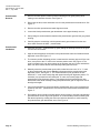
Description
SQM5... reversing actuators are used for the positioning of flow control valves, butterfly
valves, dampers, or any application requiring rotary motion. The SQM5… actuators
accommodate control input signals of 4-20 mA, 0-135 Ω, 0-10 Vdc, 0-20 mA, position
proportional and floating control. The available output signals include 4-20 mA,
0-135 Ω, 0-10 Vdc, 0-20 mA, and 0-1000 Ω. SQM5… actuators are available with up to
eight internal, easily accessible and adjustable auxiliary switches.
A selection of exchangeable circuit boards provide a variety of functions including
auto/manual selector switch, manual forward/reverse toggle switch, zero and span
adjustment, parallel or master/slave operation, split range control, input signal override,
and selectable electronic linearization.
The SQM5… is engineered for precision. It is particularly well suited to applications
requiring a high degree of modulating accuracy and repeatability. Drive shaft play is
limited to 0.3° with a modulating accuracy of 250 repositions through 90° of travel.
The SQM5… actuator may be mounted in any position. A selection of mounting
brackets and shafts provide installation flexibility and allow for the simple replacement of
most competitive actuators.
Features
•
Modulating accuracy of 250 repositions through 90°
•
Two limit switches, plus up to six internal auxiliary switches
•
Full closed “economy position” switch
•
Drive shaft and cam drum disengagement clutches
•
Auto/manual switch, manual control forward/reverse toggle switch
•
UL, CSA and CE approved 24, 110 and 220 Vac versions
•
Field reversible clockwise (cw) or counterclockwise (ccw) operation
•
Various torque ratings and running times available
•
Selection of field exchangeable one and two ended shafts
•
Mounting brackets to replace competitive actuators
Siemens Building Technologies, Inc.
Technical Instructions
Document No. 155-517P25
Rev. 1, July, 2000
Features, Continued •
Table Of Contents
Page 2
Connections for both base and face mounting
•
Low hysteresis actuator and potentiometer gearing
•
Externally visible position indication
•
Selection of input and output signals
•
Zero and span adjustment
•
Field exchangeable circuit boards and potentiometers
•
Electronic damper linearization function
•
Split range and selectable parallel or master/slave operation
• Adjustable input signal override function
Application
Product Numbers
Product numbers for pre-assembled UL/CSA/CE-approved
actuators, Table 1
Product numbers for accessories, Table 2
SQM5… Product Number Identification Legend
Installation and Operating Instructions
Shaft Installation
Rotational Direction Verification
Actuator Mounting
Switch Adjustment
Shaft Adjustment
Cam Drum Adjustment
Wiring
Electrical Connection
Grounding
Wiring Connections
AGA56.1… circuit boards
AGA56.41/42/43… circuit boards
AGA56.9… circuit boards
Commissioning
Power Actuator
Modulation Adjustment
Zero Adjustment
Span Adjustment
Position Indicating Dial Adjustment
Cover Installation
Features
SQM5x.xxxxxZx actuators
SQM5x.xxxxxGx actuators
SQM5x.xxxxxHx actuators
SQM5x.xxxxxKx actuators
SQM5x.xxxxxAx actuators
Service Guide
Reversing Rotational Direction
Shaft Installation
Circuit Board Installation
AGA56.41/42/43…
AGA56.9A
AGA56.1A97
Potentiometer Removal/Installation
Specification Data
Dimensions
Page 3
Page 3
Page 4
Page 5
Page 6
Page 7
Page 7
Page 7
Page 8
Page 8
Page 8
Page 8
Page 8
Page 9
Page 11
Page 12
Page 12
Page 12
Page 12
Page 13
Page 13
Page 14
Page 15
Page 15
Page 15
Page 16
Page 16
Page 17
Page 17
Page 18
Page 19
Page 21
Page 22
Page 23
Page 26
Siemens Building Technologies, Inc.
SQM5… Reversing Actuators
Application
Technical Instructions
155-517P25
Rev. 1, July, 2000
SQM5… actuators are uniquely suited for both industrial and commercial applications.
The high level of accuracy permits precise modulating control of industrial process and
process heating applications, often significantly enhancing performance and product
quality.
In commercial and industrial burner applications requiring high turndown and reliable
ignition, the auxiliary switches can be applied to create separate positions for burner
light off and low fire. In dual fuel applications, additional switches can be used to create
separate high fire, low fire and light off positions for each fuel. The “economy position”
switch is used to drive the actuator to the full closed position when the burner is off.
In all applications, commissioning is simplified. Shaft and switch cam drum
disengagement clutches allow for the quick manual alignment of the actuator shaft and
switch cams. The forward/reverse toggle switch in combination with the auto/manual
selector switch provides direct manual control.
Product Numbers
Table 1. Product Numbers for Pre-assembled UL/CSA/CE-Approved Actuators.
Torque
1
Running
2
Time
90°@
60 Hz
Input Control Signals
lb-in
sec
Line
Voltage
4-20
mA
90
90
90
140
140
140
140
140
140
8
8
12
25
25
25
25
25
25
X
X
X
X
X
X
X
X
X
200
200
200
25
25
25
X
X
X
310
310
37
37
X
310
400
400
37
50
50
X
X
X
X
X
X
X
0-135
Ω
Number
of
switches
3
limit/
aux.
X
X
X
X
SQM50.260R1G4
SQM50.364R1G3
SQM50.464R1A3
3
SQM50.480R1Z3
SQM50.450R1A
SQM50.460R1G3
SQM50.460R1H3
X
2/4
2/4
2/4
2/4
2/6
2/3
2/4
2/4
2/6
X
X
2/6
2/6
2/4
SQM53.480R1Z3
SQM53.480R1G3
SQM53.460R1A
2/4
2/4
SQM56.560R1A
SQM56.560R1G4
SQM56.564R1H4
3
SQM56.680R1Z3
SQM56.680R1G3
X
X
X
X
For SQM5x.xx0xxxx shafts must be ordered separately
For shaft selection refer to Table 2.
0-10
Vdc
X
X
X
Product Number
X
X
X
2/4
2/6
2/6
110 V
220 V
24 V
SQM50.260R2A
SQM50.480R2Z3
3
SQM50.480R8Z3
SQM50.450R8A
SQM50.450R8G3
SQM50.450R8H3
3
3
1. Torque will vary with the selection of the shaft. See Specifications.
2. Running time for 135° ➔ multiply by 1.5
For 50 Hz ➔ multiply by 1.2
3. SQM5x.xxxxxZx models also accept a 0-20 mA input signal.
Siemens Building Technologies, Inc.
Page 3
Technical Instructions
Document No. 155-517P25
Rev. 1, July, 2000
Table 2. Product Numbers for Accessories.
Electronic circuit boards
AGA56.1A97
AGA56.9A87
AGA56.9A17
AGA56.9A27
AGA56.41A87
AGA56.41A17
AGA56.41A27
AGA56.42A17
AGA56.42A27
AGA56.42A87
AGA56.43A17
AGA56.43A27
AGA56.43A87
24-250 Vac
24 Vac
120 Vac
220 Vac
24 Vac
110 Vac
220 Vac
110 Vac
220 Vac
24 Vac
110 Vac
220 Vac
24 Vac
Shafts
(A) board for SQM5x.xxxxxAx
(Z) board for SQM5x.xxxxxZx
(Z) board for SQM5x.xxxxxZx
(Z) board for SQM5x.xxxxxZx
(G) board for SQM5x.xxxxxGx
(G) board for SQM5x.xxxxxGx
(G) board for SQM5x.xxxxxGx
(H) board for SQM5x.xxxxxHx
(H) board for SQM5x.xxxxxHx
(H) board for SQM5x.xxxxxHx
(K) board for SQM5x.xxxxxKx
(K) board for SQM5x.xxxxxKx
(K) board for SQM5x.xxxxxKx
See Product Number Identification Legend, Figure 1.
Mounting Brackets & Adapters
AGA57.3
AGA57.4
ASK33.9
Page 4
for replacement of Honeywell MOD III, IV
actuators
for replacement of Honeywell M640/740/940 and
Barber Colman EA20/40/50/60 actuators. Directly
adaptable to Eclipse butterfly valves.
mounting kit for direct attachment to Siemens
VKF41... butterfly valve. (Shaft AGA58.1 required)
AGA58.1 10 mm round with key. Gear end only
AGA58.2 12 mm round with key. Gear end only
AGA58.3 9 mm square. Two ended
AGA58.4 3/8 inch square. Two ended
AGA58.7 14 mm round with key. Gear end only
For exact shaft sizes, refer to DIMENSIONS.
Crank Arm, Push Rods
338 031 Crank arm kit. Includes two crank arms for
connecting the AGA58.4 shaft to a ∅ 1/2-inch damper
shaft with two ball joints. (does not include push rod)
338 041
338 042
338 043
338 044
338 045
338 046
∅ 5/16" damper push rod, 12 inches long.
∅ 5/16" damper push rod, 15 inches long.
∅ 5/16" damper push rod, 18 inches long.
∅ 5/16" damper push rod, 24 inches long.
∅ 5/16" damper push rod, 36 inches long.
∅ 5/16" damper push rod, 48 inches long.
Potentiometers
ASZ12.803 1000Ω, 90°
ASZ12.833 1000Ω, 135°
ASZ22.803 1000/1000Ω double potentiometer, 90°
ASZ22.833 1000/1000Ω double potentiometer, 135°
Additional potentiometer models available. See
Siemens technical data sheet 7921.
Siemens Building Technologies, Inc.
SQM5… Reversing Actuators
Technical Instructions
155-517P25
Rev. 1, July, 2000
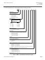
Product Number Identification Legend
For actuator identification only. To select product numbers for ordering, see Table 1.
SQM5
0
.
4
8
0
R
1
Z
3
R
Actuator family
Torque
0
0
3
6
6
in-lb @ 60 (50) Hz.
90 for 8 (10) sec. running time
140 for 12 (15), 25 (30), 37 (45) sec.
200 for 25 (30) sec.
310 for 37 (45) sec.
400 for 50 (60), 75 (90)sec.
Running time for 90°
Not all actuator running times are
available in each torque.
Refer to table 1
60 Hz.
2
8 sec.
3
12 sec.
4
25 sec.
5
37 sec.
6
50 sec.
8
75 sec.
50 Hz.
2 10 sec.
3 15 sec.
4 30 sec.
5 45 sec.
6 60 sec.
8 90 sec.
Number of SPDT switches
6 2 limit and 4 auxiliary switches
8 2 limit and 6 auxiliary switches
Shaft selection
0 no shaft (shaft must be ordered separately)
1 round 10 mm, one ended (for use with VKF41... butterfly valves)
2 round 12 mm, one ended
3 square 9 mm, two ended
4 square 3/8 inch, two ended
7 round 14 mm, one ended
Approvals
R UL recognized, CSA certified, CE approved
Operating voltage (Vac @50-60 Hz)
1 110-120 Vac
2 220-240 Vac
8 24 Vac
Internal circuit board (SQM5x.xxxxx G, H, K , Zx actuators require potentiometer ASZ…)
A AGA56.1A97 (position proportional or floating control)
G AGA56.41A... (4 to 20 mA input)
H AGA56.42A... (0 to 135 Ohm input)
K AGA56.43A... (0 to 10 Vdc input)
Z AGA56.9... (all inputs/outputs, linearization, split ranging, override and pre-set positioning)
Potentiometer (required when using SQM5x.xxxxx G, H, K, Zx actuators)
3 ASZ12.803 (1000 Ohm, 90°)
4 ASZ12.833 (1000 Ohm, 135°)
6 ASZ12.863 (1000 Ohm 160°)
7 ASZ22.803 (1000/1000 Ohm, 90°)
8 ASZ22.833 (1000/1000 Ohm, 135°)
Rotational Direction (if no R, rotation is ccw)
R Clockwise (when facing gear end. See Figure 6 .)
Figure 1. SQM5… Product Number Identification Legend.
Siemens Building Technologies, Inc.
Page 5
Technical Instructions
Document No. 155-517P25
Rev. 1, July, 2000
Installation and
Operation
Instructions
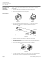
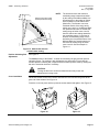
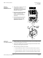
SQM5… actuators are generally shipped without the shaft installed. To install the
selected shaft:
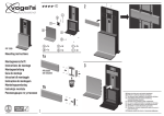
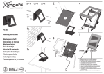
1. Loosen the two screws on the actuator cover corners. See Figure 2.
2. Lift the screws and raise the cover. See Figure 3.
EA0564R1
EA0568R1
Shaft Installation
Figure 3.
Figure 2.
3. Each shaft is supplied with two washers and a “C” clip. See Figure 4. Using
spreading pliers, remove the “C” clip and the washers from the shaft.
KEY END
INSERT END
SHAFT KEY
EA0559R1
WASHERS ON BOTH SIDES
OF THE BEARING
C-CLIP
Figure 4.
4. Insert the “insert end” of the shaft into the “gear end” of the actuator.
5. Push the shaft until the “insert end” reaches just short of the brass bushing at the
other end of the actuator.
6. Put one of the washers on the insert end of the shaft. See Figure 5.
WASHERS
EA0569R1
Figure 5.
7. Line up the “shaft key” with the key slot on the “gear end” of the actuator and slide
the shaft until the “insert end” is completely through the brass bushing.
Page 6
Siemens Building Technologies, Inc.
SQM5… Reversing Actuators
Technical Instructions
155-517P25
Rev. 1, July, 2000
8. Place the second washer onto the “insert end” of the shaft. Using spreading pliers,
install the “C” clip.
Rotational Direction
Verification
Most SQM5… actuators are factory configured for counterclockwise (ccw), minimum to
maximum rotation when facing the gear end of the actuator, or clockwise (cw) rotation
when facing the other end of the actuator. SQM5.xxxxxxxR model numbers, ending with
R are factory configured for clockwise (cw) operation. To field reverse the direction of
rotation, see Service Guide, “Reversing Rotational Direction”.
Actuator Mounting
SQM5… actuators can be mounted in any orientation using the four 1/4"-20 UNC tapped
holes located on the bottom corners of the actuator base. Optional base mounting
brackets are available. See Table 2 - Product Numbers for Accessories. SQM5…
actuators can also be face mounted using self tapping screws in combination with the
various holes on the face of the actuator gear end.
ACTUATOR
POSITION SCALE
SWITCH CAM I
SET AT MAXIMUM
SWITCH CAM II
SET AT ZERO ("ECONOMY")
ACTUATOR POSITION
INDICATING POINTER
CAM DRUM
RELEASE BUTTON
SWITCH CAM III
SET AT MINIMUM
DIAL POINTER
CAM DRUM
ASZ... (1000 Ohm)
FEEDBACK POTENTIOMETER
BOARD
50
50
50
30
30
30
30
10
10
50
0
0
0
10
0
10
0
10
70
0
ACTUATOR POSITION
INDICATING DIAL
0
SINGLE SWITCH
CAM POINTER
GEAR END
EA0561R2
DOUBLE SWITCH CAM POINTER
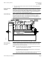
Figure 6. Component Identification on the Cam Drum Side of the SQM5… Actuator.
Switch Adjustment
See Figure 6.
All SQM5…actuators are factory wired with Switch I (maximum), Switch II (full closed
“economy position”) and Switch III (minimum). The individual switch cams I, II, and III
are factory set to 90°, 0° and 30° respectively.
NOTE:
The single switch cam pointers are used together with the black scales when
configured for counterclockwise (ccw) operation.
The double switch cam pointers are used together with the red scales when
configured for clockwise (cw) operation.
The individual switch cams can be adjusted by hand or with the use of the tool
attached to the outside of the hinged switch terminal protection lid.
Siemens Building Technologies, Inc.
Page 7
Technical Instructions
Document No. 155-517P25
Rev. 1, July, 2000
Switch Adjustment,
continued
NOTE:
Shaft Adjustment
The actuator shaft can be disengaged by pressing the silver shaft release button located
to the right of the auto/manual switch. The shaft can be manually rotated when the
button is pressed. Once pressed, the button can be locked by pushing it slightly
upwards. After the shaft has been manually aligned, re-engage the shaft by pushing the
shaft release button downwards.
See Figure 6.
Cam Drum Adjustment
See Figure 6.
SQM5x.xxxxxAx actuators may be adjusted between 0° and 160°.
SQM5x.xxxxxx3 actuators have a 90° potentiometer and the switches must be
adjusted only between 0 and 90°. SQM5x.xxxxxx4 actuators have a 135°
potentiometer and the switches must be adjusted only between 0 and 135°.
The cam drum must be manually aligned by pressing and holding the black cam drum
release button. The cam drum must be rotated until the “0” mark on the cam drum
position scale (left scale on the cam drum) is aligned with the gray actuator position
indicating pointer.
Wiring
Electrical Connection
Grounding
SQM5… actuators are equipped with two removable conduit connection plates located
on the upper corner of the gear housing. Each plate is provided with two threaded
connections for 1/2" NPSM conduit connectors. The use of flexible stranded wire is
recommended.
To avoid electro-magnetic interference, the SQM5… actuators must be grounded.
The ground terminal is located to the right of the auto/manual switch.
Wiring connections
NOTE:
SQM5… actuators require a single source, single phase power supply.
Wiring connections vary depending on which AGA56…. circuit board is installed.
AGA56.1… circuit boards.
See Figures 7 and 8.
1. Connect line voltage to terminal L. Terminal L must be powered to enable manual
operation.
2. Connect neutral to the double terminal block with the two gray motor wires, located
on the left side of the gray switch housing.
3. Connect line voltage to terminal A to drive the actuator in the opening direction.
4. Connect line voltage to terminal Z to drive the actuator in the closing direction.
Page 8
Siemens Building Technologies, Inc.
SQM5… Reversing Actuators
Technical Instructions
155-517P25
Rev. 1, July, 2000
Wiring, continued
A
L
Z
AGA56.1A97
SW1
MAN
SW 2
1
N
EA0555R2
M
I
1
11 21
I
II
III
IV...VIII
AUTO
2
II
maximum
"economy"
minimum
auxilliary
13
2
12 22
III
3
13 23
IV
4
14 24
V
5
ASZ...
15
25
Figure 7. Basic Functional Diagram of AGA56.1…
A
Z
L
MAN.
0
EA0554R2
AUTO.
AGA56.1A97
Figure 8. AGA56.1A97 Terminal/Auto-Manual Board.
AGA56.41/42/43…
circuit boards.
1. Connect line voltage to terminal L. Terminal L must be powered at all times.
2. Connect neutral to terminal N.
See Figures 9 and 10.
3. Connect ground to the terminal located to the right of the auto/manual switch.
4. For applications where terminals Z, ZL, A and 13 are not used, bridge terminal LR
and L. If any terminals Z, ZL, A or 13 are used, terminal LR must not be bridged with
terminal L. In addition, terminal LR must never be powered simultaneously with any
terminals Z, ZL, A or 13. However, terminal LR must be powered once Z, ZL, A and
13 are no longer powered and modulating operation is required (refer to application
guide for typical installation examples).
5. Connect the input control signal wires to the appropriate terminals.
Siemens Building Technologies, Inc.
Page 9
Technical Instructions
Document No. 155-517P25
Rev. 1, July, 2000
N
A
L
Z
13
LR
ZL
AGA56.4...
Y+ AGA56.41...
(4...20 mA)
Y-
U
REG
M
OPE
MAX
MAX
(+2 V)
135 Ohm
AGA56.42...
(0...135 Ohm)
Y 0...2 V
MIN
MIN
MIN
MAX
Y
Y AGA56.43...
M (0...10 V)
SW1
MIN MAX
MAN
51
SW 2
N
AUTO
1
13
3
maximum
"economy"
minimum
auxilliary
4
I
II
III
IV
11 21
12 22
13 23
14 24
M
EA0556R2
2
I
II
III
IV...VIII
V
15
5
ASZ...
(1000 Ohm)
25
Figure 9. Basic Functional Diagram of AGA56.4…
OPE MAX MIN
Y-
M Y+ Y
3
ZL
L
13
Pos
N
LR
N
A
Z
2
Z
OPE MAX MIN
L
Y
M
U
ZL
N
MAX
MAX
MIN
MIN
MAN.
Z
L
AUTO.
EA0552R2
EA0553R2
A
0
AUTO.
AGA56.41A...
Y
LR
MAN.
0
OPE MAX MIN
13
L
MM
Y
3
AGA56.42A...
L
ZL
Pos
N
L
13
N
LR
A
A
ZZ
Z
L
L
MAX
MIN
MAN.
0
EA0578R2
AUTO.
AGA56.43A...
Figure 10. AGA56.41/42/43… Terminal/Trim Potentiometer Boards.
Page 10
Siemens Building Technologies, Inc.
SQM5… Reversing Actuators
Technical Instructions
155-517P25
Rev. 1, July, 2000
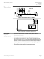
AGA56.9… circuit boards.
1. Connect line voltage to terminal L. Terminal L must be powered at all times.
See Figures 11 and 12.
2. Connect neutral to terminal N.
3. Connect ground to the terminal located to the right of the auto/manual switch.
4. For applications where terminals Z, ZL and A are not used, bridge terminals L1 and
L. If terminals Z, A or ZL are used, terminal L1 must not be bridged with terminal L.
In addition, terminal L1 must never be powered simultaneously with terminals Z, A
or ZL. However, terminal L1 must be powered once terminals A, Z and ZL are no
longer powered and modulating operation is required (refer to application guide for
typical installation examples).
5. Connect the input and output control signal wires to the appropriate terminals.
N
A
L
Z
ZL
L1
P
AGA56.9...
POS
SHIFT
LIN
MAX
ZF
75%
M
50%
POS
4...20 mA
25%
MIN
Y0...3
Y0...3
MIN 25% 50% 75% MAX
Y0...3
U4 (+2 V)
M
135 Ohm
POS
1
Y0 0...2 V
2
Y1 0...10 V
REG
OPE
MAX
MIN
MIN
MAX
MAX
J1
MIN
LIN
Y2 0...20 mA
Y3 4...20 mA
Y0...3
MIN MAX
1
SW1
2
MAN
51
SW 2
N
EA0557R2
U1..3
AUTO
1
I
J2
2
13
I
II
III
IV...VIII
3
4
II
III
IV
12 22
13 23
14 24
maximum
"economy"
minimum
auxilliary
V
15
U1
U2
U3
5
ASZ...
(1000 Ohm)
M
11 21
M
25
Figure 11. Basic Functional Diagram of AGA56.9…
Siemens Building Technologies, Inc.
Page 11
Technical Instructions
Document No. 155-517P25
Rev. 1, July, 2000
U4
M
Y0
Y1
Y2
Y3
L1
P
L
N
A
Z
ZL
OPE
MAX
MIN
MAX
POS
MIN
1
2
J2
U1...U3
1
2
J1
LIN
JUMPERS
3-POSITION
SWITCH
M
ZF
M
U1
U2
U3
MAN.
POT. METERS
0
EA0558R2
AUTO.
AGA56.9A...
Figure 12. AGA56.9… Terminal and Trim Potentiometer/ Jumper Board.
Commissioning
Power Actuator
Set the auto/manual switch in the manual position and apply power to the actuator. The
actuator can now be driven to the maximum position (switch cam I) or the full closed
“economy position” (switch cam II) by using the toggle switch located to the left of the
auto/manual switch.
Modulation Adjustment
See Figures 10 and 12.
Ensure that the OPE/MAX/MIN slide switch is set to operation (OPE). The blue MAX
trim potentiometer should be gently turned in the clockwise direction until the end stop
is reached. The blue MIN trim potentiometer should be gently turned in the
counterclockwise direction until the end stop is reached. Set the auto/manual switch in
the auto position. The actuator will now drive in response to the control input signal,
between the maximum position setting (switch cam I) and the minimum position setting
(switch cam III). If there is no control input signal, the actuator will drive to the minimum
position setting (switch cam III).
NOTE:
Switch Cam I must not be set higher than:
90° when using feedback potentiometers ASZxx..803,
135° when using feedback potentiometers ASZxx.833, or
160° when using feedback potentiometers ASZxx.863.
Zero Adjustment
See Figures 10 and 12.
Set the OPE/MAX/MIN slide switch to MIN. The blue MIN trim potentiometer can now
be gently adjusted to the required minimum position.
Span Adjustment
See Figures 10 and 12.
Set the OPE/MAX/MIN slide switch to “MAX”. The blue MAX trim potentiometer can
now be gently adjusted to the required maximum position. Return the OPE/MAX/MIN
slide switch to OPE.
Page 12
Siemens Building Technologies, Inc.
Technical Instructions
155-517P25
Rev. 1, July, 2000
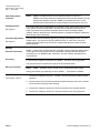
NOTE:
Example of limit switch I and III
and trim potentiometer settings
MAX tr
im pote
ntiome
ter sett
ing
Switch I setting
90 deg.
SQM5… Reversing Actuators
eter
ing
sett
iom
MIN
trim
nt
pote
Switch
ing
III sett
EA0562R1
0 deg.
The actual minimum and maximum
modulating range is determined either
by the setting of the MIN and MAX trim
potentiometers or the setting of Switch
Cam III (Minimum) and Switch Cam I
(Maximum). The actuator can never
modulate outside of the range set by
switch cam I and III. If the MIN and MAX
trim potentiometers are set outside the
setting range of switch cams I and III,
then the switch cam settings determine
the modulating range. If a soft stop is
desired, the modulating range can be
defined by the trim potentiometers if the
MIN and MAX trim potentiometers are
set inside the setting range of switch
cams I and III. See the example in
Figure 13.
Figure 13. Switch cam and trim
potentiometer setting.
Position Indicating Dial
Adjustment
See Figure 6.
The actual position of the SQM5… actuator is indicated by the gray actuator position
indicating pointer. The position is also indicated by the dial pointer. Ensure that the
actuator position indicating dial is aligned with the actuator position scale by rotating the
dial in the clockwise direction if necessary.
CAUTION:
Turning the dial in the counterclockwise direction may loosen the
potentiometer locking screw.
Cover Installation
Lift the two screws on the cover corners and slide the cover end into the groves at the
gear end of the actuator. See Figure 14.
EA0563R1
EA0567R1
Press the cover into place and then press the screws inward and tighten. See Figure 15.
Figure 14.
Siemens Building Technologies, Inc.
Figure 15.
Page 13
Technical Instructions
Document No. 155-517P25
Rev. 1, July, 2000
Features of
SQM5x.xxxxxZx
Actuators
SQM5xx.xxxxxZx actuators contain the AGA56.9A… multi function circuit board. This
circuit board provides the following features:
Multiple Input Signals
The AGA56.9A… circuit board accepts the following input signals:
Line voltage
Multiple Output Signals
•
Power to A drives the actuator open to the setting of switch cam I (Maximum).
•
Power to ZL drives the actuator closed to the setting of switch cam III
(Minimum).
•
Power to Z drives the actuator closed to the setting of switch cam II (Economy).
•
4-20 mA (Signal to Y3, common to M)
•
0-135 Ω (Slide wire signal to Y0, potentiometer connected to M and U4)
•
0-10 Vdc (Signal to Y1, common to M)
•
0-20 mA (Signal to Y2, common to M)
The AGA56.9A… circuit board provides the following output signals:
•
4-20 mA (Signal from U3, common to M)
•
0-10Vdc (Signal from U1, common to M)
•
0-20mA (Signal from U2, common to M)
Double potentiometers ASZ22… provide additional output signals.
Electronic Linearization
Function
With jumper J1 in position 1 (upper position), the linearization function is enabled. The
circuit board electronically converts the input signal to match the flow characteristics of a
typical butterfly valve. Consequently, the actuator will make smaller rotational
movements when subjected to lower input signals and larger rotational movements
when subjected to higher input signals. For example (based on a 90° modulating range),
a change in input signal from 4 to 8 mA (25% increase) will cause a rotational movement
of 11.25°. An equal signal change from 16 to 20 mA will cause a rotational movement of
45°.
With jumper J1 in position 2 (lower position), the linearization function is disabled. When
disabled, the rotational movement of the shaft is proportional to the input signal.
Input Signal Override
Line voltage to terminal P will drive the actuator to a pre-set adjustable position,
overriding all modulating input signals. Use the potentiometer marked POS to adjust the
override position to any setting within the setting range of switch cams I and III.
Parallel Operation
To configure the actuator for parallel operation, set the jumper J2 in position 1 (upper
position). Input signals Y0, Y1, Y2 or Y3 are directly shunted to output signals U1, U2
and U3. All output signals are available regardless of which input signal is applied.
Master/Slave Operation
To configure the actuator for master/slave operation, set J2 in position 2 (lower position).
The output signals U1, U2 and U3 reflect actual shaft position.
Split Ranging
AGA56.9… circuit boards have a modulating signal shift feature which can be used for
split ranging. If no signal is present on Y0, Y1, Y2 or Y3, the actuator will modulate
through the full rotational range in response to a 12 to 20 mA signal applied at ZF. If a
Page 14
Siemens Building Technologies, Inc.
SQM5… Reversing Actuators
Technical Instructions
155-517P25
Rev. 1, July, 2000
maximum signal is present on Y0, Y1, Y2, or Y3, then the actuator will modulate through
the full rotational range in response to a 4 to 12 mA signal applied at ZF. (Maximum
signal can be easily achieved by bridging terminals U4 and Y0.)
See Figure 16.
It is possible to configure the actuator for split range operation 12 to 4 mA and
20 to 12 mA. Consult your authorized Siemens Building Technologies
combustion products sales representative for details.
MAX
75%
50%
25%
EA0560R1
MIN
20
m
18 A
m
16 A
m
14 A
m
A
1
1
4
6
8
m m m 0m 2m
A A A
A A
NOTE:
MIN 25% 50% 75% MAX
Y0...3
Figure 16. Split Ranging.
Features of
SQM5x.xxxxxGx,
SQM5x.xxxxxHx,
SQM5x.xxxxxKx
Actuators
SQM5x.xxxxxGx actuators contain the AGA56.41A… circuit board with terminals Y- and
Y+ for 4-20 mA modulating input.
SQM5x.xxxxxHx actuators contain the AGA56.42A… circuit board with terminals Y, M
and U for 0-135 Ω modulating input.
SQM5x.xxxxxKx actuators contain the AGA56.43A… circuit board with terminals Y and
M for 0-10 Vdc modulating input.
Input Signals
The AGA56.4xA… circuit boards accept the following additional input signal:
Line voltage
Output Signals
•
Power to A drives the actuator open to the setting of switch cam I (Maximum).
•
Power to Z drives the actuator closed to the setting of switch cam II (Economy).
•
Power to ZL drives the actuator closed to the setting of switch cam III
(Minimum).
The AGA56.4xA… circuit boards do not provide output signals. Install a double
potentiometer ASZ22…to obtain a 0-1000 Ω actuator position output signal.
Siemens Building Technologies, Inc.
Page 15
Technical Instructions
Document No. 155-517P25
Rev. 1, July, 2000
Features of
SQM5x.xxxxxAx
Actuators
The AGA56.1A97… circuit boards accept the following additional input signal:
Input Signals
•
Power to A drives the actuator open to the setting of switch cam I (Maximum).
•
Power to Z drives the actuator closed to the setting of switch cam II (Economy).
•
Power to switch III, terminal 3 drives the actuator to the setting of switch cam III
(Minimum).
Line voltage
Output Signals
The AGA56.1A97 circuit board provides no output signals. Install a double potentiometer
ASZ22…to obtain a 0-1000 Ω actuator position output signal.
Service Guide
WARNING:
Disconnect the power supply to the actuator before performing any service
functions.
NOTE:
Reversing Rotational
Direction
Most SQM5… actuators are factory configured for counterclockwise (ccw),
minimum to maximum rotation when facing the gear end of the actuator or
clockwise (cw) rotation when facing the other end of the actuator.
1. Disconnect the double blue wires marked 21 and the double black wires marked 12
from switch I, terminal 21 and switch II, terminal 12 respectively.
2. Connect the double blue wires marked 21 to switch II, terminal 12. Connect the
double black wires marked 12 to switch I, terminal 21.
3. See Figure 6. Adjust all switch cams to the desired settings using the red cam drum
scales in combination with the double switch cam pointers.
NOTE:
Press and hold the black cam drum release button to rotate the cam drum.
This will give easy access to the switch cams and a better view of the cam
drum scales.
4. If no potentiometer ASZ… is installed, the reversing procedure is complete. If a
potentiometer ASZ… is installed, complete Steps 5 through 11.
GEAR WITH MARK "0"
FOR CLOCKWISE
ROTATION
GEAR WITH MARK "1" FOR
COUNTERCLOCKWISE ROTATION
BOARD
ALIGNMENT
SCREW
BOARD
ALIGNMENT
SCREW
1
0
TERMINAL
BLOCK
POTENTIOMETER GEAR
ALIGNMENT POINTER
TERMINAL
BLOCK
POTENTIOMETER GEAR
ALIGNMENT POINTER
EA0518R1
EA0517R1
E
POTENTIOMETER
POTENTIOMETER GEAR
ATTACHMENT SCREW
E
BLU
CK
BLA
WN
WN
BRO
BRO
CK
BLU
BL A
POTENTIOMETER GEAR
ATTACHMENT SCREW
POTENTIOMETER
Figure 17. Reversing Rotational Direction on the ASZ Potentiometer Board.
5. See Figure 17. Disconnect the blue and brown wires from the terminal block located
on the ASZ… potentiometer circuit board.
Page 16
Siemens Building Technologies, Inc.
SQM5… Reversing Actuators
Technical Instructions
155-517P25
Rev. 1, July, 2000
6. Reconnect the brown wire to the left terminal and the blue wire to the right terminal.
The black wire remains connected to the middle terminal.
7. See Figure 6. Remove the white plastic actuator position-indicating dial by gently
pulling while rotating in the clockwise direction.
8. The actuator position indicating pointer, located near the actuator gear end of the
cam drum, must point to the “0” mark on the actuator position scale (scale on the
cam drum nearest to the actuator gear end). Press and hold the black cam drum
release button while manually rotating the cam drum.
9. See Figure 17. Loosen the black potentiometer gear attachment screw
approximately one turn. Gently wedge a small screwdriver between the
potentiometer gear and the gray plastic housing. Gently twist the screwdriver until
the potentiometer gear releases from the cam drum shaft.
10. Manually rotate the potentiometer gear in the counterclockwise direction until the
white line next to the “0” mark on the potentiometer gear face is exactly in
alignment with the potentiometer gear alignment pointer. Firmly tighten the black
potentiometer gear attachment screw while manually holding the potentiometer gear
in alignment. Check the alignment again.
11. Re-install the white actuator-indicating dial by gently pressing it onto the
potentiometer gear attachment screw. Align scale position “0” on the actuator
position indicating dial with the dial pointer by rotating the dial in the clockwise
direction to avoid loosening the potentiometer gear attachment screw.
Shaft Installation
See Installation and Operation Instructions.
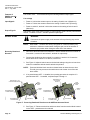
Preparation before
Circuit Board Installation
WARNING:
Disconnect the power supply to the actuator before replacing the
circuit boards.
The actuator motor capacitor is attached to
the lower section of the gray plastic switch
housing using snap-on holding clips.
Gently pull the capacitor forward until it
unclips and temporarily place it on top of
the gear housing. See Figure 18.
EA0570R1
The black circuit board mounting bracket,
installed on the inside base of the SQM5…
actuator has four vertical, slotted circuit
board supports. Remove the terminal
section and circuit board(s) from the
mounting bracket.
CAPACITOR
Figure 18.
CAUTION:
Do not disconnect any capacitor wiring.
Siemens Building Technologies, Inc.
Page 17
Technical Instructions
Document No. 155-517P25
Rev. 1, July, 2000
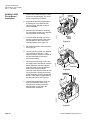
AGA56.41/42/43
Circuit Board
Installation
1. Remove the AGA56.41/42/43… circuit
board from the packaging. The circuit
board is shipped as one board.
TERMINAL
SECTION
2. Separate the board at the perforation
by holding the circuit board at both
ends and gently bending the board
until it separates.
4. From the switch housing side of the
actuator, guide the base circuit board
into the bottom of the circuit board
mounting bracket. See Figure 19.
EA0574R1
3. Move the terminal section containing
the auto/manual switch to the opposite
end of the base circuit board.
BASE
CIRCUIT
BOARD
Figure 19.
5. Re-install the actuator motor capacitor.
See Figure 20.
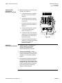
7. Gently guide the terminal section into
the support slots and slide the terminal
board downward until both supports
snap into place. Ensure that the four
brown wires and the flat white
connector cable which connect the two
circuit boards are positioned correctly
in their respective corners allowing the
board to freely slide into place without
pinching either wire. See Figure 21.
EA0575R1
6. Connect the blue neutral wire, shipped
loose with the AGA56.9A…, to the
spade connector marked N located on
the terminal board just below the
auto/manual switch
CAPACITOR
Figure 20.
TERMINAL
SECTION
EA0576R1
8. Connect the bundled blue, black and
brown potentiometer wires to the
terminal block located on the ASZ…
potentiometer circuit board. See
Potentiometer Installation.
Figure 21.
Page 18
Siemens Building Technologies, Inc.
SQM5… Reversing Actuators
AGA56.41/42/43
Circuit Board
Installation, continued
Technical Instructions
155-517P25
Rev. 1, July, 2000
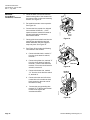
9. Make the following connections to the
actuator: See Figure 22.
a. Connect the black wire, marked “1”
from the circuit board to switch I,
terminal 1.
18
28
8
17
27
7
16
26
6
15
25
5
14
24
4
13
23
3
12
22
2
11
21
1
VIII
VII
VI
V
IV
III
II
I
13
b. Connect the yellow wire, marked
“2” from the circuit board to switch
II, terminal 2.
c.
Connect the white wire, marked “3”
from the circuit board to switch III,
terminal 3.
3
2
N
d. Connect the brown wire, marked
“13” from the circuit board to
switch III, terminal 13.
f.
MAN.
0
AUTO
EA0577R2
e. Connect the other end of the blue
neutral wire to the double terminal
block located on the outer end of
the switch housing
TERMINAL 1
BLOCK
N
51
Figure 22.
Connect the gray grounding wire
marked "51" to the ground terminal
located to the right of the
auto/manual switch.
AGA56.9A…
1. Remove the ASZ... potentiometer if
Circuit Board Installation
already installed on the SQM5...
actuator. See Potentiometer
Removal/Installation Instructions.
2. Remove the AGA56.9A… circuit
boards from the packaging. The three
separate AGA56.9A circuit boards are
shipped in a circuit board mounting
bracket.
3. Remove the two upright circuit boards
from the mounting bracket by gently
pulling aside the vertical supports and
sliding the boards upward. Remove the
base circuit board from the bottom of
the mounting bracket. Discard the
shipping mounting bracket.
Siemens Building Technologies, Inc.
Page 19
Technical Instructions
Document No. 155-517P25
Rev. 1, July, 2000
AGA56.9A…
Circuit Board
Installation, continued
4. Guide the base circuit board from the
switch housing side of the actuator into
the bottom of the circuit board mounting
bracket. See Figure 23.
5. Re-install the actuator motor capacitor.
See Figure 24.
EA0571R1
6. Connect the blue neutral wire, shipped
loose with the AGA56.9A…, to the
spade connector marked N located on
the terminal board just below the
auto/manual switch.
BASE
CIRCUIT
BOARD
Figure 23.
7. Gently guide the terminal board into the
support slots and slide the terminal
board downward until both supports
snap into place. See Figure 25.
8. See Figure 26 and make the following
connections to the actuator:
b. Connect the yellow wire, marked “2”
from the circuit board to switch II,
terminal 2. Connect the white wire,
marked “3” from the circuit board to
switch III, terminal 3.
c.
EA0572R1
a. Connect the black wire, marked “1”
from the circuit board to switch I,
terminal 1.
CAPACITOR
Figure 24.
Connect the brown wire, marked
“13” from the circuit board to switch
III, terminal 13.
TERMINAL
SECTION
e.
Connect the gray grounding wire
marked "51" to the ground terminal
located to the right of the
auto/manual switch.
EA0573R1
d. Connect the other end of the blue
neutral wire to the double terminal
block located on the outer end of
the switch housing.
Figure 25
Page 20
Siemens Building Technologies, Inc.
SQM5… Reversing Actuators
AGA56.9A…
Circuit Board
Installation, continued
Technical Instructions
155-517P25
Rev. 1, July, 2000
9. Gently guide the L-shaped circuit board
containing the three blue trim
potentiometers into the vertical support
slots located on the cam drum side of
the actuator. See Figure 27.
18
28
8
17
27
7
16
26
6
15
25
5
14
24
4
13
23
3
12
22
2
11
21
1
VIII
VII
VI
V
IV
III
II
I
13
10. Slide the circuit board downward until
both supports snap into place. Install
the ASZ… potentiometer (See
Potentiometer Removal/Installation
Instructions).
3
2
N
11. Connect the bundled blue, black and
brown potentiometer wires to the
terminal block located on the ASZ…
potentiometer circuit board.
1
MAN.
0
EA0565R2
AUTO
N
51
Figure 26.
EA0566R1
L-SHAPED
CIRCUIT
BOARD
Figure 27.
AGA56.1A97
1. Install the AGA56.1A97 circuit board into the two slotted circuit board supports located
Circuit Board Installation
on the switch housing side of the actuator.
2. Gently guide the AGA56.1A97 circuit board into the support slots and slide the board
downward until both supports snap into place.
3. Make the following connections to the actuator:
a. Connect the black wire, marked “1” from the circuit board to switch I, terminal 1.
b. Connect the yellow wire, marked “2” from the circuit board to switch II, terminal 2.
c.
Siemens Building Technologies, Inc.
Connect the brown wire, marked “13” from the circuit board to switch III, terminal
13.
Page 21
Technical Instructions
Document No. 155-517P25
Rev. 1, July, 2000
Potentiometer
Removal
1. Remove the white plastic actuator position-indicating dial by gently pulling while
rotating in the clockwise direction. See Figure 6.
2. Disconnect the blue, black and brown wire from the potentiometer terminal block. See
Figure 17.
3. Remove the silver potentiometer board alignment screw.
4. Loosen the black potentiometer gear attachment screw approximately one turn.
5. Gently wedge a small screwdriver between the potentiometer gear and the gray plastic
housing.
6. Carefully twist the screwdriver until the potentiometer gear releases from the cam
drum shaft. Remove the ASZ… potentiometer.
Potentiometer
Installation
1. Install the new ASZ… potentiometer by gently sliding the bushing inserted in the gear
over the cam drum shaft.
2. Align the board alignment screw hole in the potentiometer board and install the board
alignment screw. See Figure 17.
3. The actuator position indicating pointer, located near the actuator gear end of the cam
drum, must point to the “0” mark on the actuator position scale. See Figure 6. The
scale is located on the cam drum nearest to the actuator gear end. Press and hold the
black cam drum release button while manually rotating the cam drum.
4. Manually rotate the potentiometer gear until the white line next to the “0” or “1” mark
on the potentiometer gear face is exactly in alignment with the potentiometer gear
alignment pointer. See Figure 17. For counterclockwise (ccw) operation the line
beside the “1” mark must exactly align with potentiometer gear alignment pointer. For
clockwise (cw) operation the line beside the “0” mark must exactly align with
potentiometer gear alignment pointer. Firmly tighten the black potentiometer gear
attachment screw while manually holding the potentiometer gear in alignment. Check
the alignment again.
5. Connect the bundled blue, black and brown potentiometer wires to the terminal block
located on the ASZ… potentiometer circuit board. See Potentiometer Installation and
Figure 17.
6. Re-install the white actuator-indicating dial by gently pressing it onto the potentiometer
gear attachment screw. Align scale position “0” on the actuator position indicating dial
with the dial pointer by rotating the dial in the clockwise direction to avoid loosening
the potentiometer gear attachment screw. See Figure 6.
Page 22
Siemens Building Technologies, Inc.
SQM5… Reversing Actuators
Specifications
SQM5... Reversing
actuator
Technical Instructions
155-517P25
Rev. 1, July, 2000
SQM5... Reversing actuator
Agency approvals
Operating voltage
Operating frequency
Power consumption
Type of motor
Duty cycle
Torque
Maximum shaft torque
AGA58.1
AGA58.2
AGA58.3
AGA58.4
AGA58.7
Timings
Rotational range of operation
SQM5x.xxxxxA models
SQM5x.xxxxxx3 models
SQM5x.xxxxxx4 models
SQMSx.xxxxxx6 models
Direction of rotation
Shaft
Shaft disengagement
Number of auxiliary switches
Limit switches
Electrical rating of auxiliary switches
Mounting position
Ambient operating temperature
Shipping temperature
NEMA ratings
Connections
Switches
Boards
Dimensions
Weight
Housing
Enclosure (cover)
Motor
Disengagements
Siemens Building Technologies, Inc.
UL, CSA, CE
24 Vac +10%-15%
110 Vac-15% to 120 Vac +10%
220 Vac-15% to 240 Vac +10%
50-60 Hz
20 VA
Reversing synchronous motor
100%
See Table 1.
90 lb-in
200 lb-in
220 lb-in
270 lb-in
350 lb-in
See Table 1.
0-160°
0-90°
0-135°
0-160°
Reversible, factory setting: ccw
Selectable. See Table 2.
Custom versions on request
Independent, cam and drive shaft
6 switches (maximum)
2 switches (standard)
7.5 (3) A, 250 Vac
Optional
-5 to 140°F (-20 to 60°C)
-58 to 140°F (-50 to 60°C)
NEMA 1, 2, 3, 3R, 3S, 5, 12, and 13
Spade connectors
Screwed and spade connectors
See Figures 28 through 31.
7.3 lbs. (3.3 kg)
Aluminum pressure die casting
Lexan
Lock resistant
Manual for drive and cam shaft
Page 23
Technical Instructions
Document No. 155-517P25
Rev. 1, July, 2000
Conduit connection
Gears and bearings
Mounting
Adaptation to other actuator brands
Circuit Boards
AGA56.1A97
AGA56.41A…
AGA56.1A97 Switch circuit board
Operating voltage
Operating frequency
Auto/manual switch
Manual toggle switch
Ambient operating temperature
Shipping temperature
Weight
AGA56.41A… Electronic circuit boards
Operating voltage
Operating frequency
Ambient operating temperature
Shipping temperature
Input signal
Impedance
AGA56.42A…
Current input
Zero adjustment
Span adjustment
Auto/manual switch
Manual toggle switch
Weight
AGA56.42A… Electronic circuit boards
Input signal
Impedance
Page 24
Two removable inserts with two
1/2-inch NPSM threads.
Each insert allows insertion of entire
cable tree for easy servicing
Maintenance free
Four 1/4"-20 UNC screws in bottom
Face mounting at gear side also
possible
Screw pattern and shaft height
Adaptation with AGA57... adapters
See Table 2.
Voltage independent
50-60 Hz
2-position switch
3-position switch
-5 to 140°F (-20 to 60°C)
-58 to 140°F (-50 to 60°C)
0.22 lb. (0.1 kg)
Single potentiometer
ASZ... (1000 ohm) is required
24 Vac +10%-15%
110 Vac -15% to 120 Vac +10%
220 Vac -15% to 240 Vac +10%
50-60 Hz
-5 to 140°F (-20 to 60°C)
-58 to 140°F (-50 to 60°C)
4-20 mA
≤300 Ω
MIN: 0-75 %
MAX: min-100 %
2-position switch
3-position switch
0.7 lb. (0.33 kg)
Same specifications as AGA56.41A
except
0-135 Ohm
Current input
≤300 Ω
Voltage input
≥100kΩ
Siemens Building Technologies, Inc.
SQM5… Reversing Actuators
Technical Instructions
155-517P25
Rev. 1, July, 2000
Specifications,
continued
AGA56.43A…
AGA56.43A… Electronic circuit boards
Input signal
Impedance
AGA56.9A
Voltage input
AGA56.9A… Multi function electronic
circuit boards
Operating voltage
Operating frequency
Input signals
Same specifications as AGA56.41A
except:
0-10 Vdc
≥100kΩ
Single potentiometer
ASZ... (1000 ohm) is required
24 Vac +10%-15%
110 Vac -15% to 120 Vac +10%
220 Vac -15% to 240 Vac +10%
50-60 Hz
4-20 mA,
0-20 mA,
0-10 Vdc,
0-135 ohm
Impedance
Current input
Voltage input
Output signals
Zero adjustment
Span adjustment
Split ranging (SHIFT)
Input signal override (POS)
ASZ... Potentiometers
Ambient operating temperature
Shipping temperature
Auto/manual switch
Manual toggle switch
Weight
ASZ... Potentiometers
Versions
Resistor values
Hysteresis
Siemens Building Technologies, Inc.
≤300 Ω
≥100kΩ
4-20 mA
0-20 mA,
0-10Vdc
MIN: 0-75 %
MAX: min-100 %
4-20 mA on terminal ZF
Line voltage (... Vac) on terminal P
adjust with POS potentiometer
-5 to 140°F (-20 to 60°C)
-58 to 140°F (-50 to 60°C)
2-position switch
3-position switch
0.7 lb. (0.33 kg)
Single and double potentiometer
See Table 2 and data sheet 7921.
< 0.3 % related to drive shaft
Page 25
Technical Instructions
Document No. 155-517P25
Rev. 1, July, 2000
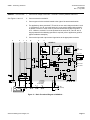
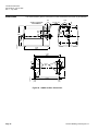
Dimensions
The first dimension given is measured in inches. Millimeters are shown in parentheses.
ALLOW 3.5" SPACE FOR
COVER REMOVAL
5/8
(16)
1-3/16
(30)
Pg 13.5 / 1/2"
NPSM
1/4
(6)
M8
1-3/16
(30)
5-1/4
(133)
1-7/16
(36)
3/8
(10)
EA0522R1
2-5/8
(67)
7-1/16
(180)
7-1/16
(180)
1/16
(1)
4-7/16
(113)
1/4"-20
UNC
1/8
(3.5)
3 -1/8
(80)
EA0542R2
5-3/16
(132)
5/16
(8.5)
6-7/16
(164)
5/16
(7.5)
Figure 28. SQM5x.xxxRxx Dimensions.
Page 26
Siemens Building Technologies, Inc.
SQM5… Reversing Actuators
Technical Instructions
155-517P25
Rev. 1, July, 2000
6-7/16
(164)
11/16
(18)
9/16
(14.5)
4-1/16
(103.3)
4-7/8
(123.8)
AGA57.3
EA0519R1
4-7/16
(113)
4 X 1/4
(7)
4 X 1/4
(7)
1/8
(3)
2-1/8
(80)
CL
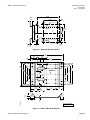
Figure 29. Mounting Bracket AGA57.3
7-5/16
(185)
1-9/16
(40)
2-1/4
(57.15)
7/16
(11)
6-7/16
(164)
5/16
(7.94)
5-5/16
(135)
4-3/4
(120.65)
4-7/16
(113)
3-1/8
(80)
5/16
(7.94)
5/16
(8.73)
1-3/8
(35)
2-3/8
(60.4)
4-7/16
(113)
4
(101.5)
AGA57.4
CL
3-1/8
(80)
5/16
(8.73)
2-1/2
(63.5)
5/16
(7.94)
2-3/8
(60.64)
1-5/8
(42)
2
(50.8)
1-11/16
(43)
1-1/2
(38.1)
45
45
1/2
(12.5)
EA0520R2
13/16
(20.3)
1/8
(3)
13/16
(20.3)
All non-sized holes
O 5/16 (7.62)
Figure 30. AGA57.4 Mounting Bracket.
Siemens Building Technologies, Inc.
Page 27
Technical Instructions
Document No. 155-517P25
Rev. 1, July, 2000
7.09
(180)
0.31
(8)
GEAR SIDE
1
(25.5)
0.39
(10)
0.79
(20)
0.35
(9)
AGA58.1
0.12
(3)
0.44
(11.2)
1
(25.5)
0.47
(12)
0.79
(20)
0.35
(9)
AGA58.2
0.81
(20.5)
0.35
(9)
0.12
(3)
0.52
(13.2)
0.85
(21.5)
0.35
(9)
0.43
(11)
0.35
(9)
AGA58.3
M5 x 9
M5 x 9
0.67
(17)
0.78
(19.8)
0.42
(10.6)
0.375
(9.5)
0.27
(6.9)
8-32 UNC
28 x 0.56
(14.2)
0.42
(10.6)
AGA58.4
0.05
(1.3)
0.375
(9.5)
0.27
(6.9)
8-32 UNC
28 x 0.56
(14.2)
0.05
(1.3)
0.55
(14)
1.71
(43.5)
1.10
(28)
0.20
(5)
0.60
(15.1)
EA0543R1
AGA58.7
0.20
(5)
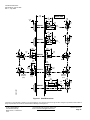
Figure 31. Shaft Dimensions.
Information in this publication is based on current specifications. The company reserves the right to make changes in specifications and models as
design improvements are introduced. © 2000 Siemens Building Technologies, Inc.
Siemens Building Technologies, Inc.
Landis & Staefa Division
1000 Deerfield Parkway
Buffalo Grove, IL 60089-4513
U.S.A.
Your feedback is important to us. If you have
comments about this document, please send
them to technical.editor@sbt.siemens.com
Document No. 155-517P25
Printed in the U.S.A.
Page 28