1
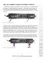
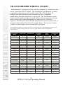
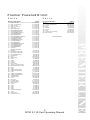
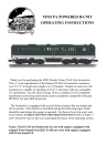
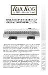
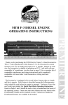
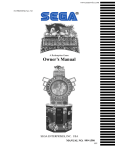
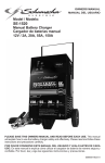
ELECTRIC
TRAINS
R
MTH F-3 POWERED B-UNIT
OPERATING INSTRUCTIONS
Thank you for purchasing the MTH Electric Trains F-3 B-Unit
locomotive. This ¼” scale reproduction of the famous F-3 B-Unit
locomotive measures over 13 1/2” in length and weighs over 3.5 pounds.
Despite its scale size, the locomotive is capable of operating on O-31 3-rail
track with any compatible AC transformer (see the chart on page 8 for a
complete list of compatible transformers and wiring instructions) and is
completely compatible with past MTH F-3 AA and ABA diesel sets.
The locomotive is equipped with several deluxe features that are simple
and fun to operate. Each feature is described among the following pages
which should be read before the engine is operated. For those of you who
can’t wait to get started, the Quick Start Basic Operating Instructions
found on Pages 3 and 4 should be read so that you understand the basics of
the operating system.
Table Of Contents
QUICK START - BASIC OPERATION
DCRU® Reverse Unit Operation
3
3
USING YOUR POWERED F-3 B UNIT WITH PFA/FYS
EQUIPPED F-3 AA OR ABA
4
OIL & LUBRICATION INSTRUCTIONS
5
TRACTION TIRE REPLACEMENT INSTRUCTIONS
6
O-31 OPERATION
7
TRANSFORMER WIRING CHART
8
PARTS LIST
9
EXPLODED VIEW
10
SERVICE AND WARRANTY INFORMATION
11
HOW TO GET SERVICE
11
LIMITED ONE YEAR WARRANTY
11
2
MTH F-3 B-Unit Operating Manual
QUICK START - BASIC OPERATION
The MTH F-3 B Unit contains state-of-the art electronics with several
built-in automatic features for incredibly realistic operation. The F-3
B-Unit is easy to operate with your existing MTH F-3 AA or ABA units
using any compatible standard AC transformer (see the compatibility chart
on page 8). The F-3 powered B-Unit is controlled by a DCRU® electronic
reverse unit which unit operates in the same manner that all reverse units
function by using forward, neutral and reverse states that are entered each
time the throttle is turned on and off or by using the transformer direction
switch (if so equipped). Simply plug the B-Unit wire harness into the
existing sockets of the F-3 AA or ABA set to allow Proto-Coupler®
equipped engines and directional lighting systems to function. Once
connected, advance the transformer throttle to cycle all AA and B units
together from RESET to Forward as explained in the DCRU section below.
DCRU® REVERSE UNIT
As mentioned in the Basic Operating section, the engine is controlled by a
DCRU® reverse unit that contains the standard forward-neutral-reverse
states found on most reverse units. However, when power is first applied to
the track, the reverse unit begins in RESET or what seems like a neutral
state. Power must be interrupted again to get the locomotive to enter the
forward state. The system will enter RESET whenever power to the track is
off for three or more seconds. NEUTRAL should be referred to as the state
between Forward and Reverse.
Because the ProtoSound® system or DCRU® reverse unit found in your
powered MTH F-3 A unit is not directly connected to the DCRU® unit in
your powered F-3 B-Unit, you
must cycle the power on and off
Neutral
slowly to maintain proper
synchronization between each
RESET
Forward
Reverse
powered unit’s reverse unit. If
Neutral
the units should become
unsynchronized, simply shut
Figure 2: DCRU™ Cycle Phases
down power for three or more
seconds. Upon repowering, each
unit should come up in RESET. If you choose to operate your existing F-3
A units in a “locked-out” state, a lockout switch on the powered F-3 B-Unit
has been provided so that you can manually “lock-out” the B-Unit in the
same direction the powered A Units are configured.
3
MTH F-3 B-Unit Operating Manual
USING THE POWERED F-3 B-UNIT WITH
PFA/FYS EQUIPPED MTH F3 AA OR ABA
You can utilize the PFA/FYS that came equip on previous MTH Premier F3
AA or ABA by reading the following instructions. Refer to your Premier F3
AA or ABA for operation instruction of PFA/FYS. Your MTH Premier
Powered F3 B-unit has a DCRU installed in it, which is not directly connected
to the ProtoSound of your powered A unit. Because the Powered B-unit is not
directly connected to the ProtoSound, the Powered B-unit will cycle its
directional states while the ProtoSound A unit is playing the PFA/FYS events.
To operate the Powered F-3 B-unit with your ProtoSound A unit, the only
thing to remember is not to set the voltage on the transformer too high, not
above 8-10 volts. If the voltage is set to high, the Powered B-unit will begin
vibrating on the track, as its motors will be turning. Since the directional
cycles of the DCRU are insink with the number of events played during the
PFA/FYS, the Powered B-unit will start in the same direction as the
ProtoSound A unit after the PFA/FYS has finished playing.
4
MTH F-3 B-Unit Operating Manual
OIL & LUBRICATION INSTRUCTIONS
In order for the engine to perform correctly and quietly, it is important that
the chassis be lubricated before operation. Lubrication should include all
truck block bushings and pickup rollers to prevent them from squeaking.
Use light household oil and follow the lubrication points marked “L" in Fig.
3 below.
L
L
Figure 3: Lubricating The Chassis
The locomotive’s internal gearing in both power trucks has been greased at
the factory and shouldn’t need additional grease until after 50 hours of
operation or one year whichever comes first. Grease cannot be added to the
internal gearing until the body is removed from the chassis which is held in
place by four Phillips screws. The screws are located on each end of the
chassis as seen in Fig. 5 on the following page. After removing the screws,
lift the body away from the chassis and lay the body next to the chassis.
Next, remove the truck blocks from the chassis by unscrewing the large
Phillips motor mount screw on the bottom of each truck block (See Fig. 5).
Once the motor mount screw has been removed, pull the motor away from
GREASE
Figure 4: Greasing The Chassis Trucks
5
MTH F-3 B-Unit Operating Manual
the truck block and lightly coat the motor worm gear and bronze drive gear
(in the truck block) with grease. Reassemble the truck and motor, being
careful not to pinch the pickup and ground wires between the truck block
and motor mount. Repeat the procedure for the other motor and truck and
then reassemble the chassis to the body. When reassembling the chassis and
body, be very careful that the lighting wire harnesses are not caught
between the body and chassis as this can lead to a short which may damage
the electronic circuit boards beyond repair.
In addition to the truck block internal gearing, it is a good idea to lubricate
the outside truck block “idler" and “drive" gears with grease. Use the
diagram shown in Fig. 4 above as a guide and add grease to the points
marked with a “G".
Periodically, check the locomotive wheels and pickups for dirt buildup as
this can significantly affect the engine’s ability to perform properly. Dirty
track and dirty wheels can cause both poor electrical contact as well as poor
traction, especially on elevated track sections. Finally, dirt and oil build up
can prematurely wear out the neoprene traction tires.
TRACTION TIRE REPLACEMENT
INSTRUCTIONS
Your locomotive is equipped with two neoprene rubber traction tires on
each power truck. While these tires are extremely durable and long-lasting
there may arise a time where they will need to be replaced. Should this
occur, you will need to remove the truck sides from the truck block from the
chassis in order to slip the new tire over the grooved drive wheel. The truck
Body Mount Screws
Motor Mount Screw
Figure 5: Removing The body From The Cahssis
6
MTH F-3 B-Unit Operating Manual
Body Mount Screws
sides can be removed from the truck block by turning the engine upside
down and unscrewing the two phillips head screws.
Before the new tire can be installed, you must make sure the old tire has
been completely removed from the groove in the drive wheel. Use a razor
blade or small flatblade screwdriver pry away any remains left from the old
tire that may still be in the drive wheel groove. Once the old tire has been
completely removed, slip the new tire onto the wheel. You may find it
useful to use two small flatblade screwdrivers to assist you in stretching the
tire over the wheel. Be careful to avoid twisting the tire when stretching it
over the wheel. If a twist occurs, the tire will have to be removed and
reinstalled or a noticeable wobble in your engine will occur when operating
the locomotive. In addition, it is important to make sure that the tire is
fully seated inside the groove. Any portion of the tire extending out of the
groove can cause the engine to wobble. A razor blade can be used to trim
away any excess tire that doesn’t’t seat itself inside the groove properly.
Once the new tire(s) are in place, reassemble the truck sides to the truck
blocks and then reassemble the chassis to the body. Replacement tires are
available directly from MTH Electric Trains.
O-31 OPERATION
While the MTH F-3 B-Unit is more than capable of operating on O-31
curves and switches, you may find that certain light freight cars are prone to
derailing when being pulled or pushed by the MTH F-3 through O-31
switches. Should this occur, we suggest adding weight to the cars making
them heavier and less likely to derail.
7
MTH F-3 B-Unit Operating Manual
TRANSFORMER WIRING CHART
ProtoSounds® is designed to work with any standard AC transformer that
uses a “Pure Sine-Wave" format. The chart below lists the many Lionel®
compatible transformers, such as the Lionel KW or ZW models. In
addition, the chart details how the terminals on these compatible
transformers should be attached to your layout. The Trainmaster system
from Lionel® (marked with an asterisk below) will not function correctly
with ProtoSounds without disrupting the sound effects. Therefore,
whenever ProtoSounds senses that the Trainmaster system is being used, it
automatically disables ProtoSound’s sound effects. The operator retains
control over the engine, but no sound effects will play.
*ProtoSounds needs over 14 volts of power to work properly. Overloading or using in-line
accessories with this transformer may lower the peak voltage below ProtoSound’s
requirements.
Transformer
Model
Center Rail
Outside Rail
Min/Max.
Voltage
Power
Rating
Transformer
Type
Lionel 1032
U
A
5-16v*
90-Watt
Standard
Lionel 1032M
U
A
5-16v*
90-Watt
Standard
Lionel 1033
U
A
5-16v*
90-Watt
Standard
Lionel 1043
U
A
5-16v*
90-Watt
Standard
Lionel 1043M
U
A
5-16v*
90-Watt
Standard
Lionel 1044
U
A
5-16v*
90-Watt
Standard
Lionel 1053
U
A
8-17v
60-Watt
Standard
Lionel 1063
U
A
8-17v
60-Watt
Standard
All-Trol
Left Terminal
Right Terminal
0-24v
300-Watt
Electronic
0-18v
135V.A.
Electronic
Standard
Cab-1/Powerma
st er
A
U
Dallee Hostler
Left Terminal
Right Terminal
Lionel LW
A
U
8-18v
75-Watt
Lionel KW
A or B
U
6-20v
190-Watt
Standard
MRC Tech II
Left Terminal
2 nd From Left
0-15v*
40V.A.
Electronic
Lionel MW (not
recommende d)
Outside Track
Terminal
Inside Track
Terminal
5-16v*
50V.A.
Electronic
R.O.W.
Red Terminal
Black Terminal
0-24v
384-Watt
Standard
Lionel RS-1
Red Terminal
Black Terminal
0-18v
50V.A.
Electronic
Lionel RW
U
A
9-19v
110-Watt
Standard
Lionel SW
U
A
Unknown
130-Watt
Standard
Lionel TW
U
A
8-18v
175-Watt
Standard
Lionel ZW
A or D
U
8-20v
275-Watt
Standard
MTH Z4000
Red
Black
5-21v
390-Watt
Electronic
8
MTH F-3 B-Unit Operating Manual
Premier Powered B Unit
P a r t s
Name and Number
1.)
1.)
1.)
1.)
1.)
1.)
2.)
2.)
2.)
2.)
2.)
2.)
3.)
3.)
3.)
3.)
3.)
3.)
4.)
4.)
4.)
4.)
5.)
6.)
7.)
8.)
9.)
10.)
11.)
12.)
13.)
14.)
15.)
16.)
17.)
18.)
19.)
20.)
21.)
21.)
22.)
23.)
23.)
24.)
24.)
25.)
26.)
27.)
27.)
28.)
29.)
30.)
31.)
32.)
33.)
34.)
35.)
36.)
37.)
Shell ( AT & SF )
Shell ( C& O #8506 )
Shell ( B & M )
Shell ( L & N #701 )
Shell ( RI )
Shell ( ARR #1503 )
Vent (right)(AT&SF)(silver)
Vent (right)(C&O)(blue)
Vent (right)(B&M)(maroon)
Vent (right)(L&N)(blue)
Vent (right)(RI)(black)
Vent (right)(ARR)(blue/yellow)
Vent (left)(AT&SF)(silver)
Vent (left)(C&O)(blue)
Vent (lef t)(B&M)(maroon)
Vent (left)(L&N)(blue)
Vent (left)(RI)(black)
Vent (left)(ARR)(blue/yellow)
Vent (top)(AT&SF)(silver)
Vent (top)(L&N)(blue)
Vent (top)(ARR)(blue)
Vent (top)
(RI,B&M,C&O)(black)
Diaphram
Handrail (18.5mm long)
Handrail (31.5mm long)
Lens (portal)(11.0mm)
Rubber band
Motor
DCRU board
Screw
Screw
Bracket
Chassis
Motor mount
Spacer (2.0X4.5X14.5mm)
PCB board (w/wire harness)
Screw
Screw
Ladder (chassis)( silver )
Ladder (chassis)( black )
Screw
Ladder (truckside)(silver)
Ladder (truckside)(black)
Truckside (silver )
Truckside (black )
Screw
Wire strap
Fuel tank (s ilver)
Fuel tank (black)
Switch (small)
Screw
Screw
Screw
Screw
Screw
Insulator (top)(square)
Screw
Traction tires
Truck block (2axle)
P a r t s
Part #
FC-2100094
FC-2100095
FC-2100096
FC-2100097
FC-2100098
FC-2100099
FC-2110012
FC-2110013
FC-2110014
FC-2110015
FC-2110016
FC-2110017
FC-2120012
FC-2120013
FC-2120014
FC-2120015
FC-2120016
FC-2120017
FC-2100100
FC-2100101
FC-2100102
FC-2100103
Name and Number
38.)
39.)
40.)
41.)
42.)
43.)
44.)
45.)
46.)
Nut
Insulator (bottom)(rect.)
Pick-up
E-clip
Washer
Spring
T-bar
Coupler (non-operating)
Wire harness
* Requires Exchange
FI-0000017
FC-2100104
FC-2100105
FA-0000001
BI-4500004
BE-0000022
AC-0000001
IA-0000055
IA-0000094
IH-0000039
DH-2100006
BI-0000009
ID-0000050
BB-0000014
IA-0000095
IA-0000044
FC-2100106
FC-2100107
IA-0000037
FC-2100108
FC-2100109
DB-2100005
DB-2100006
IA-0000003
IH-0000012
FC-2100110
FC-2100111
BB-0000009
IA-0000076
IA-0000001
IA-0000012
IA-0000041
IA-0000015
BD-0000015
IA-0000016
DE-0000018
DA-2000002
9
MTH F-3 B-Unit Operating Manual
Part #
IC-0000005
BD-0000039
BD-0000025
IF-0000002
ID-0000026
IE-0000007
IG-0000001
DD-4000005
BC-0000011
10
MTH F-3 B-Unit Operating Manual
WARNING:
When using electrical products, basic safety precautions should be followed including the
following:
-- Read this and all related manuals (transformer/power supply, locomotive, etc.) thoroughly
before using this device.
-- This device is not recommended for children under eight years of age without adult
supervision.
-- MTH recommends parents examine the toy transformer used to power this device
periodically for conditions that may result in the risk of fire, electric shock, or injury to
persons, such as damage to the primary or output cord, plug blades, housing or other parts
(including proper functioning of the circuit breaker), and that, in an event such conditions
exist, the transformer should not be used until properly repaired.
SERVICE & WARRANTY INFORMATION
HOW TO GET SERVICE UNDER THE TERMS OF THE
LIMITED ONE YEAR WARRANTY
For warranty repair, do not return your product to the place of purchase unless it was
purchased from Mike’s Train House in Columbia, MD. Instead, follow the instructions below
to obtain warranty service as our dealer network is not prepared to service the product under
the terms of this warranty.
1. First, write, call or FAX MTH Electric Trains, 7020 Columbia Gateway Drive, Columbia,
MD 21046, 410-381-2580 (FAX No. 410-381-6122), stating when it was purchased and what
seems to be the problem. You will be given a return authorization number to assure that your
merchandise will be properly handled upon its receipt.
2. CAUTION: Make sure the product is packed in its original factory packaging including its
foam and plastic wrapping material so as to prevent damage to the merchandise. The shipment
m ust be prepaid and we recommend that it be insured. A cover letter, including your name,
address, daytime phone number, Return Authorization number, a copy of your sales receipt
and a full description of the problem, must be included to facilitate the repairs. Please
include the description regardless of whether you discussed the problem with one of our
service technicians when contacting MTH for your Return Authorization number.
3. Please make sure you have followed the instructions carefully before returning any
merchandise for service.
LIMITED ONE YEAR WARRANTY
This item is warranted for one year from the date of purchase against defects in material or
workmanship. We will repair or replace (at our option) the defective part without charge for
parts or labor, if the item is returned to the address below within one year of the original date
of purchase. This warranty does not cover items that have been abused or damaged by careless
handling. Transportation costs incurred by the customer are not covered under this warranty.
This warranty gives you specific legal rights and you may have other rights which vary from
state to state.
11
MTH F-3 B-Unit Operating Manual