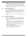
1
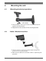
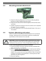
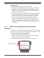
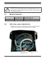
EX80/EX82-IP Infrared
Imager
EX80/EX82-IP
en
Installation Manual
EX80/82-IP
| en
1
Important safety instructions
Type numbers: NEI-808V04-11, NEI-809V04-11, NEI-808V04-21, NEI-809V04-21
NEI-828V04-11, NEI-829V04-11, NEI-828V04-21, NEI-829V04-21, NEI-828V09-11
NEI-829V09-11 | NEI-828V09-21 | NEI-829V09-21
Read, follow, and retain all of the following safety instructions. Heed all warnings on
the unit and in the operating instructions.
1.
Cleaning - Unpower the unit before cleaning. Follow any instructions provided
with the unit. Generally, using a dry cloth for cleaning is sufficient, but a moist
fluff-free cloth or leather shammy may also be used. Do not use liquid
cleaners or aerosol cleaners.
2.
Heat Sources - Do not install the unit near any heat sources such as radiators,
heaters, stoves, or other equipment (including amplifiers) that produce heat.
3.
Object and liquid entry - Never push objects of any kind into this unit through
openings as they may touch dangerous voltage points or short-out parts that
could result in a fire or electrical shock. Never spill liquid of any kind on the
unit. Do not place objects filled with liquids, such as vases or cups, on the unit.
4.
Controls adjustment - Adjust only those controls specified in the operating instructions. Improper adjustment of other controls may cause damage to the
unit. Use of controls or adjustments, or performance of procedures other than
those specified, may result in hazardous radiation exposure.
5.
Overloading - Do not overload outlets and extension cords. This can cause
fire or electrical shock.
6.
Power sources - Operate the unit only from the type of power source indicated
on the label. Before proceeding, be sure to disconnect the power from the cable to be installed into the unit.
- For external power supplied units, use only the recommended or approved
power supplies.
- For limited power source units, this power source must comply with
EN60950. Substitutions may damage the unit or cause fire or shock.
- For 24 VAC units, voltage applied to the unit's power input should not
exceed 24 VAC. User-supplied wiring must comply with local electrical
codes (Class 2 power levels). Do not ground the supply at the terminals or
at the unit's power supply terminals.
- If unsure of the type of power supply to use, contact your dealer or local
power company.
7.
Damage requiring service - Unplug the unit from the main AC power source
and refer servicing to qualified service personnel when any damage to the
equipment has occurred, such as:
- the power supply cord or plug is damaged;
- liquid has been spilled in or on the equipment;
Bosch Security Systems
Quick Install
MAN80/82IPB Rev.0 | 2008.10
2
en |
8.
9.
10.
EX80/82-IP
- an object has fallen into the unit;
- unit has been dropped or the unit cabinet is damaged;
- unit exhibits a distinct change in performance;
- unit does not operate normally when the user correctly follows the
operating instructions.
Safety check - Safety checks should be performed upon completion of service
or repairs to the unit to ensure proper operating condition.
Installation - Install in accordance with the manufacturer's instructions and in
accordance with applicable local codes.
Attachments, changes, or modifications - Only use attachments/accessories
specified by the manufacturer. Any change or modification of the equipment,
not expressly approved by Bosch, could void the warranty or, in the case of
an authorization agreement, authority to operate the equipment.
i
o
!
!
i
DANGER! High risk: This symbol indicates an imminently hazardous
situation such as " Dangerous Voltage " inside the product. If not
avoided, this will result in an electrical shock, serious bodily injury, or
death.
CAUTION! Alerts the user to the risk of damage to the unit
WARNING! Medium risk: Indicates a potentially hazardous situation.
If not avoided, this may result in minor or moderate injury. Alerts the
user to important instructions accompanying the unit.
NOTE! This symbol indicates information or a company policy that
relates directly or indirectly to the safety of personnel or protection of
property.
o
MAN80/82IPB Rev.0 | 2008.10
Quick Install
Bosch Security Systems
EX80/82-IP
| en
3
The full version Installation Manual is available on the enclosed CD-ROM and can
be viewed and printed out with Acrobat Reader, which is also on the enclosed
CD-ROM. This user guide is the intellectual property of BOSCH Security Systems
and is protected by copyright
CAUTION!
–
Camera Grounding - For mounting the camera in potentially
damp environments, ensure to ground the system using the
ground connection of the power supply connector (see section:
Connecting external power supply).
–
U.S.A. models only - Section 810 of the National Electrical
Code, ANSI/NFPA No.70, provides information regarding proper
!
grounding of the mount and supporting structure, grounding of
the coax to a discharge unit, size of grounding conductors, location of discharge unit, connection to grounding electrodes, and
requirements for the grounding electrode.
–
Permanently connected equipment - Incorporate a readily
accessible disconnect device in the building installation wiring.
–
Power lines - Do not locate the camera near overhead power
lines, power circuits, or electrical lights, nor where it may contact
such power lines, circuits, or lights.
Bosch Security Systems
Quick Install
MAN80/82IPB Rev.0 | 2008.10
4
en |
1.1
EX80/82-IP
Unpacking
Parts list (items supplied with unit)
- EX80/82IP Infrared Imager™ Assembly
- Installation Instructions booklet
- Allen Key
- EXMB028B or EXMB028W cable management mounting bracket
- Extra window (wide illumination beam) for 4-9mm version only
- Software CD
Items required for installation
(not supplied with units)
- Mounting hardware
- Mounting tools
- PC/Laptop with RJ45 Ethernet port
- Power supply
1.2
Initial Preparations
1.) Determine the operating voltage at the installation site. The
camera‘s Voltage Regulator Board accepts 12-24VAC / VDC input
without change to internal connections.
2.) Determine the optimum mounting location for the camera. See
Section 2, Camera Mounting.
3.) All cameras have been tested and pre-focused with telephoto
setting as factory default prior to shipment. If any adjustment
needed, it is advisable to check the camera’s operation before
installation
4.) Install IP Camera Software on PC.
MAN80/82IPB Rev.0 | 2008.10
Quick Install
Bosch Security Systems
EX80/82-IP
2.
2.1
| en
5
Mounting the unit
Mounting bracket preparation
SET SCREW
1.) Use the supplied Allen Key to remove the setscrew from the
supplied mounting bracket.
2.) Separate the two sections of the mounting bracket.
2.2
Cable / Bracket insertion
1.) Carefully feed the Power and Ethernet cables through both
sections of the mounting bracket.
2.) Make sure the cables are not kinked, chafed, or split during this
procedure.
Bosch Security Systems
Quick Install
MAN80/82IPB Rev.0 | 2008.10
6
en |
2.3
EX80/82-IP
Mounting bracket attachment
1.) Attach the Mounting Bracket to the Camera’s Mounting Block
using the six bolts supplied with the bracket
2.) Snug the two halves of the bracket together with the Allen head
set screw
3.) Tighten the setscrew enough so that the camera can be adjusted
for angle. Do not over-tighten.
4.) Note the angled part of the mounting bracket faces to the rear of
the camera
2.4
Camera: Mounting and setup:
Select a suitable location that protects the camera from accidental
damage, tampering and environmental conditions exceeding the
specifications of the camera to be mounted.
!
CAUTION! Ensure the selected location is protected from falling
objects, accidental contact with moving objects and unintentional
interference from personnel. Follow all applicable building codes.
These mounting guidelines should be followed:
1.) Locate the bracket such that it cannot be easily interfered with,
either intentionally or accidentally.
2.) Select a smooth, flat mounting surface to ensure proper sealing.
The surface must also be capable of supporting the combined
weight of the camera and mounting hardware under all expected
conditions of vibration and temperature. Camera performs best
mounted 3-6m off the ground.
3.) Secure all cabling.
MAN80/82IPB Rev.0 | 2008.10
Quick Install
Bosch Security Systems
EX80/82-IP
| en
7
Camera Setup:
To determine if the camera is receiving a picture:
1.) Make sure the supplied software is installed in your PC/laptop
computer (For Camera Configuration and Software Viewing
Setup, refer to full version Installation Manual available on the
enclosed CD-ROM -Section 4).
2.) Connect the camera to the PC/laptop and power up the camera.
Follow the prompts. See section 2 of full version Installation
Manual available on the enclosed CD-ROM for more detail.
3.) Launch Configuration Manager or web-browser. Refer to
Configuration Manager User Manual for information. Refer to
section 4 of full version Installation Manual available on the
enclosed CD-ROM for more detail on camera configuration via
web browser.
2. 5
Camera lens adjustments and window
selection
For optimum picture quality, the camera lens should be as close as
possible to the inside face of the viewing window, without touching.
For focus adjustment follow the steps below.
1.) Loosen the four bolts from the extrusion
2.) Remove the faceplate, window and the lens foam, set aside.
Make sure the photocell is not dislodged.
3.) Perform the proper lens adjustments as per section 2.6
Loosen four bolts
Bosch Security Systems
Quick Install
MAN80/82IPB Rev.0 | 2008.10
8
en |
2.6.
EX80/82-IP
Vari-focal and “auto iris” control adjustment
Note: Use Infra-Red Pass filter to cover the lens during focusing to
simulate low light conditions on scene for correct 24-hour focusing.
For camera with manual iris lens, the camera should be focused with
i
the lens iris fully opened to simulate the worst possible depth of field.
Using a Infra-Red Pass filter will ensure the iris is fully open for correct setup and adjustment.
Note that statement above is applicable only for Day/Night or IR
version cameras.
Set screws
photocell
Photocell
1.) Loosen the lens set screws for focus/zoom adjustments
2.) The setscrew marked N ←→ ∞ is used for image focus
3.) The setscrew marked T←→ W is used for telephoto or
wide-angle settings.
4.) Re-tighten the setscrews after focus adjustments have been
completed.
MAN80/82IPB Rev.0 | 2008.10
Quick Install
Bosch Security Systems
EX80/82-IP
!
2.7
| en
CAUTION! The CCD image sensors are highly sensitive and require
special care for proper performance and extended lifetime. Do not
expose them to direct sunlight or bright spot lights in operating and
non-operating conditions.
Window Selection
Narrow Window
Wide Window
2.8
9
Recommended
focal length [mm]
18-50mm
5-18mm
Recommended HFOV @ 100ft /
30m distance [ft / m]
28ft / 8m and narrower
Wider than 18ft / 8m
LED array- power adjustments
If adjustment is needed, the following procedure must be followed:
1) Remove the rear cover of the camera. Set cover aside.
Photocell
Adjustment Pot
Bosch Security Systems
Quick Install
IR Adjustment
Pot
MAN80/82IPB Rev.0 | 2008.10
10 en |
EX80/82-IP
The EX80/82IP needs to be powered-up while making the LED power
adjustments. Cover the photocell to turn the LEDs “ON” (850nm
LEDs will have a slight red glow). Adjust the LED power if they are
too bright or too dim. For IR power adjustment, rotate VR1. Clockwise
is high and counter-clockwise is low
2.9
Photocell Adjustment
The photocell is factory set optimum level. In some conditions such
as with bright foreground objects the camera may switch too early or
too late. For photocell “On/Off” light-level adjustment, rotate IR
Adjustment Pot. Clockwise is off and counter-clockwise is on.
Re-assemble the IP board into the chassis and carefully attach the
rear cover.
2.10
Camera re-assembly
Make sure all wires are properly connected, all holes are sealed
against moisture penetration, and all mounting screws are tight.
1.) Position the photocell properly in the small hole of the window
foam.
2.) Slide the lens foam over the camera lens. Make sure the foam is
snug and as close to the faceplate viewing window as possible
and the photocell is secure with an unobstructed view.
3.) Attach the window, faceplate, and the rear cover to the camera
housing. Tighten the four bolts.
4.) Tighten the camera’s adjustable mounting bracket after the
desired viewing angle has been determined.
5.) Power-up the camera and check its operation.
MAN80/82IPB Rev.0 | 2008.10
Quick Install
Bosch Security Systems
Americas
Bosch Security Systems, Inc.
850 Greenfield Road
Lancaster, Pennsylvania 17601
USA
Telephone +1 888-289-0096
Fax
+1 585-223-9180
Email: security.sales@us.bosch.com
www.boschsecurity.us
Europe, Middle East, Africa:
Bosch Security Systems B.V.
P.O. Box 80002
5600 JB Eindhoven, The
Netherlands
Phone: + 31 40 2577 284
Fax: +31 40 2577 330
emea.securitysystems@bosch.com
www.boschsecurity.com
Asia-Pacific:
Bosch Security Systems Pte Ltd
38C Jalan Pemimpin
Singapore 577180
Phone: +65 6319 3450
Fax: +65 6319 3499
apr.securitysystems@bosch.com
www.boschsecurity.com
© Bosch Security Systems, Inc. 2009; Data subject to change without notice.