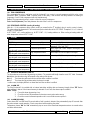
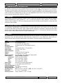
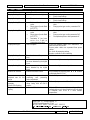
1
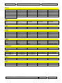
Instructions Manual
cod. 1592001121
81,9(56$/²59
NEW FEATURES on the V3.0
•
HEATING :
As well as cooling, the Universal-R can now be used to control heating applications up to
+105c, using the NTC probes supplied in box.
For temperatures above 105c and up to maximum +150c, please order special PTC
probe (S6.SH), Part No. DIXL957
•
AUTOMATIC PROBE REGOGNITION:The Universal-R can work with either NTC or PTC probes.
It can now automatically recognise which type of probe is connected and set itself
accordingly.
During auto probe recognition, probe temperature must be Min. –50c, Max. + 60c
•
PROBES SUPPLIED AS STANDARD:
The Universal-R is now supplied with 2 of the latest fully encapsulated NTC probes
•
HOT KEY PROGRAMMING:You can now use a “Hot Key” (Part No. DIXL695) to transfer parameter settings between
one Universal-R and another (V3.0 only)
•
DIGITAL INPUT:
The Universal-R now has a digital input that you can configure to accept external signals,
i.e. - door switch, pressure switch, alarms, energy saving etc.
(9(1 025( )/(;,%,/,7< 025( &219(1,(1&( 7+(
81,9(56$/5
&$1 12: 5(3/$&( :(// 29(5 27+(5 &21752//(56 1.
Instructions Manual
cod. 1592001121
INDEX
1. INDEX_________________________________________________________________________________2
2. GENERAL WARNING ____________________________________________________________________3
3. GENERAL DESCRIPTION _________________________________________________________________3
4. QUICK START UP PROCEDURE – Up and running in 6 easy steps_________________________________4
TYPICAL CONNECTIONS - FOR GENERAL GUIDANCE ONLY _______________________________________5
6. PARAMETER TABLE and factory default settings _______________________________________________6
7. SERVICE REPLACEMENT - MODELS AND PROBE INFORMATION _______________________________7
8. PARAMETERS – THEIR FUNCTIONS IN DETAIL_______________________________________________9
9. BUTTONS – WHAT ARE THEIR FUNCTIONS ________________________________________________11
10. PROGRAMMING MODE _________________________________________________________________11
11. OTHER FEATURES OF THE UNIVERSAL-R _________________________________________________12
12. THERMOSTAT OVERRIDE ( not available when parameter “tC” = 1 or 6 ) ___________________________12
13. DEFROST TYPES ______________________________________________________________________12
14. EVAPORATOR FAN CONTROL ( only when parameter “tC” = 5 )__________________________________12
15. SPECIAL APPLICATIONS – TWIN COMPRESSOR – DEAD BAND CONTROL_______________________13
16. ALARMS______________________________________________________________________________13
17. REMOVING SECURITY CODE PROTECTION ________________________________________________14
18. MOUNTING ___________________________________________________________________________14
19. ELECTRICAL CONNECTIONS ____________________________________________________________14
20. PROBES______________________________________________________________________________14
21. TECHNICAL DATA______________________________________________________________________14
22. FAULT FINDING_______________________________________________________________________15
1592001121 Universal-R3 GB 19.11.2004.doc
rel. 1.0
Pa. 2 / 15
Instructions Manual
cod. 1592001121
2. GENERAL WARNING
WARNING: The Universal-R should always be installed by a suitabley qualified person, in accordance with best
electrical and refrigeration practice. Take time to read the instructions. Do not exceed the relay ratings. The
Universal-R should not be considered a safety device, use suitable safety cutout devices when appropriate.
•
•
•
This manual is part of the product and should be kept near the instrument for easy and quick reference.
The instrument shall not be used for purposes different from those described hereunder. It cannot be used as a
safety device.
Check the application limits before proceeding.
2.1 SAFETY PRECAUTIONS
•
•
•
•
•
•
•
•
•
•
Check the supply voltage is correct before connecting the instrument.
Do not expose to water or moisture: use the controller only within the operating limits avoiding sudden temperature
changes with high atmospheric humidity to prevent formation of condensation
Warning : Disconnect all electrical connections before any kind of maintenance.
The instrument must not be opened.
Fit the probe where it is not accessible by the End User.
In case of failure or faulty operation send the instrument back to the distributor with a detailed description of the
fault.
Do not exceed the maximum current that can be applied to each relay (see Technical Data).
Ensure that the wires for probes, electrical loads and the power supply are separated and far enough from each
other, without crossing or intertwining.
In case of applications in industrial environments, the use of mains filters (our mod. DIXL930) in parallel with
inductive loads could be useful.
Heating applications – Do not exceed 105c with the NTC probes supplied. For higher temperatures (up to a
maximum of 150c) use special PTC probes - our Part No. DIXL957.
3. GENERAL DESCRIPTION
Model Universal-R is a 32x74 mm format microprocessor based controller suitable for applications on high, medium or
low temperature refrigeration units. It is provided with three relay outputs to control compressor, defrost - which can be
either electrical or hot gas - and evaporator fans. It can work with PTC or NTC probes. Where defrost is being
terminated by time, it can operate with just one thermostat probe or where defrost is being terminated by temperature, it
has an input for a second (evaporator) probe.
The Universal-R is equipped with an internal alarm buzzer, a flashing visual alarm as well as a 4th relay ( volt free ) that
can be configured as Auxiliary, Alarm or to control a heater in Dead Band control (see parameter oAc)
Each instrument is fully configurable through special parameters that can be easily programmed through the keypad.
1592001121 Universal-R3 GB 19.11.2004.doc
rel. 1.0
Pa. 3 / 15
4.
Instructions Manual
cod. 1592001121
QUICK START UP PROCEDURE – Up and running in 6 easy steps
This Quick Start Up section is designed to get you up and running with the minimum of fuss. Just follow these 6 simple
steps.
STEP 1 - Using the table below, decide which type of controller you wish the Universal-R to
function as and take note of the required setting for parameter “tC”
Also take note of the number of probes to be connected.
Type of Control
Number
Paramete
of probes
r “tC”
required
setting
1
x1
On / Off thermostat – Cooling
2
x1
Off cycle defrost (timed)
3
x1
Electrical / Hot Gas defrost, time initiated / time terminated
4
x2
Electrical / Hot Gas defrost, time initiated / temperature terminated
5
x2
Electrical / Hot Gas defrost, time initiated / temperature terminated + evap. fan delay
6
x1
On / Off thermostat – Heating
Note: “tC” settings 3, 4 & 5, default to Electrical Defrost. Hot Gas is possible by setting parameter “tdF” for gas defrost.
Settings 1,2,3 & 6 do not require the 2nd probe to be fitted
Ð
STEP 2 - Install the new Universal-R and connect up the wiring and probe(s).
If in doubt, refer to Section on typical wiring connections
Ð
STEP 3 - Turn on the power supply to the controller
For 1 minute, you now have direct access (without pass code) to parameter “tC” and to start the automatic probe type
recognition, after which these parameter settings will have to be done manually and the pass code will have to be
entered.
Ð
STEP 4 - Within 1 minute from the power on, press the n button for 3 seconds, the
controller will automatically recognise if the probes connected to it are PTC or NTC. During
recognition time the controller will display: tPd (type of probe detection) followed by the
kind of probe “ntc” or “Ptc” flashing for few seconds.
Notes: Probe temperature must be between –50c & + 60c for automatic probe recognition to work correctly
When using 2 x probes, both must be the same type, you cannot mix them.
Ð
STEP 5 – Within 1 minute from the power on, press the “SET + n ” buttons for 3 seconds
and the label “Pr2” will be shown, release the buttons and parameter “tC” will be
displayed, then press the “SET” button again to see the current setting and adjust using the
o & n buttons to the setting you require for your particular application.
Allow display to return to normal
Ð
STEP 6 - Press the “SET” button for 3 seconds until the small LED’s at the top of the
display start to flash and the Set Point value is displayed, then adjust the “Set Point” using
the o & n buttons.
IMPORTANT: Finally turn off the power then turn back on again
Ð
We recommend you you check the parameter default settings listed in these instructions to ensure they suit your
particular application. If you need to make further parameter adjustments or you require more information, read the
following sections
1592001121 Universal-R3 GB 19.11.2004.doc
rel. 1.0
Pa. 4 / 15
5.
Instructions Manual
cod. 1592001121
TYPICAL CONNECTIONS - FOR GENERAL GUIDANCE ONLY
Parameter tC = 1, 2 or 6
Parameter tC = 3
On / Off thermostat or Off Cycle Defrost
Controller
Forced defrost controller, time initiated & time
terminated
Line
8(3)A250V
Max
10A
8(3)A
a
8(3)A
8(3)A
a
8(3)A
8(3)A250V
Max
10A
8(3)A
R oo m
R oo m
probe
Line
Not used
Alarm/ Line N.C .
Compr.
AUX
or liquid
Not used
line valve
(or Heater when tC=6)
N.C .
Alarm/ Line N.C .
AUX
Comp
Def
8(3)A
Not used
Parameter tC = 5
Forced defrost controller, time initiated &
temperature terminated with evaporator fan
delay after defrost
Comp
Alarm/ Line N.C .
AUX
8(3)A250V
Max
10A
a
R oo m
8(3)A
Def
N.C .
8(3)A
8(3)A
Line
E va p.
8(3)A
a
8(3)A
8(3)A250V
Max
10A
R oo m
E va p.
Parameter tC = 4
Forced defrost controller, time initiated &
temperature terminated
Line
N.C .
Def
Fan Comp
8(3)A
Alarm/ Line N.C .
AUX
Not used
1592001121 Universal-R3 GB 19.11.2004.doc
rel. 1.0
Pa. 5 / 15
Instructions Manual
cod. 1592001120
6. PARAMETER TABLE and factory default settings
IMPORTANT : Always set parameter “tC” first. As you move “tC” between settings 1 to 5, all non- relevant parameters
will become masked out. Once “tC” has been set correctly, you can then alter any other parameter if you need to.
WARNING!!
Always switch the power OFF then ON at the end of programming to initiate changes.
If parameter “tC” is set to 4 or 5 without an evaporator probe fitted, a P2 probe alarm will be generated. If you
do intend to use settings 4 or 5 fit a probe, if you intend to use settings 1, 2 or 3, you must switch the power
OFF then ON again to clear the alarm.
UNIVERSAL R
Type (category) of controller
Label
tC
Adjustment Range
1 = On / Off Thermostat
Factory defaults with parameter “tC” 1- 6
1
2 = Off cycle defrost
2
3 = Time / time defrost
3
4 = Time / temp defrost
4
5 = Time / temp defrost + fan delay
5
6 = On / Off Thermostat for heating
Probe type
PbC
Differential
6
1
1
1
1
1
1
HY
0 = PTC
1 = NTC
0.2 ÷ 30.0 °c
2.0
2.0
2.0
2.0
2.0
2.0
Minimum Set Point limit
LS
- 50 °c ÷ Set Point
-50.0
-50.0
-50.0
-50.0
-50.0
-50.0
Maximum Set Point limit
US
Set Point ÷ 150 °c
50.0
50.0
50.0
50.0
50.0
50.0
Anti-short cycle delay
AC
0 ÷ 30 mins.
1
1
1
1
1
1
Temperature alarm configuration
ALC
1
1
1
1
1
High temperature alarm
ALU
50
50
50
50
50
Low temperature alarm
ALL
- 50
- 50
- 50
- 50
- 50
Temperature alarm delay
Delay of temperature alarm at start up
Outputs activation delay at start up
Thermostat override
Defrost delay after thermostat override
Interval between defrosts
Delay start of defrost
( Maximum ) duration of defrost
Defrost termination temperature
Display during defrost
ALd
dAO
OdS
CCT
dAF
IdF
dSd
MdF
dtE
dFd
15
90
0
15
90
0
0
2
4
0
15
15
90
0
0
2
6
0
15
15
90
0
0
2
6
0
30
8.0
15
90
0
0
2
6
0
30
8.0
3
3
3
3
10
10
10
10
0
0
0
0
0
2
1
1
1
Defrost display time out
dAd
Defrost type ( forced )
tdF
Drain down time
Fdt
First defrost after power on
dPO
Evaporator fan operating mode
FnC
Evaporator fan stop temperature
Evaporator fan delay after defrost
FSt
Fnd
0 = Relative to SP
1 = Absolute
0 ÷ 50 °c (Relative)
ALL÷150 °c (Absolute)
0 ÷ 50 °c (Relative)
- 50 °c ÷ ALU (Absolute)
0 ÷ 250 mins.
0 ÷ 720 mins.
0 ÷ 250 mins.
0 ÷ 990 mins.
0 ÷ 250 mins.
1 ÷ 250 hours
0 ÷ 59 mins.
0 ÷ 250 mins.
- 50 ÷ 150 °c
0 = Real temp.
1 = Temp. at defrost start
2 = Set Point
3 = “DEF” label
4 = “DEG” label
0 ÷ 250 mins.
0 = Electrical
1 = Hot Gas
0 ÷ 60 mins.
0 = Immediate
1 = After normal interval
0÷4
( 1 = Fan always on apart from
during defrost. See section 10 for
info. on other settings )
- 50 ÷ 150 °c
0 ÷ 250 mins.
1592001121 Universal-R3 GB 19.11.2004.doc
1
1
25
7
rel. 1.0
Pa. 6 / 15
1
50
- 50
15
90
0
Instructions Manual
UNIVERSAL R
Thermostat probe calibration
Evaporator probe calibration
Display Resolution
Label
Adjustment Range
Ot
OE
rES
0.0
0.0
0.0
0.0
0.0
0.0
0.0
0
0
0
0
0
0
0
0
0
0
15
15
15
15
15
15
30
30
30
30
30
30
1
1
1
1
1
1
5
5
5
5
5
5
0
0
0
0
0
0
0
0
0
0
0
0
0
0
0
0
0
0
0
0
0
0
0
0
Compressor ON time with faulty probe
COn
- 12.0 ÷ 12.0 °c
- 12.0 ÷ 12.0 °c
0 = With decimal point
1 = No decimal point
0 = ° Celsius
1 = ° Fahrenheit
0 ÷ 250 mins.
Compressor OFF time with faulty probe
COF
0 ÷ 250 mins.
tbA
Temperature measurement unit (°C/°F)
cod. 1592001120
CF
Factory defaults with parameter “tC” 1- 6
0.0
0
0
Digital input polarity
diP
0 = Mute buzzer only
1 = Mute buzzer & relay
0=Start defrost: 1=Door switch
2=Auxiliary relay: 3=Energy saving
4=Remote On/OFF:
5=Generic alarm: 6=Serious alarm
0=Closed circuit: 1=Open circuit
Digital input delay
did
0-255 minutes
Door open – compressor / fan status
odc
0
0
0
0
0
0
15
15
15
15
15
15
Alarm muting configuration for
buzzer & relay
Digital input configuration
dic
Configure the 4 relay
oAc
Alarm relay polarity
AoP
Door open alarm delay
doA
0=No change: 1=Fan off
2=Compressor off:
3=Compressor & Fan off
0=Alarm relay:
1= Heater relay (for Neutral Zone)
2=Auxiliary relay
0 = 13-14 closed with alarm
1 = 13-14 open with alarm
0-250 minutes
Exclude temperature alarm - door open
dot
0-250 minutes
20
20
20
20
20
20
Restart regulation with door open alarm
rrd
0=No: 1=Yes
0
0
0
0
0
0
HES
-30°C / +30°C
0
0
0
0
0
0
Ptb
rEL
Prd
For factory use only
Read only
Read only
-
-
-
-
-
-
th
Temperature deviation from normal
Set Point during Energy Saving
Parameter table
Software release number
Evaporator probe temperature
READ ON IF YOU NEED MORE DETAIL
7. SERVICE REPLACEMENT - MODELS AND PROBE INFORMATION
The Dixell Universal-R can directly replace all the following controllers for their most typical applications as well as many
others not listed. It is compatible with the existing PTC or NTC sensors from most other leading brands. If the existing
sensors are incompatible or possibly faulty, they can be replaced by the two new NTC sensors which come supplied
with the Universal-R. (When ever practical, replacement of the sensors is always recommended as good practise. )
LAE
MTR11/T1RDS
MCDU11/T1RDS
CDC112/T1RES
SDU12T0RDC
MTR11/T1RES
MCDU11/T1RDS/1
CDC112/T1RBS
LDU151E
SDU11/T1RES
MCDU11/T1RDS/2
SDU12/T0RES
LDU152E
SDU11/T1REBS
MCDU11/T1RDS/3
SDU12/T0REB
CDC112/T1R2
SDU112
CDC112/T1R2S
SDU12/T0RD
CDC112/T1R3B
IR32Y
CR32Y
IR32C
PJ32Y
CR32S
PJ32S
CR32T
PJ32X
Carel
IR32S
CR32X
PJ32C
1592001121 Universal-R3 GB 19.11.2004.doc
rel. 1.0
Pa. 7 / 15
Instructions Manual
cod. 1592001120
Eliwell
EWPC901
EWPC974
EWPX170
EWPX185
ID970
ID974LX
EWPC902
EWPX977A
EWPX171
IC901
ID970LX
EWPC961
EWTC101
EWPX174
IC902
ID971
EWPC970
EWPX161
EWPX174AR
ID961
ID971LX
EWPC971
EWPX161AR
EWPX117A
ID961LX
ID974
RC31
DC31 (PTC)
RC31-1000
RC31-0100
RC32-0000
RK32
RK33
TK31
DK31 (PTC)
EC3-130
EC3-181
FK202A
FK214A
EC3-131
EC3-185
FK202T
EC3-110
FK200A
FK203B
EC3-111
FK201A
FK203C
XR120C*
XR170C*
XR50C
XR130C*
XR10C
XR60C
XR140C*
XR20C
XR70C
XR150C*
XR30C
* Not RS485 versions
EK-R32
EK-R33
EKC201-084B7008
EKC201-084B7009
EKC201-084B7011
EKC201-084B7010
EKC201-084B7012
EKC201-084B7006
MR1PM230R-1C
MR2PM12R-1C
MR3PM12R-2C
MR4PM12R-2C
RT31
BL33
BL21
RC33
RC31
BL32
SAE
RT31
RC33
Intek
RK31
Every
EC3-120
EC3-180
FK201T
FK203T
Dixell
XR110C*
XR160C*
XR40C
Teddington
EK-R31
Danfoss
EKC201-084B7005
EKC201-084B7007
Penn
MR1PM12R-1C
Beta
RD31
RC32
1592001121 Universal-R3 GB 19.11.2004.doc
rel. 1.0
Pa. 8 / 15
Instructions Manual
cod. 1592001120
8. PARAMETERS – THEIR FUNCTIONS IN DETAIL
tC Type of Controller : Tells the Universal-R which type of controller it will be operating as.
1 = On / Off refrigeration thermostat – 1 relay &1 probe
2 = Combined thermostat with off cycle defrost timer – 1 relay & 1 probe
3 = Combined thermostat with time initiated & time terminated defrost – 2 relays & 1 probe
4 = Combined thermostat with time initiated & temperature terminated defrost – 2 relays & 2 probes
5 = Combined thermostat with time initiated, temperature terminated defrost + evaporator fan control with delay
after defrost – 3 relays & 2 probes
6 = On / Off heating thermostat – 1 relay &1 probe
PbC Probe Type: Configures the controller to work with PTC or NTC probes. 0 = PTC, 1 = NTC
Hy Differential: ( 0,2°C ÷ 12,0°C ) - Sets the degrees above Set Point at which the compressor cuts in.
Note: with tc=6 (heating applications) the Hy value is automatically set below the Set Point. If the temperature
decreases and reaches set point minus differential the regulation output is activated and then turned off when the
temperature reaches the set point value again.
LS Minimum set point limit: ( -50°C ÷ SET ) - Sets the lower limit of set point adjustment.
US Maximum set point limit: ( SET °÷ 150°C ) - Sets the upper limit of set point adjustment
Ac Anti-short cycle delay: (0 ÷ 30 min) minimum interval between the compressor stop and the next possible restart.
ALc Temperature alarm configuration:
0 = Related to Set Point
1 = Absolute
Note : Related means alarms are linked to the Set Point and will follow it if it is adjusted. In this case ALU & ALL
set degrees over & under Set Point for alarm. Absolute means ALU & ALL will set fixed alarm temperatures, which
are not effected by any Set Point adjustment.
ALU High temperature alarm: ALC = 0 from 0 ÷ 50°C; ALC = 1 from ALL ÷ 150°C
ALL Low temperature alarm: ALC = 0 from 0 ÷ 50°C; ALC = 1 from -50°C ÷ ALU
ALd Temperature alarm delay: (0 ÷ 250min) time interval between an alarm condition occurring and the alarm
signalling.
dAO Delay of temperature alarm at start-up: (from 0 ÷ 720 min; res. 10min) time delay of any temperature alarm
during pull down following “power on”.
OdS Outputs activation delay at start up: (0 ÷ 250min) Time delay before any output relay activates following “power
on”.
CCt Thermostat override: (0 ÷ 990min; res. 10 min) Period during which the compressor will run continuously,
irrespective of temperature. Setting this parameter to 0 prohibits this function.
dAF Defrost delay after fast freezing: ( 0 ÷ 250 min ) time interval between the end of the thermostat override period
and the start of the following defrost related to it.
IdF Interval between defrosts: ( 1 ÷ 250 hours ) Time interval between the beginning of two consecutive defrosts.
dSd Delay start of defrost :( 0 ÷ 59min ) Delay between reaching the defrost interval time ( as defined by parameter
IdF ) and the defrost actually starting. Used to stagger defrosts between multiple systems.
MdF (Maximum) duration of defrost:( 0 ÷ 250 min ) Time duration of defrost when only one probe is in use, or defrost
time out override when second ( evaporator ) probe is in use. Set it to zero to disable defrost cycles.
dtE Defrost termination temperature: (-50 ÷150°C ) Sets the defrost termination temperature. Measured by the
evaporator probe.
dFd Display during defrost: 0 = real temperature; 1 = temperature at defrost start; 2 = set point; 3 = “dEF” label; 4 =
“dEG” label
dAd Defrost display time out: (0 ÷ 250 min). After a defrost, the controller will revert to current temperature display
when the temperature is back down within it’s normal working range, or after the time set in this parameter, which
ever is the sooner.
tdF Defrost type: 0 = electrical heater 1 = hot gas. If set for hot gas, compressor runs during defrost.
Fdt Drain down time: ( 0 ÷ 60min ) Drain down time. Runs concurrently with Fdt (Fan delay time )
dPo First defrost after power-on: (0 = Immediately; 1 = after the IdF interval time)
1592001121 Universal-R3 GB 19.11.2004.doc
rel. 1.0
Pa. 9 / 15
Instructions Manual
cod. 1592001120
Fnc Fan operating mode: 0 = cycles on / off with the compressor, OFF during defrost; 1 = continuous mode, OFF
during defrost; 2 = cycles on / off with the compressor, ON during defrost; 3 = continuous mode, ON during defrost;
4 = fan relay is used as 2nd compressor output
FSt Fan stop temperature: (-50÷150°C) Temperature above which the evaporator fan stops ( during the normal
refrigeration cycle )
Fnd Fan delay after defrost: (0 ÷ 250 min) The time interval between end of defrost and evaporator fans starting.
Runs concurrently with Fdt ( Drain time ). Always keep Fnd longer that Fdt.
Ot Thermostat probe calibration: ( -12.0 ÷ 12.0°C ) Adjustment for thermostat probe offset.
OE Evaporator probe calibration: (-12.0 ÷ 12.0°C) Adjustment for evaporator probe offset.
rES Display resolution : 0 = With decimal point, 1 = Without decimal point
CF Temperature measurement unit: 0 = Celsius; 1 = Fahrenheit.
Warning : If you alter the setting of parameter rES ( decimal point on / off ) re-check the settings of all temperature
related parameters – Set Point, HY, LS, US, ALU, ALL, dtE, FSt, Ot & OE, as they can be effected
COn
Compressor ON time with faulty probe (0 ÷ 250 min) Emergency control if the thermostat probe fails.
This is the compressor “ON” time.
COF
Compressor OFF time with faulty probe (0 ÷ 250 min) Emergency control if the thermostat probe fails.
This is the compressor “OFF” time.
tbA
Alarm muting : 0 = Alarm relay remains active when alarm buzzer is muted. 1 = Alarm relay is cancelled
when alarm buzzer is muted.
dic Digital input operating mode: configures the digital input function:
0 = Starts a defrost;
1 = Input from a door switch (see parameter odc)
2 = Activates the auxiliary relay;
3 = Starts Energy Saving; (Control Point becomes Set Point +/- value in HES)
4 = Remote On/OFF. (puts the controller into standby)
5 = Generic external alarm (normal regulation continues)
6 = Serious external alarm (regulation is stopped)
diP Configurable digital input polarity:
0 : the digital input is activated by closing the circuit
1 : the digital input is activated by opening the circuit
did Time interval/delay for digital input alarm:(0÷255 min.) it defines the time delay between the detection and the
subsequent signalling of the alarm.
odc Compressor and fan status when open door:
0 = normal; 1 = Fan OFF; 2= Compressor OFF; 3 = Compressor and fan OFF.
oAc: Auxiliry relay configuration (0 = Alarm; 1 = Dead Band; 2 = Auxiliary)
AoP Alarm relay polarity: 0 = 13-14 closed with alarm; 1 = 13-14 open with alarm
doA: Door open alarm delay (0÷250min)
dot: Temperature alarm exclusion with door open (0÷250min)
rrd Regulation restart with door open (0=no; 1 = yes) If yes, regulation will restart when “door open” alarms
HES Temperature increase during the Energy Saving cycle : (-30,0°C ÷ 30,0°C / -54÷54°F) sets the increasing
value of the set point during the Energy Saving cycle.
Ptb Parameter table : Read only – for factory use
rEL Software release : Shows the software release number
Prd Evaporator probe : Shows the current temperature sensed by the evaporator probe
1592001121 Universal-R3 GB 19.11.2004.doc
rel. 1.0
Pa. 10 / 15
9.
Instructions Manual
cod. 1592001120
BUTTONS – WHAT ARE THEIR FUNCTIONS
9.1 INDIVIDUAL BUTTON FUNCTIONS
SET:
Display current Set Point - Press and release the SET button and the Set Point is displayed for 5sec.
This will not allow the Set Point to be altered.
To alter the Set Point - Hold the button pressed for at least 2sec, Set Point change mode
is
entered
and
buttons. The new value
indicated by the small LED’s flashing. Change the Set Point using the
can be stored either by pressing the “SET” button (the instrument restores temperature display) or by waiting
the exit time-out to expire (15sec).
9 8
9
8
(UP): Used to scroll through parameter labels or to increase parameter settings. Keep pressed for a faster
change. Also used to initiate Thermostat override. ( See section 13, Fast Chill / Freeze )
(DOWN): Used to scroll through the parameter labels or to decrease parameter settings. Keep pressed for a
faster change.
Manual Defrost: Press this button for 3sec. A manual defrost cycle will start and the defrost LED will
illuminate. ( Not possible if parameter “tC” = 1 or 6 )
9 8
8
9
COMBINATION BUTTON FUNCTIONS
Lock & unlock the buttons: Pressing these together for 3secs. will lock or unlock them. The display will
+
flash “POF” or “POn for a few seconds to confirm locking or unlocking respectively.
SET +
Enter programming mode: Keep both buttons pressed for 3secs. and programming mode is entered. The
first label is displayed
SET +
Exit programming mode: Press together to return to normal display
10. PROGRAMMING MODE
To enter programming mode, press the SET &
8
together for a few seconds, until the first label is displayed. Pr2 is
normally the only label you will see here. If not, use the
containing all parameters.
9 8
or
button to scroll to the Pr2 label. Pr2 is a sub-menu
Now press SET. The display briefly flashes “PAS”, asking for the pass code, which is :-
3 2 1
Then the digits will change and start flashing “0 - - “. Starting with the left hand digit, enter the pass code using the
8
and SET buttons as follows,
3 → SET → 2 → SET → 1 → SET
9
,
9 8
The first parameter “tC” will now be displayed. Press SET to see it’s value, use the
&
buttons to alter the value,
press SET to store it and move on to the next parameter. Always set “tC” first before setting the other parameters.
Note : If you remove the security code protection from any of the parameters, their labels will appear in this first level
and their values can be viewed and altered without using the security code.( See section 18, Removing Security
Protection )
10.1 EXIT TIME OUT - IMPORTANT
If no button is pressed for 15 seconds, any alteration will be stored and the display returns to normal
1592001121 Universal-R3 GB 19.11.2004.doc
rel. 1.0
Pa. 11 / 15
Instructions Manual
cod. 1592001120
11. OTHER FEATURES OF THE UNIVERSAL-R
11.1 LED’S
As well as the main digital display, there are some small LED’s with
symbols on the front panel. These are used to monitor the loads
controlled by the instrument. Each LED’s function is described in the
following table.
LED
&
Alarm
MODE
ON
Function
Cooling enabled
FLASHING
Anti-short cycle delay in progress
ON
Fan enabled
FLASHING
You are in programming mode
ON
Defrost in progress
FLASHING
Drip time in progress
ON
ON
Thermostat override enabled
ALARM signal, or :- When in programming mode, in Pr2, if this lights up, it
indicates that parameter is also accessible without security code, in the first level
12. THERMOSTAT OVERRIDE ( not available when parameter “tC” = 1 or 6 )
9
For rapid chilling or freezing, the thermostat can be overridden by pressing the
button until the LED under the
symbol lights up. The compressor will run in continuous mode, irrespective of temperature, for the time period set in
parameter “CCt”. Normal operation will then resume automatically. The cycle can also be terminated manually by
button again for about 3 seconds.
pressing the
9
13. DEFROST TYPES
Parameter “tC” = 1 or 6
Parameter “tC” = 2
Parameter “tC” = 3, 4 or 5
No defrost
Off cycle defrost by timer
Forced defrost, Electrical or Hot Gas
Parameter “tdF” = 0 defrost is electrical – “tdF” = 1 defrost is by hot gas
14. EVAPORATOR FAN CONTROL ( only when parameter “tC” = 5 )
The fan control mode is selected by means of the “FnC” parameter:
FnC=0 fans will cycle ON and OFF with the compressor and be off during defrost:;
FnC=1 fans will run continuously, but be off during defrost
FnC=2 fans will switch ON and OFF with the compressor and be on during defrost *
FnC=3 fans will run continuously and be on during defrost *
* Note : Fans will stop if the temperature in parameter FSt is exceeded.
Parameter “FSt” sets the fan stop temperature. This is the maximum temperature, detected by the evaporator probe,
above which the evaporator fans will stop.
Leave “FSt” above ambient during commissioning to avoid fan short cycle.
After defrost, there is a stand still drain time, set by parameter “Fdt” When this period has expired, the refrigeration
cycle commence but the evaporator fans remain off until “Fnd” ( fan delay ) times out.
1592001121 Universal-R3 GB 19.11.2004.doc
rel. 1.0
Pa. 12 / 15
Instructions Manual
cod. 1592001120
15. SPECIAL APPLICATIONS – TWIN COMPRESSOR – DEAD BAND CONTROL
16.1 TWIN COMPRESSOR
If the evaporator fan relay is not being used, the Universal-R can control a second compressor with this relay, using
parameter “FnC”. Parameter “Fnd” ( normally used for fan delay ) now becomes the delay between the starting of
compressor 1 and 2. Both compressors will stop simultaneously
FnC = 4 The evaporator fan relay is used to control the second compressor
Fnd = 0 to 250 (minutes) Time delay between the start of the 1st and 2nd compressors.
16.2 DEAD BAND CONTROL (cooling & heating)
With oAc = 1, the compressor relay controls cooling as normal but the 4th (auxiliary) relay is used to control a heater.
The value entered in parameter HY will now be set equal on both sides of the SET POINT. Example: if HY = 1°c that will
create a 2°c Dead Band
At SET POINT + HY, cooling switches on. At SET POINT – HY, heating switches on. Either cooling or heating switch off
when temperature returns to SET POINT
16. ALARMS
Message – Mode
“EE” Flashing
“P1”Flashing
Cause
Data or memory failure
Thermostat probe failure
“P2”
Alternating with room temperature
“HA”
Alternating with room temperature
“LA”
Alternating with room temperature
“dA”
Alternating with room temperature
“EA”
Alternating with room temperature
“bAL”
Alternating with room temperature
Evaporator probe failure
High temperature alarm
Outputs
Alarm output ON; Other outputs unchanged
Alarm output ON; Compressor output according to
parameters “COn” and “COF”
Alarm output ON; Other outputs unchanged; End
defrost is timed
Alarm output ON; Other outputs unchanged.
Minimum temperature alarm Alarm output ON; Other outputs unchanged.
Door open alarm
Alarm output ON: Outputs re-start if parameter rrd= 1
Generic external alarm
Alarm output ON; Other outputs unchanged.
Serious external alarm
Alarm output ON; Other outputs OFF.
16.1 MUTING ALARM BUZZER & RELAY
The alarm buzzer can be muted, by pressing any button. The controller will briefly show the reset “rES” label. Parameter
tbA defines how the alarm relay will respond to the muting of the buzzer.
tbA = 0
The alarm relay will remain active until the alarm condition is rectified
tbA = 1
The alarm relay de-activates when the buzzer is muted
In either case, the display will flash an alarm label until the condition is rectified
16.2 ALARM “EE”
The Dixell Universal-R is provided with an internal watchdog verifying data and memory integrity. Alarm “EE” flashes
when a failure in data or in the internal memory is detected. In such case the alarm output is enabled.
WHAT TO DO
1. Cancel the alarm by pressing a key.
2. Check the value of all parameters and restore correct values when wrong.
3. Check the correct instrument operation and in case of further errors replace it.
16.3 ALARM RECOVERY
Probe alarms “P1” and “P2” start 30 seconds after a fault in probe is detected; they automatically stop 30 seconds after
the probe restarts normal operation. Check connections before replacing the probe.
Temperature alarms “HA” and “LA” automatically stop as soon as the thermostat temperature returns to normal values
and when defrost starts.
1592001121 Universal-R3 GB 19.11.2004.doc
rel. 1.0
Pa. 13 / 15
Instructions Manual
cod. 1592001120
17. REMOVING SECURITY CODE PROTECTION
It is possible to allow access to any parameter without using the security code. To do this, go into Pr2 as previously
buttons in quick succession.
described. Scroll to the label of the parameter you require and then press the SET and
The small alarm LED will light up indicating that access to this particular parameter is now possible without the security
code. It’s label will now appear when you are in the first programming level and it’s value can be altered. Remove
access using the same procedure and the LED will go out.
8
18. MOUNTING
The Universal-R should be mounted in a panel, in a 29 x 71 mm hole, and fixed using the special brackets supplied.
Ambient temperature for correct operation is 0 - 60 °C. Avoid places subject to strong vibrations, corrosive gases,
excessive dirt or humidity, 20 – 85% non condensing. Make sure air can freely circulate through the cooling holes slots
at the back of the controller.
19. ELECTRICAL CONNECTIONS
The instrument is provided with screw terminal block to connect cables with a cross section up to 2,5 mm2. Before
connecting cables make sure the power supply complies with the instrument’s requirements. Separate the probe cables
from the power supply cables, from the outputs and the power connections. Do not exceed the maximum current rating
for each relay, in case of heavier loads use a suitable external relay.
20. PROBES
It is recommended to place the thermostat probe away from rapid air streams to correctly measure the average room
temperature. Place the defrost termination probe among the evaporator fins in the coldest place, where most ice is
formed, far from heaters or from the warmest place during defrost, to prevent premature defrost termination.
21. TECHNICAL DATA
Housing:
Self extinguishing ABS.
Size :
Frontal 32x74 mm; depth 70mm;
Mounting :
Panel mounting in a 71x29 mm panel cut-out.
Frontal protection : IP65
Connections:
Screw terminal block ≤ 2,5 mm2 wiring.
Power supply :
12Vac/dc, -10% +15%.
Power absorption:
3VA max.
Display :
3 digits, red LED, 14,2 mm high.
Inputs :
1 or 2 probes, PTC or NTC
Probes (supplied) : 2 x NTC, range –40 / + 105c with 2 metre cables
Relay outputs :Amps Resistive ( Inductive )
compressor : SPDT relay 8(3)A, 250Vac
defrost :
SPDT relay 8(3) A, 250Vac
fans :
SPST relay 8(3)A, 250Vac
alarm :
SPDT relay 8(3) A, 250Vac
Other output :
Buzzer for an acoustic signal of alarms
Data storing
In non-volatile memory (EEPROM).
Ambient temperature: 0 to 60 °C.
Ambient humidity:
20 to 85% (no condensing)
Storage temperature: -30 to 85 °C.
Operating range:
PTC: -50÷150°C (-58÷302°F); NTC: -50÷110°C (-58÷230°F)
Resolution:
0,1 °C or 1 °F (selectable)
Accuracy at 25°C:
(range –40 to50°c) ±0,5 °C ±1 digit
1592001121 Universal-R3 GB 19.11.2004.doc
rel. 1.0
Pa. 14 / 15
Instructions Manual
22. FAULT FINDING
Problem
Display flashing HA
•
Possible reason
Temperature too high
Display flashing LA
•
Temperature too low
Display flashing P1
•
Display flashing P2
Display flashing EE
Display flashing dA
Display flashing EA
Display flashing BAL
Buttons will not work
Parameter cannot be
adjusted over it’s full
range
Power on but no output
operates
Small LED’s flashing
Evaporator fan short
cycling
Fault with thermostat
probe.
•
Wrong type of probe fitted
(NTC/PTC)
•
Fault with evaporator
probe
•
Wrong type of probe fitted
(NTC/PTC)
•
Parameter tC has been
set to 4 or 5 with no
evaporator probe fitted
Data corruption
Door has been left open too
long
A non serious external alarm
has been detected by the digital
input
A serious external alarm has
been detected by the digital
input
Buttons have been locked
Some other parameter is
conflicting
and
preventing
further adjustment
Anti short cycle in progress,
relays being held off until it
expires.
Parameter FSt set too low
cod. 1592001120
•
•
•
•
•
•
•
•
•
Notes
Check cooling system
Check alarm settings
Check cooling system
Check alarm settings
Check probe connections and resistance
value
Change probe type or alter parameter PbC
Check probe connections and resistance
value
Change probe type or alter parameter PbC
Fit evaporator probe or alter parameter tC
Check for electrical spikes and interference. Fit
filters DIXL930 & DIXL932
Ensure probe cables are separated from power
cables.
Re-check all parameter settings
Replace controller if still not working.
Shut the door
Trace and rectify the external problem
Trace and rectify the external problem
Unlock buttons by pressing both
until display flashes “POn”
Check other parameter settings
9 8
&
buttons
Wait or adjust parameters AC or OdS
Adjust FSt to a higher setting. During
commissioning, set it above ambient until pull down
is complete, then re-set to a more suitable
temperature.
Dixell S.p.A. Z.I. Via dell’Industria, 27
32010 Pieve d’Alpago (BL) ITALY
tel. +39 - 0437 - 98 33 - fax +39 - 0437 - 98 93 13
(PDLO GL[HOO#GL[HOOFRP KWWSZZZGL[HOOFRP
1592001121 Universal-R3 GB 19.11.2004.doc
rel. 1.0
Pa. 15 / 15