1
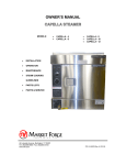
4200 & 4292 HALF SIZE ELECTRIC CONVECTION OVEN INSTALLATION - OPERATION - MAINTENANCE MODELS 4200 single oven 7292 double oven 44 Lakeside Avenue, Burlington, Vermont 05401 USA Telephone: (802) 658-6600 Fax: (802) 864-0183 www.mfii.com PN 14-0393 Rev A (9/14) © 2014 - Market Forge Industries Inc. Your Service Agency’s Address: Model Serial number Oven installed by Installation checked by TABLE OF CONTENTS IMPORTANT WARNING: Improper installation, adjustment, alternation, service or maintenance can cause property damage, injury or death. Read the installation, operation and maintenance instructions thoroughly before installing or servicing this equipment. FOR YOUR SAFETY Do not store or use gasoline or other flammable vapors or liquids in the vicinity of this or any other appliance. The information contained in this manual is important for the proper installation, use, and maintenance of this oven. Adherence to these procedures and instructions will result in satisfactory baking results and long, trouble free service. Please read this manual carefully and retain it for future reference. ERRORS: Descriptive, typographic or pictorial errors are subject to correction. Specifications are subject to change without notice. INSTALLATION Introduction.. . . . . . . . . . . . . . . . . . . . . . . . . . . . . . . . . . . . . . . . . . . . . . . . . . . . . . . . . . . . . . 2 Assembly to Legs. . . . . . . . . . . . . . . . . . . . . . . . . . . . . . . . . . . . . . . . . . . . . . . . . . . . . . . . . 3 Electrical Connection. . . . . . . . . . . . . . . . . . . . . . . . . . . . . . . . . . . . . . . . . . . . . . . . . . . . . . 5 OPERATION Control Panel. . . . . . . . . . . . . . . . . . . . . . . . . . . . . . . . . . . . . . . . . . . . . . . . . . . . . . . . . . . . . 6 Operating Instructions. . . . . . . . . . . . . . . . . . . . . . . . . . . . . . . . . . . . . . . . . . . . . . . . . . . . . 7 Introduction DESCRIPTION BASIC FUNCTIONING The Market Forge Model 4200 Electric Compact Convection Oven is an electrically powered convection oven designed to achieve high volume cooking with a minimum of power consumption. The unit consists of a heavily insulated cooking compartment fitted with a two speed convector blower and heated by electric elements. All oven controls are located on a panel on the right front of the oven as seen from the front. The Model 4200 becomes operational when the power switch is placed in the ON position, door is closed, and thermostat set. Contractors located in the control section close the circuit to heating elements located at the right of the cooking chamber. When the chamber reaches the preset temperature, the thermostat contacts open, causing the contractors to interrupt the circuit to the heating elements. When the temperature in the chamber drops enough to close the thermostat contacts, the circuit closes again. Any number of such cycles might occur during the cooking time, ~indicated by the element indicator light coming on and off. OVEN COMPONENTS The major assemblies of the model 4200 are the stainless steel and flat back painted steel cabinet enclosure, door with window, porcelain cooking compartment with nineposition shelf supports, heating element and contractor assembly, and control panel assembly. Controls and indicators include the thermostat, main power switch, blower speed switch, cool down/switch, elements on indicator light, 60-minute timer, and elements only switch. The oven is available in variety of mounting configurations: 4” 102mm high-legs, 27” 686mm legs with shelf, or stacked on top of another Model 4200 with the bottom unit on 18” 457mm stainless steel legs with shelf. SERVICE Required service, both preventive and corrective, is explained in section 5. Should repairs be required, a network of authorized agencies is available to assist with prompt service. A current directory of Authorized Service Agencies may be obtained on our website, www.mfii.com The model and serial number must be referenced when corresponding with Market Forge. The data plate with serial number is located on the right of the bottom front trim ledge. RECEIVING 1. Examine shipment for external and internal damage and completeness. Transport crated oven through building, to installation area before unpacking. 2. Report any damage or shortages to carrier and Market Forge immediately. 3. DO NOT AT ANY TIME LAY THE OVEN DOWN ON ITS TOP, RIGHT SIDE, OR FRONT. TO DO SO MAY DAMAGE THE EQUIPMENT AND VOID THE WARRANTY. INSTALLATION 2 Assembly to Legs 4200 SINGLE OVEN Single Oven on 4” Legs 7. Screw leg tops (item 2) into weld nuts by turning leg and top assemblies. Fasten legs to the weld nuts located on bottom panel of oven. The hex foot on the leg is adjustable. 8. Raise shelf (item 1) to desired height and tighten set screws in shelf corners. Single Oven on 28” Legs with Shelf 4. Insert legs (item 3) through holes in shelf (#1) Do not tighten setscrews in corners of shelf. 5. Screw leg tops (item 2) onto legs. (#3) 6. Insert leg tops (item 2) through holes in angle iron frame (#4) into weld nuts in bottom of oven. ITEM PART NO. 1 99-6180 2 DESCRIPTION QTY. SOLID SHELF ST/ST 1 A10-0635 LEG TOP 4 3 A10-0634 FLOOR LEG 28” HIGH 4 4 D99-6183 SHELF 1 Figure 1 3 INSTALLATION Assembly to Legs 4292 DOUBLE OVENS Stacked Ovens on 18” Legs with Shelf Assemble stand, as shown, before stacking ovens. 1. Fasten stacking channel (item 1), to the bottom left side of top oven. Note Left channel has (2) holes. Use nut & washer (items 3 & 4) front & rear. 2. Remove access panel from the right side of both ovens. 3. Remove knockouts from the top of the bottom oven and from the bottom of the top oven. 4. Place upper oven on top of lower oven with the right side stacking channel placed between. Line up holes in both ovens with the holes in the channel. 5. Fasten ovens together with the washer (item 4) and the bolt (item 11) Inserted up thru top of lower oven, thru stacking channel and into bottom of upper oven, using the existing weld nut to fasten the rear and the nut provided with the stacking kit (item 5) to fasten the front. ITEM PART NO. DESCRIPTION QTY. 1 B99-6203 Stacking Channel Left 1 2 B99-6204 Stacking Channel Right 1 3 10-2564 Hex Bolt 3/4-10 x 1-1/2 Lg. 2 4 10-2411 Plain Washer - 3/4 5 5 10-2320 Nut, Hex - 3/4 -10 1 6 99-6180 Solid Shelf 1 7 A09-5271 Floor Leg 18” High 4 8 A10-0635 Leg Top 4 9 D99-6183 Shelf 1 10 A25-3263 Set Screw & Wrench Kit 1 11 08-3426 Hex Bolt 3/4-10 x 4 Lg. 2 INSTALLATION Figure 2 4 Electrical Connection 1. Read data plate located on top surface of right side of bottom trim just below control panel before connecting electrical supply to oven. Make sure electrical supply is the same voltage, phase, and frequency called for on date plate. 2. All ovens are shipped three phase and may be converted to single phase as per alternate single phase wiring diagram. 3. Feed supply through opening in rear of oven and connect supply wires to terminal block behind control panel. 4. Wiring diagram label is located on control bracket, accessible by opening control panel. NOTE: Improper connection to power supply or connection to power supply other than that designated on data plate will void the warranty. 5 INSTALLATION Control Panel PRINCIPLES OF OPERATION Uniform distribution of heat within the oven is assured by continuous operation of a convector blower. Moving air continuously strips away a thin layer of moisture and cold air from the top of the food allowing more rapid heat penetration. Lower temperatures and shorter times than those used in conventional deck ovens ‘Can be used. In general, temperature settings can be reduced by 50°F (28°C) from recipe temperatures for conventional ovens. Some products may require slightly higher or lower temperatures. Product should be checked for doneness in about half the time it would take in a conventional oven. Time savings may be about 15% to 20%. CONTROLS All controls for the Model 4200 oven are located on the control panel on the front of the oven 1. Thermostat to control oven temperature 2. Elements On indicator light 3. Power switch with ON and OFF positions 4. Blower switch with high and low positions 5. Cool down switch with manual and auto positions 6. 60 minute electro-mechanical timer 7. Heating Elements Only Switch (Not Shown). Figure 3 OPERATION 6 Operating Instructions PRE-HEATING CLEANING 1. Set thermostat to desired temperature, set blower switch to desired speed, and turn on power switch. Blower wheel should rotate clockwise when viewed from front of oven. Low speed is suggested for fragile products ie those levened by beaten egg whites such as souffles, angel food cake and popovers. WARNING DO NOT HOSE DOWN UNIT AS IT CONTAINS ELECTRICAL COMPONENTS. 1. Clean interior of oven with a commercially available oven cleaner suitable for use on porcelain. 2. Indicator light will go out when desired temperature is reached. Oven will pre-heat to 350°F 180°C in about 10 minutes. Large differences in time from this indicate faulty heating elements, or connection to wrong electric power supply. 2. Racks, rack supports, and blower wheel may be cleaned by soaking in ammonia and water solution after removing them from oven. 3. Stainless steel parts maybe cleaned using a commercially available stainless steel cleaner. OPERATION 1. Set temperature about 50°F (28°C) less than what recipe calls for when using standard oven. 2. Load pans evenly on shelves making sure pans don’t touch sides of oven or other pans. 3. Check food for doneness in about half the time it would take in a conventional deck oven. Visual inspection of food can be made without opening the door by looking through tempered glass window. 4. Blower will automatically shut off by a door interlock switch when door opens. Closing the door will restart the blower. 5. Blower may be operated with door open by placing cool down switch in manual position. No power is suppled to heating elements with cool down switch in manual position, allowing rapid lowering of oven temperatures with door open. 6. Heating elements only without blower fan when door is shut. (For delicate products) 7 OPERATION