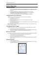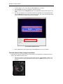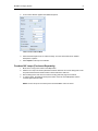
1
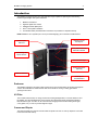
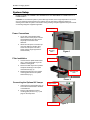
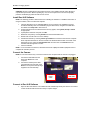
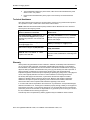
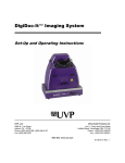
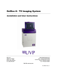
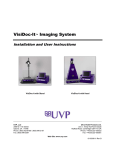
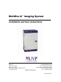
MultiDoc-It™ Imaging System
Installation and User Instructions
UVP, LLC
Ultra-Violet Products Ltd.
2066 W. 11th Street
Upland, CA 91786
Phone: (800) 452-6788 / (909) 946-3197
Fax: (909) 946-3597
Unit 1, Trinity Hall Farm Estate
Nuffield Road, Cambridge CB4 1TG UK
Phone: +44(0)1223-420022
Fax: +44(0)1223-420561
Web Site: www.uvp.com
81-0214-01 Rev K
MultiDoc-It Imaging System
2
Introduction
The MultiDoc-It Imaging System is a high resolution imager capable of capturing and documenting
fluorescent gel images. The system combines:
1.
2.
3.
4.
5.
MultiDoc-It Darkroom
DigiCam digital color camera
Ethidium Bromide (EtBr) Filter
®
Doc-It LS Acquisition Software
UV transilluminator (transilluminator instructions are provided in a separate manual)
NOTE: MultiDoc-It TLC Systems (for Thin Layer Chromatography) do not include a transilluminator.
Small footprint
darkroom
DigiCam camera
with diopter
Three position filter tray;
EtBr filter included
UV-blocking Gel
Viewer Window
Overhead white light
Side access doors
(optional)
Wide access door
Benchtop UV
Transilluminator
Darkroom
The MultiDoc-It darkroom provides a dark environment for gel UV illumination and protects the DigiCam
camera. Some MultiDoc-It models include side access doors for moving or cutting gels without
opening the front door.
UV Filter
The included emission filter, an orange-colored UV blocking bandpass filter, is used to absorb UV and
IR radiation from the transilluminator and to enhance the orange/pink bands generated by Ethidium
Bromide stained gels. The filter can be removed when imaging non-fluorescent media (protein gels,
colony plates, etc.) in order to produce brighter images.
Camera and Diopter
The DigiCam digital color camera includes a built-in optical zoom lens. A close-up diopter is connected
to the lens at the UVP factory.
MultiDoc-It Imaging System
3
Doc-ItLS Software
The Doc-ItLS software loads onto the user’s existing computer. The software controls the camera
acquisition functions as well as enhancement and reporting features. For information on operation of the
software, refer to the Doc-ItLS software help files.
Doc-ItLS Acquisition Software
UV Transilluminator
A UV transilluminator may be shipped with the system. Refer to the Transilluminator manual for
operating instructions.
Operating System Requirements
•
Windows 7, Vista or XP SP2 or later
•
Internet Explorer 6.0 or higher [To locate the version of Internet Explorer, open Internet
Explorer and click on Help > About Internet Explorer]
•
Intel Pentium Processor or equivalent, 1.6 GHz or higher
•
1 GB of RAM or greater
•
200 MB of available hard disk space for the program, more for data
•
CD-ROM drive
•
One Universal Serial Bus (USB) for connecting the camera
•
Color monitor, supporting at least 1024 x 768 resolution and 16-bit or better colors; 24-bit or
32-bit color is strongly recommended
NOTE: For 21 CFR Part 11 support functionality, the computer partition must be formatted with NTFS.
Refer to the Doc-ItLS software manual for instructions.
MultiDoc-It Imaging System
4
System Setup
DO NOT ATTEMPT TO CONNECT ANY WIRING WHILE THE EQUIPMENT IS CONNECTED TO A
POWER SUPPLY.
CAUTION: Do not install the system in places with high moisture, dust or high temperature. Do not use
any oil or petroleum based cleaner for the cabinet. Use only mild soap or detergent solution for
cleaning. Ensure that the system is turned OFF during cleaning. Keep the equipment away from motors
or other large magnetic equipment apparatus.
Head Screw
Power Connections
1.
2.
On the rear of the transilluminator,
attach one end of the jumper cord into
the transilluminator and other end of
the jumper cord to back of the
darkroom.
Attach the main power cord to the toprear of the darkroom and the other
end of the main power cord into a
power outlet (a surge suppressor is
recommended).
Filter Installation
1.
2.
3.
Camera
Mounting
Plate
Figure 1
Filter Tray
Unscrew the four plastic head screws
(Fig. 1) that hold the filter tray to the
camera mounting plate.
Remove the filter tray from its position
and place the filter(s) in the square
recessed areas (Fig. 2).
Reattach the filter tray to the camera
mounting plate with the four plastic
head screws (Fig. 1).
Filter Selector
Knob
Figure 2
Connecting the Optional UV Lamps
1.
2.
Lamp Outlets
Insert a lamp into each bracket (Fig. 3)
so that the cord is directed to the back
of the darkroom.
Run the cord behind the camera
mounting plate (shown in Fig. 1) and
plug into the lamp outlet.
Lamp Bracket
Figure 3
MultiDoc-It Imaging System
5
CAUTION: All UVP Transilluminators are powerful sources of UV radiation that will cause damage to
unprotected eyes and skin. Before operating any unit, be sure all personnel in the area are properly
protected. UV Blocking Eyewear should be worn as well.
Install Doc-ItLS Software
NOTE: The following provides a brief instruction for installing the software. For additional instruction on
using the software, refer to the Doc-ItLS help files.
1.
2.
3.
4.
Insert the flash drive into an available USB port on the computer. The installation program
should automatically start. If the installation program fails to start, navigate to the flash drive
and double-click setup.exe to launch Doc-It.
Follow instructions from the Wizard screens as they appear, clicking Next, Accept or Finish
as appropriate.
If prompted to restart the computer, click No.
Restart the computer by choosing Restart from the Windows Start menu.
5.
6.
Double click onto the UVP icon on the desktop.
Activate the software by choosing On the fly activation if connected to the Internet. Complete
all the required information on the form and fill in the Serial Number located on the back of the
flash drive’s tin box. Click onto Get Activation No. and then click onto Activate when the
Activation Number appears in the box.
7. Close the software.
NOTE: If not connected to the Internet, call technical services at (800) 452-6788 or (909) 946-3197 to
complete the activation process.
Connect the Camera
NOTE: It is recommended to only connect the camera to the computer while the camera is unplugged.
1.
2.
Connect the USB cable from the
back of the MultiDoc-It to the
computer.
Connect the camera power cable
(red and black) from the back of the
MultiDoc-It to a power outlet (a surge
suppressor is recommended).
Camera
Power
Cable
Camera
USB Cable
Connect to Doc-ItLS Software
1.
Open the Doc-ItLS software. The software should automatically identify the camera. The camera
control window should be active and ready to capture images.
MultiDoc-It Imaging System
6
System Operation
Darkroom Operation
1.
2.
3.
Turn on the green darkroom main power switch, located at the top of the MultiDoc-It darkroom.
The main power switch controls the automatic transilluminator shut off switch and the white
light power.
To use the transilluminator, once the main power switch is on, turn on the green
transilluminator power switch. If the darkroom door is opened, the transilluminator
automatically shuts off to prevent accidental UV exposure.
To use the overhead white light, switch the Overhead Light button to White.
Loading Samples Into the Darkroom
Samples are loaded into the MultiDoc-It darkroom through the front access door.
1.
Turn Off the UV Transilluminator.
2.
3.
4.
5.
Open the darkroom door.
Place the sample to be imaged in the center of the transilluminator filter glass.
Close the darkroom door.
Turn On the appropriate light source (UV transillumination, epi overhead white light or optional
epi overhead lamp modules).
Note: It is important to minimize the light source exposure to the sample. Turn off the light source as
soon as the image is captured.
View a Sample Prior to Capture
Samples may be viewed through the Gel Viewer Window when the main darkroom door is closed.
1.
2.
Open the Gel Viewer Window on the darkroom door.
After visually verifying that the sample is loaded correctly, close the Viewer. Otherwise, light
from the Viewer Window will interfere with the image capture process.
Move or Cut a Sample
It is possible to cut or move the sample by using the side access doors on the darkroom (if equipped).
1.
2.
3.
4.
Open the darkroom door and place the sample on the transilluminator.
Close the door and turn the transilluminator on.
Open the Gel Viewer Window on the darkroom door.
Open the side access door(s) and move or cut the gel while viewing the sample through the
Viewer window.
Software Operation
1.
2.
Open the Doc-ItLS software.
A window displaying the camera options should appear as pictured below. If not, click on the
Acquisition Action tab and then on the Camera menu button.
MultiDoc-It Imaging System
3.
4.
5.
6.
7
To take images in color, ensure that the Color Capture box is checked.
Select Preview at the top of the software to preview the image.
While in preview mode, the Brightness slider can be adjusted to brighten dark images or vice
versa.
The user may adjust the focus manually to enhance the appearance of the previewed image.
Click the Manual focus radio button on the Preview window, then use the left and right arrows
(shown in the red box, below) to adjust the focus settings.
Preview Window with Manual Focus
7.
When satisfied with the previewed image, select Capture at the top of the software.
Optional Camera Setup (Image Acquisition)
If operating the camera in automatic mode is not sufficient for the application, try utilizing the manual
mode to gain additional camera control.
1.
Access the camera by removing the emission filter tray (see “Filter Installation” earlier in this
manual) and turn the camera dial to M. (The dial is preset to A-DEP and will only turn in one
direction.)
Set Camera to M
MultiDoc-It Imaging System
2.
8
A new camera window appears with additional options:
Camera Control in Manual Mode
3.
4.
Select the desired options for an enhanced image. See the camera manual for detailed
descriptions of options.
Select Capture at the top of the software.
Overhead UV Lamps (Purchased Separately)
1.
Move the UV Lamp power switch to the ON position.
2.
Slide the UV Lamps into the lamp brackets inside the darkroom. Be sure the lamp power cords
are positioned toward the outlets located on back inside of the darkroom.
Run the lamp power cords over the camera mounting plate and plug into the outlets.
To use the lamps, the darkroom main power switch must to be in the ON position and the
overhead light switched to UV.
3.
4.
NOTE: The UV Lamps do not receive power until the MultiDoc-It door is closed.
MultiDoc-It Imaging System
9
Service Procedures
Return Procedure
A Returned Goods Authorization (RGA) number must be obtained from UVP Customer Service
before returning any product.
Replacement Parts and Accessories
Accessories are available for use with the MultiDoc-It Imaging Systems. Contact UVP’s offices at the
telephone numbers below for replacement parts for MultiDoc-It equipment. For transilluminator
replacement parts, refer to the separate transilluminator manual.
Description
Part Numbers
UV Lamps:
UVG-11, 254nm UV, 115V
UVG-11, 254nm UV, 230V
UVGL-15, 365/254nm, 115V
UVGL-15, 365/254nm, 230V
UVL-21, 365nm, 115V
UVL-21, 365nm, 230V
UVGL-25, 365/254nm, 115V
UVGL-25, 365/254nm, 230V
UV to 480nm Filter Converter
95-0016-14
95-0016-15
95-0017-09
95-0017-10
95-0018-02
95-0018-03
95-0021-12
95-0021-10
76-0310-01
Doc-ItLS Analysis Software
Thermal Printer, Mitsubishi Digital (115/230V)
Thermal Printer, Mitsubishi Digital (230V)
Thermal Printer, Sony Digital (230V for Europe)
Thermal Paper, matte 4 rolls (800 images)
Thermal paper, 16 rolls (3200 images)
Thermal Paper, 40 rolls (8000 images)
UV to White Light Converter Plate (21x26cm)
UV to White Light Converter Plate (20x40cm)
Visi-Blue Converter Plate (21x26cm)
Visi-Blue Converter Plate (20x40cm)
Filter, 50mm, sq., SYBR Green and EGFP
Filter, 50mm, sq., Ethidium Bromide
Fuse, 2 Amp, 250 V (Qty. 2)
Fuse Cap (Qty. 2)
97-0185-02
89-0069-06
89-0069-07
98-0357-01
89-0038-01
89-0038-04
89-0038-05
38-0191-01
38-0191-02
38-0200-01
38-0200-02
38-0219-01
38-0220-01
56-0002-01
56-0036-01
Troubleshooting
No Power to the Darkroom
1.
Recheck main power cord connections to the darkroom.
2.
Check fuses, located at the back of the unit, near the power port. A flat-head screwdriver
will be required. Turn the fuseholder cap counterclockwise and the fuse holder will pop
out. Inspect the thin wire within the glass fuse to see if there is a break in the wire. If so,
replace the fuse(s). If fuses are blowing repeatedly, contact UVP Technical Support for
additional troubleshooting.
Transilluminator Will Not Turn On
1.
There is a UV interlock switch that turns off the transilluminator and epi UV illumination
when the darkroom door is opened. Be sure the darkroom door is completely closed.
2.
Be sure the darkroom cabinet’s “Power On” indicator light is lit. If not, refer to “No Power
to the Darkroom” above.
MultiDoc-It Imaging System
10
3.
The transilluminator itself has a power switch; make sure that the transilluminator power
switch is in the “On” position.
4.
Ensure that the transilluminator power jumper cord is securely connected at both the
ends.
Technical Assistance
UVP offers expert technical support on all UVP products If there are any questions about product
use, operation or repair, contact UVP’s offices at the locations below.
NOTE: A Returned Goods Authorization (RGA) number must be obtained from UVP’s Customer
Service prior to returning any product.
If you are in North America, South
America, East Asia or Australia:
If you are in Europe, Africa, the Middle East or
Western Asia:
Call (800) 452-6788 or (909) 946-3197, and
ask for Technical Support during regular
business days, between 7:00 am and 5:00
pm, PST.
Call +44(0) 1223-420022, and ask for Customer
Service during regular business days between
9:00 am and 5:30 pm.
E-mail your message to: info@uvp.com or
techsupport@uvp.com
E-mail your message to: uvp@uvp.co.uk
Fax Technical Support at (909) 946-3597
Fax Customer Service at
+44(0) 1223-420561
th
Write to: UVP, LLC. 2066 W. 11 Street,
Upland, CA 91786 USA
Write to: Ultra-Violet Products Ltd. Unit 1, Trinity
Hall Farm Estate, Nuffield Road, Cambridge CB4
1TG UK
Warranty
UVP's products are guaranteed to be free of defects in materials, workmanship and manufacture for
one (1) year from date of purchase. Consumable and disposable parts including, but not limited to
tubes and filters, are guaranteed to be free from defects in manufacture and materials for ninety (90)
days from date of purchase. Transilluminators carry a two (2) year warranty from date of purchase. If
equipment failure or malfunction occurs during the warranty period, UVP shall examine the
inoperative equipment and have the option of repairing or replacing any part(s) which, in the judgment
of UVP, were originally defective or became so under conditions of normal usage and service.
No warranty shall apply to this instrument, or part thereof, that has been subject to accident,
negligence, alteration, abuse or misuse by the end-user. Moreover, UVP makes no warranties
whatsoever with respect to parts not supplied by UVP or that have been installed, used and/or
serviced other than in strict compliance with instructions appearing in this manual.
In no event shall UVP be responsible to the end-user for any incidental or consequential damages,
whether foreseeable or not, including but not limited to property damage, inability to use equipment,
lost business, lost profits, or inconvenience arising out of or connected with the use of instruments
produced by UVP. Nor is UVP liable or responsible for any personal injuries occurring as a result of
the use, installation and/or servicing of equipment.
This warranty does not supersede any statutory rights that may be available in certain countries.
Doc-It is a registered trademark of UVP, LLC. MultiDoc-It is a trademark of UVP, LLC.