1
Operator's
Manual
M
2-Cycle
Electric Start Capable
WEEDWACKER® GAS TRIMMER
Model No. 316.990110
U_F_VABLE
STArTinG
EA $ E _
,, SAFETY
* ASSEMBLY
* OPERATION
CAUTION: Before using this product,
read this manual and follow all its Safety
Rules and Operating
instructions.
Sears Brands
Management
* PARTS LIST
* ESPANOL, R 23
Corporation,
Visit our website:
769-07591 P00
* MAINTENANCE
Hoffman
Estates,
IL 60179 U.S.A.
www.craftsman.com
12/11
TABLEOFCONTENTS
Safety...............................................
Warranty.............................................
KnowYourUnit........................................
Specifications
.........................................
Assembly
.............................................
OilandFuel...........................................
Starting
andStopping
..................................
Operation
............................................
Maintenance
.........................................
Cleaning
andStorage..................................
SpeedStart Accessory ...............................
TM
Troubleshooting .......................................
Repair Protection Agreements
...........................
Parts List ............................................
Service Numbers ..............................
2
5
6
6
7
9
10
12
13
17
18
19
21
46
Back Cover
All information, illustrations and specifications in this manual are based
on the latest product information available at the time of printing. We
reserve the right to make changes at any time without notice.
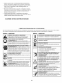
The purpose of safety symbols is to attract your attention to
possible dangers. The safety symbols, and their explanations,
deserve your careful attention and understanding. The safety
warnings do not by themselves eliminate any danger. The
instructions or warnings they give are not substitutes for proper
accident prevention measures.
SYMBOL
MEANING
DANGER:
Signals an EXTREME hazard.
Failure to obey a safety DANGER signal WILL result in
serious injury or death to yourself or to others.
WARNING:
Signals a SERIOUS hazard.
Failure to obey a safety WARNING signal CAN result in
serious injury to yourself or to others.
CAUTION:
Signals a MODERATE hazard.
Failure to obey a safety CAUTION signal MAY result in
property damage or injury to yourself or to others.
NOTE: Advises you of information or instructions
operation or maintenance of the equipment.
SPARK ARRESTOR NOTE
NOTE: For users on U.S. Forest Land and in the states of
California, Maine, Oregon and Washington. All U.S. Forest Land
and the state of California (Public Resources Codes 4442 and
4443), Oregon and Washington require, by law that certain internal
combustion engines operated on forest brush and/or grass-covered
areas be equipped with a spark arrestor, maintained in effective
working order, or the engine be constructed, equipped and
maintained for the prevention of fire. Check with your state or local
authorities for regulations pertaining to these requirements. Failure
to follow these requirements could subject you to liability or a fine.
This unit is factory equipped with a spark arrestor. Replacement
requires Muffler Assembly Part #753-06418, installed at a Sears
Parts & Repair Service Center.
CALiFORNiA
PROPOSITION
65
WARNING:
Engine exhaust, some of its constituents and
certain finished components contain or emit chemicals known
to the State of California to cause cancer and birth defects or
other reproductive harm. Wash hands after handling.
vital to the
Read the operator's manual and follow all warnings and safety
instructions. Failure to do so can result in serious injury to the
operator and/or bystanders.
• iMPORTANT SAFETY iNSTRUCTiONS
READ ALL iNSTRUCTiONS
BEFORE OPERATING
The trimmer attachment shield must always be in place while
operating the unit. Do not operate unit without both trimming
lines extended, and the proper line installed. Do not extend the
trimming line beyond the length of the shield.
This unit has a clutch. The cutting head remains stationary when
the engine is idling. If it does not, take the unit to a Sears or
other qualified service dealer for an adjustment.
Adjust the handle to provide the best grip.
Be sure the trimmer attachment is not in contact with anything
before starting the unit.
Use the unit only in daylight or good artificial light.
Avoid accidental starting. Be in the starting position whenever
pulling the starter rope. The operator and unit must be in a stable
position while starting. Refer to Starting and Stopping.
I'1
WARNING:
When using the unit, all safety rules must be
followed. Please read these instructions before operating
the unit in order to ensure the safety of the operator and any
bystanders. Please keep these instructions for later use.
o
o
o
o
o
o
Read the instructions carefully. Be familiar with the controls and
proper use of the unit.
Do not operate this unit when tired, ill or under the influence of
alcohol, drugs or medication.
Children must not operate the unit. Teens must be accompanied
and guided by an adult.
Inspect the unit before use. Replace damaged parts. Check for
fuel leaks. Make sure all fasteners are in place and secure.
Replace parts that are cracked, chipped, or damaged in any way.
Only use the trimming line described in the Specifications section
of this manual. Never use metal-reinforced line, wire, chain or
rope. These can break off and become dangerous projectiles.
Be aware of risk of injury to the head, hands and feet.
Clear the area to be cut before each use. Remove rocks, broken
glass, nails, wire, string and other objects which may be thrown
or become entangled in the trimmer attachment. Clear the area
of children, bystanders and pets; keep them outside a 50-foot
(15 m) radius, at a minimum. Even then, they are still at risk from
thrown objects. Encourage bystanders to wear eye protection. If
you are approached, stop the unit immediately.
Squeeze the throttle control and check that it returns
automatically to the idle position. Make all adjustments or
repairs before using the unit.
Use the right tool. Only use this tool for its intended purpose.
Always hold the unit with both hands when operating. Keep a
firm grip on both handles or grips.
Keep hands, face, and feet away from all moving parts. Do not
touch or try to stop the trimmer attachment when it rotates.
Do not touch the engine, gear housing or muffler. These parts get
extremely hot from operation, even after the unit is turned off.
Do not operate the engine faster than the speed needed to cut, trim
or edge. Do not run the engine at high speed when not cutting.
Always stop the engine when cutting is delayed or when walking
from one cutting location to another.
If you strike or become entangled with a foreign object, stop the
engine immediately and check for damage. Do not operate
before repairing damage. Do not operate the unit with loose or
damaged parts.
•
SAFETY WARNINGS FOR GAS UNITS
can explode if ignited.
the following
WARNING:
GasolineTake
is highly
flammableprecautions:
and its vapors
•
]
Store fuel only in containers specifically designed and approved
for the storage of such materials.
Always stop the engine and allow it to cool before filling the
tank. Never remove the fuel tank cap or add fuel when the
engine is hot. Always loosen the fuel tank cap slowly to relieve
any pressure in the tank before fueling.
Always mix and add fuel in a clean, well-ventilated outdoor area
where there are no sparks or flames. DO NOT smoke.
Turn the engine to off and disconnect the spark plug for
maintenance or repair.
Use only original equipment manufacturer (OEM) replacement
parts and accessories for this unit, as listed in the Parts List
section of this manual. Use of any other parts or accessories
could lead to serious injury to the user, or damage to the unit,
and void the warranty.
Keep the unit clean of vegetation and other materials that may
become lodged between the cutting head and shield.
To reduce fire hazard, replace a faulty muffler and spark arrestor.
Keep the engine and muffler free from grass, leaves, excessive
grease or carbon build up.
OTHER SAFETY WARNINGS
Never store the unit with fuel in the tank, inside a building where
fumes may reach an open flame (pilot lights, etc.) or sparks
(switches, electrical motors, etc.).
Allow the engine to cool before storing or transporting. Be sure
to secure the unit while transporting.
Never operate the unit without the fuel cap securely in place.
Avoid creating a source of ignition for spilled fuel. Wipe up any
spilled fuel from the unit immediately, before starting the unit.
Move the unit at least 30 ft. (9.1 m) from the fueling source and
site before starting the engine. DO NOT smoke.
Never start or run the unit inside a closed room or building.
Breathing exhaust fumes can kill. Operate this unit only in a well
ventilated outdoor area.
Store the unit in a dry place, secured or at a height to prevent
unauthorized use or damage. Keep out of the reach of children.
Never douse or squirt the unit with water or any other liquid.
Keep handles dry, clean and free from debris. Clean after each
use, see Cleaning and Storage instructions.
Keep these instructions. Refer to them often and use them to
instruct other users. If you loan this unit to others, also loan
them these instructions.
WHILE OPERATING
Wear safety glasses or goggles that meet current ANSI
standards and are marked as such. Wear ear/hearing protection
when operating this unit. Wear a face or dust mask if the
operation is dusty.
Wear heavy long pants, boots, gloves and a long sleeve shirt. Do
not wear loose clothing, jewelry, short pants, sandals or go
barefoot. Secure hair above shoulder level.
SAVE THESE iNSTRUCTiONS
3
,,SAFETY
& iNTERNATiONAL
SYMBOLS
,,
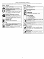
This operator's manual describes safety and international symbols and pictographs that may appear on this product. Read the operator's
manual for complete safety, assembly, operating and maintenance and repair information.
SYMBOL
L_
_j_
I
MEANING
SYMBOL
MEANING
|
' eIndicates
danger, SYMBOL
warning or caution: May be use d in
SAFETY ALERT
conjunction with other symbols or pictographs:
WAR NING: Read the operato_!S manUa!(s)and
,, fol!ow
READ all
OPERATOR'S
warnings andMANUAL
safety instruct!ons: Failure to
do so can result in serious injury to the operator
........
. and!or bystanders,
O
" OFF
ON/OFF
or STOP
STOP CONTROL
, PRIMER
BULB
rJi
_rJ
4t
_---I_
Push primer bulb fully and slowly
WARNING:
ThrOwn
objects
andloud
noise
_ o WEAR EYE AND HEARING PROTECTION
_= cause
severe
eye injury
andANSI
hearing
!0ss. wear
Protection
meeting
Current
standards
and eye
ear
H
I<1 I{°1
protection when operating this unit. Use a full face
shield when needed.
AlwayS Use clean, fresh Unleaded fuel.
10 times.
J CHOKE CONTROL
1., FULLchoke position
2. • PARTIAL choke position
3. • RUN choke position
__17_
/ _
/_JT//
S-_,_
_THROWN OBJECTS AND ROTATING CUTTER CAN
CAUSE SEVERE INJURY
WARNING: Small objects can be propelled at high
speed, causing injury. Keep away from the rotating rotor.
oOIL
Refer t0 operators; manual for the proper tYpe Of oil.
WARNING: Keep all bystanders especially children
t KEEP
BYSTANDERS
AWAY
and pets,
at least 50 feet
(15 m) from the operating area
@
WARNING:it
haS been proven that fUe! c0ntaining
greater
than
10%
willTHIS
likelyUNIT
damage this
oDO NOTUSE E85ethanol
FUEL IN
engine and void the warranty.
_
" HOT SURFACE
You
may get burned.
extremely
hot
ARNING:
Do not These
touch parts
a hot get
muffler
or cylinder.
. from operation. When turned off they remain hot for a
, short time.
WARNING:
._'
Sharp blade on trimmer attachment
shield.
prevent serious injury, do not touch the line
SHARPToBLADE
cutting blade.
CRAFTSMAN
TWO
YEAR FULL
WARRANTY
FOR TWO YEARS from the date of purchase, this product is warranted against any defects in material or workmanship.
will be replaced free of charge.
For warranty coverage details to obtain free replacement, visit the web site: www.craftsman.com
This warranty covers ONLY defects in material and workmanship. Warranty coverage does NOT include:
•
A defective product
Expendable items that can wear out from normal use within the warranty period, such as cutting line, spark plugs, or filters.
Product damage resulting from user attempts at product modification or repair or caused by product accessories.
Repairs necessary because of accident or failure to operate or maintain the product according to all supplied instructions.
Preventive maintenance, or repairs necessary due to improper fuel mixture, contaminated or stale fuel.
This warranty is void if this product is ever used while providing commercial services or if rented to another person.
This warranty gives you specific legal rights, and you may also have other rights which vary from state to state.
Sears Brands Management
Corporation,
Hoffman Estates, IL 60179
5
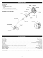
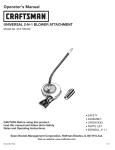
APPLiCATiONS
As a trimmer:
•
Muffler
Spark Plug
Cutting grass and light weeds.
Starter
•
•
Decorative trimming around trees, fences, etc.
Edging
Rope Grip "_4k_' __
Other optional accessories may be used with this unit.
NO ASSEMBLY
TOOLS
Shaft Grip.
REQUIRED
Handle
__
Shaft Housing
Choke Lever
_// _i
_
_
_'_'_'_'_ AircoverFilter
Fuel Cap
Control
_
_
-
//vj
Line Cutting Blade.
_
/'4k_"
Convertible
Throttle
TM
Primer
Bulb
_//C°upler
Head_
z/• /
7
Cutting
Shield
Cutting Hea
Engine Type ........................................................................................
Displacement .......................................................................................
Idle Speed RPM ......................................................................................
Operating RPM ...........................................................................................
Spark Plug Gap ....................................................................................
Spark Plug ..........................................................................
Lubrication ...........................................................................................
Champion®
Fuel/Oil Ratio ..................................................................................................
Fuel Tank Capacity ......................................................................................
Approximate Unit Weight (No fuel, with cutting head, cutting head shield and handle) ...........................
Trimmer Mechanism .......................................................................................
Trimming Line Diameter ...........................................................................
Cutting Path Diameter ..................................................................................
* All specifications are based on the latest product information
time without notice.
Air-Cooled, 2-Cycle
25 cc (1.52 cu. in.)
2,800 - 3,400 rpm
6,300+ rpm
0.025 in. (0.635 mm)
RDJ7J or equivalent plug
Fuel/Oil Mixture
40:1
10 oz. (296 ml)
10 - 11 Ibs. (4.5 - 5 kg)
Bump Head
0.095 inches (2.41 mm)
17 in. (43.18 cm)
available at the time of printing. We reserve the right to make changes at any
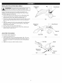
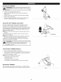
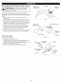
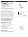
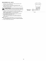
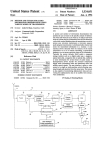
iNSTALLiNG
THE CUTTING
HEAD
SHIELD
Slot
cutting Head
Shield
_
operate the unitTowithout
cuttingpersonal
head shield
place.
WARNING:
preventthe
serious
injury,innever
1
|
Mount Bracket
]
Use the following instructions if the cutting head shield is not
installed. Use only the instructions that apply to the type of shaft
and shield equipped with this unit.
1. Remove the wing nut and washer from the cutting head shield.
2.
Insert the short tab (the one without a hole) on the mount
bracket into the slot on the cutting head shield (Fig. 1).
3. Rotate the cutting head shield counterclockwise to align the hole
on the cutting head shield with the hole on the mount bracket
(Fig. 1).
4. Insert the square bolt into the hole underneath the cutting head
shield (Fig. 2). Push the square bolt through the cutting head
shield and mount bracket.
5. Put the washer onto the square bolt (Fig. 2).
6. Screw the wing nut onto the square bolt until the cutting head
shield is firmly in place (Fig. 2).
Fig. 1
Mount
Cutting Head
Shield
Bracket
Wing Nut
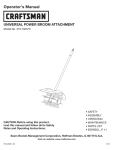
ADJUSTING THE HANDLE
Square Bolt
If the handle requires adjustment:
1. Loosen the wing nut (Fig. 3).
2. While holding the unit in the operating position (Fig. 10), move
the handle to the location that provides the best grip. Place it a
minimum of 6 inches (15.24 cm) from the end of the shaft grip
(Fig. 3).
3. Tighten the wing nut until the handle is secure.
Washer
Fig. 2
Shaft Grip
Handle
Tighten
Minimum
6 in.
{15.24 cm}
Wing Nut
Bolt
Washer
Fig. 3
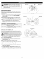
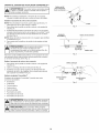
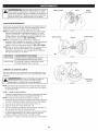
OPERATING THE CONVERTIBLE
TM
COUPLER SYSTEM
|
[__J
1
damage to the unit, shut the unit off before removing or
WARNING:
To avoid serious personal injury and
installing an attachment.
NOTE: To make installing or removing the attachment
the unit on the ground or on a work bench.
installing
the Trimmer
Attachment
|
easier, place
or Other Attachment
NOTE: Remove the protective cap and gray spacer from the upper
and lower shafts prior to assembling the attachment.
1. Turn the knob counterclockwise to loosen (Fig. 4).
2. While firmly holding the trimmer attachment or other attachment,
push it straight into the Convertible TM coupler until the release
button snaps firmly into the primary hole (Fig. 6).
NOTE: Aligning the release button with the guide recess will help
installation (Fig. 5).
3.
90° Edging Hole
(Trimmer Only)
Knob
Fig. 4
Convertible
TM
Release Button
Coupler
Turn the knob clockwise to tighten (Fig. 4).
c,o,,oo
e,o eo
esu
eratn
! ethatthe
thsunt
release button is fully snapped into the primary hole (Fig. 6),
and that the knob (Fig. 4) is securely tightened.
For decorative edging with the line head trimmer attachment, lock
the release button of the attachment into the 90 ° hole (Fig. 4).
Removing
the Trimmer Attachment
Guide Recess
or Other Attachment
Fig. 5
1. Turn the knob counterclockwise to loosen (Fig. 4).
2. Press and hold the release button (Fig. 5).
3. While firmly holding the upper shaft housing, pull the trimmer
attachment or other attachment straight out of the Convertible
coupler (Fig. 6).
The Convertible
The Convertible
attachments.
TM
TM
TM
Primary Hole
Coupler System
coupler system enables the use of these optional
•
•
•
•
•
Edger
Cultivator
Turbo Blower
Brushcutter
Pole Saw
•
•
•
Hedge Trimmer
Straight-shaft trimmer
Curved-shaft trimmer
Upper Shaft
Housing
Lower Shaft
Housing
Fig. 6
1
_
read and understand the manual that came with the
ARNING; Follow
Beforeall you
begin
using anycontained
attachment,
attachment.
safety
information
within. |
_
the primary hole only. Using the wrong hole could lead to
CAUTION:
attachments
are to be snapped into
personal injuryThese
or damage
to the unit.
l
FUELING THE UNiT
OiL AND FUEL MiXiNG iNSTRUCTiONS
The use of old and/or improperly mixed fuel is the most common cause
of performance problems. Use only fresh, clean unleaded gasoline.
Follow the instructions carefully for the proper gasoline/oil mixture.
Definition of Blended
WARNING:
Gasoline is extremely flammable. Ignited
vapors may explode. Always stop the engine and allow it
to cool before filling the fuel tank. Do not smoke while
filling the tank. Keep sparks and open flames at a distance
from the area.
Fuels
Today's fuels are often a blend of gasoline and oxygenates such as
ethanol, methanol or MTBE (ether). Alcohol-blended fuel absorbs
water. As little as 1% water in the fuel can make fuel and oil
separate, forming acids when stored. ALWAYS use fresh fuel (less
than 30 days old).
NOTE: Dispose of old fuel according to federal, state and local
regulations.
Using Blended
WARNING:
Remove the fuel cap slowly to avoid injury
from fuel spray. Never operate the unit without the fuel cap
securely in place.
WARNING:
Add fuel in a clean, well ventilated outdoor
area. Wipe up any spilled fuel immediately. Avoid creating
a source of ignition for spilled fuel. Do not start the engine
until fuel vapors dissipate.
Fuels
If using a blended fuel:
• Always use the fresh fuel mix explained in your operator's manual
Use the fuel additive STA-BIL® or an equivalent
Always agitate the fuel mix before fueling the unit
Drain the tank and run the engine dry before storing the unit
1. Position the unit with the fuel cap facing up.
2. Remove the fuel cap.
3. Place the fuel container spout into the fill hole on the fuel tank
and fill the tank.
NOTE: Do not overfill the tank.
I
J
has been proven that fuel containing greater than 10%
_WARNING:
DOdamage
NOT USE
FUEL
THIS
It
|
ethanol will likely
this E85
engine
andINvoid
theUNIT.
warranty.
Using Fuel Additives
The bottle of 2-cycle oil provided with this unit contains a fuel
additive to help inhibit corrosion and minimize gum deposits.
Always use the brand of 2-cycle oil that came with this unit. If this is
unavailable, use a 2-cycle oil designed for air-cooled engines and
mix it with a fuel additive, such as STA-BIL Fuel Stabilizer or an
equivalent. Add 0.8 oz. (23 ml) of fuel additive per gallon of fuel,
according to the instructions on the container. NEVER add fuel
additives directly to the unit's fuel tank.
Mixing the Fuel
NOTE: This unit comes with a 3.2 oz. bottle of 2-cycle oil. To obtain
the correct fuel mixture described below, pour the entire bottle
into one gallon of unleaded gasoline.
CAUTION:
For proper engine operation and maximum
reliability, pay strict attention to the gasoline and oil mixing
instructions on the 2-cycle oil bottle. Using improperly
mixed fuel can severely damage the engine.
Thoroughly mix the proper ratio of unleaded gasoline with 2-cycle
engine oil. Do not mix them directly in the unit's fuel tank. Use a
separate fuel can. Use a 40:1 gasoline/oil ratio. See the table below
for specific gasoline and oil mixing ratios.
Unleaded gasoline
2=cycle oil
1 gallon U.S.
(3.8 liters}
3.2 fL oz.
1 liter
25 rnl
(95 ml)
MIXING RATIO = 40:1
9
4.
5.
6.
Wipe up any fuel that may have spilled.
Reinstall the fuel cap.
Move the unit at least 30 ft. (9.1 m) from the fuel container and
the fueling site before starting the engine.
!
outdoor area. Carbon monoxide exhaust fumes can be
I_
I WARNING:
lethal in a confined
Operate
area.this unit only in a well-ventilated
[__J
serious injury, the operator and the unit must be in a stable
ARNING:
starting
position
when Avoid
pulling accidentally
the starter rope
(Fig.the
9). unit. To avoid
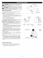
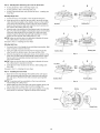
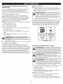
STARTING
J
INSTRUCTIONS
1. Mix gasoline with oil. Refer to Oil and Fuel Mixing Instructions.
2. Fill the fuel tank. Refer to Fueling the Unit.
NOTE: There is no need to turn the unit on. The On/Off switch is in
the ON (I) position at all times (Fig. 7).
3. Slowly press and release the primer bulb 10 times (Fig. 8). If fuel
cannot be seen in the primer bulb, press and release the primer
bulb until fuel is visible.
4.
5.
Move the choke lever to Position 1 (Fig. 8).
Crouch in the starting position (Fig. 9).
6.
Squeeze the throttle control (Fig. 7) and pull the starter rope with
a controlled and steady motion 5 times (Fig. 9).
Throttle Control
Fig. 7
Choke Lever
NOTE: SQUEEZE and HOLD the throttle control for ALL further steps.
NOTE: This unit uses the INCREDI-PULL TM starting system, which
significantly reduces the effort required to start the engine.
7. Continue to squeeze the throttle control. Move the choke lever
to Position 2 (Fig. 8).
8. Continue to squeeze the throttle control. Pull the starter rope with
a controlled and steady motion 3 to 5 times to start the engine.
9. Continue to squeeze the throttle control. Allow the engine to
warm up for 30 to 60 seconds.
10. Continue to squeeze the throttle control. Move the choke lever
to Position 3 (Fig. 8) and continue warming the engine for an
additional 60 seconds. The unit may be used during this time.
Position 1
Position 2
Position 3
Fig. 8
Starter Rope Grip
Starting
Position
NOTE: The engine is properly warmed up when it accelerates
without hesitation.
IF... the engine hesitates, return the choke lever to Position 2 (Fig. 8)
and continue the warm-up.
IF... the engine does not start, begin the starting procedure with
step 3.
IF... the engine fails to start after a few attempts, move the choke
lever to Position 3 and squeeze the throttle control. Pull the
starter rope with a controlled and steady motion 3 to 8 times.
The engine should start. If it does not, repeat this instruction.
IF... the engine is already warm, begin the starting procedure with
step 7.
STOPPING
1.
2.
Primer Bulb
Throttle Control
Fig. 9
iNSTRUCTiONS
Release the throttle control and allow the engine to idle.
Press and hold the On/Off switch in the OFF (O) position until
the engine comes to a complete stop (Fig. 7).
10
i!lllIi!!!:!!ilii!!!i]i!
i ii!il!!!!i!Ii!; iiiii!t!iiii
t
!!!! iii 11i!i!i!ii!l!iiilll
NOTE: This unit can use a Speed Start TM Accessory!
Please refer to the Speed Start TM accessory operator's manual
for the proper use of this feature. (Items Sold Separately! Refer
to the Speed Start TM Accessory section of this manual for more
information about these Speed Start TM accessories.)
STARTING iNSTRUCTiONS
1.
Mix gasoline with oil. Refer to Off and Fuel Mixing instructions.
2. Fill the fuel tank. Refer to Fueling the Unit.
NOTE: There is no need to turn the unit on. The On/Off switch is in
the ON (I) position at all times (Fig. 7).
3. Slowly press and release the primer bulb 10 times (Fig. 8). If fuel
cannot be seen in the primer bulb, press and release the primer
bulb until fuel is visible.
4. Move the choke lever to Position 1 (Fig. 8).
5. Crouch in the starting position (Fig. 9).
6. Insert the Speed Start TM accessory into the Speed Start TM port
(Fig. 23). Refer to the Operation section of the Speed Start TM
accessory operator's manual.
7. Squeeze and hold the throttle control (Fig. 7). Run the Speed
Start TM accessory for 2 seconds.
NOTE: SQUEEZE and HOLD the throttle control for ALL further steps.
8. Continue to squeeze the throttle control. Move the choke lever
to Position 2 (Fig. 8).
9. Continue to squeeze the throttle control. Run the Speed Start TM
accessory in intervals no longer than 2 seconds each until the
unit starts.
10. Remove the Speed Start TM accessory from the unit.
11. Continue to squeeze the throttle control. Allow the engine to
warm up for 30 to 60 seconds.
12. Continue to squeeze the throttle control. Move the choke lever
to Position 3 (Fig. 8) and continue warming the engine for an
additional 60 seconds. The unit may be used during this time.
NOTE: The engine is properly warmed up when it accelerates
without hesitation.
iF... the engine hesitates, return the choke lever to Position 2 (Fig. 8)
and continue the warm-up.
iF... the engine does not start, begin the starting procedure with
step 3.
iF... the engine fails to start after a few attempts, move the choke
lever to Position 3 and squeeze the throttle control. Run the
Speed Start TM accessory in intervals no longer than 2 seconds
each until the unit starts. The engine should start. If it does not,
repeat this instruction.
iF... the engine is already warm, begin the starting procedure with
step 8.
STOPPING
1.
2.
iNSTRUCTiONS
Release the throttle control and allow the engine to idle.
Press and hold the On/Off switch in the OFF (O) position until
the engine comes to a complete stop (Fig. 7).
11
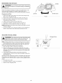
HOLDINGTHE
i
•
•
•
•
•
TRIMMER
body protection
this unit.
to reduce
heha
'i 0,, Ioota
the risk of injury when operating
Stand in the operating position (Fig. 10).
Hold the shaft grip with the right hand. Keep the right arm
slightly bent.
Hold the handle with the left hand. Keep the left arm straight.
Hold the unit at waist level,
Keep the cutting head parallel to the ground so that it easily
contacts the grass without the need for bending over.
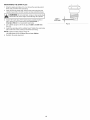
ADJUSTING THE TRIMMING
Fig. 10
LINE LENGTH
This unit is equipped with a Bump Head. Trimming line can be
released from the cutting head without stopping the engine.
To release more line, lightly tap the bump knob on the ground (Fig. 11)
while operating the unit at high speed. For best results, tap the bump
knob on bare ground or hard soil. Attempting to release line in tall
grass may stall the engine.
NOTE: Do not rest the cutting head on the ground while the unit is
running.
Each time the bump knob is tapped, about 1 inch (25.4 mm) of
trimming line is released.
NOTE: Always keep the trimming line fully extended. Line release
becomes more difficult when the cutting line gets shorter.
A blade in the cutting head shield will cut the line to the proper
length if any excess line is released.
Bump Knob
Fig. 11
CAUTION:
Do not remove or alter the line cutting blade
assembly. Excessive line length will make the unit
overheat. This may lead to serious personal injury or
damage to the unit.
TiPS FOR BEST TRIMMING
•
RESULTS
Keep the cutting head parallel to the ground.
Cut from left to right whenever possible. This improves the unit's
cutting efficiency and throws clippings away from the operator.
Do not trim wet grass or weeds.
NOTE: Some line breakage will occur from:
Entanglement with foreign matter
Normal line fatigue
Attempting to cut thick vegetation
Forcing the line into objects such as walls or fence posts
DECORATIVE
\
TRIMMING
When trimming around trees, posts, fences, etc., rotate the whole
unit so that the cutting head is at a 30 ° angle to the ground (Fig. 12).
Fig. 12
12
WARNING:
To prevent serious injury, never perform
maintenance or repairs while the unit is running. Always
allow the unit to cool before servicing or repairing the unit.
Disconnect the spark plug wire to prevent the unit from
starting accidentally.
MAINTENANCE
Outer
Bolt
Bump Knob
SCHEDULE
Perform these required maintenance procedures at the frequency
stated in the table. These procedures should also be a part of any
seasonal tune-up.
NOTE: Some maintenance procedures may require special tools or
skills. If unsure about these procedures, take the unit to a Sears
or other qualified service dealer. Call 1-800-4-MY-HOME
for
more information.
/
/
Fig. 13
Outer Spool
NOTE: Maintenance, replacement, or repair of the emission control
devices and system may be performed by a Sears or other qualified
service dealer. Call 1=800-4-MY-HOME for more information.
NOTE: Please read the California/EPA statement that came with the
unit for a complete listing of terms and coverage for the
emissions control devices, such as the spark arrestor, muffler,
carburetor, etc.
FREQUENCY
MAINTENANCE
Every 10 hours
Clean and re-oil the air filter. Refer to
Maintaining the Air Filter.
Every 25 hours
Check the spark plug condition and gap. Refer
to Maintaining the Spark Plug.
Spring
\
inner Reel
,
REQUIRED
Shaft
Fig. 14
indexing Teeth
REPLACING
THE TRiMMiNG
LiNE
Only use the trimming line described in the Specifications section.
Other types of trimming line may cause the engine to overheat or fail.
_
rope. These canNever
breakuse
off metal-reinforced
and become dangerous
WARNING:
line, wire,projectiles.
chain or
]
NOTE: Always use the correct line length when installing trimming
line. The line may not release properly if the line is too long.
Part 1 - Removing
Holding
Fig. 15
the inner Reel
1.
Hold the outer spool with one hand and unscrew the bump knob
counterclockwise (Fig. 13).
NOTE: The outer spool will remain attached to the unit.
2. Inspect the bolt inside the bump knob to make sure it moves freely.
Replace the bump knob if it is damaged.
3. Remove the inner reel from the outer spool (Fig. 14).
4. Remove the spring from the inner reel (Fig. 14).
5. Use a clean cloth to clean the inner reel, spring, shaft and inner
surface of the outer spool.
6. Check the indexing teeth and holding slots for wear (Fig. 15). If
necessary, remove burrs or replace the inner reel and outer spool.
Proceed to Part 2 - Winding New Trimming Line onto the inner Reel.
13
Slots
Part 2 - Winding
=
•
New Trimming Line onto the inner Reel
A
B
If using single line, refer to Winding Single Line.
If using split line, refer to Winding Split Line.
If using a prewound inner reel, proceed to Part 3 - Installing the
Inner Reel.
Winding
Single Line
1. Cut two 8-foot (2.4 m) lengths of new single trimming line.
2. Insert the end of one line into the top hole in the inner reel (Fig.
16A). Wind the line tightly in the direction shown on the bottom
of the inner reel until about 6 inches (150 mm) of line remains.
Keep the line above the split wall. Insert the 6-inch section into
the nearest .095 holding slot (Fig. 16B).
3. Insert the end of the other line into the bottom hole in the inner reel
(Fig. 17A). Wind the line tightly in the direction shown on the bottom
of the inner reel until about 3 to 9 inches (75 to 225 mm) of line
remains. Keep the line below the split wall. insert the 3 to 9-inch
section into the opposite .095 holding slot (Fig. 17B).
NOTE: Failure to wind the line in the direction indicated will cause
the cutting head to operate incorrectly.
Proceed to Part 3 - Installing the Inner Reel.
Winding
Holding Slot
Top Hole
Fig. 16
A
B
Wall
Split Line
1. Cut one 6-foot (1.8 m) length of new split line trimming line. Split
each end about 6 inches (150 mm).
2. Using one split end, insert one line into the top hole and the
other line into the bottom hole in the inner reel (Fig. 18A).
3. Wind the line tightly in the direction shown on the bottom of the
inner reel. The split wall will automatically divide the line. Wind
the line until it is completely divided and about 6 inches (150
mm) of line remains.
NOTE: Failure to wind the line in the direction indicated will cause
the cutting head to operate incorrectly.
4. Insert the two 6-inch sections into the two .095 holding slots
(Fig. 18B).
Proceed to Part 3 - Installing the Inner Reel.
Bottom
Holding Slot
Hole
Fig. 17
B
Split
Wall
Part 3 - Installing the inner Reel
1.
Pass the two line ends through the eyelets in the outer spool.
Place the spring inside the inner reel. insert the inner reel into
the outer spool. Push the inner reel and outer spool together
(Fig. 19).
NOTE: The spring must be assembled on the inner reel before
reassembling the cutting head.
2. While holding the inner reel and outer spool together, firmly pull
the two line ends to release them from the holding slots.
Bottom
Hole
Holding Slots
Fig. 18
Outer Spool
3. While holding the inner reel and outer spool together, screw the
bump knob on clockwise. Tighten the bump knob securely.
Eyelets _
Spring
i
inner Reel
_
Bump Knob
Fig. 19
14
MAiNTAiNiNG
THE AiR FILTER
Air Filter
J
the engine and allow it to cool before cleaning or maintaining
To avoid serious personal injury, always stop |
WARNING:
the unit.
Failure to maintain the air filter can result in poor performance or can
cause permanent damage to the engine. Engine failure due to
improper air filter maintenance is not covered by the product warranty.
Cleaning
\
Lock Tab
the Air Filter
1. Open the air filter cover: press in the lock tab and swing the air
filter cover to the right (Fig. 20).
2. Remove the air filter from inside the air filter cover (Fig. 20).
3. Wash the air filter in detergent and water. Rinse the air filter
thoroughly and allow it to dry.
4. Lightly coat the air filter with clean SAE 30 oil.
Air Filter Cover
Fig. 20
5. Squeeze the air filter to spread and remove excess oil.
6. Reinstall the air filter inside the air filter cover (Fig. 20).
NOTE: Operating the unit without the air filter and air filter cover will
VOID the warranty.
7. Close the air filter cover: swing the air filter cover to the left and
press it closed until the lock tab snaps into place (Fig. 20).
ADJUSTING THE iDLE SPEED
Idle Speed Screw
adjustments. Wear protective clothing and observe all
The cutting head may spin during idle speed[
safety nstruct ons to prevent serous persona njury,
j
WARNING:
NOTE: Careless adjustments can seriously damage the unit. A Sears or
other qualified service dealer should make carburetor adjustments.
If, after checking the fuel and cleaning the air filter, the engine still
will not idle, adjust the idle speed screw as follows:
1. Start the engine. Refer to Starting and Stopping.
2. Release the throttle control and let the engine idle. If the engine
stops, use a small Phillips screwdriver to turn the idle speed screw
clockwise, 1/8 of a turn at a time (as needed) until the engine idles
smoothly (Fig. 21).
3. If the engine is idling too quickly, turn the idle speed screw
counterclockwise, 1/8 of a turn at a time (as needed) to reduce the
idle speed (Fig. 21).
Checking the fuel, cleaning the air filter, and adjusting the idle speed
should solve most engine problems. If not, and any of the following
conditions are true, take the unit to a Sears or other qualified service
dealer:
•
Fig. 21
the engine will not idle
the engine hesitates or stalls on acceleration
there is a loss of engine power
15
MAiNTAiNiNG
THE SPARK PLUG
1.
Stop the engine and allow it to cool. Grasp the spark plug boot
firmly and pull it from the spark plug.
2. Clean around the spark plug. Remove the spark plug from the
cylinder head with a 5/8-inch socket, turning counterclockwise.
\
|
_
electrodes. GritDo
in not
the sand
engine
could
damage
the cylinder.
WARNING:
blast,
scrape
or clean
spark plug
0.025 in.
3.
inspect the spark plug. If the spark plug is cracked, fouled or
dirty, replace it with a replacement part #753=06193, a
Champion RDJ7J or an equivalent spark plug.
4. Use a feeler gauge to set the air gap at 0.025 in. (0.635 ram}
(Fig. 22).
5. install the spark plug in the cylinder head. Tighten the spark plug
with a 5/8-inch socket, turning it clockwise until snug.
NOTE: If using a torque wrench, torque to:
110-120 in..lb. (12.3-13.5 Nora}. Do not over tighten.
6. Reattach the spark plug boot.
(0.635 ram}
Fig. 22
16
CLEANING
STO RAG E
•
the engine and allow it to cool before cleaning or maintaining
To avoid serious personal injury, always stop
WARNING"
the unit.
]
Use a small brush to clean the outside of the unit. Do not use strong
detergents. Household cleaners that contain aromatic oils such as
pine and lemon, and solvents such as kerosene, can damage plastic.
Wipe off any moisture with a soft cloth.
Never store a fueled unit where fumes may reach an open flame
or spark.
Allow the engine to cool before storing.
Lock up the unit to prevent unauthorized use or damage.
Store the unit in a dry, well-ventilated area.
Store the unit out of the reach of children.
Short-term
Storage (1-2 weeks)
1. Store the unit in a horizontal position. If this is not possible, store
the unit vertically with the engine at the top.
Long-term Storage
1. Remove the fuel cap, tip the unit and drain the fuel into an
approved container.
2. Start the engine and allow it to run until it stalls. This ensures
that all fuel has been drained from the carburetor.
3. Allow the engine to cool. Remove the spark plug and put 5 drops
of any high quality motor oil or 2-cycle oil into the cylinder. Pull the
starter rope slowly to distribute the oil. Reinstall the spark plug.
4. Thoroughly clean the unit and inspect it for any loose or
damaged parts. Repair or replace damaged parts and tighten
loose screws, nuts or bolts.
Preparing the Unit for Use after Long=term
Storage
1. Remove the spark plug and drain all of the oil from the cylinder.
NOTE: Do not use fuel that has been stored for more than 30 days.
Dispose of old fuel according to federal, state and local regulations.
17
Thisunitcanbestartedwithanoptional
SpeedStart
TM
accessory
(items sold separately). Please contact your local Craftsman retailer,
call 1-800-4-MY-HOME®
or visit www.craftsman.com
for more
information.
item No.
316.85951
316.85952
316.85953
Description
..............................
..................................
.............................
Plugqn Power Start
Power Bit Start
Cordless Power Start
Speed Start
Port
TM
Fig. 23
18
PROBLEM
SOLUTION
The primer bulb was not pressed enough
Press the primer bulb 10 times or until fuel is visible
The fuel is old (over 30 days) and/or improperly mixed
Drain the fuel tank and add fresh, properly mixed fuel
The fuel is old (over 30 days) and/or improperly mixed
Drain the fuel tank and add fresh, properly mixed fuel
The fuel is old (over 30 days) and/or improperly mixed
Drain the fuel tank and add fresh, properly mixed fuel
The air filter is dirty
Clean or replace the air filter
The fuel is old (over 30 days) and/or improperly mixed
Drain the fuel tank and add fresh, properly mixed fuel
The spark plug is fouled
Replace the spark plug
The cutting head is bound with grass
Clean the cutting head
The inner reel is bound up
Rewind the line
The line is welded
Open the cutting head and remove the welded section
Not enough line is extended
Stop the unit, push the bump knob and pull the line until 4 inches
(102 mm) is outside of the cutting head
There is oil, cleaner or lubricant in the cutting head
Clean and thoroughly dry the cutting head
i
19
[i*
20
Congratulations on making a smart purchase. Your new Craftsman® product is designed and manufactured for years of dependable
operation. But like all products, it may require repair from time to time. That's when having a Repair Protection Agreement can save you
money and aggravation.
Here's what the Repair Protection Agreement*
includes:
[]
Expert service
[]
[]
[]
Unlimited service and no charge for parts and labor on all covered repairs
Product replacement up to $1500 if your covered product can't be fixed
Discount of 25% from regular price of service and related installed parts not covered by the agreement; also, 25% off regular price of
preventive maintenance check
Fast help by phone - we call it Rapid Resolution - phone support from a Sears representative. Think of us as a "talking owner's manual."
[]
by our 10,000 professional repair specialists
Once you purchase the Repair Protection Agreement, a simple phone call is all that it takes for you to schedule service. You can call anytime
day or night, or schedule a service appointment online.
The Repair Protection Agreement is a risk-free purchase. If you cancel for any reason during the product warranty period, we will provide a
full refund. Or, a prorated refund anytime after the product warranty period expires. Purchase your Repair Protection Agreement today!
Some limitations and exclusions apply. For prices and additional information in the U.S.A. call 1-800-827-6655.
*Coverage in Canada varies on some items. For full details call Sears Canada at 1-800-361-6665.
Sears Instaflation
Service
For Sears professional installation
Canada call 1-800-4-MY-HOME.
of home appliances,
garage door openers, water heaters, and other major home items, in the U.S.A. or
21
22
Manual
del Operador
M
Motor
de 2 tiernpos
Con Posibilidad de Arranque El_ctrico
RECORTADOR WEEDWACKER_
A GASOLINA
Modelo No. 316.990110
U_F_VABLE
$7_A_T_G
EA $ E _
o SEGURIDAD
o ENSAMBLAJE
o OPERACION
PRECAUCION: Antes de utilizar, este
producto lea este manual y siga todas
las reglas de seguridad
e instrucciones
de operaci6n.
Sears Brands Management
Corporation,
Visite nuestro
769-07591 P00
o MANTENIMIENTO
LISTA DE PIEZAS
Hoffman
Estates, IL 60179 U.S.A.
sitio web: www.craftsman.com
12/11
TABLA DE CONTENIDO
Seguridad ...........................................
Garantia .............................................
Conozca su unidad ....................................
24
27
28
Especificaciones
......................................
Ensamblaje ..........................................
Aceite y combustible ...................................
Arranque y parada .....................................
Operaci6n ...........................................
Mantenimiento ........................................
28
29
31
32
34
35
Limpieza y almacenamiento
.............................
39
Accesorio Speed Start TM ................................
40
Localizaci6n y soluci6n de problemas .....................
41
Convenio de protecci6n de reparaci6n .....................
43
Lista de piezas .......................................
46
NQmeros de servicio .........................
Contraportada
Toda la informaci6n, las ilustraciones y especificaciones que contiene
este manual se basan en la informaci6n mas reciente del producto,
existente en el momento de la impresi6n. Nos reservamos el derecho
de hacer cambios en cualquier momento, sin previo aviso.
NOTA SOBRE EL PARACHISPAS
El prop6sito de los simbolos de seguridad es Ilamar la atenci6n
sobre posibles peligros. Los simbolos de seguridad y sus
explicaciones merecen toda su atenci6n y comprensi6n. Las
advertencias de seguridad no eliminan de por si ningQn peligro.
Las instrucciones o advertencias que dan no sustituyen las
medidas adecuadas de prevenci6n de accidentes.
SJMBOLO
NOTA: Para usuarios de la Zona Forestal de EE. UU., y los
estados de California, Maine, Oreg6n y Washington. Todas las
zonas forestales de EE.UU., asi como los estados de California
(C6digos de Recursos PQblicos 4442 y 4443), Oreg6n y Washington
exigen, por ley, que determinados motores de combusti6n interna
operados en matorrales boscosos y/o zonas cubiertas de hierba,
esten equipados con un parachispas y se mantengan en buen estado
de funcionamiento, o que el motor sea construido, equipado y
mantenido con vista a la prevenci6n de incendios. Compruebe con
las autoridades de su estado o Iocalidad las reglamentaciones
relacionadas con estos requisitos. Si no cumple estos requisitos
podria estar sujeto a responsabilidad civil o multa. Esta unidad viene
equipada de fAbrica con un parachispas. El reemplazo requiem la
pieza No. 753-06418 del conjunto del silenciador, instalada en un
Centro de Piezas y Servicio de Reparaciones de Sears.
SlGNIFICADO
PELIGRO:
Indica un peligro EXTREMO.
El no obedecer una sehal de seguridad de PELIGRO
TRAERA COMO CONSECUENClA que usted u otras
personas puedan sufrir lesiones graves o la muerte.
ADVERTENCIA:
Indica un peligro GRAVE.
El no obedecer una sehal de ADVERTENClA de seguridad
PUEDE conducir a que usted u otras personas sufran
graves lesiones.
PRECAUCl0N:
PROPOSlCION
ADVERTENClA:
Los gases de escape, algunos de sus
componentes y determinados productos terminados
contienen o emiten productos quimicos de los que el estado
de California tiene conocimiento provocan cancer,
malformaciones congenitas u otros da_os al sistema
reproductor. Lavese las manos despues de manipularlos.
Indica un peligro MODERADO.
El no obedecer una sehal de PRECAUCION de seguridad
PUEDE conducir a dahos a la propiedad o a que usted u
otras personas se lesionen.
NOTA" Indica informaci6n o instrucciones de vital importancia
la operaci6n o el mantenimiento del equipo.
65 DEL ESTADO DE CALiFORNiA
para
Lea el manual del operador y siga todas las advertencias e
instrucciones de seguridad. No hacerlo puede ocasionar
lesiones graves al operador y/o a las personas presentes.
24
• INSTRUCCIONES
LEA TODAS LAS INSTRUCCIONES
LA UNIDAD
_
•
DE SEGURIDAD
ANTES DE OPERAR
Lleve puestas gafas o lentes de seguridad que cumplan las
normas actuales ANSI y esten marcados como tales. Use
siempre protecci6n para los oidos al operar esta unidad. Si la
operaci6n levanta polvo, Ileve puesta una mascara facial o
contra el polvo.
Use pantalones largos y gruesos, botas, guantes y camisa de
mangas largas. No use ropa holgada, alhajas, pantalones
cortos, sandalias ni ande descalzo. Asegure su cabello por
encima del nivel de los hombros.
Lea detenidamente las instrucciones. Familiaricese con los
controles y el uso adecuado de la unidad.
No opere esta unidad si esta cansado, enfermo o bajo los
efectos del alcohol, drogas o medicamentos.
El protector del accesorio de la recortadora debe estar siempre
en su sitio mientras se opere la unidad. No opere la unidad sin las
dos lineas de corte extendidas y la linea correcta instalada. No
extienda la linea de corte mas alia de la Iongitud del protector.
deben
Esta unidad tiene un embrague. El cabezal de corte permanece
estatico cuando la unidad esta en marcha en vacio. De no
hacerlo, Ileve la unidad a Sears o a otro distribuidor de servicio
calificado para su ajuste.
Ajuste el mango para facilitar el mejor agarre.
Antes de arrancar la unidad, asegQrese de que el accesorio de
corte no haga contacto con ningQn objeto.
Use la unidad Qnicamente a la luz del dia o con buena luz artificial.
Inspeccione la unidad antes de utilizarla. Reemplace las piezas
dar_adas. Verifique que no haya fugas de combustible.
AsegOrese de que todos los sujetadores esten en su sitio y
asegurados. Cambie las piezas rajadas, melladas o dar_adas de
cualquier forma.
Use solo la linea de corte indicada en la secci6n
Especificaciones. No use nunca la linea reforzada con metal,
alambre, cadena o soga. Los mismos pueden desprenderse y
convertirse en un proyectil peligroso.
Tenga en cuenta el riesgo de lesiones a la cabeza, las manos y
los pies.
Limpie el Area a recortar antes de cada uso. Retire las piedras,
vidrios rotos, clavos, alambres, cadenas y otros objetos que
podrian salir despedidos o enredarse en el accesorio de corte.
Aleje a los ni_os, personas presentes y animales domesticos del
Area; mantengalos fuera de un radio de 50 pies (15 m) como
minimo. AOn asi es posible que se arriesguen a ser golpeados por
los objetos lanzados. Sugiera a los presentes usar protecci6n para
los ojos. Si alguien se le acerca, pare la unidad inmediatamente.
Apriete el control del regulador y compruebe que regresa
automaticamente a la posici6n de marcha en vacio. Haga todos
los ajustes o reparaciones antes de usar la unidad.
ADVERTENCIAS
GASOLINA
DE SEGURIDAD
PARA UNIDADES
•
AL OPERAR LA UNIDAD
las normas de seguridad. Lea estas instrucciones antes de
operar la unidad a fin de garantizar la seguridad del
I
operador
y de cualquier
otra la
persona
Guardetodas I
DVERTENCIA:
AI usar
unidad presente.
deben seguirse
estas instrucciones para poder usarlas mas adelante,
j
Los nitros no deben operar la unidad. Los adolescentes
estar acompa_ados y supervisados pot un adulto.
IMPORTANTES
Evite los arranques accidentales. P6ngase en la posici6n de
arranque siempre que tire de la cuerda. El operador y la unidad
deben estar en una posici6n estable durante el arranque.
Consulte la secci6n Arranque y Parada.
Use la herramienta correcta. Use esta herramienta solamente
con el prop6sito previsto.
Sostenga siempre la unidad con ambas manos al operarla.
Agarre firmemente ambos mangos o empu_aduras.
Mantenga las manos, la cara y los pies lejos de todas las partes
m6viles. No toque nitrate de detener el accesorio de corte
mientras este girando.
No toque el motor, el bastidor del engranaje ni el silenciador.
Estas partes se ponen extremadamente calientes durante la
operaci6n y aQn despues de apagada la unidad.
No opere el motor a una velocidad mayor que la necesaria para
cortar, recortar o bordear. No ponga a funcionar el motor a alta
velocidad cuando no este cortando.
DE
Apague siempre el motor cuando el corte se demore o al caminar
de un lugar a otro.
Si golpea o se enreda con un objeto extra,o, pare de inmediato
el motor y verifique si hay algQn da_o. No ponga a funcionar el
equipo sin reparar el da_o. No opere la unidad si hay piezas
flojas o da_adas.
y, de prenderse, sus vapores pueden hacer expos 6n.
ADVERTENCIA:
La gasolina es sumamente inflamablej
Tome las siguientes precauciones:
Apague el motor y desconecte
o hacer reparaciones.
Almacene el combustible solo en los recipientes diser_ados y
aprobados especificamente para estos materiales.
Pare siempre el motor y deje que se enfrie antes de Ilenar el
tanque. Nunca quite la tapa del tanque de combustible ni eche
combustible cuando el motor este caliente. Antes de Ilenar el
tanque, siempre afloje la tapa lentamente para disipar la presi6n
del mismo.
la bujia para darle mantenimiento
Utilice solamente las piezas de repuesto y accesorios del
fabricante original que se listan en la secci6n Lista de piezas de
este manual. El uso de cualquier pieza o accesorio no
autorizado podria causar lesiones graves al usuario o da_os a la
unidad y anular la garantia.
Mantenga la unidad limpia de vegetaci6n y otros materiales que
puedan trabarse entre el accesorio de corte y el protector.
Para evitar el peligro de incendio, reemplace el silenciador y
parachispas defectuosos. Mantenga el motor y el silenciador sin
hierbas, hojas, grasa excesiva y sin acumulaci6n de carb6n.
Mezcle o eche siempre el combustible en un Area exterior bien
ventilada y limpia, donde no haya chispas ni llamas. NO fume.
No opere nunca la unidad si la tapa del combustible no esta
bien asegurada en su lugar.
Evite el peligro de incendio debido a combustible derramado.
Limpie de inmediato todo combustible derramado de la unidad
antes de encenderla. Antes de arrancar el motor, aleje la unidad
a una distancia de 30 pies (9.1 m) como minimo del lugar de
abasto de combustible. NO fume.
OTRAS ADVERTENCIAS
DE SEGURIDAD
No guarde nunca la unidad con combustible en el tanque ni
dentro de una edificaci6n en la que los gases puedan ponerse
en contacto con una llama expuesta (luces piloto, etc.) o
chispas (interruptores, motores electricos, etc.).
No arranque ni use nunca la unidad dentro de una habitaci6n o
edificio cerrados. Inhalar los gases de escape puede ser fatal.
Opere esta unidad solamente en un Area exterior bien ventilada.
25
• Espere
aqueelmotorseenfrieparaguardar
otransportar
la
unidad.
Cerci6rese
deasegurar
bienlaunidad
altransportarla.
Guarde
launidad
enunlugarseco,bajoIlaveo enalto,afinde
evitarsuusenoautorizado
oda_o.Mantengala
fueradel
alcance
delosni_os.
Nomojenirocielaunidad
conaguaniconningQn
otroliquido.
Mantenga
losmangos
secos,limpios
y sinsuciedades.
Limpiela
unidad
despues
decadause,consulte
lasinstrucciones
de
Limpieza y almacenamiento.
Guarde estas instrucciones. ConsQItelas con frecuencia y
utilicelas para instruir a otros usuarios. Si le presta esta unidad a
alguien, prestele tambien estas instrucciones.
GUARDE
ESTAS INSTRUCCIONES
• SJMBOLOS
INTERNACIONALES
Y DE SEGURIDAD
•
Este manual del operador describe simbolos y pictografias internacionales y de seguridad que posiblemente aparezcan en este producto.
Lea el manual del operador para informarse bien sobre la seguridad, ensamblaje, operaci6n, mantenimiento y reparaci6n.
SJMBOLO
SIGNIFICADO
SJMBOLO
SIGNIFICADO
• SJMBOLO DE ALERTA DE SEGURIDAD
0 precauCien:
utilizarse junto a otros simbo!os o pictografias,
_=IL
ADVERTENClA:
Lea el 0i0s manuaies del
• operador
LEA EL MANUAL
DELlas
OPERADOR
y siga todas
advertencias e !nst[ucci0nes
de seguridad. No hacerlo puede ocasionar lesiones
graves al eperador y!o a !as personas presentes;
i.,,_1i_ I 1,1_1
, CONTROL DEL OBTURADOR
1 • Posicien de OBTURACION COMPLETA
2 • Posicien de OBTURAClON PARClAL
H
3 _ Posici6n de MARCHA
17,_.O,,I
_ _ LOS OBJETOS QUE SALEN DESPEDIDOS Y LA
/ ...,,,,q_ CUCHILLA GIRATORJA PUEDEN OCASIONAR
• COMBUSTIBLEPLOMO
t
_"_
{_ _
&_
DE PARADA
Oprima 10 veces la pera del cebador, lentamente y
_ PERA
DEL CEBADOR
per complete.
P
Use siemP!e combus!jble
PARADA
_ APAGADO
CONTROL oDE
ENCENDIDO/APAGADO
O
ADVERTENCIA:
Eos objet0s lanzados y el ruido
4t
_ ,USE PROTECCJ0N PARA LOS OJOSY OJDOS
'-m_1 _ [] fuerte pueden 0casionar lesiones graves a !0s ojos
perdida de !a audici6nl A! operar esta unidad, use
protecci6n
para los 0Jos que cumpla con !a normas
ANS! y pr0teccien para !os 0ides: De set necesado,
use un protector facia! complete.
_"_
ENCENDIDO / ARRANQUE / FUNCIONAMIENTO
_ CONTROL DE ENCENDIDO/APAGADO
DE PARADA
I
!!esco i !jm#i ° Y sin p!gmo !
/j__..._Y
. ACEITE
consuite el tipO de aceite adecUad0 enel manual dei
operador,
L,,_;;_
LESIONES
GRAVES Los objetos peque_os pueden
ADVERTENCIA:
ser lanzados a gran velocidad y ocasionar lesiones.
Mantengase alejado del rotor cuando est6 girando.
_ MANTENGA ALEJADOS A LOS PRESENTES
Mantenga a todos los presentes,
" ADVERTENCIA:
especialmente a los ni5os y an!males domestic0s,
una distancia de al menos 50 pies (15 m).
,NO USE COMBUSTIBLE E85 EN ESTA UNJDAD
ADVERTENClA:
Se hacomprobado
qUeoeS
_
probable que el Combustible COn m4s de ! 0 _ de
. etanol da5e este motor, Io que anular4 la garantia:
a
SUPERFICIE CAMENTE
_d
ADVERTENCIA:
NO toque
un silenciador
o se
cilindro
cal entes. Podria
quemarse.
Estas la
partes
ponen extremadamente
calientes
durante
operaci6n. Despues de apagada la unidad, se
mantendrb.n calientes durante un rate.
_'_
CUCHILLA
AFILADA
ADVERTENCIA:
w#,_,
26
Cuchilla afiJada en el protector
del accesorio de corte. A fin de evitar lesiones graves,
no toque nunca a cuch a de corte de a inea.
GARANTiA
TOTAL
POR DOS ANOS
CRAFTSMAN
Este producto se garantiza POR DOS ANOS a partir de la fecha de compra, contra cualquier defecto de materiales o mano de obra. Un
product defectuoso se reemplazara sin costo alguno.
Para los detalles de cobertura de la garant(a para obtener un reemplazo gratis, visite el sitio web: www.craftsman.com
Esta garantia cubre SOLAMENTE defectos de materiales o mano de obra. La cobertura de garantia NO incluye:
•
Los componentes consumibles que se desgasten debido al uso normal dentro del periodo de garantia como lineas de corte, bujias o filtros.
Los dafios al producto a consecuencia de intentos de modificaci6n o reparaci6n del usuario u ocasionados por accesorios del producto.
Las reparaciones necesarias por un accidente o por no operar o mantener el producto de acuerdo con todas las instrucciones suministradas.
El mantenimiento preventivo ni las reparaciones necesarias debido a una mezcla incorrecta de combustible o a al uso de un combustible
viejo o contaminado.
Esta garantia se anula si el producto en algL_nmomento se utiliza para prestar servicios comerciales o se alquila a otra persona.
Esta garantia le confiere a usted derechos legales especificos y usted puede tener, ademas, otros derechos que difieren de un estado a otro.
Sears Brands Management
Corporation,
Hoffman Estates, IL 60179
27
USOS
Comorecortadora:
Bujfade
Silenciador
•
Cortar cesped y malas hierbas escasas.
"
Orillar (bordear)
encendido
_
.... A_ane de_a
.............
-t-_
"
Hacer recortes decorativos alrededor de arboles, cercas, etc.
Con esta unidad se pueden utilizar otros accesorios opcionales.
_
Empu5adura del eje
NO SE REQUIERE
DE HERRAMIENTAS
PARA EL ENSAMBLAJE
Encendido/Apagado
\
\
....
_ r_;:
-_
Voabt
unrCaad
aore'
7/,, _-" f:A
_4'_
_,"_
/-"_/'
/
_ _
___
'_'_£
))_)_
_J_/Z./'4F._
_
-_ Tapa del
_
filtro de aire
Mango _/
Cuerpo
del eje
_
\
//
Cuchilla
de la I{nea
Cabezal
de corte
de Corte
/
_
Control
\
del
Pera del
/
/
Tipo de motor .............................................................................
Cilindrada ....................................................................................
RPM de marcha en vacio ...............................................................................
RPM de operaci6n .........................................................................................
Abertura de la bujia ............................................................................
Enfriado pot aire, de 2 tiempos
25 cc (1.52 pulg. cQbicas)
2,800 - 3,400 rpm
+6,300 rpm
0.025 pulgadas (0.635 mm)
Bujia de encendido ..................................................................
Lubricaci6n ...............................................................................
Bujia Champion® RDJ7J o equivalente
Mezcla de aceite/combustible
Proporci6n de aceite/combustible
..................................................................................
Capacidad del tanque de combustible ....................................................................
Peso aproximado de la unidad (sin combustible, con cabezal de corte, protector del cabezal de corte y mango) ....
Mecanismo de corte .......................................................................................
Diametro de la linea de corte .....................................................................
Diametro de la senda de corte ......................................................................
40:1
10 onzas (296 ml)
10 - 11 libras (4.5 - 5 kg)
Bump Head
0.095 pulgadas (2.41 mm)
17 pulgadas (43.18 cm)
* Todas las especificaciones se basan en la informaci6n del producto mas reciente disponible en el momento de la impresi6n. Nos reservamos
el derecho de hacer cambios en cualquier momento, sin previo aviso.
28
INSTALACI()N DEL PROTECTOR DEL CABEZAL DE CORTE
I_
graves, no opere nunca la unidad sin el protector del
_ADVERTENClA:
Para evitar lesiones personales
cabezal de corte colocado.
Ranura
Protector del
cabezal de corte
Soporte de
montaje
]
Si el protector del cabezal de corte no esta instalado, siga las
instrucciones a continuaci6n. Siga solamente las instrucciones que
correspondan al tipo de eje y protector con que esta equipada esta
unidad.
1. Quite la tuerca de mariposa y la arandela del protector del
cabezal de corte.
2.
3.
4.
5.
6.
Fig. 1
Inserte la lengQeta corta (la que no tiene orificio) del soporte de
montaje en la ranura del protector del cabezal de corte (Fig. 1).
Rote el protector del cabezal de corte en sentido contrario alas
agujas del reloj para alinear el orificio del protector del cabezal
de corte con el orificio en el soporte de montaje (Fig. 1).
Inserte el perno cuadrado en el orificio bajo el protector del
cabezal de corte (Fig. 2). Presione el perno cuadrado a traves
del protector del cabezal de corte y el soporte de montaje.
Coloque la arandela en el perno cuadrado (Fig. 2).
Enrosque la tuerca de mariposa en el perno cuadrado hasta que
el protector del cabezal de corte este firme en su lugar (Fig. 2).
Protector del
cabezal de corte
Soporte de montaje
I
.......
i
Tuerca de
mariposa
Perno cuadrado
Arandela
AJUSTE DEL MANGO
Fig. 2
Si necesita ajustar el mango:
1. Afloje la tuerca de mariposa (Fig. 3).
2. Sin dejar de sujetar la unidad en posici6n de operaci6n (Fig. 10),
mueva el mango hasta el lugar que le de el mejor agarre.
Col6quelo a una distancia minima de 6 pulgadas (15.24 cm) de
la base de la empudadura del eje (Fig. 3).
3. Apriete la tuerca de mariposa hasta asegurar el mango.
ErnpuSadura
del eje
Mango
Apretar
Minirno 6 pulgadas
(15,24 cm)
Tuerca de
mariposa
Perno
Arandela
Fig. 3
29
OPERAR EL SISTEMA DE ACOPLADOR
CONVERTIBLE
TM
Orificio de 90 °
para bordeadora
(solo recortadora)
y dados a la unidad, apague la unidad antes de quitar o
DVERTENClA:
Para evitar lesiones personales grave 1
instalar
cualquier accesorio.
[_J
NOTA: Para facilitar la instalaci6n o remoci6n de un accesorio,
coloque la unidad sobre el suelo o sobre un banco de trabajo.
Instalar el accesorio
de corte u otto accesorio
NOTA: Para ensamblar el accesorio, quite la tapa protectora y el
espaciador gris de los ejes superior e inferior.
1. Para aflojar, gire la perilla en sentido contrario alas agujas del
reloj (Fig. 4).
2. Sosteniendo firmemente el accesorio de corte u otto accesorio,
empOjelo directamente dentro del acoplador Convertible TM hasta
que el bot6n de desconexi6n encaje s61idamente en el orificio
principal (Fig. 6).
NOTA: Alinear el bot6n de desconexi6n
la instalaci6n (Fig. 5).
3.
PeriUa
Fig. 4
Acoplador
Convertible
Bot6n de desconexibn
TM
con el agujero guia facilitara
Para apretar, gire la perilla en el sentido de las agujas del reloj
(Fig. 4).
cerci6rese de que el bot6n de liberaci6n este
completamente
orificioesta
principal
RECAUCl0N: encajado
Antes en
de el
operar
unidad,(Fig. 6) y
de que la perilla (Fig. 4) este bien apretada.
_
Agujero guia
Fig. 5
Para hacer cortes (orillados) decorativos con el accesorio de corte
del cabezal de linea, trabe el bot6n de desconexi6n del accesorio
en el interior del orificio de 90 ° (Fig. 4).
Quitar el accesorio
de corte u otro accesorio
Orificio
1. Para aflojar, gire la perilla en sentido contrario a las agujas del
reloj (Fig. 4).
2.
3.
principal
Oprima y sostenga el bot6n de desconexi6n (Fig. 5).
Sujetando el cuerpo del eje superior, tire directamente del
accesorio de corte o de cualquier otto accesorio para sacarlo
del acoplador Convertible TM (Fig. 6).
Sistema
acoplador
Convertible
TM
El sistema del acoplador Convertible
accesorios opcionales.
• Bordeadora
Cultivadora
TM
Cuerpo superior
del eje
permite usar estos
Fig. 6
Turbosopladora
Desbrozadora
Sierra de pertiga
Recortadora de setos
Recortadora
Recortadora
Cuerpo inferior
del eje
de eje recto
de eje curvo
_
lea y familiaricese con el manual que viene con el mismo.
DVERTENClA:
Antes dedeutilizar
cualquier
accesorio,
Siga
todas las instrucciones
seguridad
que contengan.
__J
solamente en el orificio principal. Usar un orificio incorrecto
RECAUCI6N:
Estos accesorios
encajarse
podria
ocasionar lesiones
personales deben
o dar_os
a la unidad. 1
j
30
INSTRUCCIONES
COMBUSTIBLE
Mezclar el combustible
PARA MEZCLAR EL ACEITE Y EL
NOTA: Esta unidad trae un frasco de 3.2 onzas de aceite para
motor de 2 tiempos. Para que la mezcla de combustible descrita
anteriormente sea la correcta, echele la botella completa a un
gal6n de gasolina sin plomo.
El uso de un combustible viejo y/o mal mezclado es la causa mas
comQn de problemas de funcionamiento. Utilice solamente
gasolina fresca, limpia y sin plomo. Siga atentamente las
instrucciones para mezclar adecuadamente el aceite/combustible.
Definici6n de combustibles
_mA_HAm_
I'_I'{I"£;AU_IUN"
Para el funcionamiento adecuado y
maxima confiabilidad del motor, hay que prestar rigurosa
atenci6n alas instrucciones para mezclar el aceite y la
gasolina que estan en la botella del aceite para motores de
2 tiempos. Usar un combustible real mezclado puede
dadar seriamente el motor.
mezclados
Los combustibles actuales son con frecuencia una mezcla de
gasolina e hidrocarburos oxigenados como el etanol, metanol o
MTBE (eter). El combustible mezclado con alcohol absorbe agua.
Un 1% de agua es suficiente para separar la mezcla de aceite y
alcohol o format acidos al estar guardado. Utilice SlEMPRE
combustible fresco (con menos de 30 dias).
NOTA: Deseche el aceite viejo, de conformidad con las regulaciones
federales, estatales y locales.
Uso de combustibles
Si utiliza un combustible
•
Mezcle bien la proporci6n adecuada de gasolina sin plomo y aceite
para motor de 2 tiempos. No los mezcle directamente en el tanque de
combustible de la unidad. Utilice una lata aparte para combustible.
Use una proporci6n de combustible/aceite 40:1. Vea en la tabla a
continuaci6n las proporciones especificas de gasolina y aceite.
mezclados
mezclado:
Utilice siempre la mezcla fresca de combustible indicada en su
manual del operador
Use el aditivo STA-BIL® o un equivalente
Agite siempre la mezcla de combustible antes de abastecer la
unidad
Vacie el tanque y eche a andar el motor en seco antes de
guardar la unidad
ESTA UNIDAD. Se ha comprobado que es probable que el I
combustible con mas de 10% de etanol dade este motor, Io|
_ADVERTENCIA:
NO USE COMBUSTIBLE E85 EN
I
que anulara la garantia.
J
Uso de aditivos
Gasolina sin plomo
Aceite para motor
de 2 tiempos
1 gal6n EE.UU.
3.2 onzas fluidas
(3.8 litros}
(95 ml)
1 litro
25 ml
PROPORCION
= 40:1
para combustible
La botella de aceite para motor de 2 tiempos que viene con esta
unidad contiene un aditivo que ayudara a inhibit la corrosi6n y
minimizara los dep6sitos de goma. Utilice siempre la mama de aceite
para motor de 2 tiempos que viene con esta unidad. Si no es posible,
utilice un buen aceite para motores de 2 tiempos enfriados por aire y
mezclelo con un aditivo como el estabilizador de gasolina STA-BIL o
un equivalente. Eche 0.8 onzas (23 ml) de aditivo por gal6n de
combustible segQn las instrucciones del recipiente. No eche NUNCA
los aditivos directamente en el tanque de combustible de la unidad.
ABASTECER
DE COMBUSTIBLE
LA UNIDAD
ADVERTENClA:
La gasolina es sumamente inflamable.
De prenderse, los vapores pueden hacer explosi6n. Pare
siempre el motor y deje que se enfrie antes de Ilenar el tanque
de combustible. No fume mientras Ilena el tanque. Alejese de
los lugares donde haya chispas y llamas expuestas.
ADVERTENClA:
Quite lentamente la tapa de
combustible a fin de evitar lesiones por salpicaduras. No
opere nunca la unidad si la tapa del combustible no esta
bien asegurada en su lugar.
ADVERTENCIA:
Eche el combustible en un Area
exterior bien ventilada y limpia. Limpie de inmediato todo el
combustible derramado. Evite el peligro de incendio debido
a combustible derramado. No arranque el motor hasta que
no se hayan disipado los vapores de combustible.
1. Coloque la unidad con la tapa del tanque de combustible
mirando hacia arriba.
Quitele la tapa al tanque.
Coloque la boquilla del dep6sito de gasolina en el orificio de
Ilenado del tanque de combustible y Ilenelo.
NOTA: No rebose el tanque.
2.
3.
4. Limpie todo el combustible que pueda haberse derramado.
5. Vuelva a ponerle la tapa al tanque de gasolina.
6. Antes de arrancar el motor, aleje la unidad a una distancia de 30
pies (9.1 m) como minimo del lugar de abasto de combustible.
31
Apagado (O) / Parada
_
_
a.rea exterior bien ventilada. El mon6xido de carbono de
ADVERTENClA:
unidad
solamente
en un
los gases de escape Opere
puede esta
ser letal
en un
Area confinada.
Encendido ( I ) /Arranque
accidente. A fin de evitar lesiones graves, el operador y la
unidad deben estar en una posici6n estable al tirar de la
DVERTENOIA:
Evite arrancar la unidad por
cuerda de arranque (Fig. 9).
INSTRUCClONES
//
DE ARRANQUE
1.
Mezcle la gasolina con el aceite. Consulte las Instrucciones
mezclar el aceite y el combustible.
2. Llene el tanque de combustible. Consulte Abastecer de
combustible la unidad.
Control
para
Fig. 7
NOTA: No hay necesidad de encender la unidad. El interruptor de
Encendido/Apagado debe estar en la posici6n ENCENDIDO (I)
en todo momento (Fig. 7).
3. ©prima y suelte despacio la pera del cebador 10 veces (Fig. 8).
Si no se ve combustible en la pera del cebador, oprima y suelte
la pera hasta que se vea el combustible.
4. Mueva la palanca del obturador a la Posici6n 1 (Fig. 8).
5. Agachese en la posici6n de arranque (Fig. 9).
6. Apriete el control del regulador (Fig. 7) y tire de la cuerda 5
veces con movimiento regulado y firme (Fig. 9).
NOTA: APRIETE y NO SUELTE el control del regulador en TODOS
los pasos siguientes.
....J_•
Palanca del obturador
Posicibn 1
Posicibn 2
NOTA: Esta unidad utiliza el sistema de arranque INCREDI-PULL TM,
que reduce notablemente el esfuerzo necesario para arrancar el
motor.
Posicibn 3
Fig. 8
7.
Siga apretando el control del regulador. Mueva la palanca del
obturador a la Posici6n 2 (Fig. 8).
8. Siga apretando el control del regulador. Tire de la cuerda de
arranque unas 3 a 5 veces con movimiento regulado y firme
para arrancar el motor.
9. Siga apretando el control del regulador. Deje que el motor se
caliente de 30 a 60 segundos.
10. Siga apretando el control del regulador. Mueva la palanca del
obturador a la Posici6n 3 (Fig. 8) y siga calentando el motor
otros 60 segundos. La unidad se puede usar en este momento.
NOTA: Cuando el motor acelera sin fallar, la unidad ya se calent6
como es debido.
Agarre de la cuerda
de arranque
Control del
regulador
SL. el motor falla, mueva de nuevo la palanca del obturador a la
Posici6n 2 (Fig. 8) y siga calent_.ndolo.
SL.. el motor no arranca, comience el procedimiento de arranque
por el paso 3.
SL.. el motor no arranca despues de unos cuantos intentos, ponga
la palanca del obturador en la Posici6n 3 y apriete el control del
regulador. Tire de la cuerda de arranque unas 3 a 8 veces con
movimiento regulado y firme. El motor debera arrancar. Si no Io
hace, repita estas instrucciones.
SL.. el motor ya esta tibio, comience el procedimiento de arranque
pot el paso 7.
INSTRUCCIONES
Fig. 9
DE APAGADO
1.
Suelte el control del regulador y deje que el motor trabaje en vacio.
2.
©prima y no suelte el interruptor de control de Encendido y
Apagado en la posici6n APAGADO (O) hasta que el motor se
detenga por completo (Fig. 7).
del regulador
32
Pera del cebador
NOTA: En esta unidad se puede usar un accesorio Speed Start TM.
Para utilizar correctamente este dispositivo, consulte el manual
del operador del accesorio Speed Start TM. (iLos accesorios se
venden por separado! Para informarse mas sobre los accesorios
Speed Start TM, vaya a la secci6n Accesorio Speed Start TM de
este manual.)
INSTRUCCIONES
DE ARRANQUE
1.
Mezcle la gasolina con el aceite. Consulte las Instrucciones
mezclar el aceite y el combustible.
2.
Llene el tanque de combustible.
combustible la unidad.
para
Consulte Abastecer de
NOTA: No hay necesidad de encender la unidad. El interruptor de
Encendido/Apagado debe estar en la posici6n ENCENDIDO (I)
en todo momento (Fig. 7).
3. Oprima y suelte despacio la pera del cebador 10 veces (Fig. 8).
Si no se ve combustible en la pera del cebador, oprima y suelte
la pera hasta que se vea el combustible.
4. Mueva la palanca del obturador a la Posici6n 1 (Fig. 8).
5. Agachese en la posici6n de arranque (Fig. 9).
6. Coloque el accesorio Speed Start TM en el puerto Speed Start TM
(Fig. 23). Consulte la secci6n Operacidn del manual del
operador del accesorio Speed Start TM.
7. Oprima control del regulador y no Io suelte (Fig. 7). Eche a andar
el accesorio Speed Start TM durante 2 segundos.
NOTA: APRIETE y NO SUELTE el control del regulador en TODOS
los pasos siguientes.
8. Siga apretando el control del regulador. Mueva la palanca del
obturador a la Posici6n 2 (Fig. 8).
9. Siga apretando el control del regulador. Eche a andar el accesorio
Speed Start TM pot intervalos no mayores de 2 segundos cada vez
hasta que la unidad arranque.
10. Saque el accesorio Speed Start TM de la unidad.
11. Siga apretando el control del regulador. Deje que el motor se
caliente de 30 a 60 segundos.
12. Siga apretando el control del regulador. Mueva la palanca del
obturador a la Posici6n 3 (Fig. 8) y siga calentando el motor
otros 60 segundos. La unidad se puede usar en este momento.
NOTA: Cuando el motor acelera sin fallar, la unidad ya se calent6
como es debido.
SL. el motor falla, mueva de nuevo la palanca del obturador a la
Posici6n 2 (Fig. 8) y siga calentandolo.
SL. el motor no arranca, comience el procedimiento de arranque
per el paso 3.
SL. el motor no arranca despues de unos cuantos intentos, ponga
la palanca del obturador en la Posici6n 3 y apriete el control del
regulador. Eche a andar el accesorio Speed Start TM pot
intervalos no mayores de 2 segundos cada vez hasta que la
unidad arranque. El motor debera arrancar. Si no Io hace, repita
estas instrucciones.
SL. el motor ya esta tibio, comience el procedimiento
per el paso 8.
INSTRUCCIONES
de arranque
DE APAGADO
Suelte el control del regulador y deje que el motor trabaje en vacio.
2. Optima y no suelte el interruptor de control de Encendido y
Apagado en la posici6n APAGADO (O) hasta que el motor se
detenga per completo (Fig. 7).
1.
33
SOSTENER
LA RECORTADORA
i ! ov o °c,,; ,o! e a e taun,dad
puesta protecci6n para los ojos, oidos,
de reducir el riesgo de lesiones.
•
pies y cuerpo
a fin
Parese en la posici6n de operaci6n (Fig. 10).
Sostenga la empu_adura del eje con la mano derecha.
Mantenga el brazo derecho ligeramente flexionado.
Sujete el mango con la mano izquierda. Mantenga el brazo
izquierdo recto.
Sujete la unidad a la altura de la cintura.
Sostenga el cabezal de corte paralelo al suelo de modo que haga
contacto con la hierba facilmente, sin necesidad de inclinarse.
AJUSTAR LA LONGITUD
DE LA LiNEA DE CORTE
Esta unidad esta equipada con un Bump Head. La linea de corte
puede salir del cabezal de corte sin necesidad de detener el motor.
Para soltar mas linea cuando opera la unidad a alta velocidad, golpee
ligeramente la perilla percusiva contra el suelo (Fig. 11). Para obtener
mejores resultados, golpee la perilla percusiva sobre terreno limpio o
suelo duro. Intentar soltar linea en cesped alto podria ahogar el motor.
NOTA: No apoye el cabezal de corte en el piso cuando la unidad
este funcionando.
PeriUa percusiva
Cada vez que se golpea la perilla percusiva, se suelta alrededor de
1 pulgada (25.4 mm) de linea de corte.
NOTA: Mantenga siempre la linea de corte completamente extendida.
Resulta mas dificil soltar linea al acortarse la linea de corte.
Fig. 11
Una cuchilla en el protector del cabezal de corte cortara la linea a la
Iongitud correcta si se suelta demasiada linea.
PRECAUClON:
No quite ni altere el conjunto de la
cuchilla de corte de la linea. Una linea demasiado larga
hara que el motor se recaliente. Esto puede provocar
graves lesiones personales o da5ar la unidad.
RECOMENDAClONES
PARA LOS MEJORES
RESULTADOS
AL RECORTAR
Mantenga el cabezal de corte paralelo al suelo.
Corte de izquierda a derecha siempre que sea posible. Esto
mejora la eficiencia de corte de la unidad y arroja los recortes de
yerba lejos del operador.
\
No recorte cesped hQmedo ni maleza.
NOTA: La linea puede romperse por Io siguiente:
Enredarse con materia extrada
Fatiga normal de la linea
Intentar cortar vegetaci6n espesa
Forzar la linea en objetos como paredes o postes de cercas
RECORTE DECORATIVO
Fig. 12
Para hacer un recorte decorativo alrededor de arboles, postes,
cercas, etc., gire toda la unidad de manera que el cabezal de corte
quede a un angulo de 30 ° respecto al suelo (Fig. 12).
34
ADVERTENClA:
Para evitar lesiones graves, no haga
nunca ningQn mantenimiento ni reparaci6n con la unidad
funcionando. Siempre deje que la unidad se enfrie antes de
darle mantenimiento o repararla. Desconecte el cable de la
bujia para evitar que la unidad arranque por accidente.
Bobina exterior ..
Perno
PeriUa
percusiva
PLAN DE MANTENIMIENTO
Lleve a cabo los procedimientos necesarios de mantenimiento con
la frecuencia indicada en la tabla. Estos procedimientos deberan
tambien formar parte de cualquier ajuste de temporada.
NOTA: Es posible que algunos procedimientos de mantenimiento
requieran herramientas o habilidades especiales. Si no esta
seguro de poder Ilevar a cabo estos procedimientos, Ileve la
unidad a Sears u otro distribuidor de servicio calificado. Para
mas informaci6n, Ilame al 1=800=4=MY=HOME.
f
Fig. 13
Bobina exterior
Resorte
Carrete interior
NOTA: Es conveniente que el mantenimiento, reemplazo o
reparaci6n de los dispositivos y sistemas de control de emisiones
se Ileven a cabo en Sears u otto distribuidor de servicio
calificado. Para mas informaci6n, Ilame al 1-800=4-MY-HOME.
NOTA: Para vet la lista completa de terminos y la cobertura de los
dispositivos de control de emisiones como parachispas,
silenciador, carburador, etc., lea la declaraci6n de California/
EPA que viene junto con la unidad.
Eje
FRECUENCIA
MANTENIMIENTO
NECESARIO
Cada 10 horas
Limpiar y volver a engrasar el filtro de aire.
Consulte Mantenimiento del filtro de aire.
Cada 25 horas
Comprobar el estado y abertura de la bujia.
Consulte Mantenimiento de la bujfa.
Fig. 14
Dientes de posicibn
CAMBIAR LA LiNEA DE CORTE
Use solo la linea de corte indicada en la secci6n Especificaciones.
©tro tipo de linea de corte podria provocar recalentamiento o falla
del motor.
i,ov o,
ouse
oc,
aeaue'o
Ica zadacon
metal, alambre, cadena o soga. Los mismos pueden
desprenderse y convertirse en un proyectil peligroso.
Fig. 15
NOTA: Use siempre la Iongitud de linea correcta al instalar la linea
de corte. Es posible que la linea no se suelte como es debido si
es demasiado larga.
Parte 1 - Sacar el carrete
interior
1. Sostenga la bobina exterior con una mano y desenrosque la perilla
percusiva en sentido contrario alas agujas del reloj (Fig. 13).
NOTA: La bobina exterior permanecera fija a la unidad.
2.
Inspeccione el perno dentro de la perilla percusiva para verificar que
se mueva con libertad. Cambie la perilla percusiva siesta dafiada.
3. Saque el carrete interior de la bobina exterior (Fig. 14).
4. Saque el resorte del carrete interior (Fig. 14).
5. Use un patio limpio para limpiar el carrete interior, el resorte, el
eje y la superficie interior de la bobina exterior.
6. Compruebe que los dientes de posici6n y las ranuras de sujeci6n
no esten desgastados (Fig. 15). Si fuera necesario, quite las
rebabas o cambie el carrete interior y la bobina exterior.
Pase a la Parte 2 - Enrollar la nueva Ifnea de corte en el carrete interior.
35
Ranuras de
sujecibn
Parte2 =
•
Enrollar la nueva linea de corte en el carrete interior
A
Si usa una sola linea, consulte Enrollar una Ifnea sola.
Si usa una linea dividida, consulte Enrollar una Ifnea dividida.
Siesta usando un carrete interior prebobinado, pase a la Parte 3
- Instalar el carrete interior.
B
Pared
separadora
Enrollar una linea sola
1.
Corte aproximadamente
linea de corte sola.
8 pies (2.41 m) de largo de una nueva
2.
Inserte el extremo de la linea en el agujero superior del carrete
interior (Fig. 16A). Enrolle firmemente en la direcci6n que se muestra
en el fondo del carrete interior hasta que queden aproximadamente
6 pulgadas (150 mm) de linea. Mantenga la linea por encima de la
pared separadora. Inserte la secci6n de 6 pulgadas dentro de la
ranura de sujeci6n de 0.095 mas pr6xima (Fig. 16B).
Fig. 16
3.
Inserte el extremo de la otra linea en el agujero inferior del carrete
interior (Fig. 17A). Enrolle firmemente en la direcci6n que se
muestra en el fondo del carrete interior hasta que queden
aproximadamente de 3 a 9 pulgadas (75 a 225 mm) de linea.
Mantenga la linea por debajo de la pared separadora. Inserte la
secci6n de entre 3 y 9 pulgadas dentro de la ranura de sujeci6n de
0.095 opuesta (Fig. 17B).
NOTA: No enrollar la linea en la direcci6n indicada hara que el
cabezal de corte funcione incorrectamente.
Pase a la Parte 3 - Instalar el carrete interior.
A
Pared
separadora
Enrollar una linea dividida
1.
Ranura de sujeci6n
Agujero superior
Ranura
Agujero inferior
Corte aproximadamente 6 pies (1.8 m) de largo de una nueva
linea de corte dividida. Separe cada uno de los extremos en
aproximadamente 6 pulgadas (150 mm).
de sujeci6n
Fig. 17
2.
Usando uno de los extremos separados, inserte una de las
lineas en el agujero superior y la otra en el agujero inferior del
carrete interior (Fig. 18A).
3. Enrolle la linea firmemente en la direcci6n que se muestra en el
fondo del carrete interior. La pared separadora dividira la linea
automaticamente. Enrolle la linea hasta que este completamente
dividida y queden aproximadamente 6 pulgadas (150mm) de linea.
NOTA: No enrollar la linea en la direcci6n indicada hara que el
cabezal de corte funcione incorrectamente.
Pared
separadora
4.
Inserte las dos secciones de 6 pulgadas en las dos ranuras de
sujeci6n de 0.095 (Fig. 18B).
Pase a la Parte 3 - Instalar el carrete interior.
Parte 3 - Instalar el carrete
Ranuras de sujeci6n
Agujero inferior
Fig. 18
interior
1.
Pase los dos extremos de linea a traves de los ojetes de la
bobina exterior. Ponga el resorte dentro del carrete interior.
inserte el carrete interior en la bobina exterior. Empuje a la vez el
carrete interior y la bobina exterior (Fig. 19).
NOTA: El resorte tiene que armarse en el carrete interior antes de
volver a ensamblar el cabezal de corte.
2.
3.
Bobina exterior
Sosteniendo a la vez el carrete interior y la bobina exterior, tire
de los dos extremos de la linea con firmeza para liberarla de las
ranuras de sujeci6n.
Sosteniendo a la misma vez el carrete interior y la bobina
exterior, enrosque la perilla percusiva en el sentido de las agujas
del reloj. Apriete bien la perilla percusiva.
i
Resorte
_,,, t_ :...
Fig. 19
36
Carrete
interior
Perilla percusiva
MANTENIMIENTO
DEL FILTRO DE AIRE
Filtro
apague siempre el motor y deje que se enfrie antes de
Para evitar lesiones personales graves,
mp ar o dar manten m ento a a un dad.
j
ADVERTENClA:
No dar mantenimiento al filtro de aire correctamente puede hacer que
el motor funcione mal o dafiarlo para siempre. La falla del motor
debida al mantenimiento inadecuado del filtro no esta cubierta pot la
garantia del producto.
\
Tapa del
filtro de aire
LengQeta
de traba
Limpiar el filtro de aire
Fig. 20
1. Abra la tapa del filtro de aire. Presione la lengQeta de de traba
hacia adentro y gire la tapa del filtro de aire hacia la derecha
(Fig. 20).
2. Saque el filtro de aire del interior de la tapa (Fig. 20).
3. Lave el filtro de aire con agua y detergente. Enjuague bien el
filtro y dejelo secar.
4. RecObralo con una ligera capa de aceite SAE 30 limpio.
5. Exprima el filtro para esparcir y eliminar el exceso de aceite.
6. Vuelva a porter el filtro dentro de la tapa del filtro de aire (Fig. 20).
NOTA: Operar la unidad sin el filtro de aire, ANULARA la garantia.
7. Cierre la tapa del filtro de aire. Gire la tapa del filtro de aire hacia
la izquierda y presi6nela hasta que la lengQeta de traba encaje
en su lugar (Fig. 20).
AJUSTAR LA VELOCIDAD
DE MARCHA EN VACiO
Tornillo de rnarcha
en vacfo
ADVERTENCIA:
El cabezal de corte puede girar
durante los ajustes de marcha en vacio. Use ropa de
protecci6n y observe todas las instrucciones de seguridad
para evitar lesiones personales graves.
NOTA: Los ajustes negligentes pueden dafiar seriamente la unidad.
Los ajustes del carburador debe hacerlos un distribuidor de Sears
u otto distribuidor de servicio calificado.
Si despues de comprobar el combustible y limpiar el filtro de aire, el
motor aQn no trabaja en vacio, ajuste el tornillo de marcha en vacio
de la siguiente manera:
1. Arranque el motor. Consulte la secci6n Arranque y Parada.
2. Suelte el control del regulador y deje que el motor trabaje en
vacio. Si el motor se apaga, use un destornillador pequefio
Phillips para girar el tornillo de marcha en vacio en el sentido de
las agujas del reloj, db.ndole 1/8 de vuelta cada vez (segQn sea
necesario), hasta que el motor funcione en marcha en vacio sin
inconvenientes (Fig. 21).
3. Si el motor entra en marcha en vacio muy rapidamente, gire el
tornillo de marcha en vacio en sentido contrario alas agujas del
reloj 1/8 de vuelta cada vez (segQn sea necesario) para reducir la
marcha en vacio (Fig. 21).
Comprobar el combustible, limpiar el filtro de aire y ajustar la
marcha en vacio, deberian resolver la mayoria de los problemas del
motor. En caso contrario y de no cumplirse ninguna de las
siguientes condiciones, Ileve la unidad a Sears o a otto distribuidor
de servicio calificado:
• el motor no funciona en marcha en vacio
Fig. 21
el motor falla o se cala al acelerar
•
hay una perdida de potencia del motor
37
MANTENIMIENTO
1.
2.
DE LA BUJiA
Detenga el motor y dejelo enfriar. Agarre firmemente la pipa
(capucha) y saquela de la bujia.
Limpie alrededor de la bujia. Saque la bujia de la culata
girandola en sentido contrario a la agujas del reloj con una Ilave
de bujia de 5/8 de pulgada.
lADVERTENClA:
I
\
I
con arena.La arenisca
elmotor
podriadafiar
elcilindro.
Noen
sople,
raspenilimpie
loselectrodos
3. Inspeccionelabujia.
Si labujiade encendido estarajada,
corroidao sucia,reemplb.cela
con una piezade repuesto#753=
06193, Champion RDJ7J o una bujia equivalente.
0.025 pulgadas
(0.635 mm)
Fig. 22
4.
Use un calibrador de hoja para ajustar abertura de la bujia a
0.025 pulgadas (0.635 ram) (Fig. 22).
5. Instale la bujia en la culata del motor. Apriete la bujia en el
sentido de las agujas del reloj con una Ilave de bujia de 5/8
hasta ajustarla.
NOTA: Si usa una Ilave dinamometrica, use un par de torsi6n de:
110=120 pulgada,libra (12.3=13.5 Nora}. No apriete demasiado.
6. Vuelva a ponerle la pipa (capucha).
38
LIMPIEZA
ALMACENAiVllENTO
•
graves, apague siempre el motor y deje que se enfrie antes
ADVERTENClA:
Para evitar alesiones
personales
de limpiar o dar mantenimiento
la unidad.
j
•
Use un cepillo pequer_o para limpiar la unidad pot fuera. No utilice
detergentes fuertes. Los limpiadores caseros que contienen aceites
esenciales, por ejemplo, de pino y lim6n, y los solventes como el
queroseno, pueden dar_ar el pla.stico. Sequela humedad con un
patio suave.
No guarde nunca la unidad con combustible en el tanque en un
lugar en el que los gases puedan ponerse en contacto con una
llama expuesta o chispas.
Espere a que el motor se enfrie para guardar la unidad.
Guarde la unidad bajo Ilave para evitar su uso no autorizado o dar_o.
Guarde la unidad en un lugar seco y bien ventilado.
Guarde la unidad fuera del alcance de los nitros.
Almacenamiento
por corto tiempo
(1 a 2 semanas)
1. Guarde la unidad en posici6n horizontal. Si no es posible,
guarde la unidad en posici6n vertical con el motor para arriba.
Almacenamiento
a largo plazo
1. Quitele la tapa al tanque de combustible, incline la unidad y
vacie el combustible en un contenedor aprobado.
2. Arranque el motor y dejelo funcionar hasta que se cale. Con
esto se asegura vaciar todo el combustible del carburador.
3. Espere a que el motor se enfrie. Quitele la bujia y eche 5 gotas de
cualquier aceite de motor de 2 tiempos de alta calidad en el
cilindro. Tire despacio de la cuerda de arranque para distribuir el
aceite. Vuelva a poner la bujia.
4. Limpie bien la unidad y compruebe que no haya piezas sueltas
o dar_adas. Repare o reemplace las piezas dar_adas y apriete los
tornillos, tuercas o pernos flojos.
Preparar ia unidad para usaria despu_s
proiongado
de un almacenamiento
1. Saque la bujia y vacie todo el aceite que esta en el cilindro.
NOTA: No use un combustible que haya estado almacenado por mas
de 30 dias. Deseche el aceite viejo, de conformidad con las
regulaciones federales, estatales y locales.
39
Esta unidad se puede arrancar con un accesorio opcional Speed
Start TM (los accesorios se venden por separado). Para mils
informaci6n, comuniquese con su distribuidor local Craftsman
Ilamando al 1-800-4-MY-HOME®
o visite www.craftsman.com.
N_mero del art{culo
316.85951 ....................
316.85952 .................
316.85953 ....................
Descripci6n
Arrancador de potencia electrico
Arrancador de potencia para taladro
Arrancador Electrico Inalflmbrico
Speed Start
Fig. 23
4O
TM
PROBLEMA
SOLUCION
La pera del cebador no se oprimi6 Io suficiente
Oprima la pera del cebador 10 veces o hasta que se vea el combustible
El combustible
esta viejo (tiene mas de 30 dias) y/o mal mezclado
VacJeel tanque de combustible y eche combustible nuevo bien mezclado
El combustible
esta viejo (tiene mas de 30 dias) y/o mal mezclado
VacJeel tanque de combustible y eche combustible nuevo bien mezclado
El combustible
esta viejo (tiene mas de 30 dias) y/o mal mezclado
Vacie el tanque de combustible y eche combustible nuevo bien mezclado
El filtro de aire esta sucio
Limpie o cambie el filtro de aire
El combustible
Vacie el tanque de combustible y eche combustible nuevo bien mezclado
esta viejo (tiene mas de 30 dias) y/o mal mezclado
La bujia esta corroida
Reemplace la bujia
El cabezal de corte esta atascado de hierba
Limpie el cabezal de corte
El carrete interior esta trabado
Rebobine la linea
La linea esta soldada
Abra el cabezal de corte y quite la secci6n soldada
No hay suficiente linea extendida
Detenga la unidad, empuje la perilla percusiva y hale la linea hasta
que 4 pulgadas (102 mm) esten fuera del cabezar de corte
Hay aceite, limpiador o lubricante en el cabezal de corte
Limpie y seque bien el cabezal de corte
41
42
Felicitaciones pot haber hecho una compra inteligente. Su nuevo producto Craftsman® fue disedado y fabricado con vistas a una operaci6n
confiable pot a_os. Pero como todos los productos, es posible que sea necesario repararlo alguna vez. Ahi es cuando tener un Convenio de
Protecci6n de Reparaci6n puede ahorrarle dinero y problemas.
Esto es Io que incluye el Convenio
de Protecci6n
de Reparaci6n*:
[]
Servicio
[]
[]
[]
Servicio ilimitado y sin costo alguno en piezas y mano de obra para todas las reparaciones cubiertas
Reemplazo del producto pot otto que cueste hasta $1500 si el producto cubierto no tiene reparaci6n
Descuento del 25% del precio normal pot el servicio y las piezas instaladas que no cubra el convenio; asi como tambien el 25% de
descuento pot el mantenimiento preventivo
Ayuda rApida pot tel6fono - la Ilamamos Soluci6n Rapida - asistencia tecnica por telefono de un representante de Sears.
Considerenos un "manual de usuario que habla".
[]
de experto pot nuestros 10,000 profesionales,
especialistas
en reparaciones
Una vez que adquiera el Convenio de Protecci6n de Reparaci6n, todo Io que necesita es hacer una simple Ilamada para programar el
servicio. Puede Ilamar a cualquier hora del dia o de la noche o programar el servicio pot Internet.
El Convenio de Protecci6n de Reparaci6n es una compra libre de riesgo. Si usted Io cancela pot cualquier motivo mientras dure la garantia
del producto, le haremos un reembolso completo. Si Io hace en cualquier momento despues de vencida la garantia, le haremos un
reembolso prorrateado, iAdquiera hoy mismo su Convenio de Protecci6n de Reparaci6n!
Se aplican algunas limitaciones y exclusiones. Para precios e informaci6n adicional en Estados Unidos, Ilame al 1=800=827=6655.
*La cobertura en Canada varia en algunos articulos. Para todos los detalles, Ilame a Sears de Canada al 1-800-361-6665.
Servicio
de Instalaci6n Sears
Para la instalaci6n de electrodomesticos,
abrepuertas de garajes, calentadores
de Sears, en Estados Unidos o CanadA, Ilame al 1-800-4-MY-HOME.
43
de agua, y otros productos para el hogar por profesionales
44
45
REPLACEMENT
PARTS - MODEL 316.990110
ELECTRIC START CAPABLE 2-CYCLE GAS TRIMMER
Item
Part No.
Description
Part No.
Description
1
2
753-06177
791-181345
Rear Cover Assembly (includes 2 & 34)
Cover Screw
Item
19
20
791-182723
753-06275
Crankcase Bolt
3
4
791-181862
753-06174
Housing Screw
O-Ring
21
22
753-06189
753-06184
Crankcase O-Ring
Insulator Assembly (includes 22 & 23)
Insulator O-Ring
5
6
753-06175
753-06247
Flywheel Assembly
Washer
23
24
753-06185
753-06190
Carburetor O-Ring
Carburetor
7
8
9
10
11
12
753-06218
753-06530
753-05860
753-06181
753-06418
753-06419
Spacer
Starter
Clutch
Clutch
Muffler
Muffler
25
26
27
28
29
30
753-06415
753-06417
753-06188
753-06187
791-182519
753-04003
Aircleaner Cover Assembly (includes 26)
Aircleaner Filter
Throttle Cable
Lead Wires
Anti-rotation Screw
13
14
15
791-182366
753-06183
791-181930
U-shaped Nut
Fuel Tank Assembly (includes 15 & 16)
Tank Screw
31
32
33
791-180217
753-06253
753-06294
16
17
791-182612
753-06303
Fuel Cap
Module Assembly
34
35
791-182195
753-06173
18
753-06193
Spark Plug
36
753-06523
Housing (includes 3 & 13)
Assembly
Cover (includes 2)
Assembly (includes 12 & 33)
Gasket
46
Clamp Screw
Clamp Nut
Air Cleaner Gasket
Muffler Screw
Rear Housing Screw
Electric Starter Cover Assembly
Short Block Assembly (includes 4-7 & 17-20)
REPLACEMENT
PARTS - MODEL 316.990110
ELECTRIC START CAPABLE 2-CYCLE GAS TRIMMER
item Part No.
1
2
3
4
5
753-06790
791-182405
753-04119
791-182690
753-04344
6
7
8
9
10
11
753-05461
791-181587
753-1190
791-182057
791-181617
791-181981
12
13
14
15
16
17
753-04386
753-04508
753-04282
753-04283
791-180553
753-04284
18
19
20
*
791-610317B
753-1155
791-153066B
753-06707
Description
Throttle Housing Assembly (includes 2-4)
Switch
Throttle Trigger
Throttle Trigger Spring
Upper Shaft Housing Assembly
D-Handle (includes 7)
D-Handle Hardware Assembly
Split Boom Coupler (includes 9-12)
Anti-Rotation Screw
Screw
Adjustment Knob
Knob Retainer Nut
Lower Shaft Housing Assembly
Shield Mounting Hardware
Shield Assembly (includes 16)
Blade Assembly
Outer Spool and Retainer
Spring
Inner Reel
Bump Head Knob Assembly
Reel and Line Assembly
Items Not Shown
47
Your Home
product manuals and expert advice:
For troubleshooting,
managemylife
www.managernylife.com
For repair - in your home - of all major brand appliances,
lawn and garden equipment, or heating and cooling systems,
no matter who made it, no matter who sold it!
For the replacement parts, accessories and
owner's manuals that you need to do-it-yourself.
For Sears professional installation of home appliances
and items like garage door openers and water heaters.
1-800-4-MY-HOME
Call anytime,
®
day or night (U.S.A. and Canada)
www.sears.oorn
www.sears.ca
Our
For repair of carry-in
items
and electronics,
call anytime
Sears
Parts
1-800-488-1222
Home
like vacuums,
lawn equipment,
for the location
of your nearest
& Repair
(U.S.A.)
www.sears.corn
To purchase
a protection
1-800-827-6655
agreement
(U.S.A.)
Para pedir servicio de reparaci6n
a domicilio, y para ordenar piezas:
1-888-SU-HOGAR
(1-888-784-6427)
www.sears.com
®
(1-8oo-469-460s)
Service
Center
1-800-469-4663
(Canada)
www.sears.ca
on a product serviced
by Sears:
1-800-361-6665
(Canada)
Au Canada pour service
en fran(_ais:
I=800=LE=FOYER
(1-800-533-6937
www.sears.ca
S@SFS
® Registered Trademark / TMTrademark of KCD IP, LLC in the United States, or Sears Brands, LLC in other countries
® Marca Registrada / TMMarca de F&brica de KCD IP, LLC en Estados Unidos, o Sears Brands, LLC in otros paises
MCMarque de commerce / MDMarque d6pos6e de Sears Brands, LLC
No