1
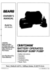
SEARS
OWNER'S
MANUAL
MODELNO.
390.251483
390.251883
CRRFTSMRN°
CAUTION:
Readand Follow
All SafetyRulesand
OperatingInstructions
BeforeFirstUseof
ThisProduct.
Save ThisManual For
FutureReference.
PROFESSIONAL
"HYDROGLASS ''®
SHALLOW WELL JET PUMP
• Safety Instructions
• Installation
• Operation
• Troubleshooting
• Repair Parts
Sears, Roebuck and Co., Hoffman Estates, IL 60179
PRINTED
IN
U.S.A.
U.S.A.
Form No
F642-9906
(Rev, 4/18/01)
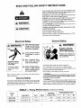
READ AND FOLLOW
SAFETY INSTRUCTIONS!
This is the ,safety alert symbol.
When you see this sTmbol
pump or in this manual, look for one of the following
and be alert to the potemial
for personal
injury:
DANGER
warns about hazards
injury, death or major property
WARNING
warns
about
that will cause serious
damage L_ignored.
hazards
personal
injury., death or major
CAUTION
warns about hazards
sonal
injury
or property
that will
property
that will
damage
manual
Keep
read
and
and on
safety
Replace
Electrical
safety
be capable
only with
motor
Meet
rical
codes
Hazardous voltage.
Can shock, burn, or
cause death.
General
in this
full pump
flow at 75 PSI.
Safety
WARNING I
Hazardous pressure!
Install pressure relief
valve in discharge pipe.
before
power
Release all pressure on
system before working on
any component.
instrucmanual
when
connecting
tor to power
lines.
use padlocks
instructions
are im-
National
ElectCode
and
local
for all wiring.
Follow wiring
tions
in this
Ground pump before
connecting to power
supply.
which
this pump.
nameplate.
Ground
motor
connecting
to
supply.
per-
labels.
of passing
General
Safety
and
serious
condition.
Wire motor for correct
voltage. See "Electrical"
section
of this manual
WARNING
Make workshop_
childproof;
remove starter keys.
instructions
all safety
or damaged
Relief valve must
water
cause
damage if ignored.
or can cause minor
pump.
labels in good
missing
Pump
follow
or can
personal
if ignored.
The label NOTICE
indicates
special
portant
but not related to hazards.
Carefully
on your
signal words
and master
mo-
Periodically
inspect
pump
Wear safety
#asses
at all times
Keep
area
work
properly
Keep
switches;
clean,
all unused
visitors
[_l_ WARNING]
Safety
when
uncluttered
components.
working
on pumps.
and propedy
lighted;
store
tools and equipment.
at a safe distance
Pump
pump
unless
relief
at 75 PSl (517 kPa)
body
from the work
may
valve capable
is installed.
CAUTION_ Motor
Do not allow pump, pressure
tank, piping, or any other system
component
containing
water to freeze. Freezing may damage system, leading to injury or flooding. Allowing pump or system components
t_ freeze will void warranty.
and system
normally
explode
if'used
of passing
operates
areas.
as a booster
full pump
flow
at high temperature
and
will be too hot to touch. It is protected
t_'om heat damage during
operation
by an automatic
internal cut oiff'switch.
Before handling
pump or motor, stop motor and allow it tO cool for 20 minutes.
TABLE I - Pump Performance
Model
(InGallons
Discharge
per
Minute)
Pumping Depth in Feet
No.
Description
Suct.
Disch.
Pressure PSI
5'
10'
15'
20'
390.251483
1/2 HP S.W. Jet
1-1/4"
1"
40
8.2
7.3
5.2
5.0
390.251883
3/4 HP S.W. Jet
1-1/4"
1"
40
10.9
10.4
8.6
7.5
INTRODUCTION
CONTENTS
Safety ..............................................................................................
2
Warranty/Introduction
3
...................................................................
Pump Performance
........................................................................
Major Components
...........................................
3
_ ........................
3-4
Piping .............................................................................................
Electrical
4
.........................................................................................
5
Installation
......................................................................................
6
Operation
.......................................................................................
Maintenance
Helpful
Repair
6
................................................................................
7-8
Hints ..................................................................................
Troubleshooting
We suggest you take a few minutes
to read the instructions
contained in this manual before installing and using your pump. This
will help you obtain the full benefits of the quality and convenience
built into this equipment.
It will also help you avoid any needless
service expense
resulting
from causes beyond our control which
naturally cannot be covered
in our warranty.
8
Guide .................................................................
._9
Parts .............................................................................
10-11
RULES FOR SAFE INSTALLATION
1.
Read
the
Owners
installation
Manual
Instructions
and Instructions
and
Rules
carefully.
could cause
for Safe Operation
Failure to follow
serious
bodily
injury,
and
these
Rules
and/or
prop-
5.
Check
your
your
local electrical
local codes
its full rated
wiring
codes
are not followed,
capacity.
your
before
pump
If in doubt,
contact
installation
meets
installation.
will not work
your
local
6.
pump
4.
test the well water
your
pump
all local
installing
power
source
the pump,
vent leaves and foreign
Be sure your
8.
Complete
pump and piping
below freezing temperature.
plumbing,
always keep the well covered
matter
9.
serious
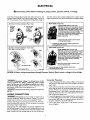
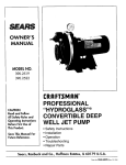
MAJOR
MAJOR COMPONENTS
THEY DO
AND
damage
with
COMPONENTS
the pump
where
for making
all
Impeller
and
turns
Jet
with
rim by centrifugal
pulls in more
motor
force.
water.
shaft,
causing
water
Impeller
rotation
creates
Part of the water
is diverted
to fly out from
a vacuum
back
with
your
pump,
BE CERTAIN
pump
circuit
is properly
grom_ded.
system MUST be protected
against
Failure to do so could cause severe
and frequency
fusing and wiring
Recommended
of t he electrical
circuit
pump
sizing is essential
fusing
and wire
to proper
size data
motor
is in the
/ PIPING
it passes
through
to draw
in more
wells (less than
is enough
sembly
Impeller
Check
and voids the Warranty.
operation.
mallual.
vacuum
tape supplied
to the pump.
electrical
Make sure the line voltage
In shallow
NOTICE: Use Teflon
threaded
connections
pump
IO. The correct
to
WHAT
using.
supply agree with the motor wiring. If motor is dual voltage
type, BE SURE it is wired correctly for your power supply.
to pre-
from falling into the well and con-
tanlinating
the water and/or causing possible
the mechanical
operation
of the pump.
or servicing
before
procedure.
is disconnected.
7.
Power
for purity
for testing
If
and well codes.
While installing
department
Before
damage
Be certain
OPERATION
to
Company.
3.
Always
local health
erty damage.
2.
AND
Volume
The
air volume
and venturi.
This creates
more
water.
20 feet deep),
to pull water
is built into
Air
the nozzle
the vacuum
to the pump.
created
Therefore,
at the
the jet as-
the pump.
Control
its
which
to the jet
Standard
tanks.
control
(AVC)
maintains
the
cushion
of air in
MAJOR COMPONENTS
Pressure
Switch
automatic control.
MODEL NO.
PUMP STARTS AT
PUMP STOPS AT
390.251483
40 PSI
60 PSI
390.251883
40 PSI
60 PSI
from
Well
On well point installations
where
than 25 feet, a check valve should
When
zontal
Never
Pump
to
the horizontal
piping is more
be installed (Figure 3).
the pump is offset more than 25 feet from the well, horipiping should be increased
in size to reduce friction losses.
use offset piping that is smaller than the suction tapping of
the pump.
Tank
Horizontal
The tank serves two functions.
It provides
a reservoir
of water,
some of which can be drawn through the house fixture before the
pump must start. It maintains a cushion of air under pressure.
Two types of tanks are available. Captive Air _ and Standard.
volume control is needed with Captive Air* Tanks.
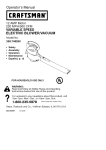
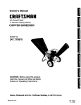
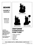
IN THE WELL
lowest level to which the water
(pumping
level) (Figure 1).
Discharge
will drop
while
pump
Piping
t
Pipe
Sizes
251-1/2"
to 50 ft.
a priming
tee and plug must
t
Well
Jets
50 to2"
200 ft.
Sizes
1"
1-1/4"
|
1-1/2"
Up to 25 ft.
25 tolOOft.
T
100 to 600 ft.
is operating
1-1/4"
Well Seal
Plastic Pipe
When using a foot valve,
(Figure 2).
- Shallow
When the pump is some distance
from the house or point of water
use, the discharge pipe size should be increased
to reduce pressure
losses.
should not be too close to the bottom,
or sediment
Before installing foot valve, check to see that it works
be included
Pipe
Plastic
._aValve
NOTE: Check
C_leck
valve useO _f how
zontal p_ping _s 25
or more
Be sure the vertical distance (lift) from the priming
level to pump
is not over 20 feet, if the pump is over well. This will be less if
pump is offset from the well. Both figures are for sea level. The
maximum lift of any pump decreases
with the elevation above sea
level. This decrease
is at the rate of 1 foot per 1000 feet of elevation. For example,
the lift is 17 feet and your elevation is 3000 feet
above sea level. You would then be pumping
17 plus 3, or 20 feet.
This is still satisfactory
for shallow well pumping.
EMERGENCY
Offset
Up1-1/4"
to 25 ft.
No air
A shallow well jet pump can be installed on a dug well, drilled well
or a driven point. SEARS shallow well jet pumps
have a built-in
check valve. In a dug or cased well, a foot valve and strainer should
be installed for easy priming.
It should be 5 to 10 feet below the
The strainer
may clog.it.
freely.
Piping
Horizontal
The pressure switch provides
PIPING
/ PIPING
Steel
Drive
Pipe
1-1/4"
T
5' TOtO'
Pumping Lovel
Foot Valve
1
Drive
Coupling
POWER
Well Point
In some areas and with some installations,
an emergency
power
supply to guard against power failure is a good idea. If you install
an engine-generator
set for emergency
backup
power
for your
pump, supply the generator
set manufacturer
with the nameplate
data from the pump motor. He will then be able to provide a generator of the correct size to power your pump. Also, be sure to add
the load from any other accessories
(such as lights) that may be on
the same circuit.
DUG OR CASED WELL
DRIVEN POINT
FIGURE
FIGURE
3
\
FIGURE
RECOMMENDED
I
FUSING
AND
2
WIRING
DATA
Distance in Feet From Motor to Meter
Motor
Branch
Delayed Fuse
Rating Amps
Oto
50
51 to
101 to
100
200
Wire Size
201 to
300
Pump Model
Horsepower
Volts
Max. Load
Amperes
390.251483
1/2
115/230
10.5/5.2
1_15
14/14
14/14
10/14
8/14
390.251883
3/4
115/230
12.4/6.2
20/15
12/14
12/14
10/14
8/14
4
ELECTRICAL
,_
Disconnect
power
before
working
on pump,
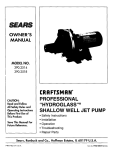
Your Motor Terminal Board (under
the motor end cover)
and
Pressure Switch look like one of those shown
below. Convert to
115 Volts as shown. Do not change motor wiring if line voltage is
pressure
switch,
or wiring.
230 Volts or if you have a single voltage motor.
Connect
power
supply as shown for your type of switch and your supply voltage.
Motor wires connect here.
230 Volt to 115 Volt Conversion, Plug-in Type:
1. Pull plug
straight
out from
terminal
board.
motor,
r wires connecthet:e.
230 Volt: Connect 2 hot wires (black and red)
here and cap the white (neutral) wire. It dons
not matter which wire goes to which screw,
115 Volt: Connect one hot wire (block or red)
to one of these screws (it doesn't matter
which one), Connect the white (neutral)wire
- to the other screw, Cap any remaining
2. Plug in again
with arrow
on plug
pointing to
'115 Volts'.
Clamp the power cable to prevent strain
on the terminal screws.
Connect the green (or bare copper) ground
to the green ground screw.
230 Volt to 115 Volt Conversion,
Move plug to change voltage.
wire
Motor wires connecthere,
-Power supply wires connect here.
230 Volt: Connect 2 hot wires (black and red)
here and cap the white (neutral) wire, It does
not matterwhich wire goes to which screw..
115 Volt: Connect one hot wire (black or red)
to one of these screws (it doesn't matter
which one). Connect the white (neutral) wire
to the other screw, Cap any remaining
blackor red wires,
Plug-in Type:
prevent strain
on the terminal screws,
- Connect the green (or bare copper) ground wire
to the green ground screw.
FIGURE
4: Motor
wiring connections
through
Pressure Switch,
Connection
[AWARNIN_
Hazardous
voltage.
Can
shock,
burn,
or kill.
l.
Connect
ground
wire
before
connecting
power
supply
wires. Use the wire size (including
the ground
wire) speci-
in the wiring chart, if possible, connect the pump to a separate branchcircuit with no other appliances on it.
fied
2.
voltage to line voltage.
Procedure:
the ground
wire first as shown
in Figure 4. The ground
wire must be a solid copper
supply wires.
wire at least as large as the power
There
connection
must be a solid metal
between
the pressure
switch and the motor for motor grounding
protection.
If the
pressure
switch is not connected
to the motor, connect
the
green grotmd screw in the switch to the green ground screw
under the motor end cover. Use a solid copper wire at least as
large as the power supply wires.
LAWARNING] Explosion hazard. Do not ground to a gas supply line.
CONNECTIONS
m
WIRING
Connect
Match motor
31870398
[AWARNINGI Fire
hazard.
Incorrect
voltage
can cause
seriously damage the motor and voids the warranty.
voltage must be within ± 101o of the motor nameplate
a fire or
Connect
the ground wire to a grounded
lead in a service panel,
to a metal underground
water pipe, to a metal well casing at
least ten feet (3M) long, or to a ground electrode
provided
by
the power company
or the hydro authority.
4.
Connect
the power
shown in Figure 4.
The supply
voltage.
NOTICE: Dual-voltage motors are factory wired for 230 volts, if necessary, reconnect
the motor for 115 volts, as shown.
Do not alter
the wiring in single voltage motors.
Install, ground, wire, and maintain
the National Electrical Code (NEC)
(CEC), as applicable,
and with all
apply. Consult your local building
3.
your pump in compliance
with
or the Canadian
Electrical Code
local codes and ordinances
that
inspector
for code information.
5
supply
wires
to the pressure
switch
as
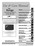
INSTALLATION
/ OPERATION
INSTALLATION
SEARS jet pumps
Figure 5).
should
be used
with
Captive
Air®
Tanks
1.
Wrap 1-1/2 to 2 turns of Teflon tape to all male pipe threads
being attached
to the pump. This will insure leakproof connections. Do not overtighten
threaded
fittings in the plastic pump.
If leaks do occur, remove the fitting, replace
the Teflon tape,
and rewrap with 1-1/2 to 2 turns of Teflon tape and remake the
connection.
2.
independently
Pump,
(See
TO SERVICE
PRIMING PLUG
PRESSURE
t JET
BUIL_I
N
pLASTIC
PLASlqC
support
all piping
connected
to the Hydrogfass
_
pIPE*
PiPE
PUMP
TO
TANK
SIDE VIEW
/
/
\
END VIEW
ta.kfiffingskiL
FIGURE
5
//
For mounting
pump
to tank, purchase
tank fittings
Kit No. 2788.
SEARS Captive Air* Tanks are pre-charged
at the factory. Check the
tank Owners Manual to find if air charge needs adjustment.
Model
390.251483
and Model 390.251883
require 40 pounds
for proper
operation.
FIGURE
The jet pump can also be mounted
on standard horizontal
tanks. A
mounting
kit with an AVC is furnished
with tank. (Figure 6).
Instructions
are also included.
Priming
TO SERVICE
PRIMING
OPERATION
PLUG _._
SHALLOW
/
Pump
run
pump
water may overheat
unit, damaging
sons handling pump.
WELL JET
/BUILT.IN
CHECK
LVEI/4, PLASTIC
the
IA CAUTION j NEVER
_
PRESSURE
SWITCH
__F_L_vBOAU_
7
dry.
Running
pump
seals and possibly
without
burning
per-
pipE *
L_'WARNIN_G_]
NEVERrun pump against closed discharge. To
do so can bod water inside pump,
unit and possibly
scalding persons
o0--T
,_%u. ,%omo_
VO4.UMECONTROL
"Not included
tank flnlnqs
FIGURE
1.
SIDE
v, w
2.
with
kit,
6
Use Teflon
connections
tape supplied
to the pump.
DO NOT USE PIPE JOINT
with
the pump
priming
plug.
Fill pump
with
hazardous
pump.
water.
pressure
Replace
in
priming
plug. If a priming tee and plug have been installed for a long horizontal run, be sure this line is filled and the plug replaced.
(Figure 2, Page 4).
for making
Start the pump. Water will be pumped
in a few minutes;
the
time depending
upon the depth to water and length of hori÷
zontal run. If pump does not prime, check for a possible leak in
the suction line. Reprime.
Check to be sure suction lift - distance from pumping
water level to pump
feet. See °Piping in the Well" on Page 4.
The installation,
operation,
and care of your Hydroglass*
Pump is
very similar to cast iron pumps.
We ask, however,
that you keep
the following
points in mind.
NOTICE:
threaded
Remove
causing
handling
all
COMPOUND.
6
- does not exceed
20
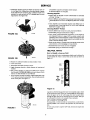
SERVICE
MAINTAINING
YOUR PUMP
B. Loosen
Lubrication
It is not necessary
to lubricate
the pump or its motor•
bearings
are lubricated
for life. The mechanical
shaft
pump
is water
Draining
two screws
and remove
C. If motor has capacitor,
partially
move capacitor
to one side•
lubricated
for
The motor
seal in the
[AWARNINGJ
or is in dana draincock
to vent the
point below
E. Turn
Risk
terminals
D. Hold motor
is to be disconnected
from service,
it must be drained.
The pump has
opened.
Remove
the priming
plug
pressure
tank. Drain all piping to a
canopy.
capacitor
clamp
and
_
pacitor
and selt:adjusting.
Winter
When the pump
ger of freezing,
which must be
pump. Drain the
the freezing line.
e
motor
unscrew
of electrical
with body
shaft with a 7/16"
impeller
shock
Do not touch
ca-
or any metal object.
wrench
counterclockwise
when
on the shaft flats.
facing
it.
3. Remove pump back half from motor by unscrewing
four (4)
nuts. Pry back half off motor by inserting two (2) screwdrivers
between
the back pump half and the motor flange. This will
force rotating portion of seal off shaft. See Figure 8.
To drain an air volume control (AVC), remove the tubing. Turn the
AVC upside down. This will permit any water to drain into tank.
Dis, assembly
and
The Hydroglass*
tenance.
1.
Pump
Disassemble
of Pump
is designed
pump
A Disconnect
B. Open
Assembly
for ease in servicing
as follows:
power.
faucet
to relieve
clamp,
(
pressure.
C. Drain pump by opening draincock.
Remove
tubing from fitting on top of pump.
D. Remove
and main-
Key No. lO, Page
pressure
switch
)
11.
E. Remove
pump base mounting
bolts. Motor assembly
and
back half assembly of pump can be pulled away from front
half.
F. Remove
2.
4750194
O-Rings.
Reassembly
FIGURE
of pump.
A. Clean O-Rings
B. Lubricate
and O_Ring grooves.
O-Rings with petroleum
C. Slide pump
halves
jelly, and place
in grooves•
8
4. Place back half of pump
See Figure 9.
on flat surface
and tap out ceramic
together.
D. Clean inside of clamp. Place clamp around
pump
halves.
Ahemately
tighten clamp screw and tap clamp around outside with plastic mallet. This will insure proper seating of O;
Ring and clamp.
E. Assemble base mounting
ing and close draincock.
F. prime pump
REMOVING
REPLACING
bolts• Connect
pressure
switch
tub
and turn on power.
MOTOR
SHAFT
FOR SERVICE
SEAL
AND
If it is necessary
to remove motor, always replace the shaft seal. We
suggest you purchase
this item, UIO9_A,
and have it on hand for
future use.
NOTICE: The seal consists of two parts, a rotating member and a
ceramic seat. The surfaces of the seal are easily damaged.
Read instructions
carefully.
Remove
motor
1. Disassemble
2. Remove
as follows:
pump
diffuser
per instructions
and impeller
10.
A. Remove
above.
as follows
(Key Nos. 7 and 8, Page
5. Clean seal cavity.
6. Install
,_rews
holding
diffuser.
new seal.
A. Clean polished
B. Wet outer
surface
of ceramic
edge of O-Ring
seat with clean
with detergent
solution.
cloth•
seat.
SERVICE
C. With
finger
pressure
ity. See Figure
If seat will not
polished face
ing purposes.
into cav-
J. Reposition
IOA. Polished face of seat faces inside of pump.
locate properly,
pLAce cardboard
washer over
and use piece of 3/4" standard pipe for pressSee Figure'10B.
press
seat firmly and squarely
K. Remount
Cleaning
capacitor
diffuser
and replace
motor
canopy.
on seal plate.
Inlpeller
1. Follow steps 1A through
of Pump" on Page 7.
1E tinder
2. Remove diffuser and impeller
"Removing
Motor for Service
7.
"Disassembly
and Assembly
from pump per instructions
tinder
and Replacing
Shaft Seal" on Page
3. Clean impeller
and reassemble
impeller
and diffuser per instnictions
under "Removing
Motor for Service and Replacing
Shaft Seal" on pages 7 and 8.
Cleaning
Shallow
To remove
debtis
1. Disassemble
2. Turn
Well
Jet
from venturi
pump
venturi
or nozzle,
per instructions
counterclockwise
proceed
as follows:
on Page 7.
and remove
it. The
nozzle
is
now exposed.
Remove it using a 5/8" hex socket wrench with
extension.
Turn counterclockwise.
If socket wrench is not available, insert an ice pick or similar pointed
nozzle. This will dislodge debris.
tool carefully
into the
3. Flush out the debris by running water through the nozzle
same direction
as the dislodging
tool was inserted.
4. Reinstall
nozzle
and venturi.
5. Reassembh- _ pump
HELPFUL
How
FIGURE
D. Dispose
of cardboard
E. Clean motor
F. Reassemble
washer
and clean
surface
Do not overtighten!
per instructions
on Page 7.
HINTS
to Handle
a Gaseous
In some areas well water
escape
before the water
Figure 12.
4830194
lOB
in the
Well
contains
is used.
gases which must be allowed
This can be done as shown
to
in
of seat.
shaft.
back half of pump
G. Apply detergent
member.
solution
_seto
sudace
to motor.
to inside
diameter
of rotating
seal
H. Slide rotating member on shaft until rubber drive ring hits
shaft shoulder. NOTICE: BE SURE you do not chip or scratch
seal face on shaft shoulder
or seal will leak!
I. Screw impeller on shaft (clockwise)
while holding shaft with
7/16" open end wrench on shaft flats. This will automatically
locate seal in place. See Figure 11.
Not
tO-
valve
Scale
Figure 12
A good way of.delivering
gas-free water is to suspend a pipe, closed
at the bottom
:and open at the top, surrounding
the suction pipe.
Since the gases rise in the well casing, the water sucked
down
through the pipe and into the suction pipe is free of gas. This type
of well must be vented to the outside of any enclosure.
Air
Control
Flowing
special
tem.
478 0194
FIGURE
wells,
problem
In such cases,
air control.
II
8
in Flowing
Wells
or wells
little or no drawdown,
with
in air control
install
a Captive
in the operation
Air® Tank.
could
create
of your water
It does
not require
a
sysany
TROUBLESHOOTING
PROBLEM
POSSIBLE
Motor
1. Disconnect
will not run.
CAUSES
switch
REMEDIES
is off.
1. Be sure switch
2. Fuse is blown.
3. Starting switch is defective.
4. Wires at motor are loose,
disconnected,
or wired incorrectly.
5. Pressure switch contacts
are dirty.
Motor runs hot and
overload kicks off.
cycles
b. Water
too frequently.
level below
1. In new
through:
suction
of pump.
3.Jet orimpeller
is plugged.
4. Check valve or foot valve is stuck
in closedposition.
5. Pipes are frozen.
6. Foot valve and/or strainer
buried in sand or mud.
a. Re-prime according
to instructions.
b. Check all connections
on suction line, air volume
conrail,
and jet.
c. Replace foot valve.
2. In installation
already in use:
a. Check all connections
on suction line, air volume
control, jet and shaft seal.
b. Lower suction line into water and re-prime. If receding
water level in a shallow well operation
exceeds
suction lift, a deep well pump is needed.
3. Clean jet or impeller according
to instructions.
4. Replace check valve or foot valve.
5. Thaw pipes. Bury pipes below
pump house.
6. Raise fm)t valve and/or strainer
are
frost line. Heat pit or
above
capacity (also check
point 3 immediately
above).
Pump pumps water
but does not shut off.
1. Pressure switch is out of adjustment
or contacts are "frozen".
1. Adjust
2. Faucets have been left open.
3. Jet or impeller
is clogged.
4. Water level in well is lower than
estimated.
2. Close
3. Clean jet or impeller.
4. Check for possibility
of using a deep
5. Motor
5. Refer to instructions
on wiring..
Pump cycles
frequently.
too
is wired
contacts.
installation:
1. Water level in well is lower than
estimated.
2. Steel piping (if used) is corroded
limed, caus'mg excess friction.
3. Offset piping is too small in size.
Pump does not
deliver water to full
between
1. Refer to instructions
on wiring.
2. Check with power company.
Install heavier wiring
if wire size is too small. See wiring instructions.
3. See secUon below on too frequent
cycling.
1. Pump in a new installation
did
not pick up prime through:
a. Improper
priming.
b. Air leaks.
c. Leaking foot valve.
2. Pump has lost its prime
a. Air leaks.
is on.
2. Replace fuse.
3. Replace starting switch.
4. Refer to instructions
on wiring.
.
Check and tighten all wiring.
5. Clean by sliding piece of plain paper
1. Motor is wired incorrectly.
2. Voltage is too low.
3. Pump
Motor runs but no
water is delivered.
CHART
or
incorrectly.
well bottom.
1. A deep well jet pump may be needed
(over 20 ft. to water).
2. Replace with plastic pipe where possible,
new steed pipe.
3. Use larger offset piping.
or replace
pressure
otherwise
with
switch.
faucets.
well jet pump.
I. Standard pressure
tank is waterlogged and has no air cushion.
1. Drain talxk to air volume control tapping. Check air
volume control for defects. Check for air leaks at any
2. Pipes leak.
3. Faucets or valves
4. Foot valve leaks.
2.
3.
4.
5.
6.
Check cotmections.
Close faucets or valves.
Replace foot valve.
Adjust or replace pressure
switch.
Disconnect
electrical power
and open faucets until
pressure
is relieved.
Using automobile
tire pressure
check air pressure
in tank at the valve stem located
of tank. ff air pressure
is lower, pump air into tank
outside source, until proper
air pressure
is reached.
Check air valve for leaks, using soapy solution,
and
replace core if necessary.
1.
2.
3.
4.
As soon :ks pump picks up prime, all air will he ejected.
Check suction piping.
Change :installation as described
in manual.
Lower foot valve if possible, otherwise
restrict discharge
side of pump.
connection.
are open.
5. Pressure switch is out of adjustment.
6. Air charge too low in Captive
Tank. Model 390.251483
and Model 390.251883
require
40 pounds for proper operation.
Air spurts
faucets.
from
Leaks at the metal
clamps,
_ WARNING I
Re{_a._all pressurein system
before working on clamp.
1.
2.
3.
4.
Pump is picking up prime.
Leak in suction side of pump.
Well is gaseous.
Intermittent
over-pumping
of well.
1. Loose clamps
not sealed.
or O-Ring
all
gauge,
at top
from
1. Release all system pressure
before working
on clamp.
2. Check that clamp is tight.
3. Tap arotmd clamp with hammer
on a wooden
block.
Retighten
clamp screw.
4. Check ()-Ring for proper seating and/or dirt on
O-Ring or seat.
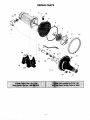
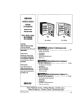
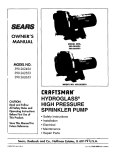
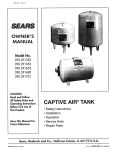
REPAIR PARTS
1/2 HP
Key
No.
.*
Model
390.251483
3/4 HP
Model
Part
390.251883
Description
J218-953C
I**
2
3*
3A
4
5
17351-0009
U78-107PT
6
7
8
9
U109-6A
J105-40PE
J1-39P
U30-542SS
10
11
12
13
14
C19-54SS
U9-201
N32P-66
N34P-19
WC78-41T
L176-47P
U9-399
Motor - 1/2 HP - 115/230V - 60 Cycle
J218-954C
17351-0009
U78-107PT
WC78-41T
L176-47P
U9-399
U109-6A
J105-42PT
J1-39P
U30-542SS
U43-21SS
C19-54SS
15
16
N76-29P
J20-18
N176-28PB
U9-201
N32P-66E
N34P-17
N76-29P
J20-18
N176-28PC
17
18
19
20
21"
22
23
24
25*
25A
26
27
28
29
U37-673P
U111-212T
U9-226
N166-5P
WC78-41T
U212-68T
U30-742SS
C4-42P
U36-37ZP
U43-11ZP
C35-11
2782
U36-112ZP
L43-5C
U37-673P
U111-212T
U9-226
N166÷5P
WC78-41T
U212-68T
U30-742SS
C4-42P
U36-37ZP
U43-11ZP
C35-11
2782
U36-112ZP
L43-5C
Motor - 3/4 HP - 115/230V - 60 Cycle
Water Slinger
Reducer Bushing - 1/2" x 1/8" NPT
Pipe Plug - 1/8" NPT
Tank Body iE_ack Half)
O-Ring - (Sq, Cut) Tank Body - 9-1/2" x 9" x 1/4"
Shaft Seal
Impeller
Diffuser
Screw #8 - 32 x 7/8" (5 Required)
#8 - Star Washer (5 Required)
Clamp - Tank Body
O-Ring - Venturi - 1-3/8" x 1-1/8" x 1/8"
Venturi
Nozzle
Insert
Gasket
Tank Body Assembly - Front Half
Includes Key No. 11, 12, 13, 14, 15, 19, 20 and 23
Switch Tube
90° Hose Barb
O-Ring - Check Valve - 2-1/4" x 2" x 1/8"
Check Valve
Pipe Plug - 1/8" NPT (2 Required)
Draincock- 1/4" NPT
Screw - #10 - 16 x 1-1/8" (4 Required)
Base
Nut - 5/16" - 18 Hex Head (4 Required)
Washer - 5/16" (4 Required)
Motor Pad
Pressure Switch "
Locknut - 1/2"
Connector
*Standard hardware item. May be purchased locally.
**For repair or service to motors, always give the motor model number.
• Not illustrated.
]0
REPAIR PARTS
/
1
2
29
3
3A
28
27
8
9
/
10
11
\
14
26
\
23
19
20
/
7661194
]1
SEARS
OWNER'S
MANUAL
MODELNO.
CRAFTSMAN*
PROFESSIONAL
".HYDROGLASS ''®
SHALLOW WELL
JET PUMP
Forthe repair or replacementpartsyou need
Calf7 am - 7 pm, 7 days a week
390.251483
390.251883
1-800-366-PART
(1-880-366-7278)
Forin-homemajorbrandrepair service
Call24 hours a day,7 daysa week
1-8OO-4-REPAIR
•
The modelnumber of
your Shallow Well Jet
Pumpwill be found on the
pump body.
When requesting service
or ordering parts, always
give the following
information:
•
•
•
•
ProductType
Model Number
Part Number
Part Description
(1-800-473-7247)
Forthe IocaUon_ofa
SearsRepairServiceCenterin yourarea
Call24 hours a day, 7 days a week
1-800-488-1222
Forinformationon purchasinga Sears
MaintenanceAgreementor to inquire
aboutan existingAgreement
call 9 am - 5 pro,Monday-Saturday
_SEARS
1-800-827-6655
SEARS
America's
Repair Specialists
Sears, Roebuck and Co., Hoffman Estates, IL 60179
U.S.A.