1
®
MODEL NUMBER
917.259551
OWNER'SMANUAL
o Assembly
o Operation
o Customer Responsibilities
o Service and Adjustments
o Repair Parts
CAUTION:
Read
and follow
all safety
rules and instructions
before
operating
this equipment.
FOR CONSUMER ASSISTANCE HOT LINE, CALL THIS TOLL FREE NUMBER: 1-800-659-5917
SAFETY RULES
Safe Operation
Practices
for Ride-On
Mowers
&
IMPORTANT:
THIS CUTTING MACHINE IS CAPABLE OF AMPUTATING
HANDS AND FEET AND THROWING
OBJECTS
FAILURE TO OBSERVE THE FOLLOWING SAFETY INSTRUCTIONS
COULD RESULT IN SERIOUS iNJURY OR DEATH
L
•
•
•
•
•
'*
•
o
•
•
•
•
•
•
o
GENERAL
OPERATION
Read, understand, and follow all instructions in the manual
and on the machine before starting
Only allow responsible adults, who are familiar with the
instructions, to operate the machine
Clear the area el objects such as rocks, toys, wire, etc,
which could be picked up and thrown by the blade
Be sure the area is clear of other peopte before mowing Stop
machine if anyone enters the area
Never carry passengers
Do not mow in reverse unless absolutely necessary Always
look down and behind before and whife backing
Be aware of the mower discharge direction and do not point
it at anyone Do not operate the mower without either the
entire grass catcher or the guard in place
Slow down before turning
Never leave a running machine unattended Always turn off
blades, set parking brake, stop engine, and remove keys
before dismounting
Turn off blades when not mowing
Stop engine before removing grass catcher or unclogging
chute.
Mow only in daylight or good artificial light
Do not operate the machine while under the influence of
alcohol or drugs
Watch for traffic when operating near or crossing roadways
Use extra care when loading or unloading the machine into
a trailer or truck
I1o SLOPE
111.CHILDREN
Tragic accidents can occur if the operator is not alert to the
presence of children.
Children are often attracted to the
machine and the mowing activity
Never assume that
children wilt remain where you last saw them
•
Keep children out of the mowing area and under the watchful
care of another responsible adult
•
Be alert and turn machine off if children enter the area
•
Before and when backing, _ook behind and down for small
children
•
Never carry children
They may lalt off and be seriously
injured or interfere with safe machine operation
•
Never allow children to operate the machine
•
Use extra care when approaching blind corners shrubs.
trees, or other obiects that may obscure vision
IV. SERVICE
•
Use extra care in handling gasoline and other fuels Theyare
flammable and vapors are explosive
Use only an approved container
Never remove gas cap or add fuel with fl'_e engine
running Allow engine to cool before refueling Do not
smoke
Never refuel the machine indoors
Never store the machine or fuet container inside where
there is an open flame, such as a water heater
Never run a machine inside a closed area.
Keep nuts and bolts, especially blade attachment bolts, tight
and keep equipment in good condition
Never tamper with safety devices
Check their proper
operation regularly
Keep machine free el grass, leaves, or other debris build-up
Clean oil or fuel spillage
Allow machine to cool beiore
storing
Stop and inspect the equipment il you strike an obiect
Repair, if necessary, before restarting
Never make adjustments or repairs with the engine running
Grass catcher components are subject to wear, damage, and
deterioration, which could expose moving parts or at!ow
objects to be thrown. Frequently check components and
replace with manufacturer's recommended parts, when necessary
Mower blades are sharp and can cut Wrap the blade(s) or
wear gloves, and use extra caution when servicing them
Check brake operation {requently Adiust and service as
required
•
•
OPERATION
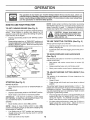
Slopes are a major factor related to loss-of-control
and
tipove r accidents, which can result in severe injury o r death
All slopes require extra caution.
If you cannot back up the
slope or if you feel uneasy on it, do not mow it
DO:
•
Mow up and down siopes, not across
•
Remove obstacles such as rocks, tree limbs, etc
•
Watch for holes, ruts, or bumps
Uneven terrain could
overturn the machine
Tail grass can hide obstacles
•
Use slow speed Choose a tow gear so that you will not have
to stop or shift while on the slope
•
Follow the manufacturer's
recommendations
for wheel
weights or counterweights to improve stability
•
Use extra care with grass catchers or other attachments
These can change the stability of the machine
•
Keep all movement on the slopes slow and gradual Do not
make sudden changes in speed or direction_
•
Avoid starting or stopping on a slope if tires lose traction,
disengage the blades and proceed slowly straight down the
slope
•
•
•
•
•
•
i
i i1,1,, IIH.
ii
ii
i
i
,
i
IH,
i,J,
,i
i
i i
i
Hi
portant
safety precautions.
It means
CAUTION!!!
YOUR
Look for this BECOMEALERT!!I
symbol
to point out
imSAFETY IS INVOLVED.
i iiii,
DO NOT:
•
Do not turn on slopes unless necessary, and then, turn slowly
and gradually downhill, if possible
•
Do not mow near drop-offs, ditches, or embankments
The
mower could suddenly turn over if a wheel is over the edge
of a cliff or ditch, or if an edge caves in
•
Do not mow on wet grass. Reduced traction couid cause
sliding
•
Do not try to stabilize the machine by putting your foot on the
ground.
•
Do not use grass catcher on steep slopes
,,,
iii
H,,,I,
IH
I
III
,
I
H,,,,,
.........................
CAUTioN:
Aiways
di oo.nectspark
p.,g.........
spark plug in order to prevent accidental
wire and place wire where it cannot contact
starting when setting up, transporting,
adjusting or making repairs.
''''L '
IH'll I'll
:_-.
I
II
IIII
I
I
IHHH
A WARNING
The engine exhaust
from this product
contains cliemicals known to the State of California to cause
cancer,
birth
defects,
or other
reproductive
harm°
:_
PRODUCT
917.259551
SERIAL
NUMBER
DATE OF PURCHASE
THEMODELANDSERIALNUMBERSWtLLBEFOUND
ON A PLATE UNDER THE SEAT
YOUSHOULDRECORDBOTHSERIALNUMBERAND
DATE OF PURCHASE AND KEEPIN A SAFE PLACE
FOR FUTURE REFERENCE,
MAINTENANCE
•
°
•
'
GASOUNE
; .25 GALLONS
is available on this prodstore for details.
RESPONSIBRUTIES
Read and observe the safety rules.
Follow a regular schedule in maintaining, caring for and
using your tractor,
Follow the instructions
under "Customer Responsibilities" and "Storage" sections of this owner's manual,
[-IMITED TWOYEAR"WARRANTY
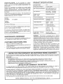
CAPACITY
OIL TYPE (AP[-SF/SG/SH):
SAE 10W30 (above 32°F)
SAE 5W-30 (below 32°F)
OIL CAPACITY:
Wi FILTER:
W/O FILTER:
SPARK PLUG:
(GAP: 040")
CHAMPION
VALVE CLEARANCE:
NOT ADJUSTABLE
40 PINTS
35 PlNTS
RC12YC
GROUND SPEED (MPH):
FORWARD:
REVERSE:
0 -5 5
0-24
TIRE PRESSURE:
FRONT:
REAR:
CHARGING SYSTEM:
3 AMPS BATTERY
5 AMPS HEADLIGHTS
BATTERY:
AMP/HR:
MIN CCA:
CASE SIZE:
BLADE BOLT TORQUE:
AND TYPE:
30-35 FT. LBS.
UNLEADED REGULAR
14 PS1
10 PSi
30
240
UtR
WARNING:
This tractor is equipped with an internal
combustion engine and should not be used on or near any
unimproved forest-covered, brush-covered or grass-covered land unless the engine's exhaust system is equipped
with a spark arrester meeting applicable local or state laws
(if any)_ If a spark arrestor is used, it should be maintained
in effective working order by the operator,
tn the state of California the above is required by law
(Section 4442 of the California Public Resources Code}
Other states may have similar laws Federal taws apply on
federal lands, A spark arrester for the muffler is available
through your nearest Sears Authorized Service Center/
Department (See REPAIR PARTS section of this manual)
AGREEMENT
A Sears Maintenance
Agreement
uct.. Contact your nearest Sears
CUSTOMER
15,5
H
MODEL
,,lUMBER
SPECIFiCAT ONS
HORSEPOWER:
_
CONGRATULATIONS
on your purchase of a Sears
Tractor,, It has been designed, engineered and manufactured to give you the best possible dependability and
performance.
Should you experience any problem you cannot easily
remedy, please contact your nearest Sears Authorized
Service CentedDepartmenL
We have competent, welltrained technicians and the proper tools to service or repair
this tractor
Please read and retain this manuai. The instructions win
enable you to assemble and maintain your tractor properly.
Always observe the "SAFETY RULES".
0N CRAFTSMAN
RIDING EQUIPMENT ............
For two (2) years from the date of purchase, if this Craftsman Riding Equipment is maintained, lubricated and tuned up according
to the instructions in the owner's manual, Sears w{tl repair or replace, free of charge, any parts found to be defective in material or
workmanship.
This Warranty does not cover:
,,
Expendable items which become worn during normal use, such as b_ades, spark plugs, air cleaners, belts, ere
•
Tire replacement or repair caused by punctures from outside objects, such as nails, thorns, stumps, or glass.
•
Repairs necessary because of operator abuse, negligence, improper storage or accident or the failure to maintain the
equipment according to the instructions contained in the owner's manual.
o
Riding equipment used for commercial or rental purposes.
LIMITED 90 DAY WARRANTY
ON BATTERY
For ninety (90) days from date of purchase, if any battery included with this riding equipment proves defective in material or
workmanship and our testing determines the battery will not hold a charge, Sears will replace the battery at no charge
IN-HOME WARRANTY SERVICE ON YOUR CRAFTSMAN RIDING EQUIPMENT IS AVAILABLE AT NO-CHARGE FOR 30
DAYS FROM THE DATE OF PURCHASE
PLEASE CONTACT YOUR NEAREST SERVICE CENTER
AFTER 30 DAYS FROM
THE DATE OF PURCHASE, WARRANTY SERVICE iS AVAILABLE BY TAKING YOUR CRAFTSMAN RIDING EQUIPMENT TO
YOUR NEAREST SEARS SERVICE CENTER, (IN-HOME WARRANTY SERVICE WILL STILL BE AVAILABLE AFTER 30 DAYS
FROM THE DATE OF PURCHASE BUT A STANDARD TRIP CHARGE WILL APPLY)
THIS WARRANTY APPLIES ONLY
WHILE THIS PRODUCT IS 1NTHE UNITED STATES
This Warranty gives you specific legal rights, and you may also have other rights which may vary from stale to state
SEARS,
ROEBUCK
AND CO., D/817 WA, HOFFMAN
ESTATES,
1L 60179
,qu n, ,,,i,,
3
TABLE OF CONTENTS
SAFETY RULES ............................................................
2
PRODUCT SPECIFICATIONS ...................................... 3
CUSTOMER RESPONSIBILITIES ..................... 3, 16-19
WARRANTY ..................................................................
3
TABLE OF CONTENTS ................................................
4
INDEX ............................................................................
4
TRACTOR ACCESSORIES ........................................... 5
ASSEMBLY ................................................................
7-9
OPERATION ............................................................
10-I ,5
MAINTENANCE SCHEDULE ....................................... 16
SERVICE AND ADJUSTMENTS ............................ 20-25
STORAGE .....................................................................
26
TROUBLESHOOTING ............................................
27-28
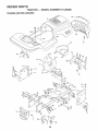
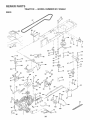
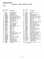
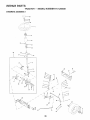
REPAIR PARTS - TRACTOR .................................. 30-47
REPAIR PARTS - ENGINE ..................................... 48-53
PARTS ORDERING/SERVICE .....................BACK PAGE
INDEX
A
E
...........................................
Accessories ...................
: ................ 5
Adjustments:
Brake ..........................................
22
Carburetor .................................... 25
Mower:
Front-To-Back ...........................21
Side-To_Side ...............
21
Throttle Control Cable ................ 24
Air Filter, Engine ...........................
18
Air Screen, Engine ............................. !8
Assembly
7-9
B
........
C
24
29
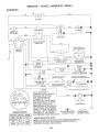
Wiring Diagram ......................
30
Engine:
Air Filter ................................
18
Air Screen .................................
tg
Cooling Fins, Engine ...........
t9
Oil Change
...................
t8
Oil Level
...........................
13, t 8
Oil Type ..................
18
Preparation
..................
13
Repair Parts ......................
48-53
Starting ...........................
14
Storage ...............................
26
F
Filters:
Air .......................................
18
Fuel .................................
19
Fuel:
Type .............................
Storage ..........................
Fuse ...........................
G
Gauge Wheels
..................
13
26
24
8
H
Hoed RemovaVInstailation
L
................... 24
Leveling Mower Deck ........................
Lubrication Chart ......................
21
16
1
I
Interlocks and Relays ...............
Schematic ...............................
M
Maintenance Schedule .............
Mower:
Adjustment, Front-to-Back ......
Adjustment, Side-to-Side .....
Blade Sharpening ..........
Blade Replacement .............
Cutting Height ..................
Installation
Operation
Removal
..............................
..................................
16
21
21
!7
17
12
20
13
20
Cutting Height, Mower
....................
.........................................
...............................
.........................................
...............................
Carburetor Adjustment .......................... 25
Controls, Tractor
Customer Responsibilities .............. 16-19
Engine:
Air Filter ..........................
18
Air Screen, Engine .............
19
Battery
17
Cooling Fins, Engine ............... 19
Engine Oil
19
Fuel Filter ................................ 19
Spark Plugs ...................................19
Tractor:
BJades
17
Lubrication Chart ........................ t6
Maintenance Schedule .......... 16
Tire Care ....................
8,17,23
Oil:
................................
................................
Battery:
Charging ..............................................
7-8
Cleaning
17
Connecting ...............................
7-8
Starting with Weak Battery ..............
23
Storage .......................................
26
Terminals ...................................
17
Belts:
Motion Drive
Removal/Replacement
..............
22
Mower Blade Drive
Removal/Replacement
..... 22
Blade:
Sharpening ................................
17
Replacement ..............................
17
Brake Adjustment .................................. 22
O
Electrical:
12
Mowing Tips ......................................
!5
Muffler ..............................................
19
Spark Arrestor ...............................3,40
Mulcher Plate ............................
g
Cold Weather Conditions ....
Engine ...............................
Storage ..................................
Operation ........................
Operating Mower ........
Options:
Accessories ....................
Spark Arrestor ...........
P
Parking Brake .............
Parts Bag .................................
Parts, Replacement!Repair
Product Specifications
13,18
I8
26
t0-t5
13
5
3,40
11_12
6
30-47
3
R
Repair Parts
...............
30-47
S
Safety Rules ...........
2
Seat ...........................
8
Service and Adjustments
20-25
Brake .......
22
Carburetor ..........
25
Fuse .....................
24
Hood Removal/Installation
24
Motion Drive Beit
Removal/Replacement
22
Mower B_ade Drive Belt
Remova!/Replacement
......
22
Mower Adjustment:
Front-to-Back
.................
2t
Side-to-Side ..................
2I
Mower Installation .......
20
Mower Removal ..............
20
Tire Care
.........
8,17,23
Slope Guide Sheet
55
Spark Plugs ..........
t9
Specifications ........
3
Stading the Engine
13-14
Steering Wheel
......
7,23
Stopping the Tractor
12
Storage ............................
26
T
Throttle Control Cable Adjustment
24
Tires ............
8. t 7.23
Trouble Shooting Chart
27.28
Transaxle Repair Parts
46-47
W
Warranty
.............
Wiring Diagram
Wiring Schematic
4
.........
3
30
29
.n
..i...i..
!
' i.iii1.1.11.1....1111.1
.......
i._.i.:
ACCESSORIES
.
'
..........
.... i.
i .......................
AND ATTACH
,lulnlln
ENTS
ii I,NII ........
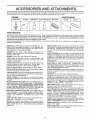
These accessories and attachments were available through most Sears retail outlets and service centers when the tractor was purchased
Most Sears stores can order these items for you when you provide the model number of your tractor
ENGINE
SPARK PLUG
MAINTENANCE
GAS CAN
ENGINE OIL
FUEL STABILIZER
BLADES
BELTS
2
PERFORMANCE
Sears offers a wide variety of attachments that fit your tractor
you. This list was current at the time of publication; however,
may be made in these attachments, or some may no longer
accessories
and attachments
that are available for your
Most of these attachments
attaching and detaching..
Many of these are listed below with brief explanations of how they can help
it may change in future years - more attachments may be added, changes
be available or fit your model Contact your nearest Sears store for the
tractor.
do not require additional hitches or conversion kits (those that do are indicated) and are designed {or easy
AERATOR promotes deep root growth for a healthy lawn Tapered 2 54nch steel spikes mounted on 10-inch diameter discs
puncture holes in soil at close intervaIs to let moisture soak in
Steel weight tray for increased penetration,
SNOW B LAD E for snow removal only. 14-inch high, 48-inch wide
btadeclears42-inch pathwhen angledleft or dght. Raises, lowers
with side lever Adjustable skids; replaceable, reversible scraper
bar (Use with tire chains and wheel weights and/or rear drawbar
weight )
BAGGER lets you collect
grass clippings and leaves for a
healthier, neater !ook_ng lawn. Two Permane,, containers hold
3Q-gallon plastic bags.
BUMPER protects front end of tractor from damage
CARTS make hauling easy
Variety of sizes available, plus
accessories such as side panel kits, too_ caddy, cart cover,
protective mat and dolly
CORING AERATOR takes small plugs out of soil to allow moisture and nutrients to reach grass roots
36-inch swath.. 24
hardened steel coring tips. 150 tb capacity weight tray.
EASY OIL DRAIN VALVE makes eli changes easier, faster
FRONT NOSE ROLLER canters in front of mower deck to reduce
chances of "scalping" on uneven terrain.
GANG HITCH lets you tow 2 or 3 pulFbehind attachments at once,
such as sweepers, dethatchers, aerators (not for use with rollers,
carts or other heavy attachments)_
GAUGE WHEELS on both sides of the mower deck reduce
chances of "scalping" on uneven terrain. For mower decks not so
equipped
MULCH RAKE/DETHATCHER
loosens soil and flips thatch and
matted leaves to lawn sudace for easy pickup Twenty spring tine
teeth. Useful to prepare bare areas forseeding. Available for front
or rear mounting.
HIGH PERFORMANCE
REEL-ACTION
SPRING TINE DETHATCHER covers 36-inch wide path and
tosses thatch into large hopper. Mounts behind tractor.
MULCHING CLOSE-OUT PLATE KIT, once Installed, Iets you
mulch, discharge or bag clippings (bagger optional) without
changing blades For models not equipped as 3-in-1 Convertible
mowers.
See "MOWER" in the Repair Parts section of this
manual.
SNOWTHROWER has 40-inch swath Drum-type auger handles
powdery and wet/heavy snow
Mounts easily with simple pin
arrangement.. Discharge chute adjusts from tractor seat 6-inch
diameter spout discharges snow 10 to 50 feel Lift controlled at
tractor seat. (Use with chains and wheel weights and/or rear
drawbar weight.)
SPRAYERS use 12-volt DC electric motor that connects to lhe
tractor battery or other 12-volt source,
Includes booms for
automatic spraying and hand held wand for spot spraying Wand
has adjustable spray pattern. For applying herbicides, insecticides, fungicides and liquid fertilizers
SPREADER/SEEDERS
make seeding, fertilizing, and weed killing easy. Broadcast spreaders are also useful for granular deicers and sand
SWEEPERS let you collect grass clippings and leaves
TILLER has 5 hp engine and 36-inch swath to prepare seed beds
cult vate and compost garden residue Titler has its own built-in
lift and depth control system and does NOT require a sleeve hitch
Fits any lawn, yard or garden tractor Simply hook up to the traclor
drawbar and go!
Optional
accessories
convert unit for
dethatching, aerating, hilling without tools
TIRE CHAINS are heavy duty; closely spaced extra-large cross
links give smooth ride, outstanding traction
TRACTOR CAB has heavy duty vinyl fabric over tubular steel
frame, ABS plastic top; clear plastic windshield offers 360 degree
visibility Hinged metal doors with catch. Keeps operator warm
and dry. Remove vinyt sides and windshields for use as sun
protector in summer
Optional accessories
include:
tinted/
tempered solid safety glass windshield with hand operated wiper;
12-volt amber caution light for mounting on cab top
VACS for powerful collection of heavy grass clippings and leaves
Optional wand attachment
to pick up debris in hard-to-reach
places VAC/CHIPPER includes a chipper-shredder
WEIGHT BRACKET for drawbar for snow removal applications
Uses (t) 55 lb weight
RAMP TOPS AND FEET let you load and unload tractor from a
pickup truck. Use with 2 x 8 or 2 x 10 lumber
ROLLER for smoother lawn surface,
36-inch wide, 184nch
diameterwater-tightdrumhofdsupto3901bs
ofweight. Rounded
edges prevent harm to tuff Adjustable scraper automatically
cleans drum.
WHEEL WEIGHTS for rear wheels provide needed traction for
snow removal or dozing heavy materials.
5
....
u ,,
i
,,,u,u ..........
_-
CONTENTS
L
U'
UU'U U""UI"
.........................
OF HARDWARE
PACK
I...............
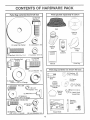
Parts Bag contents
Parts packed
shown fu!l size
separately
in carton
(1) Hex Bolt
3/8q6 x 1
Q
©
Seat
Steering
Wheel
@
(1) Lockwasher
(1) Large Flat Washer
g_
E_
3/8
Steering
Boot
@
(1) Hex Bolt 5t16-18 x 1-1/4
........
j
, i
_t
Video
Cassette
(1) Locknut 5/16-18
i,
(1) Shoulder Bolt
Mulcher
Plate
,,,u
(1) Hex Bolt
t/2-t 3 x t
!
Manuai
Pa_s Bag
5/16-18
Parts bag contents
(1) Lock Washer t/2
T
i i ,,
not shown
x(2)Washers
7/8 x 14 Gauge
3/8
_')
(2) Shoulder
Belts
(1) Washer
....
_'_S
ful! size
i,,Ul
(2) Gauge
, Wheels
17/32 x 1-3/16 x I2 Gauge
;,,,
.....
i .....
,, ,.....
,,,
\
,i,,
Steering Wheel
Adapter
(2) Screws #t0 x 5/8
(2) Lock
Washers
O
#1_
/2_
Wa_d
Nuts
_10
_
I
\
Wheel
Insert
Steering
_/
_)
(2) :Latch Hook
T--I
Assemblys
(2) Washers
16 x 3/4 x t6 Gauge
,u
, u U,l,U,i,
, i_,
Steering
Extension
Shaft
(2) Hex Bolts 114-20 x 3/4
,_k_\
_ik
_Y
(2) Hex Nuts "_.._
114-20
-'_
(2) Washers
(2) Keys
@
Slope Sheet
9/32 x 5_/.8x,,16 Gau,,ge ...._(2_Lock Washers
1/4
--
6
j
,,
, i, i,,,
ASSE
i ,
i,i,,
lU,,,
,......
,u ,,,,,,=
BLY
,,i
....................................
,,i,11,,,
Your new tractor has been assembled at the factory with exception of those parts left unassembled for shipping purposes
To ensure safe and proper operation of your tractor all parts and hardware you assemble must be tightened securely Use
the correct tools as necessary to insure proper tightness..
TOOLS REQUnRED
FOR ASSEMBLY
A socket wrench set will make assembly easier. Standard
wrench sizes are listed
(1) 3/4" Socket w/drive rachet
(2) 7/16" wrenches
(1) PHlfips Screwdriver
(2) 1/2" wrenches
(1) 9/16" wrench
Tire pressure gauge
Utility knife
t
When right or left hand is mentioned in this manual, it
means when you are in the operating position. (seated
behind the steering wheel)
TO REMOVE TRACTOR
UNPACK
o
o
STEERING
FROM CARTON
CARTON
Remove at! accessible loose parts and parts cartons
from carton (See page 6).
Cut, from top to bottom, along lines on all four corners
of carton, and lay panels flat.
Check for any additional loose parts or cartons and
remove.
BEFORE ROLUNGTRACTOR
ATTACH
STEERING
WHEEL
OFF SKID
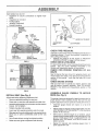
(See Fig. 1)
ASSEMBLE EXTENSION SHAFT AND BOOT
o
Slide extension shaft onto lower steering shaft Align
mounting holes in extension and lower shafts and
install 5/16 hex bolt and Iocknuto Tighten securely.
IMPORTANT: TIGHTEN BOLT AND NUT SECURELY TO
18-22 FT, LBS TORQUE
o Place tabs of steering boot over tab slots in dash and
push down to secure,,
INSTALL STEERING WHEEL
•
Position front wheels of the tractor so they are pointing
straight forward,
o Slide steering wheel adapter onto steering shaft extension,
o Position steering wheel and sleeve assembly so cross
bars are horizontal (left to right) and slide onto adapter.
o Assemble large flat washer, 3/8 lock washer, 3/8 hex
bolt and tighten securely.
o Snap steering wheel insert into center of steering
wheet,
°
Remove protective plastic from tractor hood and grill.
IMPORTANT: CHECK FOR AND REMOVE ANY STAPLES
IN SKID THAT MAY PUNCTU RE TI RES WHERE TRACTOR
IS TO ROLL OFF SKtD
TO ROLL TRACTOR OFF SKiD (See Operation section for location and function of con-
FIG. 1
HOW TO SET UP YOUR TRACTOR
CONNECT
o
Press lift lever plunger and raise attachment lift lever to
its highest position.
Release parking brake by depressing clutch/brake
pedal
o
o
Place gearshift lever in neutral (N) position
Roll tractor backwards off skid°
o
Remove banding holding discharge guard up against
tractor,
(See Figs. 2 and 3)
i
.....................
i_,
n
CAUTION: Do not short battery terminals. Before connecting battery, remove metal bracelets,
wristwatch
bands, rings, etc°
Positive terminal must
first to prevent sparking
tal grounding.
°
•
°
trols)
=
BATTERY
..............
°
o
,,
be connected
from acciden-
Remove cardboard packing from seat pan and lift seat
pan to raised position.
Open battery box door.
Remove terminal protective caps and discard.
If this battery is put into service after month and year
indicated on label (label located between terminals)
charge battery for minimum of one hour at 6-10 amps
First connect RED battery cable to positive (+) terminal
with hex bolt, fiat washer, lock washer and hex nut as
shown. Tighten securely
Connect BLACK grounding cable to negative (-) terminal with remaining hex boit, flat washer, lock washer
and hex nut. Tighten securely.
Close battery box door
ASSEMBLY
Open battery box door for:
o
Inspection for secure connections
ware).
.
Inspection for corrosion
.
Testing battery.
o Jumping (if required),
o Periodic charging
(to tighten hard-
SEAT
SEAT PAN
SHOULDER
BOLT
\
DISCARD
TERMINAL
PROTECTIVE
CAPS
NUT
HEX
LOCK
WASHER
]
FLAT
WASHER
LARGE FLAT WASHER
ADJUSTMENT
BOLT
LOCi( WASHER
FIG. 4
HEX
BOLT
POSITIVE
(RED) CABLE
NEGATIVE
(BLACK) CABLE
FIG, 2
CHECK TIRE PRESSURE
The tires on your tractor were overinflated
shipping purposes Correct tire pressure
best cutting performance
Reduce tire pressure to PSi shown
SPECIFICATIONS" on page 3 of this
CHECK
DECK
at the factory for
is important for
in "PRODUCT
manual.
LEVELNESS
For best cutting results, mower housing shoutd be propedy
leveled
See "TO LEVEL MOWER HOUSING" in fl_e
Service and Adjustments section of this manual
CHECK
BELTS
SEAT
PAN
FOR
PROPER
POSIT_ON
OF ALL
See the figures that are shown for replacing motion and
mower blade drive belts in the Service and Adjustments
section of this manual
Verify that the belts are routed
correctly.
BOX DOOR
CHECK
BRAKE
SYSTEM
After you learn how to operate your tractor, check to see
that the brake is properly adjusted.. See "TO ADJUST
BRAKE" in the Service and Adjustments section of this
manual,
FIG. 3
INSTALL
SEAT (See Fig. 4)
Adjust seat before tightening adjustment bolt,
o Remove cardboard packing on seat pan.
o
•
o
Place seat on seat pan and assemble shoulder bolt,
Assemble adjustment bolt, lock washer and flat washer
loosely. Do not tighten
Tighten shoulder bolt securely
o
Lower seat into operating position and sit on seat.
o
Slide seat until a comfortable position is reached which
allows you to press clutch/brake pedal all the way
down.
o
Get off seat without moving its adjusted position.
o
Raise seat and tighten adjustment bolt securely..
ASSEMBLE
GAUGE
DECK (See Fig. 5)
WHEELS
TO
MOWER
The gauge wheels are designed to keep the mower deck in
proper position when operating mower Be sure tt_ey are
properly adjusted to ensure optimum mower perfolmance
o
Assemble
surface
gauge wheefs with tractor on a fiat level
,,
Adjust mower to desired cutting height (See "TO ADJUST MOWER CUTTING HEIGHT" in the Operation
section of this manual)
o
With mower in desired height of cut position, gauge
wheels should be assembled so they are slightly off the
ground. Install gauge wheel in appropriate hole with
shoulder bolt, 3/8 washer, and 3/8-t6 Iocknut and
tighten securely
o
Repeat for opposite side installing
same adjustment hole
gauge wheel in
ASSEMBLY
..........
,'IM"I
....... H'II......
DEFLECTOR
SHIELD
WHEEL
BRACKET
LATCH
HOOKS
FfG. 5
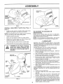
INSTALL
MULCHER
PLATE
(See
Figs.
6
FIGo 7
and 7)
=
Install two latch hooks to mulcher plate using screw,
washer, lock washer, and weJd nut as shown,
TO CONVERT
DISCHARGING
NOTE: Pre-assemble weld nut to iatch hook by insert!ng
weld nut from the top with hook pointing down.
o
o
o
Place front of muicher plate over front of mower deck
opening and slide into place, as shown.
Hook front latch into hole on front of mower deck,
CAUTION: Do not remove discharge
guard from mower. Raise and hold
guard when attaching mulcher plate
and allow it to rest on plate while in
operation.
WELD NUT
FROM
LOCK
WASHER
"'_
HOOK
LOCK
WASHER
OR
,/CHECKLIST
Hook rear latch into hole on back of mower deck.
NUT
BAGGING
Simply remove mulcher plate and store in a safe place,,
Your mower is now ready for discharging or installation of
optional grass catcher accessory
NOTE: It is not necessary to change blades, The muicher
blades are designed for discharging and bagging also
Tighten hardware securely.
Raise and hold deflector shield in upright position.
WELD.
TO
WELD
NUT
WASHER
MULCHER
PLATE
FIG. 6
9
BEFORE YOU OPERATE AND ENJOY YOUR NEW
TRACTOR, WE WISH TO ASSURE THAT YOU RECEt VE
THE BESTPERFORMANCEAND
SATISFACTION FROM
THIS QUALITY PRODUCT
PLEASE REVIEW THE FOLLOWING CHECKLIST
v" All assembly instructions have been completed
,/ No remaining loose parts in carton,
,/ Battery is properly prepared and charged. (Minimum
1 hour at 6 amps)
,/ Seat is adjusted comfortably and tightened securely
,/ All tires are properly inflated. (For shipping purposes,
the tires were overinflated at the factory)
,/ Be sure mower deck is properly leveled side-to-side/
front-to-rear for best cutting results. (Tires must be
properly inflated for leveling),
,/ Check mower and drive belts. Be sure they are routed
properly around pulleys and inside all belt keepers
v" Check wiring.. See that all connections are still secure
and wires are properly clamped.
,/ Before driving tractor, be sure freewheel control is in
drive position.
WHILE LEARNING HOW TO USE YOUR TRA CTOR, PAY
EXTRA A TTENTION TO THE FOLLOWING IMPORTANT
ITEMS:
v" Engine oil is at proper level
v' Fuel tank is filled with fresh, clean, regular unleaded
gasoline.
,/ Become familiar with al! controls - their location and
function, Operate them before you start the engine
v" Be sure brake system is in safe operating condition
¢" it is important to purge the transmission before operating your tractor for the firsttime.. Follow proper starting
and transmission purging instructions (See"TO START
ENG NE ....and PURGE TRANSMISS iO N" in the Operation section of this manual),
|
!
.... i............
ii,
..
'"
_
..
.............
...--......_..._...
i
,. i i..i .....
i.....
OPERATION
:_,
These symbols
..................
may appear
.......
,_,
............
,
on your tractor or in literature supplied with the product,
,,,,
,,
,,
Learn and understand
their meaning
BATTERY
CAUTION OR
WARNING
REVERSE
FORWARD
FAST
SLOW
ENGINE ON
ENGINE OFF
OIL PRESSURE
CLUTCH
LIGHTS ON
LIGHTS OFF
MOWER HEIGHT
DIFFERENTIAL
LOCK
PARKING BRAKE
LOCKED
UNLOCKED
\
FUEL
CHOKE
N H
REVERSE
MOWER LIFT
NEUTRAL
ATTACHMENT
CLUTCH ENGAGED
H IG H
LOW
PARKING BRAKE
ATTACHMENT
CLUTCH DISENGAGED
HYDROSTATIC
DANGER, KEEP HANDS AND FEET AWAY
IGNITION
FREE WHEEL
(Hydro Models onty)
10
.......
ii
,
,
,i,,,
OPERATION
ii
ii1,,
i ....
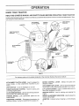
KNOW YOUR TRACTOR
READ THIS OWNER'S
MANUAL
AND SAFETY
RULES
BEFORE
OPERATING
YOUR TRACTOR
Compare the illustrations with your tractor to familiarize yourself with the locations of various controls and adjustments,
this manual for future reference.
ATTACHMENT
CLUTCH LEVER
Save
LIGHT SWITCH
POSITION
IGNITION
SWITCH
AMMETER
,"
.
.
LIFT LEVER
PLUNGER
_.
THROTTLE/CHOKE
CONTROL
ATTACHMENT
LIFT LEVER
HEIGHT
ADJUSTMENT
INDICATOR
CLUTCHIBRAKE
PEDAL
PARKING
BRAKE
MOTION
CONTROL
LEVER
F}:
CONTROL
I"
APPROXo
SPEED
3 MPH
2MPH
1MPH
FIG, 8
Our tractors conform to the safety standards of the American National Standards tnstitute_
MOTION CONTROL
direction of tractor,
ATTACHMENT
CLUTCH LEVER: Used to engage the
mower blades, or other attachments mounted to your
tractor,
LIGHT SWITCH:
LEVER:
Selects the speed and
ATTACHMENT LIFT LEVER: Used to raise and lower the
mower deck or other attachments mounted to your tractor
Turns the headlights on and off
Used for starting and
LIFT LEVER PLUNGER: Used to release attachment lift
lever when changing its position
CLUTCHIBRAKE PEDAL: Used for declutching and braking the tractor and starting the engine.
PARKING BRAKE: Locks clutch/brake pedal into the
brake position,
FREEWHEEL CONTROL - Disengages transmission for
pushing or sfowly towing the tractor with the engine off.
IGNITION SWITCH: tJsed for starting and stopping the
engine
HEIGHT ADJUSTMENT INDICATOR: Used to adjust the
mower cutting height
THROTTLE/CHOKE
CONTROL:
controlling engine speed.
AMMETER:
(-).
11
Indicates battery charging (+) or discharging
i
..................................
OPERATION
T
L,
i
..... ,,,,='_'
1,
_ ,,
The operation of any tractor can result in foreign objects thrown into the eyes, which can
result in severe eye damage. Always wear safety glasses or eye shields while operating your
tractor or performing any adjustments or repairs. We recommend a wide vision safety mask
over the spectacles or standard safety glasses.
NOTE: Under certain conditions when tractor is standing
idle with the engine running, hot engine exhaust gases may
cause "browning" of grass, To eliminate this possibility,
always stop engine when stopping tractor on grass areas
HOW TO USE YOUR TRACTOR
TO SET
PARKING
BRAKE
(See Fig. 9)
Your tractor is equipped With an operator presence sensing
switch. When engine is running, any attempt by the
operator to leave the seat without first setting the parking
brake will shut off the engine
.
Depress clutch/brake pedal into full "BRAKE" position
and hot&
,
Place parking brake lever in "ENGAGED" position and
release pressure from clutch/brake pedal, Pedal should
remain in "BRAKE" position, Make sure parking brake
will hold tractor secure.
ATTACHMENT CLUTCH
"ENGAGED"
POSITION
pletely, as described above, before leavCAUTION:
Always position;
stop tractor
coming
the operator's
to empty
grass catcher, etc.
TO USE THROTTLE
IGNITION
SWITCH
POSITION
Operating engine at less than full throttle reduces the
battery charging rate
°
Full throttle offers the best bagging and mower performance
"DISENGAGED"
POSITION
=
Start tractor with motion control lever in neutral (N)
position
•
Release parking brake and clutch/brake
o
Slowly move motion control lever to desired position
TO ADJUST
Fig. 9)
CLUTCH/BRAKE
PEDAL
"DRIVE" POSITION
(See Fig. 9)
CUTTING
Move attachment clutch lever to "DISENGAGED"
sition.
pedal
HEIGHT
(See
lift lever determines
the
•
Grasp lift lever.
o
Press plunger with thumb and move lever to desired
position
MOWER BLADES -
The cutting height range is approximately 1-1/2 to 4". The
heights are measured from the ground to the blade tip with
the engine not running. These heights are approximate and
may vary depending upon soil conditions, height of grass
and types of grass being mowed.
po-
GROUND DRIVE
°
MOWER
The position of the attachment
cutting height.
FIG. 9
=
AND BACKWARD
The direction and speed of movement is controlled by the
motion control leven
PARKING DRAKE
"ENGAGED"
POSITION
MOTION CONTROL
STOPPING
o
TO MOVE FORWARD
(See Fig. 9)
THROTTLE
"BRAKE"
POSITION
(See Fig. 9)
Always operate engine at full throttle
LEVER
CONTROL
CONTROL
Depress clutch/brake pedal into full "BRAKE" position
o
Move motion control lever to neutral (N) position,
IMPORTANT:
THE MOT!ON CONTROL LEVER DOES
NOT RETURN TO NEUTRAL (N) POSITION WHEN THE
CLUTCH/BRAKE PEDAL tS DEPRESSED
•
The average lawn should be cut to approximately 2-1/2
inches during the cool season and to over 3 inches
during hot months, For healthier and better looking
lawns, mow often and after moderate growth
ENGINE -
o
For best cutting performance, grass over 6 inches in
height should be mowed twice
Make the first cut
relatively high; the second to desired height
o
Move throttle control to slow (,_.)
position.
NOTE; Failure to move throttle control to slow (_)
position and allowing engine to idle before stopping may
cause engine to "backfire"
,
Turn ignition key to "OFF" position and remove key,
Always remove key when leaving tractor to prevent
unauthorized use.
o
Never use choke to stop engine,
12
,
i i,,,,llnluu!
OPERATION
i, n,i,
ilUlU
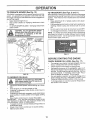
TO OPERATE
.... i
MOWER
(See Fig. 10)
TO TRANSPORT
Your tractor is equipped with an operator presence sensing
switch, Any attempt by the operator to ieave the seat with
the engine running and the attachment clutch engaged will
shut off the engine,
o
Select desired height of cut,
°
Start mower blades by engaging attachment clutch
control.
,
TO STOP MOWER BLADES - disengage attachment
clutch control..
j_,
(See Figs. 8 and 11)
When pushing or towing your tractor, be sure to disengage
transmission by placing freewheel control in freewheeling
position. Free wheel control is located at the rear drawbar
of tractor.
o
Raise attachment lift to highest position with attachment lift control
=
Pull freewheel control knob out and hold in position by
inserting retainer spring into forward hole of control
rod,
o
Do not push or tow tractor at more than two (2) MPH
= To reengage transmission, reverse above procedure
NOTE: To protect hood from damage when transporting
your tractor on a truck or a trailer, be sure hood is closed
and secured to tractor Use an appropriate means of tying
hood to tractor (rope, cord, etc)
CAUTION: Do not operate the mower
without either the entire grass catcher,
on mowers so equipped, or the disc,ha.rge guard,in place.
FIG. 11
BEFORE
CHECK
•
.
•
DISCHARGE
GUARD
FIG. 10
TO OPERATE
o
ON HILLS
I ........
A
CAUTION: Do not driv'e'up or down hills .....
with slopes greater than 15 ° and do not
,_
......
drive across any slope_
..................
o Choose the slowest speed before starting up or down
hills.
= Avoid stopping or changing speed on hills.
If slowing is necessary, move throttle control lever to
slower position°
.
If stopping is absolutely necessary, push clutch/brake
pedal quickly to brake position and engage parking
brake.
•
Move motion control lever to neutral (N) positiono
IMPORTANT:
THE MOTION CONTROL LEVER DOES
NOT RETURN TO NEUTRAL (N) POSITION WHEN THE
CLUTCH/BRAKE PEDAL IS DEPRESSED,
°
To restart movement, slowly release parking brake and
clutch!brake pedal.
•
Slowly move motion control lever to slowest setting.
°
Make all turns slowly
o
13
STARTING THE ENGINE
ENGINE
OIL LEVEL
(See Fig. 17)
The engine in you r tractor has been shipped, from the
factory, already filled with summer weight oil.
Check engine oil with tractor on level ground
Unthread and remove oil fill cap/dipstick; wipe oit off
Reinsert the dipstick into the tube and rest oil fill cap on
the tube. Do not thread the cap onto the tube, Remove
and read oil level. If necessary, add oil until "FULL"
mark on dipstick is reached.. Do not overfill.
For cold weather operation you should change oil for
easier starting (See "OIL VISCOSITY CHART" in the
Customer Responsibilities section of this manual)
To change engine oil, see the Customer Responsibilities section in this manual.
..
:
i..
. .
.
t...4_....
...... ,. .i .i.¸ ..i..
•
........
...............................
OPERATNON
........
,,,rlJ
....
i u..nl ii,
_"_
-::=:="•'""1 ¸
'
i lUMUUl
ADD GASOLINE
COLD WEATHER STARTING ( 50 ° F and below)
•
.
Fill fuel tank_ Use fresh, clean, regular unleaded
gasoline with a minimum of 87 octane (Use of leaded
gasoline will increase carbon and lead oxide deposits
and reduce va{ve life) Do not mix oil with gasoline.
Purchase fuel in quantities that can be used within 30
days to assure fuel freshness.
IMPORTANT: WHEN OPERATING iN TEMPERATURES
BELOW 32°F(0°C), USE FRESH, CLEAN WINTER GRADE
GASOLINE TO HELP INSURE GOOD COLD WEATHER
STARTING
WARNING:
Experience indicates that alcohol blended
fuels (called gasohol or using ethanol or methanol) can
attract moisture which leads to separation and formation of
acids during storage. Acidic gas can damage the fuel
system of an engine while in storage. To avoid engine
problems, the fuel system should be emptied before storage of 30 days or longer. Drain the gas tank, start the
engine and let it run until the fuel lines and carburetor are
empty. Use fresh fuel next season. See Storage Instructions for additional information.
Never use engine or
carburetor cleaner products in the fuel tank or permanent
damage may occur.
.
,
TO START
, .......
ENGINE
n
o
_W
Place motion control lever in neutral (N) position.
Move attachment clutch to "DISENGAGED" position
o
Move throttle control to choke (N)
position
•
Note: Before starting, read the warm and cold starting
procedures below
o
o
r enga_
hile the engine is run-
I
To ensure proper operation and performance, it is recommended that the transmission be purged before operating
tractor for the first time. This procedure will remove any
trapped air inside the transmission which may have developed dudng shipping of your tractor.
IMPORTANT; SHOULD YOUR TRANSMISSION REQUIRE
REMOVAL FOR SERVICE OR REPLACEMENT,
tT
SHOULD BE PURGED AFTER REINSTALLATION
BEFORE OPERATING THE TRACTOR
Be sure freewheel control is in the transmission engaged position
Sit on seat in operating position, depress clutchtbrake
pedal and set parking brake
o
Insert key into ignition and turn key clockwise to"START"
position and release key as soon as engine starts. Do
not run starter continuously for more than fifteen seconds per minute° If the engine does not start after
several attempts, move throttle control to fast (,_)
position, wait a few minutes and try again If engine stiN
does not start, move the throttle control back to the
choke (N) position and retry.
WARM WEATHER
Before driving the unit in cold weather, the transmission shoutd be warmed up as follows:
o Be sure the tractor is on level ground
•
Place the motion control lever in neutral.
Release the parking brake and let the clutch/brake
slowly return to operating position
o Allow one minute for transmission to warm up
This can be done during the engine warm up
period
The attachments can also be used during the engine
warm-up period afterthe transmission has been warmed
up.
PURGE TRANSMISSION
(See Fig. 9)
o
o
o
WARM UP
i, ,u,,i i,:1
When starting the engine for the first time or if the engine
has run out of fuel, it will take extra cranking time to move
fuel from the tank to the engine
o
TRANSMISSION
NOTE; If at a high altitude (above 3000 feet) or in cold
temperatures (below 32 F) the carburetor fuel mixture may
need to be adjusted for best engine performance, See "TO
ADJUST CARBURETOR" in the Service and Adjustments
section of this manual.
filler neck. Do notoverfilL Wipe off any
CAUTION:
spilled
oil orFill
fuel.to Do
bottom
not store,
of gas
spilltank
or
use gasoline near an open flame.
-
When engine starts, allow engine to run with the throttle
control in the choke ( \ ) position until the engine runs
roughly, then move thrott e contro to fast (,_) pos tion
This may require an engine warm-up period from
several seconds to several minutes, depending on the
temperature.
HYDROSTATIC
o
I',1
STARTING (50 ° F and above)
When engine starts, move the throttle controlto the fast
(,t_) position.
The attachments and ground drive can now be used. tf
the engine does not accept the load, restart the engine
and allow it to warm up for one minute using the choke
as described above,
14
Place tractor safely on level surface with engine off and
parking brake set.
Disengage transmission by placing freewheel control
in freewheeling position (See "TO TRANSPORT" in
this section of manual).
o
Sitting in the tractor seat, start engine, After the engine
is running, move throttle control to slow (,_,) position,
With motion control lever in neutral (N) position, sfowly
disengage clutch/brake pedal,
•
Move motion control lever to ful! forward position and
hold for five (5) seconds
Move lever to full reverse
position and hold for five (5) seconds
Repeat this
procedure three (3) times
.... irl,,
u
....
ii
i
UUlll,lll,
llll ......................
ii
OPERATUO
...............
i,,
,UllllllUU, ,,u
NOTE" During this procedure there will be no movement of
drive wheels. The air is being removed from hydraulic drive
system,.
.
Move motion control lever to neutral (N) position., Shutoff engine and set parking brake
o
Engage transmission by placing freewheel control in
driving position (See "TO TRANSPORT" in this section
of manual),
-
Sitting in the tractor seat, start engine. After the engine
is running, move throttle control to half (1/2) speed,
With motion control lever in neutral (N) position, slowly
disengage clutch/brake pedal,
o
.
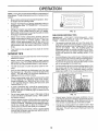
MULCHING
Mower should be properly teveied for best mowing
performance. See "TO LEVEL MOWER HOUSING" in
the Service and Adjustments section of this manual,,
The left hand side of mower should be used for trimruing
o
•
Drive so that clippings are discharged onto the area
that has been cuL Have the cut area to the right of the
tractor This will result in a more even distribution of
clippings and more uniform cutting.
°
When mowing large areas, start by turning to the right
so that clippings wilt discharge away from shrubs,
fences, driveways, etc, After one or two rounds, mow
in the opposite direction making left hand turns unti!
finished (See Fig 12),
.
if grass is extremely tall, it should be mowed twice to
reduce load and possible fire hazard from dried clippings, Make first cut relatively high; the second to the
desired heighL
°
Do not mow grass when it is wet, Wet grass will plug
mower and leave undesirable clumps° Allow grass to
dry before mowing,
•
Always operate engine at full throttle when mowing to
assure better mowing performance and proper discharge of material, Regulate ground speed by selecting a low enough gear to give the mower cutting
performance as well as the quality of cut desired.
.
i
i
MOWING
TIPS
IMPORTANT:
FOR BEST PERFORMANCE,
KEEP
MOWER HOUSING FREE OF BUILT-UP GRASS AND
TRASH CLEAN AFTER EACH USE
.
The special mulching blade will recut the grass clippings many times and reduce them in size so that as
they fall onto the lawn they witl disperse into the grass
and not be noticed, Also, the mulched grass will
biodegrade quickly to provide nutrients for the lawn.
Always mulch with your highest engine (blade) speed
as this will provide the best recutting action of the
btades,
o
Avoid cutting your lawn when it is wet Wet grass tends
to form clumps and interferes with the mulching action
The best time to mow your lawn is the early afternoon
At this time the grass has dried and the newly cut area
will not be exposed to the direct sun.
,,
For best results, adjust the mower cutting height so that
the mower cuts off only the top one-third of the grass
blades (See Fig. t3) For extremely heavy mulching,
reduce your width of cut on each pass and mow slowly
MOWING TriPS
o
iii
FIG. 12
Your tractor is now purged and now ready for normal
operation,
Tire chains cannot be used when the mower housing is
attached to tractor_
,,
f
Slowly move motion control lever forward, after the
tractor moves approximately five (5) feet, slowly move
motion control lever to reverse position
After the
tractor moves approximately five (5) feet return the
motion control ]everto the neutral (N) position. Repeat
this procedure with the motion control lever three (3)
times
•
,
MAX 113
tit
I#1
I1_!
rt,l,_L,
=.t,
=.,
FIG. 13
When operating attachments, select a ground speed
that will suit the terrain and give best performance of
the attachment being used,
'15
o
Certain types of grass and grass conditions may re_
quire that an area be mulched a second time to corn _
pletely hide the clippings, When doing a second cut,
mow across or perpendicular to the first cut path,
o
Change your cutting pattern from week to week Mow
north to south one week then change to east to west the
next week, This will help prevent matting and graining
of the lawn
OUSTOI IJER RESPONSBIB UTHES
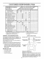
iviAINTENANCE
SCHEDULE
/_
FILL IN DATES
AS YOU COMPLETE
REGULAR SERVICE
Check
T
i
Brake Operation
_#/
Check Tire Pressure
_
Check for Loose Fasteners
_'
Check
_/_"
._0_"
__TSERVICE
Sharpen/Replace
Mower Blades
, Lubrication Chart
T
./._e_'_,o_d
/_,,,_/___
/_.,._/_"_?,'_"a/_,_O9,__._"
Battery LeveltRecharge
_'
DATES
......
l
V7
._
_
_
_#'
_/'4
I_
___
6#t
_e
..........
v'
Clean Battery and Terminals
Check Transaxte Cooling
/
v'
e,'
Adjust Blade Belt(s) Tension
Adjust Motion Drive Belt(s) Tension
Check
Engine Oil Level
Change Engine
E
Oft
Clean Air Filter
N ! Clean Air Screen
G i Inspect
I
Replace
NE
12 3 4 -
I
....
Muffler/Spark
I
Arrester
'
l
OIl Filter (lf equipped)
Clean Engine Cooling
Iv'2
tvSi
l
!
Fins
Replace
Spark Plug
Replace
Atr Filter Paper Cartridge
Replace
Fuet Filter
2
v'
Change mere oilen when operating under a heavy load or in high ambient temperatures
Service more ellen when operagng indirty or dusty conditions
t! equipped with oil tilter, change ell eve N 50 hours
Replace blades mote otlen when mowing in sandy soil
GENERAL
.....
5 - if equipped
6 ,. Not
RECOIVlMENDATIONS
with
required
7 - Tighten
ad}ustab_e
il eq_Jipped
front axle pivot
system
with
CHART
(_! SPINDLE ZER K ___.._
SPIN DLE ZER K (_)
(_) FRONT WHEEL_I_
Some adjustments will need to be made periodically to
properly maintain your tractor
BEARING
battery
maximum
De nol overtighten
LUBRICATION
The warranty on this tractor does not cover items that have
been subjected to operator abuse or negligence,
To
receive full value from the warranty, operate r must maintain
tractor as instructed in this manual.
maintenance-free
bo!l lo 35 It -tbs
ZERK
............. ]/T'_
_
I
_
_
FRONT WHEEL (_
BEARING
AII adjustments in the Service and Adjustments section of
this manual should be checked at least once each season,
ENGINE (_)
Once a year you should replace the spark plug, clean
or replace air filteq and check blades and belts for
wear, A new spark plug and clean air filter assure
proper air-fuel mixture and help your engine run better
and fast longer
BEFORE
ZERK
®
CLUTCH
PIVOT(S)
EACH USE
o
Check engine oil level.
o
Check brake operation
(_) SAE 30 OR 10W30 MOTOR OIL
o
•
Check tire pressure.
Check for loose fasteners.
(_ GENERAL
PURPOSE GREASE
(_ REFER TO CUSTOMER
RESPONSIBILtTIES
"ENGINE"
SECTION
IMPORTANT:
DO NOT OIL OR GREASE
THE PIVOT POINTS
WHICH HAVE SPECIAL NYLON BEARINGS
VISCOUS
LUBRICANTS WILL ATTRACT
DUST AND DIRT THAT WiLL SHORTEN
THE LIFE OF THE SELF-LUBRICATING
BEARINGS,
1F YOU
FEEL THEY MUST BE LUBRICATED.
USE ONLY A DRY. POWDERED GRAPHITE
TYPE LUBRICANT
SPARINGLY
16
=,==l
==,,=
,,==l,== ,,
......
,,,,= i,=,
BRAKE
safety rules when pedorming
any mainte-
OPERATION
If tractor requires more than six (6) feet stopping distance
at high speed in highest gear, then brake must be adjusted,,
(See 'q'O ADJUST BRAKE" in the Service and Adjustments section of this manual)°
TIRES
o
Maintain proper air pressure in all tires (See "PRODUCT SPECIFICATIONS
on pag 3 of this manual)
=
Keep tires free of gasoline, oil, or insect control chemicals which can harm rubber.
o Avoid stumps, stones, deep ruts, sharp objects and
other hazards that may cause tire damage.
NOTE: To seal tire punctures and prevent flat tires due to
stow leaks, tire sealant may be purchased from your local
parts dealer. Tire sealant also prevents tire dry rot and
corrosion.
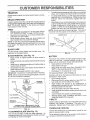
BLADE
•
,
o
o
The blade can be sharpened with a file or on a grinding
wheel Do not attempt to sharpen while on the mower
,
To check blade balance, you will need a 5/8" diameter
steel bolt, pin, or a cone balancer. (When using a cone
bafancer, follow the instructions supplied with balance r)..
o
Slide blade on to an unthreaded portion of the steel bolt
or pin and hold the bolt or pin parallel with the ground,
If blade is balanced, it should remain in a horizontal
position_ If either end of the blade moves downward,
sharpen the heavy end until the blade is balanced
NOTE: Do not use a nail for balancing blade. The lobes of
the center hole may appear to be centered, but are not
CENTER HOLE
5_"BOLT
BLADE
OR PtN
CARE
For best results mower blades must be kept sharp
place bent or damaged blades.
BLADE
.==l H,,
o
TRACTOR
Aiways observe
nance.
=.... ,,.,!-H
REMOVAL
Re-
(See Fig, 14)
BATTERY
Raise mower to highest position to allow access to
blades.
Remove hex bolt, lock washer and fiat washer secudng
blade.
Install new or resharpened blade with trailing edge up
towards deck as shown.
Reassemble hex bolt, lock washer and flat washer in
exact order as shown
•
Tighten bolt securely (30-35 Ft. Lbs.. torque).
IMPORTANT: BLADE BOLT tS GRADE 8 HEAT TREATED.
NOTE: We do not recommend sharpening blade- but if you
do, be sure the blade is balanced.
BLADE
MANDREL
ASSEMBLY
TRAILING
LOCK WASHER_.
FLAT WASHER_
HEXBOLT
(GRADE8)*
!
"A GRADE 8 HEAT TREATED BOLT CAN BE
IDENTIFIED BY SIX LINES ON THE BOLT HEAD.
FIG. 14
TO SHARPEN
BLADE
FIG. 15
(See Fig. 15)
EDGE
Your tractor has a battery charging system which is sufficient for normal use However, periodic charging of the
battery with an automotive charger will extend its life
•
Keep battery and terminals clean
.
Keep battery bolts tight_
o
Keep small vent holes open (See "CONNECT BATTERY" in the Assembly section of this manual)
.
Recharge at 6-10 amperes for I hour.
TO CLEAN BATTERY AND TERMINALS
Corrosion and dirt on the battery and terminals can cause
the battery to "leak" power
=
Open battery box door
Disconnect BLACK battery cable first then RED battory cable and remove battery from tractor
•
Wash battery with solution of four tablespoons of
baking soda to one gallon of water. Be careful not to get
the soda solution into the cells.
o
Rinse the battery with plain water and dry.
o
Clean terminals and battery cable ends with wire brush
until bright.
•
Coat terminals with grease or petroleum jelly
o Reinstall battery (See "CONNECT BATTERY" in the
Assembly section of this manual)
V-BELTS
Check V-belts for deterioration and wear after 100 hours of
operation and replace if necessary_ The belts are not
adjustable Replace belts if they begin to slip from wear
TRANSAXLE
COOLING
The fan and cooling fins of transmission
clean to assure proper cooling.
should be kept
Care should be taken to keep the blade balanced. An
Do not attempt to clean fan or transmission while engine is
unbalanced blade wilt cause excessive vibration and evenrunning or while the transmission is hot
tual damage to mower and engine.
17
OUSTO#ER
•
o
RESPONSIB L[TmES
Inspect cooling fan to be sure fan blades are intact and
clean.
Inspect cooling fins for dirt, grass clippings and other
materials, To prevent damage to seals, do not use
compressed air or high pressure sprayer to clean
cooling fins
TRANSAXLE
PUMP
COVER
AIR CLEANER
KNOB
WING NUT
COVER
FOAM
PRE-CLEANER
FLUID
The transaxle was sealed at the factory and fluid maintenance is not required for the life of the transaxle. Should the
transaxle ever leak or require servicing, contact your nearest authorized service center/department.
ENGINE
LUBRICATION
AIR CLEANER
BASE
PAPER CARTRIDGE
Onfy use high quality detergent oil rated with API service
classification SF, SG, or SH.. Select the oil's SAE viscosity
grade according to your expected operating temperature,
, OIL FILL
CAP/DIPSTICK
AIR
SCREEN
SAE V1SCOSITYGRADES
°!
"2°_
°c .30°
30°
O°
-2o°
TEMPERATURE
-lo.
a2" 40"
0"
RANGE ANTICIPATED
60"
1'o
°
e0°
20'
too
°
30'
4o°
BEFORE NEXT OIL CHANGE
FIG. 16
Change the oil after the first two hours of operation and
every 50 hours thereafter or at least once a year if the
tractor is not used for 50 hours in one year.
OIL DRAIN
PLUG
Check the crankcase oil level before starting the engine
and after each eight (8) hours of operation. Tighten oil fill
cap/dipstick securely each time you check the oil level..
FIG. 17
AIR FILTER
TO CHANGE ENGINE OIL (See Fig 17)
(See Fig. 17)
°
Be sure tractor is on level surface.
Your engine will not run properly using a dirty air filter
Clean the foam pre*cleaner after every 25 hours of operation or every season, Service paper cartridge every 100
hours of operation or every season, whichever occurs first
•
°
Oil will drain more freely when warm.
Catch oil in a suitable container.
Service air cleaner more often under dusty conditions
o Remove knob and cover
•
Remove oil fill cap/dipstick. Be careful not to allow dirt
to enter the engine when changing oil
Remove wing nut and air cleaner from base
TO SERVICE PRE-CLEANER
.
Remove drain plug.
•
Slide foam pre-cleaner off cartridge
o
After oil has drained cOmpletely, replace oil drain plug
and tighten securely.
o
Wash it in liquid detergent and water,
o
Refill engine with oil through oil fill dipstick tube. Pour
slowly. Do not overfill, For approximate capacity see
'PRODUCT SPECIFICATIONS"
on page 3 of this
manual
o
Squeeze it dry in a clean cloth. Allow it to dry
.
Use gauge on oil fill cap/dipstick for checking level,
Insert dipstick into the tube and rest the oil fill cap on the
tube. Do not thread the cap onto the tube when taking
reading. Keep oil at"FULL" line on dipstick. Tighten
cap onto the tube securely when finished,
Determine temperature range expected before oil change
All oil must meet API service classification SF, SG, or SH
o
Saturate it in engine oil Wrap it in clean, absorbent
cloth and squeeze to remove excess oil.
TO SERVICE CARTRIDGE
o
Replace a dirty, bent, or damaged cartridge
NOTE: Do not wash the papercartridge
air, as this will damage the cartridge
18
or use pressurized
.
Reinstall the pre-cleaner (cleaned and oiled) over the
paper cartridge.
•
Reassemble air cleaner, wing nut, cover and tighten
knob securely
i
i
,
CUSTOMER
........
CLEAN
AIR SCREEN
i
ii I,,HI
II
II .........................
__
RESPONS!BULmTIES
:
= ................
(See Fig. 17)
i,i..................
i
......
MUFFLER
Air screen must be kept free of dirt and chaff to prevent
engine damage from overheating, Clean with a wire brush
or compressed air to remove dirt and stubborn dried gum
inspect and replace corroded muffler and spark arrester (if
equipped) as it could create a fire hazard and/or damage
fibers°
SPARK
CLEAN
AiR INTAKE/COOLING
PLUGS
Replace spark plugs at the beginning of each mowing
season or after every 100 hours of operation, whichever
occurs first. Spark plug type and gap setting are shown in
"PRODUCT SPECIFICATIONS" on page 3 of this manual.
AREAS
To insure proper cooling, make sure the grass screen,
cooling fins, and other external surfaces of the engine are
kept clean at all times.
IN-LINE
FUEL FILTER
(See Fig. 19)
Every 100 hours of operation (more often under extremely
dusty, dirty conditions), remove the blower housing and
other cooling shrouds. Clean the cooling fins and external
surfaces as necessary. Make sure the cooling shrouds are
reinstalled..
The fuel filter should be replaced once each season., if fuel
filter becomes clogged, obstructing fuel flow to carburetor,
replacement is required
o
NOTE: Operating the engine with a blocked grass screen,
dirty or plugged cooling fins, and/or cooling shrouds removed will cause engine damage due to overheating
With engine coot, remove filter and plug fuel line
sections
o
Place new fuel filter in position in fuel line with arrow
pointing towards carburetor.
o
Be sure there are no fuel line leaks and clamps are
properly positioned
o
Immediately wipe up any spilled gasoline
ENGINE
OIL FILTER
(See Fig. 18)
Replace the engine oil filter every season or every other oil
change if the tractor is used more than 100 hours in one
year
o
Drain oil from engine crankcase (See "TO CHANGE
ENGINE O1U' in this section of this manual, through
step remove drain plug).
o
Remove oil filter and wipe off filter adapter.
•
Apply a thin coating of new engine oil to the rubber
gasket on replacement oil filter.
o
Install replacement oil filter on filter adapter. Turn oil
filter clockwise until rubber gasket contacts the filter
adapter, then tighten filter an additional 1/2 turn
o
o
CLAMP
CLAMP
FUEL
/
FILTER'
FIG. 19
Fill crankcase with new oil (See "TO CHANGE ENGINE OIL" in this section of this manual). For approximate capacity see "PRODUCT SPECIFICATIONS" on
page 3 of this manual
CLEANING
Start the engine and check for oil leaks. Correct any
leaks before placing engine into ful! operation..
o
Clean engine, battery, seat, finish, etc. of all foreign
matter.
o
Keep finished surfaces and wheels free of all gasoline,
oi!, etc.
o
Protect painted surfaces with automotive type wax.
We do not recommend using a garden hose to clean your
tractor unless the electrical system, muffler, air filter and
carburetor are covered to keep water out Water in engine
can result in a shortened engine life
OIL FILTER
- L_.,.,.J
FIG, 18
t9
SERVICE AND ADJUSTMENTS
i
CAUTION:
o
o
o
o
o
o
BEFORE PERFORMING
ANY SERVICE OR ADJUSTMENTS:
I
Place motion control lever in neutral (N) position.
Depress
clutchtbrake
pedal
fully and set parking
brake.
Place
attachment
clutch
in "DISENGAGED"
position,
Turn ignition key "OFF" and remove key,
Make sure the blades and all moving parts have completely stopped.
Disconnect spark plug wire from spark plug and place wire where it cannot come in contact
with plug.
,
', .....
,,,,
i,,,u,,
, ............
........
I lUlH
TRACTOR
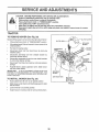
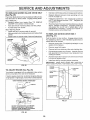
TO REMOVE
MOWER
(See Fig. 20)
Mowerwi]l be easier to remove from the right side of tractor
o
•
LEVER
Place attachment dutch in "DISENGAGED" position,
Move attachment lift tever forward to tower mower to its
lowest position
RETAINER
SPRING
Roll belt off engine pulley,
PULLEY
o
Disconnect c{utch rod from clutch lever by removklg
retainer spring
°
Disconnect antFsway bar from chassis bracket by
removing retainer spring
°
Disconnect suspension arms from rear deck brackets
by removing retainer springs.
•
Disconnect front links from deck by removing retainer
springs_
o
Raise lift lever to raise suspension arms Slide mower
out from under tractor
RETAINER
SPRINGS
BOTH SIDES
IMPORTANT:
IF AN ATTACHMENT OTHER THAN THE
MOWER IS TO BE MOUNTED TO THE TRACTOR, THE
R.H. AND L.H, SUSPENSION ARMS MUST BE REMOVED
FROM TRACTOR
RETAINER
SPRING
ANTI-SWAY
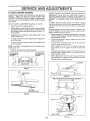
TO INSTALL
MOWER
(See Fig. 20)
o
Raise attachment lift lever to its highest position
o
Slide mower under tractor with discharge guard to right
side of tractor,
°
o
Lower lift lever to its lowest position,
Install mower in reverse order of removal instructions
BAR
RETAINER
SPRINGS
(BOTH SIDES)
FIG, 20
2O
!
.................
SERVICE
AN
ADJUSTMENTS
'
TO LEVEL
MOWER
HOUSING
ADJUSTMENT
Raise mower to its highest position
=
At the midpoint of both sides of mower, measure height
from bottom edge of mower to ground. Distance"A" on
both sides of mower should be the same or within t/4"
of each other.
o
if adjustment is necessary, make adjustment on one
side of mower only.
o
To raise one side of mower, tighten lift link adjustment
nut on that side.
o
To tower one side of mower, loosen lift link adjustment
nut on that side
NOTE: Each full turn of adjustment nut will change mower
height about 1/8"
o
Recheck measurements
after adjusting.
BOTTOM EDGE
OF MOWER TO
GROUND
1,1,
,,N 1,,,,,,,,,,1
=l,=
,,1
.......................
To obtain the best cutting results, the mower housing
should be adjusted so that the front is approximately 1/8" to
1/2" lower than the rear when the mower is in its highest
position..
Check adiustment on right side of tractor Measure distance"D" directly in front and behind the mandrel at bottom
edge of mower housing as shown.
.
Before making any necessary adjustments, check that
both front links are equal in length. Both links should be
approximately t 0-3/8"
o If links are not equal in length, adjust one link to same
length as other link.
o To lower front of mower loosen nut "E" on both front
links an equal number el turns
•
When distance "D" is 1/8" to 1/2" lower at front than
rear, tighten nuts "F" against trunnion on both front
links
o To raise front of mower, loosen nut"F" from trunnion on
both front links. Tighten nut "E" on both front links an
equal number of turns..
o When distance "D" is 1/8" to 1/2" lower at front than
rear, tighten nut"F" against trunnion on both front links
o
Recheck side-to-side adjustment.
(See Figs. 21 and 22)
=
i
FRONT-TO-BACK ADJUSTMENT (See Figs. 23 and 24)
IMPORTANT: DECK MUST BE LEVEL SIDE-TO-SIDE IF
THE FOLLOWING FRONT*TO-BACK ADJUSTMENT IS
NECESSARY, BE SURE TO ADJUST BOTH FRONT LINKS
EQUALLY SO MOWER WILL STAY LEVEL SIDE-TO.
SIDE.
Adjust the mower while tractor is parked on level ground or
driveway,
Make sure tires are properly inflated (See
"PRODUCT SPECIFICATIONS" on page 3 of this manual).
If tires are over or underinfiated, you wil! not properly adjust
your mower.
SIDE-TO-SIDE
=-,,m
BOTTOM EDGE
OF MOWER TO
GROUND
!r,¢
,
_
MANDREL
GROUND LINE
FIG. 21
SUSPENSION
ARM
FIG, 23
BOTH FRONT LINKS MUST BE EQUAL IN LENGTH
\
LIFT LINK
ADJUSTMENT
NUT
FIG. 22
NUT "E"
NUT "F"
FRONT LINKS
21
TRUNNION
FIG. 24
i
_,,
,
i ......
i
•
ii ii ......
SERVICE A
....................
,.......
TO REPLACE
, ...................................
MOWER
i, ii
ii ,, ,i,i
_
BLADE
,
,, i,ii
,i
i ii1,,..i
i,,
ml.i
ADJUSTMENTS
DRaVE BELT
(See Fig. 25)
The mower blade drive belt may be replaced without tools.
Park the tractor on level surface° Engage parking brake.
BELT REMOVAL •
Remove mower from tractor (See "TO REMOVE
MOWER" in this section of this manual).
•
Work belt off both mandrel pulleys and idler pulleys.
,,
Pull belt away from mower.
BELT INSTALLATION o Install new bait in reverse order of removal.
o
Make sure be{t is in a!l pultey grooves and inside all belt
guides.
o
Install mower in reverse order of removal instructions.
MANDREL
PULLEY
i1,,
.... i
.llm
o
Depress clutch/brake pedat and engage parking brake
o
Measure distance between brake operating arm and
nut "A" on brake rod_
o
If distance is other than 1-3/4", loosen jam nut and turn
nut"A" until distance becomes I-3/4"
Retighten jam
nut against nut "A".
o
Road test tractor for proper stopping distance as stated
above. Readjust if necessary. If stopping distance is
still greater than six (6) feet in highest gear, further
maintenance is necessary Contact your nearest authorized service center/department
TO REPLACE
(See Fig. 27)
MOTION
DRIVE
BELT
Park the tractor on level surlace. Engage parking brake
For assistance, there is a belt installation guide decal on
bottom side of left footrest
IDLER
PULLEYS
o
Remove mower (See "TO REMOVE MOWER" in this
section of this manual)
=
Remove upper belt keeper
o
Remove belt from stationary idler and clutching idler
.
Pull belt slack toward rear of tractor Carefully remove
belt upwards from transmission input pulley and over
cooling fan blades,
Pull belt toward front of tractor and remove downward
from around engine pulley
o
MANDREL
PULLEY
o
Install new belt by reversing above procedure.
IMPORTANT:
MAKE SURE UPPER BELT KEEPER IS
POSITIONED PROPERLY BETWEEN LOCATOR TABS
FIG. 25
ENGINE'-,-.-..__
I1
PULLEY
TO ADJUST
BRAKE
_ _
_
LOCATOR
(See Fig. 26)
CLUTCHING_ _J_J.L_ "_
Your tractor is equipped with an adjustable brake system
which is mounted on the side of the transaxle
,DLER
"--
If tractor requires more than six (6) feet stopping distance
at high speed in highest gear, then brake must be adjusted°
WITH PARKING BRAKE "ENGAGED"
IDLERSTATIONARY_
_1__,
I
NUT "A"
TRANSMISSION
iNPUT PULLEY--_:
PERAT,.
_ I _"./---_,
=_,
_._._
_
It
_
[
. _L,
ARM
FIG, 27
L._J
ilj "
"....
DO NOTTOUCH THIS NUT. IF FURTHER
BRAKE ADJUSTMENT
IS NECESSARY
CONTACT YOUR NEAREST AUTHORIZED
SERVICE CENTER/DEPARTMENT
FIG. 26
22
_"_'_ YPP-E_R2ELT_,ct:_,:ti
u
i i1,,,,nl
i,,
i,,i,, nil,,,M'
"1IlUIII
' "1'
,.............
............
........................
m
SERVBCE AND ADJUSTMENTS
.....................
iin
,,.............................................
TO ADJUST
MOTION
CONTROL
LEVER
TO ADJUST
(See Fig. 28)
__
STEERING
WHEEL
ALIGNMENT
If steering wheel crossbars are not horizontal (ieft to right)
when wheels are positioned straight forward, remove steeringwheel and reassemble per instructionsin the Assembly
section of this manual
The motion control lever has been preset at the factory and
adjustment should not be necessary°
If for any reason the motion control lever will not hold its
position while at a selected speed, it may be adjusted at the
friction pack located on the right side of transmission°
•
Park tractor on level surface° Stop tractor by turning
ignition key to "OFF" position, and engage parking
brake,
•
Adjust motion control lever by tightening adjustment
iocknut one haft (1/2) turn_
NOTE: If for any reason the effort to move the motion
control lever becomes too excessive, reverse the above
adjustment procedure by loosening locknut 1/4 to 1/2 turn,
Road test tractor after adjustment and repeat procedure if
necessary,
TRANSMISSION
±
FRONT WHEEL TOE-INICAMBER
The front wheel toe-in and camber are not adiustable on
your tractorr If damage has occurred to affect the front
wheel toe-in or camber, contact your nearest authorized
service center/department
TO REMOVE WHEEL
(See Fig. 29)
•
Block up axle securely,
,,
Remove axle cover, retaining ring and washers _oallow
wheet removai (rear wheel contains a square key _ Do
not lose)_
a
Repair tire and reassembte.
REMOVAL/REPLACEMENT
Should your transmission require removal for service or
replacement, it should be purged after reinstaElation and
before operating the tractor,, See "PURGE TRANSMISSION" in the Operation section of this manual°
FOR REPAIRS
On rear wheels only: align grooves in rear wheel hub
and axle insert square key
o
Replace washers and snap retaining ring securely in
axle groove
=
Replace axte cover
NOTE: To seal tire punctures and prevent fiat tires due to
slow leaks, tire sealant may be purchased from your local
parts dealer, Tire sealant also prevents tire dry rot and
corrosion,
WASHERS
RETAINING
RING
J
ADJUSTMENT
LOCKNUT
FIG. 28
t
SQUARE
AXLE COVER
FIG. 29
23
KEY
(REAR WHEELONLY)
:
:
-=,,m_
....
=
....
J
_
i, ,,,i,,i,1,"=,
,i ,,,,
-
,:
........
"
__
..............
SERVBCE AND ADJUSTMENTS
,,,, ii -¸-. -.TI.I
TO START ENGINE
(See Fig. 30)
CAUTION:
i
WITH A WEAK
Lead-acid
BATTERY
batteries
TO REPLACE
geneP
and smoking materials away from batateexplosivegases.
Keepsparks,
flame
teries.
Always wear
eye protection
when around batteries.
o
Pull bulb holder out of the hole in the backside of the
grill,
•
Replace bulb in holder and push bulb holder securely
back into the hole in the backside of the grill,
Close hood,
-
TO REMOVE
HOOD
AND
ASSEMBLY
,
Unsnap headlight wire connector
o
Stand in front of tractor G rasp hood at sides, tilt toward
engine and lift off of tracton
o
To replace, reverse above procedures
TERMINAL
FIG. 3'1
CHARGED
BATTERY
POSITIVE TERMINAL
GRILL
(See Fig. 31)
•
Raise hood
BLACK cable first from chassis and then from the fu!ly
charged battery,
RED cable last from both batteries,
NEGATIVE
FUSE
Replace with 30 amp automotive-type ptugqn fuse, The
fuse holder is located behind the dash,
Connect the other end of the BLACK cable to good
CHASSIS GROUND, awayfrom fuel tankand battery
POSITIVE TERMINAL
Check wiring., See eleclrical wiring diagram in the
Repair Parts section of this manual,
TO REPLACE
TO REMOVE CABLES, REVERSE ORDER -
.
AND RELAYS
Loose or damaged wiring may cause your tractor to run
poorly, stop running, or prevent it from starting,
TO ATTACH JUMPER CABLES •
Connect each end of the RED cable to the POSITIVE
(+) terminal of each battery, taking care not to short
against chassis,,
o Connect one end of the BLACK cable to the NEGATIVE (-) terminal of fully charged battery,
.
BULB
Raise hood.
INTERLOCKS
IMPORTANT:
YQUR TRACTOR IS EQUIPPED WITH A 12
VOLT NEGATIVE
GROUNDED
SYSTEM
THE OTHER
VEHICLE
MUST
ALSO
BE A 12 VOLT
NEGATIVE
GROUNDED
SYSTEM.
DO blOT USE YOUR TRACTOR
BATTERY TO START OTHER VEHICLES
°
HEADLIGHT
o
•
If your battery is too weak to start, the engine, it should be
recharged.
If "jumper cables" are used for emergency
starting, follow this procedure:
i .............................
NEGATIVE TERMINAL
FIG. 30
24
• 1,
i,i ....
i,,,r,,
i i,ll!l
ii
ii1,11111
,llll
SERVICE AN
,i
CONTROL
CABLE
The throttle control has been preset at the factory and
adjustment should not be necessary,. Check adjustment as
described below before loosening cable, If adjustment is
necessary, proceed as follows:
•
With engine not running, move throttle control lever
from slow (,,_) to choke (X) position. Slowly move
lever from choke (N) to fast (,_y) pos tion
o
Check to see if hole in throttle lever and hole !n speed
control bracket are aligned.
o
If holes are not aligned, loosen cabie clamp screw and
align the holes by inserting a pencil or a 1/4" drill bit
through both holes,
•
,, illl,,ll,
i i,
i,i
,i,
o
Be sure you have a clean air filter and the throttte
control cable is adjusted properly (see above)
"
Start engine and allow to warm for five minutes Make
adjustments with engine running and shift/motion control
lever in neutral (N) position
•
ldle___eed setting - With throttle control lever in slow
(.,_8_)position, engine should idle at 1750 RPM If
engine idles too slow or fast, turn idle speed adjusting
screw in or out until correct idle is attained
o
!die fuel needle setting - With throttle controt lever in
slow (',_.) position, turn idle fuel adjustment needle in
(clockwise) until engine begins to die and then turn out
(counterclockwise) until engine runs rough., Turn needle
to a point midway between those two positions
•
Recheck idle speed
ACCELERATION
-
Pull throttle cable up to remove slack and tighten cable
clamp screw Remove alignment pencil or drill bit.
CABLE CLAMP
SCREW
Readjust if necessary
TEST -
Move throttle control lever from slow (,._) to fast
position. If engine hesitates or dies, turn idle
adjusting needle out (counterclockwise) 1/8 turn,
peat test and continue to adjust, if necessary,
engine accelerates smoothly
("t6_)
fuel
Reuntil
High speed stop is factory adjusted
Do not adjust damage may result
IMPORTANT:
NEVER TAMPER WITH THE ENGINE
GOVERNOR, WHICH IS FACTORY SET FOR PROPER
ENGINE SPEED QVERSPEEDINGTHEENGtNEABOVE
THE FACTORY HIGH SPEED SETTING
CAN BE
DANGEROUS. IF YOU THINKTHE ENGINE-GOVERNED
HIGH SPEED NEEDS ADJUSTING, CONTACT YOUR
NEAREST
AUTHORIZED
SERVICE
CENTER/
DEPARTMENT, WHICH HAS PROPER EQUIPMENT AND
EXPERIENCE
TO
MAKE
ANY
NECESSARY
ADJUSTMENTS
SPEED CONTROL
BRACKET
IDLE SPEED
ADJUSTING
SCREW
THROTTLE
LEVER
FIG. 32
TO ADJUST
, ii.................
ADJUSTMENTS
ENGINE
TO ADJUST
THROTTLE
(See Fig. 32)
,
CARBURETOR
(See Fig. 33)
The carburetor has been preset at the factory and adjustment should not be necessary, However, minor adjustment may be required to compensate for differences in fuel,
temperature, altitude or toad_ If the carburetor does need
adjustment, proceed as follows:
In general, turning the adjusting needles in (clockwise)
decreases the suppfy of fuel to the engine giving a leaner
fuel/airmixture. Turningthe adjusting needlesout (counterclockwise) increases the supply of fuel to the engine giving
a richer fuel/air mixture,
IDLE FUEL
ADJUSTING
NEEDLE
FIG. 33
IMPORTANT:
DAMAGE TO THE NEEDLES _,ND THE
SEATS IN CARBURETOR MAY RESULT IF NEEDLE IS
TURNED IN TOO TIGHT
NOTE: The carburetor on this engine is low emission° It is
equipped with an idle fuel adjusting needle with a limiter
cap, which allows some adjustment within the fimits allowed
by the cap. Do not attempt to remove the limiter cap. The
limiter cap cannot be removed without breaking the adjusting
needie_
25
,u,n,,ll..................
_
____.
STORAGE
ENGtNE
immediately prepare your tractor for storage at the end of
the season or if the tractor will not be used for 30 days or
more,
!
| _
_t_
_, ]_
| _
I
FUEL SYSTEM
IMPORTANT:
IT IS IMPORTANT TO PREVENT GUM
DEPOSITS FROM FORMING hl ESSENTIAL FUEL
SYSTEM PARTS SUCH AS CARBURETOR. FUEL FILTER.
FUEL HOSE, OR TANK DURHtG STORAGE,
ALSO,
EXPERIENCE iNDICATES THAT ALCOHOL BLENDED
FUELS (CALLED GASOHOL OR USING ETHANOL OR
METHANOL) CAN ATTRACT MOISTURE WHICH LEADS
TO SEPARATION AND FORMATION OF ACIDS DURING
STORAGE.
ACIDIC GAS CAN DAMAGE THE FUEL
SYSTEM OF AN ENGINE WHILE tN STORAGE
•
Drain the fuel tank.
CAUTION: Never store the tractor with
gasoline in the tank inside a building
where fumes may reach an open flame
or spark,
Allow the engine
to cool
before storinq in any enclosure,
TRACTOR
Remove mower from tractor for winter storage. When
mower is to be stored for a period of time, clean it thoroughly, remove all dirt, grease, leaves, etc. Store in a
clean, dry area.
•
Clean entire tractor (Sea"CLEANING" in the Customer
Responsibilities section of this manual).
o
inspect and replace belts, if necessary (See belt replacement instructions in the Service and Adjustments
section of this manual).
.
Lubricate as shown in the Customer Responsibilities
section of this manual.
.
Be sure that all nuts, bolts and screws are securely
fastened Inspect moving parts for damage, breakage
and wear. Replace if necessary..
•
Touch up all rusted or' chipped paint surfaces; sand
fightty before painting.
Fully charge the battery for storage.
-
After a period of time in storage, battery may require
recharging.
-
To help prevent corrosion and power leakage during
long periods of storage, battery cables should be
disconnected and battery cleaned thoroughly (see "1"O
CLEAN BATTERY AND TERMINALS' in the Cus..
tomer Responsibilities section of this manual).
o
Start the engine and let it run until the fuel lines and
carburetor are empty
°
Never use engine or carburetor cteaner products in the
fuel tank or permanent damage may occur
Use fresh fuel next season
•
NOTE:
Fuel stabilizer is an acceptable alternative in
minimizing the formation of fuet gum deposits during storage. Add stabilizer to gasotine in fuel tank or storage
container, Always follow the mix ratio found on stabilizer
container. Run engine at least lO minutes after adding
stabilizer to aItowthe stabilizer to reach the carburetor. Do
not drain the gas tank and carburetor if using fuel stabilizer
ENGINE
OIL
Drain oil (with engine warm) and replace with clean engine
oil. (See "ENGINE" in the Customer Responsibilities
section of this manual)
BATTERY
o
•
CYLINDERS
After cleaning, leave cables disconnected and piace
cables where they cannot come in contact with battery
terminals.
o
Remove spark ptug(s)
o
Pour one ounce of oil through spark plug hole(s) into
cylinder(s),
o
Turn ignition key to"START" position for a few seconds
to distribute oil..
o
Replace with new spark plug(s).
OTHER
.
Be sure battery drain tube is securely attached.
-
Do not store gasoline irom one season to another
o
If battery is removed from tractor for storage, do not
store battery directly on concrete or damp surfaces
o
Replace your gasoline can if your can starts _o rust
Rust and/or dirt in your gasoline wilt cause problems
o
if possible, store your tractor indoors and cover it to
give protection from dust and dirt.
Cover your tractor with a suitable protective cover that
does not retain moisture Do not use plastic. Plastic
cannot breathe which allows condensation to form and
will cause your tractor to rust.
IMPORTANT: NEVER COVERTRACTOR WHILE ENGINE
AND EXHAUST AREAS ARE STILL WARM
26
i,
' '"'"
TROUBLESHOOTING
......
lu
u, ,,u,,,,,i,i
....
ii
CAUSE
PROBLEM
POUNTS
i...................
M
Ill
n"
n Ull
'
II
CORRECTION
........................i,
Will not start
1
Out of luel
2
3
4
5
6
7
Engine not "CHOKED"
Engine flooded
Bad spark plug
Dirty air filter
Ditty fuel filter
Water in fue!
8
9
Loose or damaged widng
Carburetor out of adjustment
tO
Hard to start
Engine will not turn over
i
"'
==1,1
Excessive
vibration
Fill fuel tank
See '`TO START ENGINE" in Operation section
Wait several minutes before attempting to start
Replace spark plug
Clean/replace air filter
Replace Iuel filter
Drain fuel tank and carburetor, refill tank with fresh
gasoline and replace fuel filter
Check all wiring
See "To Adjust Carburetor" in Service Adjustments
section
8
9
10
Engine valves out of adjustment
Contact an authorized
serVice center/department
Dirty air filter
Bad spark plug
Weak or dead battery
4
5
6
7
Dirty fuel filter
Stale or dirty fuel
Loose or damaged wiring
Carburetor out of adjustment
I
2
3
4
5
6
7
8
Engine valves out of adjustment
8
Clean!replace air filter
Replace spark plug
Recharge or replace battery
Replace fuel filter
Drain fuel tank and refill with fresh gasoline
Check all wiring
See "To Adjust Carbureto¢ in Service Adiuslments
section
Conlact an authorized service center/department
1
2
3
4
5
6
7
8
g
Clutch/brake pedal not depressed
Attachment clutch is engaged
Weak or dead battery
Blown fuse
Corroded battery terminals
Loose or damaged wiring
Faulty ignition switch
Faulty solenoid or starter
Faulty operator presence swilch(es)
1
2
3
4
5
6
7
8
9
Depress clutchlbraka pedal
Disengage attachment clutch
Recharge or replace battery
Replace fuse
Clean batter! termina!s
Check all wiring
Check/replace ignition switch
Check/replace solenoid or starter
Contacl &n authorized service canter/department
.........
=11..
lu
1
2,
3
4
5
6
7
l
2
3
,
Engine clicks but will not
start
pmpedy
.i....11.
....... u l ......
...
.
i-,.I
1
2
3
4
Weak or dead battery
Corroded battery terminals
Loose or damaged wiring
Faulty solenoid or starter
1
2
3
4
Recharge or replace battery
Clean battery terminals
Check all wiring
Check/replace solenoid or starter
1
2
3:
4
5
6
7
8
9
Cutting too rnuch grass/too fast
Throttle in "CHOKE" position
Build-up of grass, leaves and trash under mower
Dirty air filler
Low oil feveltdirty oil
Faulty spark plug
Dirty fuel filter
Stale or dirty fuel
Water in fuel
t,
2
3
4.
5
6
7
8
9
Set in "Higher Cut" position/reduce speed
Adjust throttle control
Clean underside ol mower housing
Cieanirepiace air filter
Check oil level/change oil
Clean and regap or change spark plug
Replace luet fiRer
Drain luel tank and refill with fresh gasoline
Drain luel tank and carburetor, refill tank with fresh
gasoline and replace fuel filter
Connect and tighten spark plug wire
Clean engine air screen/fins
Clean/replace muffler
Check all wiring
See "To Adjust Carburetor" in Service Adjustments
section
Contact an authorized service cenlerldepartment
10
t 1
12
13
14
Spark plug wire loose.
Dirty engine air screen/fins
Dirty/c!ogged muffler
Loose or damaged wiring
Carburetor out of adjustment
10
11
12,
I3
14
15
Engine valves out of adjustment
15
i
,
t
2
3
i,
i
i,i
u
Worn, bent or loose blade
Bent blade mandrel
Loose/damaged part(s)
27
1
2
Replace blade
Tighten blade bolt
Reptace blade mandrel
3
Tighten loose parlIs),
Replace damaged parts
,t_ it,
TtROUIBLESHOOTONG POINTS
PROBt.EM
CAUSE
CORRECTION
1iiii1,1
.............
i
Engine continues to run
when operator leaves seat
with attachment clutch
engaged
t
Faulty operator safety presence control system
1
Check wiring switches and conneclions
If not
corrected contact an authorized service cented
department
Poor
1
2
Worn, bent or loose blade
Mowerdeck not level
1
2
Replace blade Tighten blade bolt
Level mcwer deck
3
4
Buildup of grass,, leaves, and trash under mower
Bent blade mandrel
5
Clogged mower deck vent holes from buildup ot
grass, leaves, and trash around mandrels
3
4
5
Clean underside of mower housing
Replace blade mandret
Clean around mandrels to open vent holes
cut " uneven
i,,i
Mower blades
rotate
witl not
Poor grass discharge
1
2
3
4
Obstruction in clutch mechanism
Worn/damaged mower drive belt
Frozen idiot pultey
Frozen blade mandrel
t
2
3
4
Remove
Repiace
Replace
Replace
1
2
3
4
Engine speed too slow
Travel speed too fast
Wet grass
Mower deck not level
I
2
3
4
Place throttle control in "FAST" position
Shift to slower speed.
Allow grass to dry before mowing
Level mower deck
5
6
Low/uneven tire air pressure
Worn. bent ortoose blade
7
8
Buildup of grass, leaves and lrash under mower
Mower drive belt worn
9
10
11
Blades improperly installed
Improper blades used.
Clogged mower deck vent holes from buildup of
grass, leaves, and Irash around mandrels
5
6
7
8
9
10
11
obstruclion
mower drive belt
idler pulley
blade mandrel
Check tires for proper air pressure
Replace/sharpen blade Tighten blade bolt
Clean underside of mower housing
Replace mower drive belt
Reinstall blades sharp edge down
Replace wifh blades listed in this manual
Clean around mandrels to open vent holes
Headlight(s)
net working
(if so equipped)
I
2
3
4
5
Switch is "OFF'
Bufb(s) burned out
Faulty light switch
Loose or damaged wiring
Blown fuse
t
Turn switch "ON"
2
3
4
5
Replace bulb(s)
Check!replace llght switch
Check wiring and connections
Replace fuse
Battery will not charge
1
2
Bad battery cell(s)
Poor cable connections
1
2
Replace battery
CheckJctean all connections
3
4
Faulty regulator (if so equipped)
Faulty alternator
3
4
Replace regulator
Replace alternator
Loss of drive
1
2
3
Freewheel control in "disengaged" position
Molion drive belt worn, damaged, or broken
Air trapped in transmission during shipment
or servicing.
t
2
3
Place freewheel control in "engaged" position
Replace motion drive belt
Purge transmission
Engine "backfires"
when turning engine
OFF'
1
1
Move throttle control to 'SLOW" position and allow
to idle for 30 seconds before stopping engine
.............................
, ....................
, i
_
_
t_
,_
Hu
i,,,
i
t_ll,,,tl_,,i,,,it,ii
Engine lhrottle control not set at "SLOW"
position for 30 seconds before stepping engine
28
TRACTOR
- o MODEL
NUMBER
917.259551
SCHEMATIC
RED
BLACK
BATTERY
t ......
RED
RED
FUSE 30 AMP
AMMETER
(OPTIONAL)
_
t
STARTER
_LACK
I
WHITE
I
I
'
I
CLUTCH / BRAKE
(PEDAL UP)
L
WHITE
SEAT SWITCH
IGNITION
SWITCH
........
WHITE
_ _
_
i F', i
(NOT OCCUPIED)
i
,....
t ....
'
BLACK
fCLUTCH
6_f"
,
h__
METER
HOUR
_' ' t
t
_GR_9.U.N2!NG
J
CONNECTOR
_:_
SPARK
(OPTIONAL)
----O
BLACK
(_I
IGNITION
UNIT
PLUG
GAP
(2 PLUGS ON
TWIN CYL ENGINES)
_)
28 VOLTS AC MIN, @ 3600 RPM
(CHARGING
SYSTEM DISCONNECTED]
ALTERNATOR
BROWN
IGNITION SWITCH
POSITION
_i"
] CIRCUIT
IG:+_I+
RUN/LIGHTJ__B
+ L
] "MAKE"
_ilf
t
NONE
A+Y
__B_
NONE
T_;ET_t NONE
THE LIGHTS ARE NOT
CONNECTED TO THE
BATTERY, BUT HAVE THEIR
OWN ELECTRICAL SOURCEBECAUSE OF THIS, THE
BRIGHTNESS OF THE LIGHTS
WILL CHANGE WITH ENGINE
SPEED, AT IDLE THE LIGHTS
WILL DIM. AS THE ENGINE IS
SPEEDED UP, THE LIGHTS
WILL BECOME THEIR BRIGHTEST
WIRING INSULATED
HEADLIGHTS
@
NON-REMOVABLE
CONNECTIONS
0
REMOVABLE
CONNECTIONS
CLIPS
NOTE: IF WIRING INSULATED CLIPS WERE REMOVED FOR
SERVICING OF UNIT, THEY SHOULD BE REPLACED TO
PROPERLY SECURE YOUR WIRING
29
F,
REPAIR PARTS
TRACTOR
- - MODEL NUMBER
917.259551
ELECTRICAL
]!
i t
t
26
/
32
//
t
I
I
52
3O
REPAIR PARTS
TRACTOR
-- MODEL
NUMBER
917.259551
ELECTRICAL
KEY
NO,
PART
NO.
2
3
4
6
7
8
9
16
19
20
21
144926
74760412
STD551025
STD551125
STD541025
109238X
156417
t09596X
153664
STD551125
733504O0
147430
22
24
25
4152J
4799J
146147
26
28
29
30
31
32
33
40
41
42
43
44
45
52
70
108824X
4207J
121305X
!40301
124211X
141226
109310X
15644.2
71110408
13'1563
145673
73640400
121433X
141940
14262t
NOTE:
DESCRIPTION
Battery 12 Volt 30 Amp
Bolt, Hex Head 1/4-20 unc x 3/4
Washer
Washer
Nut
Tube, Plastic, 12"
Case, Battery Mech Hinge
Clamp, .Hose
Switch, Interlock Push-In
Washer, Lock
Nut, Hex, Jam 1/4-20 UNC
Harness, Light Socket
(includes 4152J)
Bulb, L.igilt
Cable, Battery, 6 Gauge, Red, t I"
Cable, Battery, 6 Gauge, Red, W/16
Wire
Fuse, 30 Amp
Cable, Ground, 6 Gauge, Black, 12"
Switch, Plunger
Switch, Ignition
Nut, Ignition
Cover, Key Switch
Key, Ignition
Harness, Ignition
Bolt, Hex Head, Fin 1/4-20 x 1/2
Cover, Terminal, Red
Solenoid
Nut Keps Blk Hex 1/4-20 UNC
Ammeter Rectangular 6 Amp
Protection Wire Loop
Harness Engine
All component dimensions given in LJ.S. inches
1 inch = 254 mm
31
REPAnR PARTS
TRACTOR
CHASSIS
- - MODEL
NUMBER
917.259551
AND ENCLOSURES
29
123
122_
<
28
12
58
53
31
51
52
55
57
14
37
54
6O
3
74
3
32
14
REPAIR PARTS
TRACTOR
CHASSIS
- - MODEL
NUMBER
917.259551
AND ENCLOSURES
KEY
NO.
PART
NO.
!
2
3
4
5
9
t0
11
12
13
14
!7
18
25
26
28
29
30
31
37
38
39
51
52
53
54
55
57
58
6O
64
71
74
122
123
140
142
143
t44
I45
147
159527
140356
17490612
19131216
155272
150156X01t
STD533710
155927
145660
155934X010
17490608
144983X558
126938X
19131312
STD541437
145198X558
155217
151287X558
139976
174905O8
139886
139887
73800400
19091416
145201
17030814
145202
STD522507
15O127
721406O6
154798
73680400
73680600
157301
157927
158418
156095
154966
154207
156524
74760412
DESCRIPTION
Chassis Assembly
Drawbar
Screw, Thd, Roll 3/8-16 x 3/4
Washer 13/32 x 3/4 x 16 Gauge
Bumper Hood/Dash
Dash
Bolt, Carriage 3/8-16 x UNC x 1
Panel, Dash, LH
Clip Tinnerman Grille PiL
Panel, Dash, R.H
Screw Thdrol 3/8-16 x 1/2
Hood Assembly
Bumper Hood
Washer 13/32 x 13/16 x 12 Gauge
Nut
Gdile w/Clips MS-558
Lens, Grille
Fend/Rrest Pnt STLT N HLD 558
Bracket, Fender Support
Screw Thdrof 5/16-18 x t/2 TYT
Pivot Bracket Assembly, L.H.
Pivot Bracket Assembly, R.H
Nut Lock w!Insert 1/4-20 UNC
Washer 9/32 x 7/8 x 16 Ga
Bracket Grille Pickoff LH
Screw Spiderlock Hex Hd #8-7/8
Bracket Grille Pickoff RH
Bolt, Fin Hex 1/4-20 UNC x .75
Duct Air Engine P!L LT
Bolt Rdhd Sqnk 3/8q6 UNC x 3/4
Dash Lower STLT
Nut Crownlock 1/4-20 UNC
Nut Crownlock 3/8-16 UNC
Bracket, Shift STLT
Screw TT #10-32 5 38 Flange
Bracket Suspension Front
Plate Reinforcement STLT
Bracket Swaybar Chassis
Bracket Pnt Footrest STLT
Rod Pivot Chassis/Hoed
Bott Hex Hd 1/4_20 UNC x 3/4
NOTE: All component dimensions given in US. inches
1 inch = 25..4 mm
33
REPAIR PARTS
TRACTOR
DRIVE
- - MODEL
NUMBER
917.259551
59
61
53
55
106
100
34
<_
REPAIR PARTS
TRACTOR
- - MODEL
NUMBER
917.259551
DRIVE
KEY
NO.
PART
NO.
1
2
3
8
10
15
16
18
19
21
22
24
25
26
27
28
29
30
32
34
35
36
37
38
39
40
41
42
47
48
49
50
51
52
53
55
56
57
59
61
62
150071
142431
143995
154792
76020415
74490544
73800500
74780616
73800600
130564
145627
73350600
106888X
19131316
76020412
145204
124236X
130807
74760512
155071
120183X
19211616
1572H
123674X
74760644
4470J
154777
19131312
127783
154604
t23205X
74760624
73680600
73680500
105710X
105709X
74760620
140294
140312
17490612
8883R
KEY
NO.
DESCRIPTION
Transaxle Assembly
Spring, Return, Brake
Pulley, Transaxle
Rod Shift Hydro LT
Pin Cotter 1/8 x t CAD
Bolt Hex Flghd 5/16-18 Gr 5
Nut Lock Hex W/Ins 5/16-'[8 Unc
Bolt Fin Hex 3/8-16 Uncx 1 Gr. 5
Nut Lock Hex W/Wsh 3/8-16 Unc
Knob, Deluxe 1/2-13
Rod, Brake Hydro
Nut, Hex Jam 3/8_16 Unc
Spring, Brake Red
Washer
Pin Cotter 1/8 x 3/4 CAD
Rod, Parking Brake
Cap, Parking Brake
Bracket, Transaxle
Bolt Hex Hd 5/16-18 Unc x 3/4
Shaft, Foot Pedal
Bearing, Nylon
Washer
Pin, Roll
Pulley, Idler, Fiat
Bolt
Spacer, Split
Keeper, Belt tdier
Washer 13/32 x !3/16 x 12 Gauge
Pulley, Idler, V-Groove
Bellcrank Assembly Clutch
Retainer, Belt
Bolt
Nut Crowntock 3/8-I6 UNC
Nut, Crowntock 5/16q 8 Uric
Link, Clutch
Spring, Return, Clutch
Bolt Hex 3/8-16 x 1-!/4
V_Bett, Ground Drive
Keelser, Center Span
Screw Thdrot. 3/8-16 x 3/4 Ty TT
Cover, Pedal
63
64
65
66
70
71
72
73
74
75
76
77
78
81
82
83
84
86
87
88
89
90
91
92
93
94
95
96
97
98
100
102
103
104
105
106
116
118
121
PART
NO.
140186
71170764
10040700
154778
134683
140158
19132012
156347
121199X
121749X
12000001
123583X
t2t748X
156046
123782X
19171216
140548
71208
19212016
12000008
154882
124346X
74780536
74780524
142564
140462
144643
4497H
140469
73510600
19111216
141322
73940800
140156
71070516
74780520
72110610
154774
154419
DESCRIPTION
Pulley, Engine
Bolt Hex 7/16-20 x 4 Gr 5
Washer
Keeper Belt Engine Full Proof
Keeper Belt Engine
Strap Torque Lh Hydro 18/20" T
Washer 13/32 x 1-1/4 x 12 Gauge
Strap Torque Rh Hydro t8/20" T
Spacer, Split
Washer 25/32 x 1-1/4 x 16 Gauge
E-Ring
Key, Square
Washer 25/32 x 1-5/8 x 16 Gauge
Shaft Asm. Cross Hydro 20" Tires
Spring Torsion T/A
Washer 17/32 x 3/4 x 16 Ga.
Rod, Tie Hydro 20" Tires
Bushing Rod Strig 629/632 lD
Washer 21/32 x 1_1/4 x 16 Ga
Ring Klip #5304-62
Console, Shift
Nut Self-Thd Wsh-hd 1/4 Zinc
Bott Fin Hex 5/16-18 x 2-1/4
Bolt Fin Hex 5/6-18 Unc x 1-1/2
Line Fuel Hydro 4"
Fan, Hydro 7"
Control Bypass Hydro 20" Tires
Retainer Spring 1" Zinc/Cad
Keeper Bolt Rh Hydro 0750 18/20"
Nut Keps Hex 3/8-16 Unc
Washer 11/32 x 3/4 x t6 Ga.
Washer Betlville 501D x 1 50D
Nut Hex Jam Toplock 1/4-20 Unf
Arm, Control Hydro
Screw Cap Hex 5/16 x 18 x 1
Bolt Fin Hex 5/16-18 Uric x 1-I/4
Bolt Rdhd Sqneck 3/8_16 x 1..25
Spacer Bellcrank
Nyliner Clutching STL
NOTE: All component dimensions giverr in U.S. inches
t inch = 2&4 mm
35
REPABR PARTS
TRACTOR
STEERING
-- MODEL NUMBER
917.259551
ASSEMBLY
k
<_.-_'_-,?_-_'_
t
tl
39
--_
37 _-_--_
l
\
\
\
43
36
REPAIR PARTS
TRACTOR
STEERING
- - MODEL
NUMBER
917.259551
ASSEMBLY
KEY
NO.
PART
NO,
1 133741
2 154427
3 156483
4 157473
5 6266H
6 12t748X
7 19272016
8 12000029
9 3366R
I0
156438
I1
STD551137
I3
154779
15 73901000
t7
156546
18 57079
19 124035X
20 126684X
22 7120O410
23 127501
25 154406
26
126847X
27 136874
28
19131416
29
17490612
30 STD56!210
32 130465
38 155099
37 152927
38 133742
39 19133808
40 STD541537
41 100711L
42 145054
43 121749X
44 153720
46 121232X
47 6855M
51 STD541431
54 74780520
62 156594
63 STD523710
65 154780
66 154404
67 74781044
68 15442g
NOTE:
DESCRIPTION
Steering Wheel
Axle Assembly STMP Dropped STL
Spindle Assembly, LH.
Spindle Assembly, RH.
Bearing, Race, Thrust, Hardened
Washer 25/32 x 1-5/8 x 16 Gauge
Washer 27/32 x lq/4 x 16 Gauge
Ring, Klip
Bearing, Steering Column
Draglink Extended Stamped
Washer, Lock
Bearing Axle STLTiGT
Nut, Loci(, Flange 5/8-11 UNC
Shaft Assembly, Steering
Washerl Thrust .515 x .750 x .033
Support, Shaft
Washer, Shim 1/4 x 5/8 x 062
Screw Hex Socket 1/4-20 x 5/8
Pittman Shaft Assembly
Bracket, Steering
Bushing, Link, Drag
Gear, Sector
Washer t3/32 x 7/8 x 16 Gauge
Screw, Thd. Rolf 318-16 x 3/4
Pin
Rod, Tie
Bushing, Steering
Screw
Cap Steering Wheel
Washer 13/32 x 2-3/8 x 8 Gauge
Gripco Nut
Adaptor, Steering Wheel
Boot, Steering Shaft
Washer 25/32 x 1-1/4 x 16 Gauge
Extension Shaft Steering LRLT
Cap, Spindle
Fitting, Grease
Nut Lock Hex w/Ins 5/16-!8 UNC
Bolt Fin Hex 5/t6-18 UNC x 1-1/4
Kit Steering Asm Service
Bolt, Fin Hex 3/8-t6 UNC x 1 Gr 5
Spacer Axle
Bearing Arm Pittman
Bolt, Fin Hex 5/8-11 UNC x 2_3/4
Axle, Brace
All component dimensions given in U rS inches
l inch = 254 mm
37
REPAIR PARTS
TRACTOR
=- MODEL
NUMBER
917.259551
SEAT ASSEMBLY
KEY
NO.
PART
NO.
t
2
3
4
5
6
7
8
9
10
12
t3
t4
140122
! 40551
STD523710
19131610
145006
STD54t437
124181 X
17490616
19131614
! 55925
12t 246X
121248X
720504t 1
DESCRIPTION
Seat
Bracket, Pivot, Seat
Bolt
Washer 13/32 x 1 x 10 Gauge
Clip, Push-In Hinged
Nut
Spring, Seat
Screw, Thd, Roll. 3/8-16 x 1
Washer 13/32 x 1 x 14 Gauge
Pan, Seat Emboss QCK Conn.
Bracket, Switch Mounting
Bushing, Snap
Bolt, Carriage 1/4=20 x 1-3/8
KEY
NO.
PART
NO.
t5
16
I7
21
22
23
134300
121250X
123976X
153236
STD541431
74780814
24
25
26
19171912
127018X
STD551150
DESCRIPTION
Spacer, Split .28 x 88
Spring
Locknut, Flange i/4 Grade 5
Bolt, Shoulder 5/16-t8 UNC
Nut
Bolt, Hex Head, Fin.
1/2-t3 x 7/8 Grade 5
Washer 17/32 x 1-3/!6 x 12 Gauge
Bolt, Shoulder 5/16-18 x .62
Washer, Lock
NOTE: All component dimensions given in U.S inches
1 inch = 25.4 mm
38
REPAIR PARTS
"TRACTOR
- - MODEL
NUMBER
917.259551
DECALS
21
2
6
3
18
7
7
18
4
13
1
15
21
13
9
1I
12
5
14
KEY
NO.
1
2
3
4
5
6
7
8
9
10
ll
12
PART
NO.
156811
15O333
'15t299
151300
t2-113-64
133644
149407
156787
146709
156439
142341
146046
WHEELS
KEY
NO.
DESCRIPTION
13
14
15
I8
21
Decal, Oper. Instr.
Decal, Cap Cnsmr Help Line
Decal, Hood, RoH
Decal, Hood, L,H.
Decal Hp Engine
Decal, Customer Maintenance
Decal, Side Panel
Decal, Deck Mower EZ3
Decal, Fender, Craftsman
Decal, Fender Danger
Decal, Drawbar Cntrl Mvt Hyd Lt
Decal, V-Belt Drive Schematic
PART
NO.
147138
136832
159854
15t708
156810
138311
154515
154516
160444
160445
PART
NO.
KEY
NO.
& TIRES
I
2
3
4
5,8
59192
65139
106222X
59904
4,!0
11
5
6
7
8
9
10
106732X427
278H
9040H
106108X427
122082X
7152J
11
--
104757X
144334
NOTE:
39
DESCRIPTION
Decal, Chassis; 42"
Decal, V-Belt Schematic
Decal, insert Wheel Steering
Decal, lns, Hood
Decal, Fender Auto Sears Gold
Decal, Lift Handle
Pad Footrest LH STLT
Pad Footrest RH STLT
Owner's Manual, English
Owner's Manual, Spanish
DESCRIPTION
Valve Cap, Tire
Stem, Valve
Tire, Front
Tube, Front Tire
(Not Provided, Service Item Only)
Rim, Front
Fitting, Grease (Front Wheel Only)
Bearing, Flange (Front Wheel Only)
Rim, Rear
Tire, Rear
Tube, Rear Tire
(Not Provided, Service Item Only)
Cap, Axle
Sealant, Tire 10 oz.
All component dimensions given in U.S inches
1 inch = 254 mm
REPAnR PARTS
TRACTOR--
MODEL
NUMBER
917.25955!
ENGINE
2
77
80 _._
33
37
29
\
OPTIONAL
23
EQUIPMENT
Spark Arrester
"'-,..%tg _"_¢_
4O
-_'-j'_ 35
REPAIR PARTS
TRACTOR
-- MODEL
NUMBER
917.259551
ENGINE
KEY
NO,
PART
NO.
147025
17720410
4
14
15
16
23
29
31
32
33
35
37
38
137350
13280328
13200300
STD551237
156123
137180
109202X
123549X
123487X
17490512
137040
.......
4O
44
124028X
17490412
46
62
77
79
80
8t
1909'1416
STD551131
19101216
M740108025
74760508
128861
NOTE:
DESCRIPTION
Control, Throttle
Screw, Hex Head, Thread Cutting
1/4-20 x 5/8
Engine, (See Breakdown) Kohter
Model No, CVt5S_41526
Muffler
Nipple, Pipe 3/8 NPT x 3-1!2
Elbow, Standard 90 °, 3/8-18 NPT
Washer
Shield, Heat
Arrestor, Spark
Tank, Fuel
Cap Assembly, Fuel Tank, Vented
Clamp, Hose
Screw Thdrel 5/t6-18 x 3-4 Tyt
Line, Fuel
Plug, Oil Drain
(Order From Engine Manufacturer)
Bushing, Snap, Fuel Line
Screw, Hex Washer Head, Thd, Roll
114-20 x 3/4
Washer 9/32 x 7/8 x 16 Gauge
Washer, Lock
Washer 5/16 x 3/4 x 16 Ga
Bolt Hex
Bolt Hex Hd 5116-18 Unc x 1/2
Nut Flange 1/4-20 Starter Nut
All component dimensions given in US. inches
1 inch = 25_4 mm
41
REPAIR PARTS
TRACTOR
MOWER
-- MODEL NUMBER
917.259551
LIFT
7
3
13
2\
4
6
11
13
19
2O
13
718 2O
15
2O
19
15
32
42
REPAIR PARTS
TRACTOR
MOWER
-- MODEL
NUMBER
917.259551
LIFT
KEY
NO.
PART
NO.
1
2
3
4
5
6
7
8
11
12
!3
15
16
I7
18
159460
159471
105767X
12000O02
19211621
120183X
125631X
122365X
139865
139866
4939M
127218
73350800
130171
73800800
19
20
3I
32
139868
3146R
140302
73540600
NOTE:
DESCRIPTION
Wire Assembly tnnedSprg w/Plugr
Shaft Assembly, Lift
Pin, Groove
E-Ring
Washer 21/32 x 1 x 21 Gauge
Bearing, Nylon
Grip, Handle, Fluted
Button, Plunger, Red
Link, Lift, LH,
Link, Lift, RH
Retainer Spring
Link, Front
Nut, Hex, Jam 1/2-13 UNC
Trunnion
Locknut, Hex, with Washer Insert
1t2-13 UNC
Arm, Suspension, Rear
Retainer Spring
Bearing, Pvt, Lift Spherical
Nut, Crownlock 3/8-24
Al! component dimensions given in U,S inches
1 inch = 25,4 mm
43
REPAIR PARTS
TRACTOR
MOWER
-- MODEL
NUMBER
917.259551
DECK
76
68
83
105
/
34
32
106
,__
103
_I04
105
106
58
27
44
REPARR PARTS
TRACTOR
MOWER
-- MODEL
NUMBER
9!7.259551
DECK
KEY
NO.
PART
NO.
1
2
3
4
5
6
8
9
10
11
12
13
144393
STD533107
138017
!38440
STD624008
130832
850857
STD551137
140296
134149
129895
137645
14
15
16
17
18
19
20
21
22
23
24
25
26
27
28
29
30
31
32
33
34
35
36
37
40
41
43
44
45
46
48
49
5O
51
52
53
54
55
56
128774
110485X
140329
72110610
72140505
132827
136888
STD541431
134753
131267
105304X
123713X
110452X
130968
19111O16
131491
138776
129963
129861
137266
STD533717
133835
131494
19131316
STD541437
133551
140083
140088
STD624003
137729
133944
133940
13134O
STD541410
139888
131845X900
133943
140084
122052X
DESCRIPTION
Mower Housing
Bolt
Bracket Assembly,Sway Bar, Front
Bracket Assembly, Sway Bar
Retainer Spring
Arm, Suspension, Rear
Bolt, Hex 3/8-24 x 1.25 Grade 8
Washer, Lock
Washer, Hardened
Blade, Mulching
Bearing, Bail
Shaft Assembly, Mandrel, Vented
(Includes Key Number 6)
Housing, Mandrel, Vented
Bearing, Ball, Mandrel
Stripper, Vented Mower Deck
Bolt, Carriage 3/8-16 x 1-1/4
Bolt, Carriage 5/16-18 x 5/8
Bolt, Shoulder
Baffle, Vortex
Nut Crownlock 5/16-18 UNC
Stiffener Bracket
Bracket, Deflector
Cap, Sleeve
Spring, Torsion, Deflector
Nut, Push
Shield, Deflector
Washer 1t/32 x 5/8 x 16 Gauge
Rod, Hinge
Screw Thdrol Hex Head Zinc Mwr
Washer, Spacer
Pulley, Mandrel
Nut, Toplock, Ftanged
Bolt
Fastner, Christmas Tree
Pulley, Idler, Flat
Washer 13/32 x 13/16 x t6 Gauge
Nut Crownlock 3/8-16 UNC
Rod, Pivot, with Nibs
Rod, Clutch, Secondary, with Nibs
Guard, Mandrel, L.H.
Retainer
Screw, Thd_ Roll I/4-20 x 5/8
Washer, Hardened
Roller Assembly, Cam Follower'
Bo_t, Shoulder #10-24 Grade 5
Locknut
Bolt, Shoulder 5/16-18 UNC
Arm Assembly, Pad, Brake
Washer, Hardened
Arm, Idler
Spacer, Retainer
KEY
NO.
PART
NO.
58
59
67
68
71
72
73
74
75
76
77
78
79
80
81
82
83
84
85
92
10I
102
103
104
105
106
111
112
113
1t4
115
116
117
118
119
121
128
129
130
131
132
140086
141043
149846
144200
142427
131870
127847
121748X
12000029
128903
127845
154809
127498
153701
73350600
142028
120958X
156084
72140618
STD541437
136420
71161010
19061216
STD551110
130758
2029J
155197
155198
17490512
73510500
72110504
137644
133957
73930600
19121414
143723
153390
19131312
STD523710
STD533710
19132203
130794
145411
DESCRIPTION
Spring, Torsion Brakes
Guard, TUV Idler
Knob Custom Oval
V-Belt
Rod, Clutch, Primary, with Nibs
Spring, Return
Arm, Clutch, Secondary
Washer 25/32 x 1-5/8 x 16 Gauge
Ring, Klip
Bolt, Shoulder 3/8-16 UNC x ! .44
Keeper, Spring
Lever Asm. Clutch Pri PIm STLT
Bushing, Large, Brass
Spring, Mower Clutch
Nut, Hex Jam 3/8-t6 Unc
Trunnion, Adj
Washer Sintered
Keeper Belt Idler
Bolt Carriage 3/8-16 x 2-t/4
Nut
Mulcher Cover
Screw
Washer #10
Washer, Lock
Latch Assembly, Bagger
Nut, Weld
Bracket, Gauge, Wheel L..H.
Bracket, Gauge, Wheel R.H
Screw Thdrol 5/16q 8 x 3/4
Nut, Hex, Keps 5/16-18 UNC
Bolt, Carriage 5/16 UNC x 1,/2
Bolt, Shoulder
Wheel, Gauge
Nut, Centerlock 3/8-t6
Washer 3/8 x 7/8 x 14 Gauge
Bracket
Washer Felt
Washer t3/32 x t3/16 x 12 Ga.
Bolt, Fin Hex 3/8-18 UNC x 1 Gr. 5
Bolt, RDHD SQNK 3/8-I6 UNC x 1
Spacer Washer 13/32 I.D x 1-3/8
OD xl/4
Mandrel Assembly (Includes Key
Numbers 8q0, 12_15, 31 and 32)
Mower Deck, Complete (Standard
Deck, Order Separately Mulcher
Plate and Gauge Wheel
Components, Key No& 101-106
and 111-121)
NOTE: All component dimensions given in [JS_ inches
1 inch = 25.4 mm
45
REPAIR PARTS
TRACTOR
HYDRO
GEAR TRANSAXLE
-- MODEL NUMBER
- MODEL
NUMBER
917.259551
310-0650
58
41
34
28
59
26
23
19
jf
14
90
52
91
4
5
3
24
35
1!3
46
REPAIR PARTS
TRACTOR
HYDRO
GEAR
KEY PART
NO, NO,
1
2
3
4
5
6
7
8
9
t3
14
t5
t7
18
t9
23
24
25
26
27
28
29
34
35
36
37
38
39
40
41
142930
142931
142932
142928
142933
142934
142935
150771
142937
142938
142939
142940
142941
150772
150773
142944
142945
142946
150774
142948
142949
142950
142951
142952
142953
142954
142955
150777
150778
142958
TRANSAXLE
- - MODEL
- MODEL
NUMBER
NUMBER
9!7.259551
310-0650
DESCRIPTION
Housing, Lower
Assembfy, Upper Housing
Seal, Lip
Ring, Wire Retaining
Ring, Retaining
Bearing, Shaft Ball
Bearing, Cradle
Bearing, Thrust 30 x 52 x 13
Swashplate, Variable
Block, Cylinder Assembly
Arm, Trunnion
Seat, Lip
Guide, Slot
Shaft, Motor
Bearing, Thrust 42 x 68 x 16
Block, Cylinder Assembly
Seat, Lip 10x25 x 7
Actuator, Bypass
Center Section Assembly Kit
Sea!, Lip 26x42 x 8
Ring, Retaining
Washer 26x35xl
Oil Filter Element
Arm, Bypass
Ring, Retaining
Arm, Actuating
Pin, Actuating
Bolt 5/16-24 x 1-314
Locknut, Hex 5/16-24 UNJC
Brake RotoriStator Kit
KEY PART
NO. NO,,
DESCRIPTION
43
44
52
53
56
58
59
62
63
64
68
69
83
85
88
89
90
91
92
93
113
114
119
134
135
139
140
Washer 7/16 x 7/8 x 060
Differential Assembly
Washer 3/4x 15 x .13
Seal 75xt 25x.250
Shaft, Input
Bolt 1/4-20 x 1.38
Pin 5ODx
431Dx 750
Arm, Control
Puck, Dampener
Set Screw
Spring
Stud 5/16_24
Jackshaft Assembly
Jackshaft
Screw, Cap
Washer 7/16 x 1 x 1/2
Sleeve Bearing
Seal, Wiper
Spring, Block
Washer, Block Thrust
Cap, Vent Assembly
Fitting, Q-Ring Assembly
Spacer
Nut, Castle 5/16-24
Pin, Cotter
Spring, Compression
Nut, Hex 5/16-24
142884
150829
142991
142961
142963
142964
142965
142966
142967
142920
142969
144610
142971
150806
142973
142974
142975
142976
142977
142978
142917
!42918
142980
144607
144608
150775
150776
NOTE: All component dimensions
1 inch=254mm
47
given in U S inches
REPAHR PARTS
TRACTOR
KOHLER
ENGINE
-- MODEL
- - MODEL
NUMBER
NUMBER
917.259551
CV15S, TYPE NUMBER
BLOWER
HOUSING
AND
PS-41526
BAFFLES]
1 _:_
15
\
0--5
11 --
_--10
--9
2
= =
ii ,= i= = ii lil
CRANKSHAFT
=
I
48
/
3
REPAIR PARTS
TRACTOR
KOHLER
ENGINE--
MODEL
= = MODEL
NUMBER
CV15S,
NUMBER
TYPE NUMBER
12-743-05
2
3
4
5
6
7
8
9
25-341-02
12-096-24
12-083-08
12-100-01
X-25-63
12-083-05
124313-04
12-094-I 2
t0
11
t2-072-05
12-086_01
!2
12_041-02
NOT iLLUSTRATED
- - t2-1!3-53
KEY PART
NO. NO,
DESCRIPTION
Kit, Air Cleaner
(includes Key Numbers 2 thru I2)
Knob, Air Cleaner Cover
Cover, Air Cleaner
Precleaner Element
Wing Nut
Washer, Plain 1/4
Element, Air Cleaner (includes #7)
Grommet
Base, Air Cleaner
(Includes Key Numbers 9 and 10)
Stud, Mounting Plate M6 x 1..0 x 66
Screw, #10 Hi-Lo Thread
Forming (2)
Gasket, Air Cleaner
Decal, Air Cieaner
CRANKSHAFT
KEY PART
NO. NO.
1
2
12-014-37
12-139-01
M_0545010
2
3
4
5
6
7
9
8
t0
I1
t2
13
24-468-10
12-t46_07
M-0645020
220534
24-096-05
12-027-32
12-141-01
12-096-28
25-154-02
M-0545020
12-063-05
M-0645016
I4
15
12-063-08
12-063-01
1
2
3
12-079-07
12-237-01
M-0664020
4
5
M-05450t6
12-536-09
6
7
8
9
10
11
12
M-0443020
SM-0443025
12-089-11
t2-089-23
12-089-24
M-0641060
SM-0642025
13
14
15
16
12-090-05
25-t58-11
I2-07g-0t
25-158-08
DESCRIPTION
Linkage, Choke
Clamp, Cable
Screw, Locked Socket
M6 x t.0 x 20 (2)
Screw, Hex Flange M5 x 8 x 16
Control, Speed Assembly (includes
Key Numbers 6 through 9)
Screw, Pan Head M4 x 0 7 x 20
Screw, Pan Head M4 x 0.7 x 25
Spring, Choke Adjust (2)
Spring, Choke Return
Spring, Governor
Nut, HexFIange M6xl
0
Screw, Hex Flange
M6x10x25
Lever, Governor
Bushing, Throttle Linkage
Linkage, Throttle
Bushing, Linkage Retaining
EXHAUST
KEY PART
NO, NO.
DESCRIPTION
Crankshaft
Plug, Cup
1
2
3
4
5
6
BLOWER HOUSING AND BAFFLES
KEY PART
NO, NO.
PS-41526
ENGINE CONTROLS
AIR INTAKE
KEY PART
NO, t',lO,
917.259551
M-0829033
12-041-03
M-0841080
12-126-11
12-445-06
M-0645025
DESCRIPTION
Screw, Hex Flange
M5 x 0.8 x !0 (8)
Washer, Plain 1/4
Plate, Blower Housing
Screw, Hex Flange M6 x 1 0 x 20
Washer, Plain 5/16 (2)
Cover, Pinion
Housing, Blower
Ring, Retainer (2)
Cover
Clip, Mounting (3)
Screw, Hex Flange M5 x .8 x 20 (3)
Baffle, Intake Side
Screw, Hex Flange
M6 x 1.0 x 16 (2)
Baffle, Cylinder Head
Baffle, Cylinder
DESCRIPTION
Stud, M8 x 1.25 x 33 (2)
Gasket, Exhaust Manifoid
Nut, Hex Flange M8 x 1 25 (2)
Bracket, Muffler
Strap, Lifting
Screw, Hex Flange
M6x1.0x25(2)
NOT ILLUSTRATED
KEY PART
NO, NOo
---
t2-522-18
I2-755-59
RPM Settings:
RPM Settings:
NOTE:
NOT ILLUSTRATED
- - 12_113-64
Decal, Horsepower
49
DESCRIPTION
Short Block
Gasket Set
Low Speed: 1500-2000
High Speed: 320043400
Atl component dimensions given in U S inches
t inch = 25.4 mm
REPAIR PARTS
TRACTOR
KOHLER
ENGINE
FUEL SYSTEM
-- MODEL
-- MODEL NUMBER
NUMBER
917.259551
CV15S, TYPE NUMBER
PS-41526
!
4
23
2
/
22
19
18
13
27
2'I
20
10
50
REPARR PARTS
TRACTOR
KOHLER
ENGINE
-- MODEL
- - MODEL
NUMBER
NUMBER
CV15S, TYPE NUMBER
FUEL SYSTEM
KEY PART
NO. NO.
KEY PART
NO. NO.
DESCRIPTION
12-853-56
12-041_02
12-053-56
4
5
6
7
8
9
10
11
12
13
14
15
16
17
18
19
20
21
22
23
24
25
26
27
28
12-041-01
12-089-23
12,079-07
12-265-04
X_426-9
25-353q0
25-050-02
47-154-01
12-086_07
12-431_01
12-368-05
12-089-09
12-086-04
12-089_09
12-I46_03
25-086-27
t2-144-09
12q44-08
12-089-10
12-146-02
12-337-03
12-757-02
I2-04t-05
12q04-01
t2-757-09
29
30
31
32
33
12-04!-06
M-0641060
X-25-63
X-22-11
M-0629122
NOT
----
ILLUSTRATED
12-041-01
Gasket, Carburetor
12-757-03
Kit, Carburetor Repair
12-518-05
Lead, Solenoid, Black, 5", 14
41-518-34
PS-41526
CYLINDER HEAD, VALVE AND BREATHER
1
2
3
--
917.259551
Kit, Carburetor (Includes #2 thru 6)
Gasket, Air Cleaner
Carburetor Assembly
(For Information Only - Not
Available Separatety)
(Includes Key Numbers 12 thru 27)
Gasket, Carburetor (2)
Spring, Choke Return
Linkage, Choke
Deflector, Heat
Clamp, Hose (2)
Line, Fuel, 9"
Filter, Fuel
Clip, Cable
Screw, Hex Cap 8-32 x 3/8
Sleeve, Insulating
Needle, Idle, Fuel Adjust
Spdng, ldte Fuel
Screw, Idle Speed Adjust
Spring, Idte Speed
Plate, ThrottJe
Screw, Throttle Plate (2)
Shaft, Throttle with Lever and Seal
Shaft, Choke
Spring, Choke
Plate, Choke
Jet, Main
Kit, Float
Gasket, Bowl
Bowl, Fuel
Kit, Solenoid Assembly
(Includes Key Number 29)
Gasket, Bowl Retainer Screw
Nut, Hex Flange M6 x 1,0 (2)
Washer, Plain I/4
Washer, Lock 1/4
Stud, M6 x 1,0 x 122 (2)
7
8
9
I0
12-35t-01
12-755-60
12-411-01
12-041-10
12-017-01
12-017-02
12-016-01
12-016-02
12-146-13
12-468-05
12-112-13
12-086-15
1!
t2
13
14
15
16
!2-089-01
12-173-01
12-755-03
X-426-9
12-326-03
M_0645020
17
18
I9
20
21
22
23
12-096-07
23501 t
24-032-05
M-0640034
24-194-01
24-186-03
M-0545010
24
25
26
27
t2-018-01
12-402-02
t2-318-09
X-75-23
1
2
3
4
5
6
DESCRIPTION
Lifter, Valve (2)
Kit, Cylinder Head
Rod, Push (2)
Gasket, Cylinder Head
Valve, tntake, Standard Size
Valve, Intake, .25" Oversize
Valve, Exhaust, Standard
Valve, Exhaust, 25" Oversize
Ptate, Guide
Washer, Plain t3/32
Spacer, Head Bolt Exhaust Port
Screw, Hex Flange
M10xl
5x81 (5)
Spring, Valve (2)
Cap, Valve Spring (2)
Kit, Retainer (2)
Clamp, Hose (2)
Hose, Breather
Screw, Hex Flange
M6 x I 0 x 20 (5)
Cover, Valve with Nipple
Retainer, Spring
Seal, Valve Stem
Screw, Hex Ftange M6 x 1 x 34 (2)
Pivot, Rocker Arm (2)
Arm, Rocker (2)
Screw, Hex Flange
M5 x 0 8 x 10
Retainer, Breather Reed
Reed, Breather
Head, Cytinder
Plug, Pipe, Allen Head 1/8
NOTE: At_component dimensions given in US
1 inch = 25.4 mm
Gauge, Uninsulated Push-On Tabs
Lead, Ground, Green, 5,18 Gauge
Insulated Grip Barrel Eyelets
51
inches
REPAIR PARTS
TRACTOR
KOHLER
ENGINE
.......................
-- MODEL
i
IGNITION
,u
-- MODEL
NUMBER
CV15S,
917.259551
TYPE NUMBER
PS-41526
,,,,,
i
/ ELECTRICAL
NUMBER
OIL PAN / LUBRICATION
-, ,°--_
,-__
\
cRANKcAsE
23 22
STARTING
i
(_
_
@
€
@
/ ,
@
@
13
t
1@
52
-:_,°-0t-J -'°
SYSTEM
1
3
I
_"_
!
RIEPABR PARTS
TRACTOR
KOHLER
ENGINE
-- MODEL
- - MODEL
NUMBER
CV15S,
NUMBER
917.259551
TYPE NUMBER
IGNITION / ELECTRICAL
CRANKCASE
KEY PART
NO, NO.
KEY PART
NO. NO.
1
12-086-14
2
3
4
5
6
7
8
9
10
12-468_03
24-162-03
M-0639016
12-112-01
12-157-02
X-42-15
12-025-25
41-t55-02
M-0548025
l'1
M-0545010
I2
I3
I4
t5
16
I7
12-t54-02
12-085-03
12-132-02
X-728-1
12-58&01
M-0545020
DESCRIPTION
Screw, Hex Flange
MIO x 1.5x46
Washer, Plain 3/8
Screen, Grass
Screw, Hex Flange M6 x i x 16 (4)
Spacer, Fan (4)
Fan
Key
Flywheel Assembly
Connector (4 Contact)
Screw, Hex Cap
M5 x 0,8 x 25 (2)
Screw, Hex Flange
M5 x 0,8 x 10 (2)
Clip, Stator Harness
Stator Assembly
Spark Plug
Clip, Cable
Module, Ignition
Screw, Hex Flange
M5 x 0,8 x 20 (2)
I
2
3
4
5
6
7
8
12_038-01
2
3
4
5
6
7
8
9
10
11
12
13
14
15
16
17
18
19
20
21
25-755-13
12-153-03
12-153-02
12-123-04
M-0545020
12-t53-01
25-t62-07
12-096-03
M-05450!6
M-1039025
12-126-02
12-089-03
12-462-01
12-208-01
12-050-01
X-75-10
12-393-01
t2-032-04
t2-096-02
M-0545016
22
23
t2-032-03
SM-0839045
24
t2-199-30
20
21
22
23
24
12-!44-24
X-25-102
12-032_01
SM-0631015
12-!54-05
11
12
13
OiL PAN / LUBRICATION
KEY PART
NO, NO.
14
t5
16
t7
I8
19
12_032-03
12-522-18
12-445-02
M-0839025
12-380-03
12-755-49
12-089-18
12-422-08
12-422-09
12-422-10
12-422-11
12-422-12
12-422-13
12-422-07
12-144-27
12-874-07
12-874-08
12-874-09
12-018-02
12-108-07
12-108-08
12-108-09
12-067-05
12-067-06
12-380-01
12-043-05
M-0631005
12-144-02
52-139-09
12-755-64
9
10
NOT ILLUSTRATED
- - 12-5I 8-01
Lead, White, Ground To Kilt (19",
t8 Gauge, Fully Insulated Push-on
Tab and Uninsulated Push-on Tab
Terminals)
DESCRIPTION
Dipstick Assembly
(Includes Key Numbers 2 and 3)
Kit, Oil Fill Cap (Includes Key #3)
O-Ring, Dipstick
O-Ring, Upper Oil Fill Tube
Tube, Oil Fill
Screw, Hex Flange M5 x 0 8 x 20
O-Ring, Lower Oil Fill Tube
Screen, Oil Pick-up
Cover, Oil Pick-up Screen
Screw, Hex Flange M5 x 08 x 16
Screw, Hex Flange M10 x t 5 x 25
Bracket, Oil Pump Relief Valve
Spring, Oil Pump Relief Valve
Piston, Oil Purnp Relief Valve
Body, Oil Pump Relief Valve
Filter, Oil
Plug, Square Head, Solid 3/8
Oil Pump Assembly
O-Ring, Oil Pump Cover
Cover, Oil Pump
Screw, Hex Flange
M5 x 0.8 x 18 (3)
Seal, Oil (P.T.O. End)
Screw, Hex Flange
M8 x 1.25 x 45 (12)
Pan, Oil
PS-41528
DESCRIPTION
Seal, Crankshaf
Block, Cylinder (Use Short Block)
Strap, Lifting
Screw, Hex Flange M8 x 1 25 x 25
Dowel, Locating (4)
Kit, Camshaft (includes Key #7 & 8)
Spring, Actuatinc
Shim, Camshaft Blue
Shim, Camshaft Red (AR)
Shim, Camshaft Yellow (AR)
Shim, Camshaft Green (A.R)
Shim, Camshaft Grey (A R)
Shim, Camshaft Black (A R )
Shim, Camshaft White (A R)
Shaft, Balance
Piston w!Ring Set, Standard
Piston w/Ring Set .25" Oversize
Piston w/Ring Set .50" Oversize
Retainer, Piston Pin (2)
Ring Set, Standard
Ring Set 25" Oversize
Ring Set 50" Oversize
Connecting Rod, Standard
Connecting Rod 25" Oversize
Pin, Governor Regulating
Gear, Governor Assembly
Washer, Plain, 6mm
Shaft, Governor Gear
Plug, Cup
Kit, Shaft, Governor Cross, with
Clip (Includes Key #20 and 24)
Shaft, Governor Cross
Washer, Plain 1/4
Seal, Governor Cross Shaft
Washer, Plain, 6ram
Clip, Hitch Pin
STARTING SYSTEM
KEY PART
NO. NO.
M-0839070
25-098-03
3 12-755-54
4- 12-227-06
5 45-17O-O3
6 82-755-28
7 12-227-11
8 12-086-25
DESCRIPTION
Screw, Hex Flange
M8 x 1 25 x 70 (2)
Starter Assembly
(includes Key Numbers 3 thru 8)
Kit, Drive End
Cap, Drive End
Armature
Kit, Brush and Spring
End Cap, Commutator
Screw, Hex Flange
1/4-20 x 4-5/8 (2)
NOTE: All component dimensions given in U S inches
1 inch = 254 mm
53
$ERVBCE NOTES
54