1
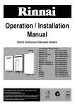
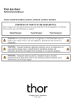
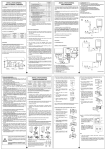
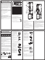
VENT TERMINATION
INSTALLATION-GENERAL
REU-VR2632FFUG / VRM2632FFUC
a
Flue Terminal
j
AC weatherproof external earthed power point is required within 1500 mm
of the appliance.
The appliance range can use up to 195MJ/h of gas.
IF THE GAS PIPE SIZE IS INSUFFICIENT, THE CUSTOMER WILL NOT
GET THE FULL PERFORMANCE BENEFIT. An approved isolation valve
MUST BE FITTED to the gas inlet. Connection size is R3/4(20A). This is
NOT an indication of the size of pipe required. Check the data plate for gas
inlet.
This appliance is not suitable for use as a pool heater.
Never connect an earth wire to gas supply line.
door
c
e
e
h
500mm to the
end of flue
d
P
g
d
M
I
140mm
T
g
k
Flue Terminal
Air Intake
b
T
Flue terminal section
1050mm
See note 2
T = Flue terminal
I = Mechanical air inlet
Ref.
Shading indicates prohibited
areas for flue terminals
M = Gas meter
P = Electricity meter or fuse box
a
Below eaves, balconies and other projections:
b
From the ground, above a balcony or other surface †
c
From a return wall or external corner †
300
d
From a gas meter (M)
1000
e
From an electricity meter or fuse box (P)
500
·
Air Intake
Appliances over 50 MJ/h input
Flue terminal
assembly
1050mm
500mm to the
end of flue
300
300
Deck tight or lead
collar flushing
f
From a drain pipe or soil pipe
75
g
Horizontally from any building structure † or obstruction facing a
terminal
500
h
From any other flue terminal, cowl, or combustion air intake †
300
j
Horizontally from an openable window, door, non-mechanical air inlet, or any other opening
into a building with the exception of sub-floor ventilation:
·
·
·
·
Deck tight or lead
collar flushing
Min. clearances
(mm)
Fan assisted
Item
Appliances up to 200 MJ/h input
300
Appliances over 200 MJ/h input up to 250 MJ/h input †
500
Appliances over 250 MJ/h input †
1500
All fan-assisted flue appliances, in the direction of discharge
1500
Bracket to
support flue
Bracket to
support flue
Over 2m Condensate
Trap must be fitted.
k
From a mechanical air inlet, including a spa blower
n
Vertically below an openable window, non-mechanical air inlet, or any other opening into a
building with the exception of sub-floor ventilation:
·
·
·
·
This appliance is for INDOOR use.
j
h
k
140mm
c
T
n
The appliance weighs approx. 21kg, depending on the wall on which it is to
be mounted must be capable of supporting it and associated pipework.
Ensure that suitable fixing screws or bolts are used to secure the appliance
to the wall. Bracket and fixing hole locations are shown overleaf.
Connect hot and cold water and gas pipes. Approved valves MUST BE
FITTED to both the cold water inlet and the gas inlet.
In areas where the water pressure is over 1000 kPa, a pressure limiting
valve must also be fitted. Both connections are R3/4(20A). Locations are
shown overleaf.
j
openable
window
f
The top bracket has a keyhole slot so that the appliance can be positioned
by hanging it on one screw, then the other screws can be secured. After
determining the most suitable position, fix the appliance to the wall.
h
1000
Space heaters up to 50 MJ/h input
150
Other appliances up to 50 MJ/h input
500
Appliances over 50 MJ/h input and up to 150 MJ/h input
1000
Appliances over 150 MJ/h input
1500
125mm
970mm
lengths or
cut to size
Vertical Adaptor
(purchased as
part of flue system
Over 2m Condensate
Trap must be fitted.
Vertical Adaptor
(purchased as
part of flue system
VR2632FFUG/VRM2632FFUC
adaptor suppried
with the appliance
49mm
60.7mm
VR2632FFUG/VRM2632FFUC
adaptor suppried
with the appliance
125mm
970mm
lengths or
cut to size
49mm
60.7mm
† Unless appliance is certified for closer installation
POSITIONING
note 1. All distance are measured to the nearest part of the terminal.
note 2. Prohibited Area below electricity meter or fuse box extends to
ground level.
This internal model is an internally mounted, power flued appliance.
IT MUST ONLY BE FITTED INSIDE THE BUILDING.
When determining a suitable position for the appliance, the length of hot
water pipe runs should be taken into consideration. In principle, the
appliance should be as close as possible to the most often used taps, or in
a central location between taps, showers etc.
See diagram overleaf for position of gas, water and power connections.
The location of the flue terminal must comply with the clearances shown in
the following diagram.
600mm 1.8m
to floor
600mm 1.8m
to floor
COAXIAL FLUEING FOR INTERNAL MODELS
Rinnai internal models descrided in this manual must use the coaxial
Rinnai FF flue components. The use of non Rinnai FF flue
components may result in a dangerous situation and violates
regulations. It can be installed to a maximum length of 9 metres and
with a maximum of three 90º bends.
If flue length exceeds 1.5m, dipswitch 1 of SW1 is to be
switched to the 'OFF' position as shown.
TESTING AND COMMISSIONING
1. Before final connection of the water heater purge gas, hot water and
cold water supply lines. Swarf in either the gas or water supplies may
cause damage.
If flue length exceeds 2m, connect a drain pipe in accordance with the
FF flueing instructions. It must be supplied by the installer.
2. Turn on gas and cold water supplies.
8. With all gas appliances in operation at maximum gas rate, check the
inlet gas pressure. If the pressure is lower, the gas supply is inadequate
and the appliance will not operate to specification. It is the Installers
responsibility to check the gas meter, service regulator and pipe work
for correct operation/sizing and rectify as required. Note that the gas
regulator on the appliance is electronically controlled and factory
pre-set. Under normal circumstances it DOES NOT need adjustment
during installation.
3. Test for water leaks and gas escapes near the unit.
9. Close hot water taps including the shower.
4. Isolate gas supply. Remove test point screw located on the gas inlet
connection and attach pressure gauge.
5. Turn the power 'on' at the power point socket and turn on gas.
6. Open all available hot water taps. (CAUTION: Ensure building
occupants do not have access to hot water outlets during this
procedure.)
7. Operate ALL other gas appliances at their maximum gas rate, in
accordance with manufacturers instructions.
1
Kitchen
VR2632FFUG
MC-91-2A*
or
MC-100V-1A
Bathroom 1
MC-91-2A*
or
BC-100V-1A
VRM2632FFUC
Bathroom 2
MC-91-2A*
or
BC-100V-1A
1. Determine the most suitable position for the remote controller.
1. Determine the most suitable position
for the controller.
Bathroom 3
MC-91-2A*
Outline of Remote Controller
41.5
* When a MC-91-2A Temperature Controller is used for this application
the installer may set this unit as kitchen controller.
• Note: For details on how to program the MC-91-2A remote control see
Appendix 1. MC-91-2A CONTROLLER PROGRAMMING.
5. Connect the cable to the remote
controller.
fig.1
Controllers must be installed in shaded and clean locations. They
should be fitted out of reach of children (suggested height from floor at
least 1500mm). Controllers are water resistant, however, durability is
improved when positioned outside the shower recess or at least
400mm above the highest part of a sink, basin or bath.
4. Affix the double sided self-adhesive
seal to the back of the controller
(Fig. 3).
Remote Control
Cable
104
Securing
Screw
Ø20 Cable Access
202
Fig. 1
Controller Cable
Connector
Fig. 2
fig.2
Connector
Backing Seal
5. Carefully remove the face plate from
the controller, do this by placing
your thumbs on the front of the
digital display and while hooking
your fingers behind top of plate and
gently push as shown in Fig. 4.
Face Plate
6. Fix the controller to the wall and
fasten with Philip's head screws as
shown in fig.4.
POSITIONING OF CONTROLLERS
3. Run the cable through the hole in
the wall-ensuring that the end fitted
with the conector is near the
controller (Fig. 2).
Wire
Hole
90
4. Remove face plate from the remote
control, using a flat-blade screw
driver. (fig.3)
Not Available
Securing
Screw
ø20
3. Run the cable through the hole in
the wall - ensuring that the end fitted
with the connector is near the
controller. (fig.2)
Outline of Water Controller
181
2. Drill 3 holes, locating the cable
access as shown in Fig. 1.
120
2. Drill 3 holes in the wall, as shown in
fig.1, one for the cable and two for
the securing screws. Ensure holes
are drilled. Fit wall plugs if required.
REMOTE CONTROLLER
Name
FITTING THE ‘DELUXE BATHROOM’ CONTROLLER (BC-100V-1A)
83
INSTALLATION-GENERAL
REMOTE CONTROLLER
FITTING THE ‘UNIVERSAL’ CONTROLLER (MC-91-2A)
fig.3
Remove film
to expose
self-adhesive
Fig. 3
Face Plate
7. Remove the protective plastic film
from the controller face as shown in
fig.4.
6. Connect the cable to the water
controller.
Film
7. Fix the controller to the wall using
the appropriate fixings as shown in
Fig. 5.
Screw
fig.4
8. Replace face plate.
DO NOT INSTALL THE CONTROLLERS:
•
NEAR A HEAT SOURCE, SUCH AS A COOK TOP, STOVE OR OVEN.
HEAT, STEAM, SMOKE AND HOT OIL MAY CAUSE DAMAGE.
•
IN DIRECT SUNLIGHT.
•
OUTDOORS UNLESS AN ENCLOSURE IS PROVIDED WHICH
PROTECTS THE CONTROLLER AGAINST SUNLIGHT AND DUST
INGRESS.
Note: For details on how to program the MC-91-2A remote control see
Appendix 1. MC-91-2A CONTROLLER PROGRAMMING.
Fig. 4
Remote controls operate at extra low voltage (12 Volts DC) which is
supplied from the appliance. Controllers are supplied with 15m of
electrical cable. The cable wires for connection to the appliance are
fitted with spade terminals. Extension cables are available from Rinnai.
Alternatively, a two core sheathed (double insulated) flex with minimum
cross-sectional area of 0.5mm2 can be used. Maximum cable length is
50 m.
1. Remove the power plug of the water heater from the electric power socket.
A
3. Swing the 'Ezi connect' cable connector door open and thread the cable through the weather seal
of the cable access hole B in the direction shown allowing sufficient cable length so that the
sheath of the cable can be secured with cable clamp C supplied with the transceiver.
4. Loosen screw terminals D and E and connect the cable spade connectors to these terminals
and re-tighten. Polarity is not important, either wire colour can be connected to either terminal.
5. Return the 'Ezi connect' cable connector to the original position taking care not to damage cable
wires in the process and replace the retaining screw A .
120
Ø20 Cable Access
Appendix 1. MC-91-2A CONTROLLER PROGRAMMING
3. Fix the mounting bracket to the wall
using the appropriate fixings.
STEP 1:
4. Run the cable through the hole in
the wall.
6. Connect the cable to the controller
as shown in Fig 3. At this point
cables from other controllers (if
fitted) may also be connected to the
screw terminals of the Kitchen water
controller (Fig. 4) eliminating the
need for multiple cable runs directly
to the water heater.
7. Fasten the controller to the wall
mounting bracket as shown in Fig.
5.
A
128
Fig. 5
Fig.1
5. Carefully remove face plate from the
remote controller, using a flat-blade
screw driver (Fig. 2).
To connect up two cables to the 'Ezi connect' cable connector
2. Remove the retaining screw
2. Use the wall mounting bracket as a
template to drill 3 holes, locating the
cable access as shown in Fig. 1.
Screw Securing Points
REMOTE CONTROL CABLES
1. Determine the most suitable position
for the controller.
Outline of Water Controller
FITTING THE ‘DELUXE KITCHEN’ CONTROLLER (MC-100V-1A)
Fig. 2
STEP 2:
Check that the display on ALL
controllers is lit and displaying a
temperature when 'switched on'. If
any ONE of the controller displays
two dashes (see fig.2) in the display
repeat STEP 1.
Fig. 3
fig.2
Fig. 4
Note:
B
Connecting Three or Four Controllers
F
F
F
Fig. 5
Repeat steps 1, 2 and 3 above.
To connect three or four cables, separate all the cables to be fitted into
pairs. Cut off the existing spade connectors from each pair and reterminate each pair into a new spade connector (available from your
local electrical component retailer) F so that there are only two sets
of spade connectors (4 spade connectors in total) to be terminated.
Repeat steps 4 and 5 above.
fig.1
For the controller in the KITCHEN
only, press and hold the 'Transfer'
and 'On/Off' buttons simultaneously
(see fig.1) until a 'beep' is heard
(approximately 5 seconds).
Three
Cables
Four
Cables
2
•
If the kitchen controller is replaced, repeat STEP 1 above for the
replacement controller.
•
If the kitchen controller is swapped with another controller (for
example, the controller fitted in a bathroom), repeat STEP 1 for the
controller moved from the kitchen to the bathroom. Then perform
STEP 1 for the controller moved from the bathroom to the kitchen.
10. Inspect and clean the strainer located on the cold water inlet
connection. This procedure may need to be repeated to ensure the
strainer remains clear, especially on new installations.
11. Confirm the hot water delivery temperature using a thermometer. This
appliance is factory preset to 60C. Take precautions against scald.
12. After testing is completed, explain to the householder the functions and
operation of the water heater.
REU-VR2632FFUG / VRM2632FFUC
GAS PRESSURE SETTING
DIMENSIONS
DURING PRESSURE TESTING OF THE CONSUMER PIPING
ENSURE GAS COCK SITUATED BEFORE UNIT IS SHUT-OFF.
350
The regulator on the Infinity is electronically controlled and factory pre-set.
Under normal circumstances it does not require adjustment during
installation. Perform this procedure only if the unit is not operating correctly
and all other possible causes for incorrect operation have been eliminated.
DRAIN PIPE
INLET(5/8)
330
72.5
17
Dip.SW1(8P)
Dip.SW2(6P)
fig.1
Burner test point
5. Attach pressure gauge to burner test
point, located on the gas control.
(fig. 2)
600
6. Turn 'ON' the gas supply.
7. Turn 'ON' power supply.
fig.2
fig.3
fig.4
9. Set the appliance to 'Forced Low'
combustion by setting No. 7 switch of
the Dip.SW1 set of dip switches to 'ON'.
(fig. 3)
Pressure Setting LOW
0.18kPa
NG
LPG
12. Set the appliance to 'Forced High'
combustion by setting both No. 7 and
No. 8 switches of the bottom Dip.SW1
set to 'ON'. (fig. 5) Ensure maximum
water flow.
fig.5
17
Table. 1
A
0.24kPa
11. Remove rubber access plug and
adjust the regulator screw on the
modulating valve (fig. 4) as required to
the pressure. (Table 1) Replace rubber
access plug.
Dip.SW1
REMOTE CONTROL
CABLE ACCESS
CABLE ACCESS
COLD WATER INLET
Pressure Setting HIGH
NG
0.94kPa
LPG
1.11kPa
A DEMENSION
GAS
41
COLD
HOT
51
Dip.SW1
fig.6
15. IMPORTANT: Set No. 7 and 8 switches on the bottom (Dip.SW1) set
of switches to 'OFF' to return the appliance to 'Normal' combustion.
(fig. 6)
HOT WATER OUTLET
27
16. Close hot water tap.
89(GAS)
Table. 2
60(COLD)
14. Adjust the high pressure Potentiometer
(POT) on the Printed Circuit Board
(PCB) as required to the pressure
shown Table 2.
GAS CONNECTION
81(HOT)
13. Check the burner test point pressure.
2
10. Check the burner test point pressure.
STATUS MONITOR
(Only VRM2632FFUC)
Dip.SW1
147(ELEC.)
8. If remote controllers are fitted, turn the
unit 'ON' at the kitchen controller,
select
the
maximum
delivery
temperature and open a hot water
tap
fully.
(CAUTION:
Ensure
building occupants do not have access
to
hot water outlets during this
procedure.)
571
Note: 'ON' towards front, 'OFF' towards rear.
86
Dip.SW2
2. Turn 'OFF' power supply.
4. Check gas type switches (fig. 1) are in
the correct position (No.1 switch of
Dip.SW2 'ON' = NG, 'OFF' = LPG).
10~50
25.5
1. Turn 'OFF' the gas supply.
3. Remove the front cover from the
appliance.
224
ø127
ø80
75.7
FAILURE TO DO SO MAY RESULT IN SERIOUS
DAMAGE TO THE APPLIANCE AND POSSIBLE INJURY.
627(WALL INSTALLATION PITCH)
WARNING
42
CABLE ACCESS
27
REMOTE CONTROL
CABLE ACCESS
31
20
89
110
17. Turn OFF the gas supply and power supply.
18. Remove pressure gauge, and replace sealing screw.
19. Turn 'ON' the gas supply and power supply.
20. Operate unit and check for gas leaks at test point.
21. Replace the front cover of the appliance.
3
WIRING DIAGRAM
DIAGNOSTIC POINTS
080 00012 31569 9
REU-VR2632FFUG-ASN
REU-VRM2632FFUC-ASN
4
U287-2780(01)