1
SH S
[RaFTZ
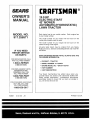
MODEL NUMBER 91
•
•
•
•
•
®
OWNER'S
MANUAL
Assembly
Operation
Customer Responsibilities
Service and Adjustments
Repair Parts
CAUTION:
Read
and follow
FOR CONSUMER
all safety
ASSISTANCE
rules
and instructions
before
operating
HOT LINE, CALL THIS TOLL FREE NUMBER:
this
1-800-659-5917
equipment.
SAFETY
Practices RULES
for Ride-On
Safe Operation
Mowers
IMPORTANT:
THIS CUTTING MACHINE IS CAPABLE OF AMPUTATI _IG HANDS AND FEET AND THROWING
OBJECTS.
FAILURE TO OBSERVE THE FOLLOWING
SAFETY INSTRUCTIONS
COULD RESULT IN SERIOUS INJURY OR DEATH.
L
GENERAL
OPERATION
Ill. CHILDREN
Read. understand, and follow all instructions in the manual
Tragic accidents can occur if the operator
is not alert to the
and on the machine before starting+
presence of children.
Children are often attracted to the
,
Only allow responsible adults who are familiar with the
machine
and the mowing activity.
Never assume that
nstructions, to operate the machine.
children will remain where you last saw them.
=
Clear the area of objects such as rocks, toys, wire, etc..
+
Keeo children out of the mowing area and under the watchful
which could be picked up and thrown by the blade.
care of another responsible +adult.
•
Besure the areais clear of other people before mowing. Stop
+
Be alert and turn machine off if children enter the area.
machine if anyone enters the area.
•
Before
and when backing, look behind and down for smatl
=
Never carry passengers.
children+
,
Do not mow +nreverse unless absolutely necessary. Always
•
Never carry children. They may fail off and be seriously
look down and behind before and while backing.
injured or interfere with safe machine operation.
,
Be aware of the mower discharge direction ann tie not point
°
Never allow chitdren to operate the machine.
it at anyone. De not operate the mower without either the
entire grass catcher or the guard m place.
Use extra care when approaching blind corners, shrubs,
trees, or other objects that may obscure vision
•
Slow down before turning.
•
Never leave a running machine unattended. Always turn off
IV. SERVICE
blades, set parking brake, stop engine, and remove keys
=
Use extra care in handling gasoline and ether fuels. They are
before dismounting,
fiammabie and vapors are explosive.
+
Turn off blades when not mowing,
Use only an approved container
•
Stop engine before removing grass catcher or unclogging
chute.
Never remove gas cap or add fuel with the engine
running. Allow engine to cool before refueling. Do not
+
Mow only in daylight or good artificial light,
smoke.
Do not operate the machine while under the influence of
Never refuel the machine indoors.
alcohol or drugs.
Never store the machine or fue! container inside where
Watch for traffic when operating near or crossing roadways.
there is an open flame, such as a water heater.
Use extra care when loading or unloading the machine into
Never run a machine inside a closed area.
a trailer or truck.
=
Keep nuts and belts, especially blade attachment bolts, tight
II. SLOPE OPERATION
and keep equipment in good condition.
,
Never tamper with safety devices.
Check their proper
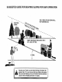
Slopes are a major factor related to loss-of-control
and
operation regu+arly.
tipover accidents,
which can result in severe injury or
=
Keep machine free of grass, leaves, or other debris build+up.
death. All slopes require extra caution,
ff you cannot back
Clean oil or fuel spillage.
Allow machine to cool before
Jp the slope or if you feel uneasy on it, do not mow it.
storing.
=
Stop and inspect the equipment if you strike an object.
DO:
Repair, if necessary, before restarting.
=
Mow up and down slopes, not across.
•
Never make adjustments or repairs with the engine runmng+
•
Remove obstacles sucn as rocks, tree Iimbs, etc.
Grass catcher componentsare subject to wear, damage, and
Watch for holes ruts, or bumps.
Uneven terrain could
deterioration,
which could expose moving parts or atlow
overturn the machine: Tall grass can hide obstacles.
objects to be thrown. Frequently check components and
Use slow speed. Choose a !ow gear so that you will not have
replace with manufacturer's recommended oarts, when necto stop or shift while on the slope.
essary,
•
Follow the manufacturer's
recommendations
for wheel
•
Mower blades are snare and can cut, Wrap the blade(s) or
weights or counterweights to improve stability.
wear gfoves, and use extra caution when servicing them
•
Use extra care with grass catchers or other attachments,
+
Check brake oeeration freauentiy.
Adiust and service as
These can change the stability of the machine.
required.
+
Keep all movement on the slopes slow and gradual Do not
make sudden changes m speed or direction.
Look for this symbol to point out important
safety
precautions.
It
means
•
Avoid starting or stopping on a SlOPe. If tires lose traction
disengage the blades and proceed slowly straightdewn the
CAUTION!!!
BECOME ALERT1!!
YOUR
siope.
SAFETY !S !NVOLVED.
DO NOT:
+
•
,
=
DO not turn on slopes untess necessary, andthen, turn slowly
and gradually downhill, if possible.
Do not mow r ear drep-offs, ditches, or embankments. The
mower could suddenly turn over if a wheel is over the edge
of a cliff or ditch, or if an edge caves in.
Do not mow on wet grass. Reduced traction could cause
sliding.
Do not try to stabilize the machine by putting your foot on the
ground.
Do not use grass catcher on steep slopes.
A WARNING
A
The engine exhaust fromthis
product contains
chemicals
known to the State of California
to
cause cancer, birth defects, or other reproductive harm.
2
CONGRATULATIONS
on your purchase of a Sears
Tractor, it has been designed, engineered and manufactured to give you the best possible dependability and
performance.
Should you experience any problem you cannot easily
remedy, please contact your nearest Sears Authorized
Service Center!Department
Department. We have competent, well-trained technicians and the proper tools to
service or repair this t_'actor.
Please read and retain this manual. The instructions wilt
enable you to assemble and maintain your tractor properly.
Always observe the "SAFETY RULES".
'l
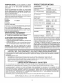
19.0
GASOLINE CAPACITY
AND TYPE:
5 QUARTS
UNLEADED
OIL TYPE (APt-SFiSG):
SAE 30 (above 32°F)
SAE 5W-30 (below 32°F)
OIL CAPACITY:
3.0 PINTS
SPARK PLUG:
GAP: .030")
CHAMPION
VALVE CLEARANCE:
INTAKE:
EXHAUST:
GROUND SPEED (MPH):
FORWARD:
REVERSE:
TIRE PRESSURE:
ON A PLATE UNDER THE SEAT.
YOU SHOULD RECORD BOTH SERIAL NUMBER AND
DATE OF PURCHASE
AND KEEP IN A SAFE PLACE
FRONT:
REAR:
CHARGING
3 AMPS BATTERY
5 AMPS HEADLIGHTS
FOR FUTURE
BATTERY:
AMP/HR:
MIN. CCA:
CASE SIZE:
BLADE BOLT TORQUE:
30-35 FT. LBS.
DATEOF
917.256571
PURCHASE
THE MODEL AND SERIAL
NUMBERS
WILL BE FOUND
REFERENCE.
MAINTENANCE
CUSTOMER
is available on this prodstore for details,
RESPONSIBILITIES
Read and observe the safety rules.
Follow a regular schedute m maintaining,
caring for and
using your tractor.
Follow the instructions
under "Customer ResponsibilF
ties" and "Storage"
sections of this owner's manual.
WARNING:
This tractor is equipped with an internal
combustion eng_ne and should not be used on or near any
unimproved forest-covered, brush-covered or grass_cov-
LIMITED
SYSTEM:
AGREEMENT
A Sears Maintenance
Agreement
uct. Contact your nearest Sears
•
SPECIFICATIONS
HORSEPOWER:
MODEL
NUMBER
SERIAL
NUMBER
•
PRODUCT
TWO YEAR WARRANTY
REGULAR
RJ19LM
.004"- .006"
.007" - .009"
0 - 5.5
0- 2.4
14 PSI
10 PSI
30
240
UIR
ered land unless the engine's exhaust system is equtpped
with a spark arrester meeting applicable local or state taws
(if any). If a spark arrester is usee, it should be maintained
in effective working order by the operator.
In the state of California the above is required by law
(Sectior 4442 of the California Public Resources Code).
Other states may have similar laws. Federal laws apply on
federal land& A spark arrester for the muffler is available
through your nearest Sears Authorized Service Center/
Department (See REPAIR PARTS section of this manual).
ON CRAFTSMAN
RIDING EQUIPMENT
For two (2) years from the date of purchase, if this Craftsman Riding Equipment is maintained, lubricated and tuned up according
to the instructions in the owner's manual, Sears witi repair or replace, free of charge, any parts found to be defective in material or
workmanship.
This Warranty does net cover:
•
Expendable items which become worn during normal use such as blades, spark plugs, air cleaners, belts, etc.
°
Tire replacement or repair caused by punctures from outside objects, such as, nails thorns, stumps, or glass.
•
Repairs necessary' because of operator abuse, negligence, improper storage or accident or the faiiure to maintain the
equipment according to the instructions contained in the owner's manual
°
Riding equipment used for commercial or rental purposes.
LIMITED 90 DAY WARRANTY
ON BATTERY
For ninety (90) days from date of purchase, f any battery included with this riding equipment proves defective in material or
workmanship and our testing determines the battery will not hold a charge. Sears wilFreplace the battery at no charge.
1N-HOME WARRANTY SERVICE ON YOUR CRAFTSMAN RIDING EQUIPMENT IS AVAILABLE AT NO-CHARGE
FOR 30
DAYS FROM THE DATE OF PURCHASE, PLEASE CONTACT YOUR NEAREST SERVICE CENTER. AFTER 30 DAYS FROM
THE DATE OF PURCHASE, WARRANTY SERVICE IS AVAILABLE BY TAKING YOUR CRAFTSMAN RIDING EQUIPMENT TO
YOUR NEAREST SEARS SERVICE CENTER. (IN-HOME WARRANTY SERVICE WILL STILL BE AVAILABLE AFTER 30 DAYS
FROM THE DATE OF PURCHASE BUT A STANDARD TR_P CHARGE WILL APPLY.) THIS WARRANTY APPUES ONLY
WHILE THtS PRODUCT IS IN THE UNITED STATES.
This Warranty gives you specific legal rights, and you may also have other rights which may vary from state to state.
SEARS, ROEBUCK AND CO., D/817 WA, HOFFMAN ESTATES, tL 60179
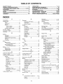
TABLE OF CONTENTS
OPERATION ..........................................................
11-14
MAINTENANCE SCHEDULE .....................................
15
SERVICE AND ADJUSTMENTS ...........................
19-25
STORAGE ...................................................................
26
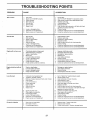
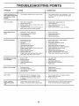
TROUBLESHOOTING
...........................................
27-28
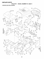
REPAIR PARTS -TRACTOR ................................
30-47
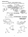
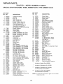
REPAIR PARTS - ENGINE ....................................
48-53
PARTS ORDERtNGISERVIGE .................. BACK PAGE
SAFETY RULES ............................................................
2
PRODUCT SPECIFICATIONS ......................................
3
CUSTOM ER RESPONSIBILITIES:
.................... 3, 15-18
WARRANTY ..................................................................
3
TAB LE OF CONTENTS .................................................
4
INDEX ............................................................................
4
TRACTOR ACCESSORIES ..........................................
5
ASSEMBLY ...............................................................
7-9
INDEX
A
Accesso ries............................................
5
Adjustments:
Brake .................................... _...... 2!
Carburetor ................ :.................. 24
Mower:
Front-To-Back ........................ 20
Side-To-Side .......................... 20
Throttle Control CaMe ................. 24
Air Fiffer. Engine .................................
17
Air Screen, Engine ............................. 17
Assembly ...........................................
7-9
B
Battery:
Charging .....................................
Cleaning ......................................
Starting with Weak Battery .........
Storage .......................................
Terminals ....................................
Betts:
Motion Drive
Removal/Replacement
..........
Mower Blade Drive
Removal/Replacement
..........
Blade:
Sharpening ..................................
Replacement ...............................
Brake Adjustment ..............................
C
16
16
23
26
16
21
21
16
16
21
Carburetor Adjustment ....................... 24
Controls, Tractor ................................ 12
Customer Responsibilities ......... 3.15-18
Engine:
Air Filter ...................................
17
Air Screen. Engine .................. 17
Battery ....................................
16
Cooling Fins Engine ............... 18
Engine Oit ...............................
17
Fuel Filter ................................
18
Spark Plugs ............................. 18
Tractor:
Blades .....................................
16
Lubrication Chart ..................... 15
Maintenance Schedule ........... 15
Tire Care ........................ 8.16.22
Cutting He=ght, Mower .......................
12
E
Electrical:
Interlocks and Relays ................. 23
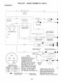
Schematic ................................... 29
Wiring Diagram ........................... 30
Engine:
Air Filter ......................................
17
Air Screen .................................
17
Cooling Fins, Engine ................... 18
Oil Change ..................................
17
Oil Level ................................. 13,17
Oil Type .......................................
t7
Preparation ................................ t3
Repair Parts ........................... 48-53
Starting ........................................
13
Storage .......................................
26
F
Filters:
Air ................................................
t7
Fuei .............................................
!8
Fuel:
Type ............................................
13
Storage .......................................
26
Fuse ...................................................
23
G
Gauge Wheels .....................................
H
Hood Removal/installation
L
8
................. 23
Leveling Mower Deck ......................... 20
Lubrication Chart ..............................
15
M
Maintenance Schedule
.................... 15
Mower:
Adjustment. Front-to-Back .......... 20
Adjustment Side-to-Side ............. 20
Blade Sharpening
.................... 16
Blade Replacement ..................... 16
Cutting Height ............................. 12
installation .................................
19
Oeeration ............................... 11-14
Removai .....................................
19
Mowing Tips .......................................
14
Muffler ................................................
18
Spark Arrester .......................... 3.40
Mulcher Plate .......................................
9
O
Oil:
Cold Weather Conditions ....... 13,17
Engine .........................................
17
Storage .......................................
26
4
Operation ......................................
11-14
Operating Mower ..........................
12-13
O9tions:
Accessories ...................................
5
Spark Arrester .......................... 3.40
P
Parking Brake ................................
11-12
Parts Bag .............................................
6
Parts. Replacement/Repair
........... 30-47
Product Specifications .......................... 3
R
Repair Parts ..................................
S
30-47
Safety Rules .........................................
2
Seat ......................................................
8
Service and Adjustments
.............. 19-25
Brake ...........................................
21
Carburetor ..................................
24
Fuse ............................................
23
Hood Removal/Installation
........... 23
Motion Drive Belt
Removal/Replacement
.......... 21
Mower Blade Drive Belt
Removal/Replacement
.......... 21
Mower Adjustment:
Front-to-Back ......................... 20
Side-to-Side ........................... 20
Mower Installation ....................... 19
Mower Removal .......................... 19
Tire Care .............................
8.16.22
Sfooe Guide Sheet .............................
55
Spark Plugs ........................................
18
Specifications ........ :..............................
3
Starting the Engine ....................... 13-14
Steering Wheel ...............................
7,22
Stopping the Tractor ........................... 12
Storage ...............................................
26
T
Throttle Control Cable Adjustment ..... 24
Tires ...........................................
8.16.22
Trouble Shooting Chart .................. 27-28
Transaxte
Repair Parts .................
W
46-47
Warranty ..............................................
Wiring Diagram ..................................
Wiring Schematic ...............................
3
30
29
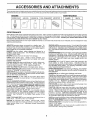
ACC
AN
ATTACHMENTS
,,.i,,1_ i,, i,,i,i,U!l u,i ,u
ii n,
ilUll ii,i
These accessories and attachments were available through most Sears retail outlets and service centers when the tractor was purchased.
Most Sears stores can order these items for you when you provide the model number of your tractor.
MAINTENANCE
ENGINE
SPARK PLUG
GAS CAN
ENGINE OIL
FUEL STABILIZER
I
AIR FILTER
BLADES
BELTS
2
PERFORMANCE
Sears offers a wide variety of attachments that fit your tractor.
you. This list was current at the time of publication; however,
may be made in these attachments, or some may no longer
accessories
and attachments that are available for your
Most of these attachments do not require additional hitches
attaching and detaching,
Many of these are listed below with brief explanations of how they can help
it may change in future years - more attachments may be added, changes
be available or fit your model Contact your nearest Soars store for the tractor.
or conversion kits (those that do are indicated) and are designed for easy
AERATOR promotes deep root growth for a healthy lawn. Tapered 2.5qnch steel spikes mounted on 10-inch diameter discs
puncture holes in soil at close intervals to let moisture soak in.
Steel weight tray for increased penetration.
BAGGER lets you ceilect
grass clippings and leaves for a
healthier, nearer looking lawn. Two Permanex containers hold
30-gallon plastic bags.
BUMPER protects front end of tractor from damage.
CARTS make hauling easy. Variety of sizes available, ptus
accessories such as side panel kits, tool caddy, cart cover,
protective mat and dolly.
CORING AERATOR takes small plugs out of soil to aifow moisture and nutrients to reach grass roots." 36-inch swath. 24
hardened steel coring tips. 150 lb. capacity weight tray,
EASY OIL DRAIN VALVE makes oil changes easier, faster.
FRONT NOSE ROLLER canters in front of mower deck to reduce
chances of "scalping" on uneven terrain.
GANG HITCH lets you tow 2 or 3 pull-behind attach ments at once,
such as sweepers, dethatchers, aerators (not for use with rollers,
carts or other heavy attachments).
GAUGE WHEELS on both sides of the mower deck reduce
chances of "scaiping" on uneven terrain. For mowerdecks notso
equipped.
MULCH RAKE/DETHATCHER
loosens soil and flips thatch and
matted leaves to lawn surface for easy pickup. Twenty spring tine
teeth. Usefuttopreparebareareasforseeding.
Avaitableforfront
or rear mounting.
HIGH PERFORMANCE
REEL-ACTION
SPRING TINE DETHATCHER
covers 36-inch wide path and
tosses thatch into large hopper. Mounts behind tractor.
MULCHING CLOSE-OUT PLATE KIT, once installed, tets you
muich, discharge or bag clippings (bagger optional) without
changing blades. For models not equipped as 3-in-! Convertible
mowers. See "MOWER" in the Repair Parts section of this
manual.
RAMP TOPS AND FEET let you Joad and untoad tractor from a
pickup truck. Use with 2 x 8 or 2 x 10 lumber.
ROLLER for smoother lawn surface.
36-inch-wide,
184nch
diameterwater-tight
drum holdsupto390]bs,
ofweight. Rounded
edges prevent harm to turf. Adjustable scraper automatically
cleans drum.
SNOW BLADE for snow removal only. 14-inch high, 484nch wide
blade clears 42-inch path when angled left or right: Raises, lowers
with side lever, Adjustable skids; replaceable, reversible scraper
bar. (Use with tire chains and wheel weights and/or rear drawbar
weight,)
SNOWTHROWER has 40-inch swath, Drum-type auger handles
powdery and wet/heavy snow. Mounts easily with simple pin
arrangement, Discharge chute adjusts from tractor seat. 6-inch
diameter spout discharges snow 10 to 50 feet, Lift controlled at
tractor seat. (Use with chains and wheel weights and/or rear
drawbar weight.)
SPRAYERS use 12-volt DC electric motor that connects to the
tractor battery or other 12*volt source.
Includes booms for
automatic spraying and hand held wand for spot spraying. Wand
has adjustable spray pattern. For applying herbicides, insecticides, fungicides and liquid fertilizers.
SPREADER/SEEDERS
make seeding, fertilizing, and weed kitl!ng easy. Broadcast spreaders are also useful for granular de o
=cers and sand.
SWEEPERS Iet you collect grass clippings and leaves.
TILLER has 5 hp engine and 36-inch swath to prepare seed beds,
cultivate and compost garden residue. Tiller has its own built-in
liftand depth control system and does NOT require a sleeve hitch.
Fits any lawn, yard or garden tractor. Simply hook up to the tractor
drawbar and go! Optional
accessories
convert unit for
dethatching; aerating, hitling...without tools.
TIRE CHAINS are heavy duty; closely spaced extra-large cross
links give smooth ride, outstanding traction.
TRACTOR CAB has heavy duty vinyl fabric over tubular steel
frame, ADS plastic top; clear plastic windshield offers 360 degree
visibility. Hinged metal doors with catch. Keeps operator warm
and dry. Remove vinyl sides and windshields for use as sun
protector in summer. Optional accessories
include:
tinted/
tempered solid safety glass windshield with hand operated wiper;
12-volt amber caution light for mounting on cab top.
VACS for powerful collection of heavy grass clippings and leaves.
Optional wand attachment to pick up debris in hard-to-reach
places. VAC/CHIPPER includes a chipper=shredder.
WEIGHT BRACKET for drawbar for snow removal applications.
Uses (1) 55 lb_ weight,
WHEEL WEIGHTS for rear wheels provide needed tractiOn for
snow removal or dozing heavy materials.
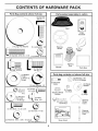
CONTENTS
Parts Bag contents
-/ f
PACK
shown full size
f--_
/-
OF HARDWARE
(1) Hex Bolt
3/8-16 x 1
"---.,
o
/
E_
I
Seat
Video
Cassette
/
/t/
(1) Large Flat Washer
(1) Lockwasher
'1) Hex Bolt 5/16-18 x 1-1/4
Mulcher
Plate
8
Parts Bag
1/2-13 x 1
\
/
\ 17/32 x
_ 1-3/16,x t 2
Gauge
LO
/
(2) Washers 3/8
x 7/8 x 14 Gauge
__Wa_he'
_
(2) Shoulder
Bolts
(1) Lock Washer
f_._
|
_
_
_
Q_
-
H
Steering
Boot
-Manual
(1) Hex Bolt
./"
Steering
Wheel
(1) Locknut 5/16-18
___r
/
318
(2)
Look
Washers
(2)
Screws
#10
x 5/8
_ (2) Washers
//3/I6 x 3/4
x 16 Gauge
_
Steering Wheel
Adapter
(2) Weld
Nuts #10
(2) Centerlock Nuts
__ok
(5)
(2) Hex Bolts 1!4_20 x 3/4
©
1/2
Assemblys
(2) Gauge
Wheels
\
\.
(2) Keys
Steering
Wheel
Insert
Steering
Extension
Shaft
(2) Hex Nuts !/4-20
2) Washers
9/32 x 5/8 x 16 Gauge
.....
2 Lock Washers
Slope Sheet
1/4 ,
BLY
Your new tractor has been assembled at the factory with exce 3tion of those 3arts left unassembled for shipping purposes.
To ensure safe and 3roper operation of your tractor all parts and hardware you assemble must be tightened securely. Use
the correct tools as necessary to insure proper tightness.
TOOLS
REQUIRED
FOR ASSEMBLY
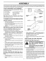
INSERT
A socket wrench set will make assembly eas_er. Standard
wrench stzes are listed.
3/8 HEX BOLT
_"--"--'--
(1) 5/16" wrench
(1) 3/4" Socket w!drive rachet
(2) 7/16" wrenches
Phillips Screwdriver
(1) 1/2" wrench
Tire pressure gauge
(2) 9/16" wrench
Utility knife
When right or left hand is mentioned in this manual, it
means when you are in the operating position (seated
behind the steering wheel).
3/8 LOCK WASHER
FLAT
WASHER
1
STEERING
WHEEL
/
STEERING
BOOT
TO REMOVE TRACTOR FROM CARTON
UNPACK
•
o
=
CARTON
ADAPTER
EXTENSION
Remove all accessible !oose parts and parts cartons
from carton (See page 6).
Cut. from top to bottom, along lines on all four corners
Of carton, and fay panels fiat.
Check for any additional loose Darts or cartons and
remove,
SHAFT
5116 HEX BOLT
BEFORE ROLLING TRACTOR OFF SKID
ATTACH
STEERING
ASSEMBLE EXTENSION
WHEEL
(See Fig. 1)
SHAFT AND BOOT
FIG. 1
•
Slide extension shaft onto lower steering shaft, Align
mounting holes in extension and lower shafts and
nstalt 5/16 hex bolt and focknut. Tighten securely.
IMPORTANT: TIGHTEN BOLT AND NUT SECURELY TO
18-22 FT. LBS TORQUE.
-
Place freewheei control n freewheeling position to
disengage transmission (See "TO TRANSPORT" in
the Operation section of this manual).
Roll tractor backwards off skid.
Place tabs of steering boot over tab slots in dash and
push down to secure.
Remove banding holding discharge guard up against
tractor.
INSTALL STEERING WHEEL
,
Position front wheels of the tractor so they are pointing
straight forward.
HOW TO SET UP YOUR TRACTOR
-
Slide steering wheel adapter onto steering shaft extension.
CONNECT
.
Position steenng wheel and sleeve assembly so cross
bars are horizontal (left to right) and slide onto adapter.
.
Assemble large flat washer_ 3/8 lock washer, 3/8 nex
bolt and tighten securely.
•
Snap steering
wheel.
wheel insert
TO ROLL TRACTOR
OFF SKID (See Operation section for location and function
of controis)
-
Press lift lever plunger and raise attachment lift lever to
its highest position
•
Release parking
oedal.
brake by depressing
(See Fig. 2)
nals. Before connecting battery, remove
metalDo bracelets,
wristwatch
CAUTION:
not short battery
termibands, rings, etc.
Positive terminal must be connected
first to prevent sparking from accidental grounding.
nto center of steering
=
Remove protective plastic from tractor hood and grill.
IMPORTANT: CHECK FOR AND REMOVE ANY STAPLES
IN SKID THAT MAY PUNCTURE TIRES WHERE TRACTOR
IS TO ROLL OFF SKID.
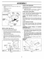
BA'n'ERY
Lift hood to raised position.
o
Open terminal access doors, remove terminal protective caps and discard.
-
If this battery is put into service after month and year
indicated on label (label located between terminals)
charge battery for minimum of one hour at 6-10 amps.
°
First connect RED battery" cable to positive (+) battery
terminal with hex bolt, fiat washer, lock washer and hex
nut as shown. Tighten securely.
-
Connect BLACK grounding cable to negative (-) battery
terminal with remaining nex bolt flat washer, lock
washer and hex nut, Tighten securely.
Close terminal access doors.
clutch/brake
•
ASSE
Use terminal access doors for:
=
•
BLY
CHECK
Inspection for secure connections
ware).
(to tighten qard-
Inspection for corrosion,
The tires on your tractor were overinflated at the factory for
shipping= purposes. Correct tire pressure _s important for
best cutting performance.
Testing battery.
-
•
Jumping (if required),
•
Periodic charging.
LOCK
WASHER
\
DISCARD TERMINAL
PROTECTIVE CAPS
k
TERMINAL
ACCESS
DOOR
Reduce tire pressure to PSI shown in "PRODUCT
SPECIFICATIONS" on page 3 of this manual.
CHECK
HEX NUT
\
_'
FLAT
WASHER
HE\
BOLT
\
CHECK
BELTS
I .
E
POSITIVE
(RED)
i i!_.
"i_
'_.=:
1-
.... _
.
CABLE
" _'_.
(BLACK)
NEGATIVE
CABLE
r
FIG. 2
INSTALL
DECK
FOR
Adjust seat before tightening adjustment bolt.
o Remove cardboard packing on seat pan.
o
Place seat on seat pan and assemble shoulder bolt.
-
Assemble adjustment bolt, lock washer and flat washer
loosely. Do not tighten.
Tighten shoulder bolt securely.
,
Lower seat into operating position and sit on seat.
-
Slide seat until a comfortable position is reached which
allows you to cress clutch/brake pedal all the way
down.
,
-
Get off seat without moving its adjusted position.
Raise seat and tighten adjustment bolt securely.
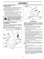
PROPER
BRAKE
GAUGE
WHEELS
TO
MOWER
DECK (See Fig. 4)
Assemble gauge wheels with tractor on a flat level surface.
-
Adjust mower to desired cutting hei,ght (See "TO ADJUST MOWER CUTTING HEIGHT in the Operation
section of this manual).
-
With mower in desired height of cut position, gauge
wh eels should be assembled so they are slightly off the
ground. Install gauge wheel in appropriate hole with
shoulder bolt, 3/8" washer and 3/8-16 Iocknut and
tighten securely.
-
Reoeat for opposite side installing
same adjustment hole.
GAUGE WHEEL
MOUNTING
BRACKET
\
3/8 _16
LARGE FLAT WASHER
FIG. 3
ALL
After you learn how to ooerate your tractor, check to see
that the brake is properly adjusted. See "TO ADJUST
BRAKE" in the Service and Adjustments section of this
manual.
SHOULDER
ADJUSTMENT
BOLT
OF
SYSTEM
SEAT PAN
BOLT \
POSITION
See the figures that are shown for replacing motion and
mower blade drive belts in the Service and Adjustments
section of this manual. Verify that the belts are routed
correctly.
ASSEMBLE
SEAT (See Fig. 3)
LEVELNESS
For best cutting results, mower housing should be properly
leveled.
See "TO LEVEL MOWER HOUSING" in the
Service and Adjustments section of this manual
CHECK
-
TIRE PRESSURE
FIG. 4
gauge wheel in
iNSTALL MULCHER
(See Figs. 5 & 6)
.
PLATE
DEFLECTOR
SHIELD
J ....
Install two latch hooks to mulcher plate using screw_
washer, lock washer, and wetd nut as shown.
NOTE: Pre-assembJe weld nut to latch hook by inserting
weld nut from the top with hook pointing down.
•
Tighten hardware securely.
•
Raise and hold deflector shield in upright position,
.
Place front of mulcher plate over front of mower deck
opening and slide into place, as shown.
= Hook front latch into hole on front of mower deck.
•
Hook rear latch into hole on back of mower deck.
LATCH
HOOKS
_[ ]k _
mower. Raise and hold
guard when attaching mulcher plate
and a_st
on plate while in
I
J
!
FiG. 6
opera tior.
,/CHECKLIS
TO CONVERT
DISCHARGING
TO BAGGING
OR
Simply remove mutcher plate and store t_ a safe place.
Your mower is now ready for discharging or installation of
optional grass catcher accessory.
NOTE: It {s not necessary to change blades. The muJcner
blades are designed for discharging and bagging also,
HOOK POINTS DOWN
T
BEFORE YOU OPERATE AND ENJOY YOUR NEW
TRACTOR, WE WISH TO ASSURE THAT YOU RECEIVE
THE BESTPERFORMANCEAND
SATISFACTION FROM
THIS QUALITY PRODUCT,
PLEASE REVIEW THE FOLLOWING
CHECKLIST:
,/
All assembly instructions have been completed.
,/
No -emaining loose parts in carton,
¢"
Battery is properly prepared and charged,
1 hour at 6 amps),
/
Seat is adjusted comfortably and tightened securely,
(Minimum
V" All tires are properly inflated. (For shipping purposes.
the tires were overinflated at the factory).
'WELD
,/
Be sure mower deck is properly leveled side-to-side/
front-to-rear for best cutting results, (Tires must be
properly inflated for leveling).
,/
Check mower and drive belts. Be sure they are routed
properly around pulleys and inside all belt keepers.
,/
Check wiring. See that all connections
and wires are properly clamped,
/
Before driving tractor, be sure freewheel
drive position,
\-\
!SCREW
LATCH
HOOK.--.......
I
WASHER
/
WASHER
/
MULCHER
PLATE
WASHER
i
__,.._--SCREW
are still secure
control is n
WHILE LEARNING HOW TO USE YOUR TRACTOR, PAY
EXTRA A TTENTION TO THE FOLLOWING IMPORTANT
ITEMS:
,/
Engine oil is at proper level,
,/
Fuel tank is filled with fresh, clean, regular unleaded
gasoline,
Become familiar with all controEs - their location and
function. Operate them before you start the engine.
/
FIG. 5
/
Be sure brake system is,_n safe operating condition.
/
It is important to purge the transmission before operating your tractor for the first time, Follow proper starting
andtransmission purging nstructions (See"TO START
ENGINE" and "PURGE TRANSMISSION"
_n the Operation section of this manual).
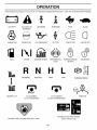
OP
ATION
These symbols may appear on your tractor or in literature supplied with the product,
BATTERY
CAUTION OR
WARNING
REVERSE
Learn and understand their meaning,
FORWARD
FAST
SLOW
CLUTCH
LIGHTS ON
LIGHTS OFF
DIFFERENTIAL
LOCK
PARKING BRAKE
LOCKED
"x___./
ENGINE ON
ENGINE OFF
FUEL
CHOKE
OILPRESSURE
MOWER HEIGHT
R N
REVERSE
MOWER L1FT
H
NEUTRAL
ATTACHMENT
CLUTCH ENGAGED
UNLOCKED
HIGH
LOW
ATTACHMENT
CLUTCH DISENGAGED
PARKING
IGNITION
HYDROSTATIC FREE WHEEL
(Hydro Models only)
DANGER, KEEP HANDS AND FEET AWAY
10
BRAKE
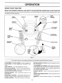
OPERATION
KNOW YOUR TRACTOR
READ THIS OWNER'S
MANUAL
AND SAFETY
RULES
BEFORE
OPERATING
YOUR
TRACTOR
C_mpare thei__ustrati_nswithy_urtract_rt_fami_iarizey_urse_fwiththe__cati_ns_fvari_usc_ntr__sandadjustments_
this manual for future reference.
CHOKE
IGNITION
SWITCH
AMMETER
CONTROL\
\
\
\
Save
\
THROTTLE
CONTROk_
\
CLUTCH/
BRAKE
PEDAL
HEIGHT
ADJUSTMENT
KN OB
FREEWHEEL
CONTROL
\
MOTION
CONTROL
LEVER
APPROX.
SPEED
3 MPH
2MPH
1MPH
FIG. 7
Our tractors conform to the safety standards of the American Natiorial Standards Institute.
ATTACHMENT CLUTCH LEVER: Used to engage the
mower blades, or other attachments mounted to your
tractor.
LIGHT SWITCH:
THROTTLE
MOTION CONTROL LEVER: Selects the speed and direction of the tractor.
ATTACHMENT LIFT LEVER: Used to raise and lower the
mower deck or other attachments mounted to your tractor.
LIFT LEVER PLUNGER: Used to release attachment lift
lever when changing its oosition.
Turns the headiigtqts on and off.
CONTROL:
Used to control engine speed.
CLUTCH/BRAKE PEDAL: Used fordeclutching
ing the tractor and starting the engine.
PARKING BRAKE:
brake position.
Locks clutch/brake
and brak-
IGNITION SWITCH:
engine.
pedal into the
HEIGHT ADJUSTMENT
cutting height.
FREEWHEEL CONTROL: Disengages transmisslor for
pushing or slowly towing the tractor with the engine off.
CHOKE CONTROL:
Used for starting and stopping the
AMMETER:
(-).
Used when starting a cold engine.
11
KNOB: Used to adjustthe mower
indicates battery charging (+) or discharglng
OP
RATION
The operation of any tractor can result in foreign objects thrown into the eyes, which can result
in severe eye damage. Always wear safety glasses or eye shields while operating your tractor
or performing any adjustments or repairs. We recommend a wide vision safety mask over the
spectacles or standard safety glasses.
i
i
i
HOW TO USE YOUR TRACTOR
TO USE THROTTLE
TO SET PARKING
Always operate engine at full throttle.
Operating engine at less than full throttle reduces the
9attery charging rate.
°
Fuf! throttle offers the best bagging and mower performance.
BRAKE
(See Fig, 8)
Your tractor is equipped with an operator presence sensing
switch.
When engine _s running, any attempt by the
operator to leave the seat without first setting the parking
brake will shut off the engine.
•
Depress clutch/brake pedal into full "BRAKE" position
and hold.
°
TO USE CHOKE
CONTROL
CONTROL
(See Fig. 8)
(See Fig. 8)
Use choke control whenever you are starting a cold engine.
Do not use to start a warm engine.
To engage choke contro[, oull knob out. Slowly push
knob n to disengage.
Place parking brake lever in "ENGAGED" position and
release p ressu re from clutchforake peda!. Pedal should
remain in "BRAKE" position. Make sure parking brake
will hold tractor secure.
TO MOVE FORWARD
Fig. 8)
AND BACKWARD
(See
The direction and speed of movement is controlled by the
motion control lever.
Start tractor with motion control lever in neutral (N)
position.
Release parking brake and clutch/brake pedal.
•
Slowly move motion control lever to desired position.
TO ADJUST
CLUTCH/BRAKE
PEDAL "DRIVE"
POSITION
'DISENGAGED"
POSITION
(See Fig, 8)
MOWER BLADES "
Move attachment clutch lever to "DISENGAGED" position.
GROUND DRIVE •
Depress clutch/brake pedal into full "BRAKE" position.
•
Move motion control lever to neutral (N) oosition:
IMPORTANT:
THE MOTION CONTROL LEVER DOES
NOT RETURN TO NEUTRAL (N) POSITION WHEN THE
CLUTCH/BRAKE PEDAL IS DEPRESSED.
ENGINE =
Move throttle control to slow (,_h) position.
NOTE: Failure to move throttle control to slow (,_1_.)
position and allowing eng ne to idle before stopping may
cause engine to "backfire",
•
Turn ignition key to "OFF" position and remove key.
Always remove key when leaving tractor to prevent
unauthorized use.
TO OPERATE
HEIGHT
CA"=-'-"=--'_TION:
Always stop tractor corn-
]
pletely, as described above, before leaving the operator s position; to empty
grass catcher, etc.
/
MOWER
(See Fig. 9)
Your tractor is equipped with an operator presence sensng switch. Any attempt by the operator to leave the seat
with the eng ne running and the attachment clutch engaged
will shut off the engine.
•
Select desired height of cut.
o
Lower mower with attachment lift control.
Start mower blades by engaging attachment clutch
control.
•
TO STOP MOWER BLADES - disengage attachment
clutch control.
Never use choke to stop engine.
NOTE: Under certain conditions when tractor is standing
idle With the engine running, hot engine exhaust gases may
cause "browning" of grass. To eliminate this oossibility,
always stop engine when stopping tractor on grass areas.
_
CUTTING
The cutting height is controlled byturning the height adjustment knob in desired direction.
Turn knob clockwise (('-_) to ratse cutting height.
*
Turn knob counterclockwise (_)to
lower cutting
height.
The cutting height range is approximately 1-1/2" to 4". The
heights are measured from the ground to the blade tip with
the engine not running. These heights are approximate
and may vary depending upon soil conditions, height of
grass and types of grass being mowed.
The average lawn should be cut to approximately 2-1/2
inches during the cool season and to over 3 inches
during hot months. For healthier and better looking
lawns, mow often and after moderate growth.
For best cutting performance, grass over 6 inches in
height should be mowed twice. Make the first cut
relatively high; the second to desired height.
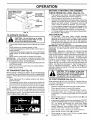
HEIGHT ADJUSTMENT
KNOB
FIG. 8
STOPPING
MOWER
(See Fig. 8)
CAUTION: Do not operate the mower
without either the entire grass catcher,
on mowers so equipped, or the discharge guard in place.
12
OPERATION
ATTACHMENT CLUTCH
LEVER "DISENGAGED"
POSITION
BEFORE STARTING
"ENGAGED"
POSITION
CHECK
ATTACHMENT
OIL LEVEL
(See Fig. 15)
-
HEIGHT
ADJUSTMENT
KNOB
The engine in your tractor has been shipped, from the
factory, already filled with summer weight oil.
o Check engine oil with tractor on level ground.
= Remove oil fill cap/dipstick and wipe clean, remsert the
dipstick and screw cad tight, wait for a few seconds,
remove anc read oil level. If necessary, add oil until
"FULL" mark on dipstick is reached. Do not overfill.
•
For cold weather operation you should change oil for
" easier starting (See "OIL VISCOSITY CHART" in the
Customer Responsibilities section of this manual).
o To change engine oil, see the Customer Responsibilities section in this manual
HIGH POSITION
DISCHARGE
GUARD
FIG. 9
TO OPERATE
ENGINE
THE ENGINE
ADD GASOLINE
ON HILLS
,
Fill fuel tank,
Use fresh, clean, regular unleaded
gasoline with a minimum of 87 octane. (Use of leaded
gasoline will increase carbon and lead oxide deposits
and reduce valve life). Do not mix oil with gasoline.
Purchase fuel in quantities that can be used within 30
days to assure fuel freshness.
IMPORTANT: WHEN OPERATING ]N TEMPERATURES
BELOW 32°F(0°C), USE FRESH, CLEAN WINTER GRADE
GASOLINE TO HELP INSURE GOOD COLD WEATHER
STARTING.
WARNING:
Experience indicates that aicohot blended
fuels (called gasohot or using ethanol or methanol) can
attract moisture which leads to separation and formation of
acids during storage. Acidic gas can damage the fuel
system of an engine while in storage. To avoid engine
problems, the fuel system should be emptied before storage of 30 days or longer. Drain the gas tank, start the
engine ant let it run until the fuel lines and carburetor are
empty. Use fresh fuel next season. See Storage Instructions for additional information.
Never use engine or
carburetor cleaner products in the fue! tank or permanent
damage may occur.
*
Choose the slowest speed before starting uu or down
hills.
°
Avoid stopping or changing speed on hills.
If slowing _snecessary, move throttle control lever to
slower position.
If stoppfng is absolutely necessary, push clutch/brake
pedal quickly to brake positior and engage parking
brake.
°
Move motion control lever to neutral (N) oosition.
IMPORTANT:
THE MOTION CONTROL LEVER DOES
NOT RETURN TO NEUTRAL (N) POSITION WHEN THE
CLUTCH/BRAKE PEDAL IS DEPRESSED.
,
TO restart movement, slowly release parking Icrake and
clutch/brake pedal.
°
Slowly move motion control lever to slowest setting.
,
Make all turns slowly.
TO TRANSPORT
(See Fig. 10)
When pushing or tow ng your tracto r, be sure to disengage
transmission by placing freewheel control in freewheeling
position. Free wheel control is located at the rear drawbar
of tractor.
Raise attachment lift to highest position with attachment lift control.
= Pull freewheel control knob out and hold in position by
inserting retainer spring into forward hole of control rod.
.
Do not push or tow tractor at more than two (2) MPH.
.
To reengage transmission, reverse above procedure.
NOTE: To protect hood from damage when transporting
your tractor on a truck or a trailer, be sure hood is closed
and secured to tractor, Use an appropriate means of tying
hood to tractor (rope, cord, etc.).
_i_
AlL,IlL
I
JD
I
i
spilled oil.or fueL Do not store, spilior
use gasoline near an open flame. _
TO START
ENGINE
(See Fig. 8)
When starting engine for the first time or if engine has run
out of fuel, it will take extra cranking time to move fuel from
the tank to the engine.
•
Depress c_utchibrake pedal and set parking brake.
•
Place gearshift Iever in neutral (N) position.
•
Move attachment clutch to "DISENGAGED"
position,
Pull choke control out to choke (\1) position for cold
eng ne start. For warm eng ne start do not use choke
control.
°
°
FIG; 10
CAUTION:
Fill to bottom of gas tank
filler neck. Donotoverfiil.
Wipeoffany
.
•
13
Move throttle control to midway between fast (._) and
slow (,_) positions.
Insert keyinto ignition and turn key clockwise to"START"
position and release key as soon as engine starts. Do
not run starter continuously for more than fifteen
seconds per minute. If engine does not start after
several attempts_ move throttle control to fast (,_)
position, wait a few minutes and try again.
When engine starts, slowly push choke control in.
Move throttle control to fast (,_) position_
Allow engine to warm up for a few minutes before
engaging drive or attachments.
OPERATION
NOTE: If at a high altitude (above 3000 feet) or in cold
temperatures (below 32°F), the carburetor fuel mixture
may need to be adjusted for best engine performance. See
"TO ADJUST CARBURETOR _'in the Service and Adjustments section of this manual.
-
!f grass is extremely tall. it should be mowed twice to
reduce load and possible fire hazard from dried clippings. Make first cut relatively high; the second to the
desired height.
PURGE TRANSMISSION
/"
i
_Never
&
engage or disengage-"-_
freewheelleverwhiletheengineisrun-
!
To ensureproper operation and performance, it is recommended that the transmission be purged before operating
tractor for the first time. This 3rocedure will remove any
trapped air inside the transmission which may have developed during shipping of your tractor.
IMPORTANT; SHOULD YOUR TRANSMISSION REQUIRE
REMOVAL FOR SERVICE OR REPLACEMENT,
IT
SHOULD BE PURGED AFTER REINSTALLATtON
BEFORE OPERATING THE TRACTOR
,
Place tractor safely on level surface with engine off and
3arking brake set.
Disengage transmission by placing freewheel control
n freewheeling positio_ (See "TO TRANSPORT" in
this sectron of "nanua0.
•
Sitting in the tractor seat, start engine. After the engine
s running, move throttle control to slow (-_1_.)position.
With motion control lever in neutral (N) position, slowly
disengage clutch/brake pedal.
Move motion control lever to full forward position and
hold for five (5) seconds. Move lever to full reverse
position and hold for five (5) seconds.
Repeat this
proceeure three [3) times.
NOTE: During this procedure there witl be no movement of
d rive wheels. The air is being removed from hydraulic drive
system.
Move motion control lever to neutral (N) position. Shutoff engine and set _arking brake.
•
Engage transmission by placing freewheel control in
driving position (See "TOTRANSPORT" in this section
of manual).
•
Sitting in the tractor seat, start engine. After the engine
is running, move throttle control to half (1/2) speed.
With motion control lever in neutral (N) position, slowly
disengage clutch/brake pedal.
•
Slowly move motion control lever forward, after the
tractor moves approximately five (5) feet. slowly move
motion control lever to reverse oosition.
After the
tractor moves approximately five (5) feet return the
motion control leverto the neutral (N) position. Reoeat
this procedure with the motion control lever three (3)
times.
•
Your tractor is now purged and now ready for normal
operation.
MOWING
TIPS
-
Tire chains cannot be used when the mower housing
,s attached to tractor.
=
Mower should be properly leveled for best mowing
3erformance. See "TO LEVEL MOWER HOUSING" in
the Service and Ad. ustments section of this manual•
The left hand side of mower should be used for trimming.
•
•
Drive so that
that has been
tractor. This
clippings and
clippings are discharged onto the area
cut Have the cut area to the right of the
will result in a more even distribution of
14
more uniform cutting.
When mowing large areas, start by turning to the right
so that clippings will discharge away from shrubs,
fences, driveways, etc. After one or two rounds, mow
in the opposite direction making left hand turns until
finished (See Fig. 11 ).
.
Do not mow grass when it is wet. Wet grass wil! plug
mower and leave undesirable clumps. Allow grass to
dry before mowing.
-
Always operate engine at full throttle when mowing to
assure better mowing performance and proper discharge of material. Regulate ground speed by selecting a low enough gear to give the mower cutting
performance as well as the quality of cut desired.
-
When operating attachments, select a ground speed
that will suit the terrain and give best performance of
the attachment being used.
F{G. 11
MULCHING
MOWING
TIPS
IMPORTANT:
FOR BEST PER=ORMANCE,
KEEP
MOWER HOUSING FREE OF BUILT-UP GRASS AND
TRASH. CLEAN AFTER EACH USE.
"
The special mulching blade will recut the grass clippings many times and reduce them in size so that as
they fall onto the lawn they will disperse into the grass
and not be noticed. Also, the mulched grass wili
biodegrade quickly to provide nutrients for the :awn.
Always mulch with your highest engine (blade) speed
as this wilt 3rovide the best recutting action of the
blades.
o Avoid cutting your lawn when it is wet. Wet grasstends
to form clumps and interferes with the mulching action.
The best time to mow your lawn is the early afternoon.
At this time the grass has dried and the newly cut area
will not be exposed to the direct sun.
•
For best results, adjust the mower cutting height so that
the mower cuts off only the top one4hird of the grass
blades (See Fig. 12). =or extremely heavy mulching,
reduce your width of cut and mow slowly.
Certain types of grass and grass conditions may require that an area be mulched a second time to
completely hide the clippings, When doing a second
cut. mow across or perpendicular to the first cut path.
o Change your cutting pattern from week to week. Mow
north to south one week then change to east to west the
next week. This will held prevent matting and graining
of the lawn,
MAX 113
FIG. 12
CUSTOM
MAINTENANCE
RESPONSIBILITIES
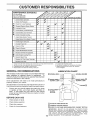
SCHEDULE
FILL IN DATES
AS YOU COMPLETE
REGULAR SERVICE
T
SERVICE
Check
Brake Operation
_
if
Check
Tire Pressure
!_
if
Check
for Loose Fasteners
Sharpen/Replace
Lubrication
Check
0
R
Mower
_'
Blades
......
,
$##'7 =
,
t[I/4
Chart
Battery Level/Recharge
Transaxle
if6
Cooling
11/_
'
I
I!/!
Replace
J
I
_
v'
i_1.2,3
i _2
q[/2
Arrester
v'
Oil Filter (if equipped)
N I Clean Engine Cooling
Replace Spark Plug
Fins
Replace
Air Filter Paper Cartridge
Replace
Fuel Filter
I
1 - Change
more
often
when
operating
_nder
a heavy
2 - Service
more
offer
when
operatirv,:j
in dirty
or dusbi
toad
or in high ambient
tempera[urea
conditions.
3 - If equipped with oil tilter change oil every 50 hours.
4 - Reelaceblades more often when mowing in sand_,soil
GENERAL
I
_#
Oii
Clean Air Screen
Inspect Muffler/Spark
|
I
,
Clean Air Filter
N
G,
I
1_'
Engine Oil Level
Engine
I
-
Adjust Motion Drive Belt(s) Tension
Change
.....
!_
Adjust Blade Belt(s) Tension
Check
, if
......
_
Clean Battery and Terminals
Check
.
DATES
5 - If equipped with adjustable system.
6 - Not requiredif equipped with maintenance-free battery.
7 - Tightenfront axle pivot heftto 35 ft.qbs, maximum,
Do not overiighten,
RECOMMENDATIONS
LUBRICATION
The warranty on this tractor does not cover items that have
been subjected to operator abuse or negligence.
To
receive full value from the warranty, operator must maintain
tractor as instructed in this manual.
Some adjustments will need to be made periodically
properly maintain your tractor.
_o
(_) SPINDLE
ZERK --
® BEARING
ZERK
CHART
ZERK(_
"FRONT WHEEL(_)
BEARING ZERK
Al! adjustments in the Service and Adjustments section of
this manual should be checked at east once each season.
ENGINE(_)
Once a year you should replace the spark plug, clean
or replace air filter, ann check blades and belts for
wear. A new spark plug and clean air filter assure
oroper air-fuel mixture and help your engine run better
and last longer.
BEFORE
O
CLUTCH
PIVOT(S)
EACH USE
Check engine oil level.
-
Check brake operadon.
•
Check tire pressure,
Check for loose fasteners,
15
Q
SAE 30 OR 10W30 MOTOR OIL
(_
GENERAL
(_
REFER TO CUSTOMER
PURPOSE GREASE
RESPONSIBILITIES
"ENGINE"
SECTION
IMPORTANT:
DO NOT OIL OR GREASE
THE PIVOT POINTS
WHICH HAVE SPECIAL NYLON BEARINGS.
VISCOUS
LUBRICANTS WiLL ATTRACT
DUST AND DIRT THAT WILL SHORTEN
THE LiFE OF THE SELF-LUBR}CATING
BEARINGS.
iF YOU
FEEL THEY MUST BE LUBRICATED,
USE ONLY A DRY, POWDERED GRAPHITE
TYPE LUBRICANT
SPARINGLY.
_-,
ii i
CUSTO
RESPONSIBILITIES
TRACTOR
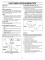
TO SHARPEN
Always observe safety rules when performing any maintenance.
Care should be taken to keep the blade balanced.
An
unbalanced blade will cause excessive vibration and eventual damage to mower and engine.
BRAKE
OPERATION
If tractor requires more than six (6) feet stopping distance
at high speed in highest gear, then brake must be adjusted.
(See "TO ADJUST BRAKE" in the Service and Adjustments section of this manual).
TIRES
•
Maintain proper air pressure in all tires (See "PRODUCT SPECIFICATIONS" on page 3 of this manual).
•
Keep tires free of gasoline, oil, or insect control chemicals which can harm rubber.
!
Avoid stumps, stones, deep ruts, sharp objects and
other hazards that may cause tire damage.
BLADE
{See Fig. 14)
-
The blade can be sharpened with a file or on a grinding
wheel. Do not attempt to sharpen while on the mower.
-
To check blade balance, you will heed a 5/8" diameter
steel bolt, pin, or a cone balancer. (When using a cone
balancer, follow the: instructions supplied with batancer).
*
Slide blade on to an unthreaded pc rtion of the steel bolt
or pin and hold the bolt orpin parallel with the ground.
If blade is balanced, it should remain in a horizontal
position. If either end of the blade moves downward,
sharpen the heavy end until the blade is balanced.
NOTE: Do not use a nail for balancing blade. The lobes of
the center hole may appear to be centered, but are not.
/
BLADE CARE
CENTER
For best results mower blades must be kept sharp.
place bent or damaged blades.
BLADE
REMOVAL
(See Fig. 13)
Raise mower to highest position to allow access to
blades.
e
Remove hex bolt, lock washer and flat washer secu ring
blade.
FtG. 14
Reassemble hex bolt, lock washer and flat washer in
exact order as shown.
i
BATTERY
°
Tighten bolt securely (30-35 Ft. Lbs. torque).
IMPORTANT: BLADE BOLT IS GRADE 8 HEAT TREATED.
Your tractor has a battery charging system which is sufficient for normal use. However, periodic charging of the:
battery with an automotive charger will extend its life.
NOTE: We do not recommend sharpening blade - bet ifyou
do, be sure the blade is balanced.
_"_
BLADE
5/8" BOLT
OR PIN
Install new or resharpened blade with trailing edge up
towards deck as shown.
BLADE
/
Re-
•.
o
HOLE
MANDREL
*
Keep battery and terminals clean.
,
Keep battery bolts tight.
o
Keep small vent holes open.
.
Recharge at 6-10 amperes for 1 hour.
TQ CLEAN BATTERY AND TERMINALS
_
Corrosion and dirt on the battery and terminals
the battery to "leak" power.
ASSEMBLY
can cause
Remove terminat guard.
TRAILING EDGE
,
FLAT WASHER
LOCK WASH_
,
Rinse the battery, with plain water and dry.
-
Clean terminals and battery
brush until bright.
-
coat terminals with grease or petroleum jelly.
HEX BOLT
(GRADE 8)*
",_._._=_._._._
Disconnect BLACK battery cable first
then RED
battery cable and remove battery from tractor.
cable ends with wire
Reinstall battery (See "CONNECT
Assembly section of this manual):
*A GRADE 8 HEAT TREATED BOLT CAN BE
IDENTIFIED BY SIX LINES ON THE BOLT HEAD,
FIG. 13
16
BATTERY"
in the
r,lnIJJ
"r
r ....
I I,
CUSTOMER
I
After oil has drained completely, replace oil drain plug
and tighten securely.
Check V-belts for deterioration and wear after 100 hours of
operation and replace if necessary. The belts are not
adjustable. Replace belts if they begin to slip from wear.
°
COOLING
The fan and cooling fins of transmission
clean to assure proper cooling.
, I
BILITIES
V-BELTS
TRANSAXLE
I,,
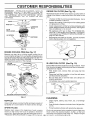
Refill engine with oil through oil fit! dipstick tube. Pour
slowly. Do not overfill. For approximate capacity see
"PRODUCT SPECIFICATIONS"
on page 3 of this
manual.
Use gauge on oil fill cap/dipstick for checking level. Be
sure dipstick cap is tightened securely for accurate
reading. Keep oi at "FULL" line on dipstick.
should be kept
Do not attempt to clean fan or transmission while engine is
running or while the transmissior is hot.
°
AIR SCREEN
/
OIL
DRAIN
PLUG
Inspect cooling fan to be sure fan blades are intact and
clean
Inspect cooling fins for dirt, grass clippings and other
materials. To prevent damage _o seals, do not use
compressed a_r or high pressure sprayer to clean
cooling fins.
TRANSAXLE
PUMP
OIL FILL
CAP/DIPSTSIC
FLUID
The transaxle was sealed at the factory and fluid maintenance is not rec uired for the life of the transaxle. Should the
transaxle ever leak or reauire servicing, contact your nearest authorized service center/department.
FIG. 15
CLEAN AIR SCREEN
ENGINE
Only use high quality detergent oil rated with API service
classification SF or SG. Select the oil's SAE viscosity grade
according [o your expected operating temperature.
AIR FILTER
t
0o
.20 _
-30 _
.20 °
TEMPERATURE
30°
.10 o
32° 40 °
0_
RANGE ANTICIPATED
"
60°
80°
10 _
BEFORE
20 °
Service air cleaner more often under dusty conditions.
100°
30 _
o
40_
NEXT OIL CHANGE
°
Slide foam pre-cleaner off cartridge.
•
Wash it in liquid detergent and water.
-
SQueeze it dry in a clean cloth.
Saturate it in engine oil. Wrap it in clean, absorbent
cloth and squeeze to remove excess oil.
Change the oil after the first two hours of operation and
every 25 hours thereafter or at least once a year if the
tractor is not used for 25 hours in one year.
Check the crankcase oil level before starting the engine
and after each eight (8) hours of operation, Tighten oil flit
cap/dipstick securely each time you check the oil level.
e
If very dirty or damaged, replace pre-cleaner.
e
Reinstall pre-cleaner over cartridge.
Reinstall cover and secure with knob(s).
TO SERVICE CARTRIDGE
e
®
TO CHANGE ENGINE 01L (See Fig. 15)
Determine temperature range expected before oil change.
All oil must meet API service classification SF or SG.
Be sure tractor is on level surface.
Oil will drain more freely when warm.
Catch oil in a suitable container.
•
Remove oil fit! cap/dipstick. Be careful not to allow dirt
to enter the engine when changing oil.
=
Remove drain plug.
Remove knob(s) and cover.
TO SERVICE PRE-CLEANER
NOTE: Althougn multi-viscosity oils (5W30, 10W30 etc.)
improve starting _n cold weather, these multi-viscosity oils
will result in increased oit consumption when used above
32°F. Check your engine oil level more frequently to avoid
possible engine damage from running ow o_ oil.
•
(See Fig, 16)
Your engine will not run properly using a dirty air filter.
Clean the foam pre-cleaner after every 25 hours of operation or every season. Service paper cartridge every 100
hours of operation or every season, whichever occurs first
SAE VISCOSITY GRADES
_C
(See Fig. 15)
Air screen must be kept free of dirt and chaff to prevent
engine damage from overheating. Clean with a wire brush
or compressed air to remove dirt and stubborn dried gum
fibers.
LUBRICATION
oF
K
17
Remove wing nuts and cartridge plate.
o
Carefully remove cartridge
entering carburetor.
to prevent
debris from
o
Clean cartridge by tapping gently on flat surface. If very
dirty or damaged, replace cartridge.
o
Reinstall cartridge plate, wing nuts, precleaner, cover
and secure with knob(s).
t,t011
LJ
CUSTOMER
....
RESPONSIBILITIES
IMPORTANT:
PETROLEUM
SOLVENTS,
SUCH
AS
KEROSENE,
ARE NOT TO BE USED TO CLEAK THE
CARTRIDGE
THEY MAY CAUSE DETERIORATION
OF
THE CARTRIDGE.
DO NOT OIL CARTRIDGE,
DO NOT
USE
uRESSURIZED
AIR
TO CLEAN
OR
DRY
CARTRIDGE,
ENGINE
,.,,..,
Unscrew old filter by turning counterclockwise.
suitable container to catch oil
°
AppJy a thin coating of new engine oil to rubber gasket
on replacement oil filter.
-
Install replacement oil filter by turning clockwise until
rubber gasket contacts mounting surface, then tighten
filter an additional 1/2 to 3/4 turn.
•
FilI crankcase with new oil (See "TO CHANGE ENGINE OIL" in this section of this manual). For approximate capacity see "PRODUCT SPECIFICATIONS" on
3age 3 of this manual.
-
Start engine and check for oil leaks. Correct any leaks
before placing engine into full operation.
AIR SCREEN
\
"CARTRIDGE
(See Fig. 18)
-
PLATE
FOAM
PRE-CLEANER
OiL FILTER
Replace the engine oil filter every season or every other oil
change if the tractor is used more than 100 hours n one
year.
Use a
FIG. 16
ENGINE
COOLING
FINS (See Fig. 17)
Remove any dust, dirt or eli from engine cooling fins to
prevent engine damage from overheating. Air guide covers
must be removed. Remove side panels and hood (See "TO
REMOVE HOOD AND GRILL ASSEMBLY" in the ServiCe
and Adjustments section of this manual).
IN-LINE
TOP AIR
GUIDE
FUEL FILTER
(See Fig. 19)
The fuel filter should be replaced once each season. If fuel
filter becomes clogged, obstructing fuel flow to carburetor,
replacement is required.
ENGINE
COOLING FINS
,
With engine cool, remove filter and plug fuel line
sections.
•
Place new fuel filter in position in fuel line with arrow
pointing towards carburetor.
Be sure there are no fuel line leaks and clamps are
properly positioned.
Immediately wipe up any spilled gasoline.
=
.
FUEL
/
FILTER AIR GUIDE COVER (BOTH
FIG. 17
\
_
//
/
---""--J
'
FIG. 19
CLEANING
MUFFLER
=
inspect and replace corroded muffler and spark arrester (if
equipped) as it could create a fire hazard and/or damage.
Clean engine, battery, seat, finish, etc. of all foreign
matter.
o
Keep finished surfaces and wheels free of all gasoline,
oil, etc.
SPARK
,
Protect painted surfaces with automotive
PLUGS
Replace spark plugs at the beginning of each mowing
season or after every 100 hours of operation, whichever
occurs first. Spark plug type and gap setting are shown in
"PRODUCT SPECIFICATIONS" on page 3 Ofthis manual. 18
type wax.
We do not recommend using a garden hose to clean your
tractor unless the electrical system, muffler, air filter and
carburetor are covered to keep water out. Water in engine
can result in a shortened engine life.
--
u
SERVICE
ADJUSTMENTS
CAUTION: BEFORE PERFORMING ANY SERVICE OR ADJUSTMENTS:
Depress cfutchlbrake pedal fully and set parking brake.
Place motion control lever in neutral (N) position.
Q
Place attachment clutch in "DISENGAGED"
position,
o
Turn ignition key "OFF" and remove key.
e
Make sure the blades and all moving parts have completely stopped,
o
Disconnect spark plug wire from spark plug and place wire where it cannot come in contact
with plug.
TRACTOR
TO REMOVE
CLUTCH
MOWER
(See Fig, 20)
=
Place attachment clutch in "DISENGAGED" position.
Move attachment lift lever forward to lower mower to its
Iowest eosition.
=
Roll belt off engine pulley,
•
Disconnect dutch rod from clutch lever by removing
retainer spring.
=
Disconnect anti-sway bar from chassis
removing retainer spring.
•
SPRING
CLUTCH ROD_
Mower will be easier to remove from the rig htside of tractor.
"_?_/,
bracket by
•
Disconnect front links from deck by removing retainer
springs,
-
Raise lift lever to raise suspension arms, Sride mower
out from under tractor.
'_"_
\ 4\
-
SPRING
ANTi-SWAY
(See Fig. 20)
o
Raise attachment
Iift Fever to its highest position.
•
Slide mower under tractor with discharge guard to right
side of tractor.
*
,
Lower lift Iever to its lowest position.
Install mower in reverse order of removal instructions,
"
/__E::_[
/
RETAINER
IMPORTANT:
IF AN ATTACHMENT OTHER THAN THE
MOWER IS TO BE MOUNTED TO THE TRACTOR.
REMOVE THE FRONT LINKS:
MOWER
RETAINER
ENGINE
FRONT
LINK
Disconnect suspension arms from rear deck brackets
oy removing retainer springs.
TO INSTALL
LEVER
/
BAR
t
RETAINER
SPRINGS
(BOTH SIDES)
FiG. 20
19
RETAINER
SPRINGS
(BOTH
SIDES)
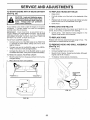
RVICE AN
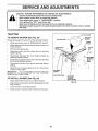
TO LEVEL
MOWER
HOUSING
FRONT-TO-BACK ADJUSTMENT (See Figs, 23 and 24)
IMPORTANT: DECK MUST BE LEVE_ SIDE-TO-SIDE. IF
THE FOLLOWING FRONT-TO-BACK ADJUSTMENT
IS
NECESSARY, BE SURE TO ADJUST BOTH FRONT LINKS
EQUALLY SO MOWER WILL STAY LEVEL SIDE-TOSIDE.
Adjust the mower while tractor is parked on level ground or
driveway.
Make sure tires are properly nflated (See
"PRODUCT SPECl FICATION S" on page 3 of this manual).
If tires are over or underinflated, you will not properly adjust
your mower.
SIDE-TO-SIDE
ADJUSTMENT
To obtain the best cutting results, the mower housing
should be adjusted so that the front is approximately 1/4" to
3/4" lower than the rear when the mower is in its nighest
posit_on.
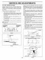
(See Figs. 21 and 22)
•
Raise mower to its qighest position.
°
At the midpoint of both sides of mower, measure height
from bottom edge of mower to ground, Distance "A" on
both sides of mower should be the same or within 1/4"
of each other,
,,
if adjustment is necessary,
side of mower only,
-
To raise one side of mower, tighten lift link adjustment
nut on that side.
°
To lower one side of mower, loosen lift link adjustment
nut on that side.
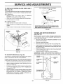
Check adjustment on right side of tractor, Measure distance "D" directly in front and behind the mandrel at bottom
edge of mower housing as shown.
o
Before making any necessary adjustments, check that
both front links are equal in length. Both links should be
approximately 10-3/8".
•
if inks are not equal n length, adjust one link to same
length as other link,
•
To lower front of mower loosen nut "E" on both front
Einksan equal number of turns.
•
When distance "D" is 1/4" to 3/4" lower at front than
rear, tighten nuts "F" against trunnion on both front
links.
•
To raise front of mower, loosen nut "F" from trunnion on
3oth front links. Tighten nut "E" on both front links an
equal number of turns.
When distance "D" is 1/4" to 3/4" lower at front than
rear. tighten nut"F" against trunnion on both front links.
°
Recheck side-to-side adjustment.
make adjustment on one
NOTE: Each full turn of adjustment nut will change mower
height about 1/8".
-
Recheck measurements
after adjusting.
BOTTOM EDGE
OF MOWER TO
GROUND
BOTTOM EDGE
OF MOWER TO
GROUND
/
MANDREL
GROUND LINE
\
FIG. 21
SUSPENSION
ARM
FIG. 23
BOTH FRONT LINKS MUST BE EQUAL
LIFT LINK
ADJUSTMENT
IN LENGTH
NUT
z
__:
,
FIG. 22
z \'S
NUT "E"
NUT "F"
/l
FRONT LINKS
20
TRUNNION
FIG. 24
....................................
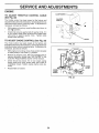
SERVICE AN
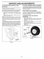
TO REPLACE
(See Fig. 25)
MOWER
BLADE
DRIVE
i-u
i
ADJUSTMENTS
BELT
The mower blade drive belt may be replaced without tools.
Park the tractor on level surface. Engage parking brake.
BELT REMOVAL •
Remove mower from tractor (See "TO REMOVE
MOWER" in this section of this manual).
•
Work belt off both mandrel pulleys ana idler pulleys.
,
Pull belt away from mower.
BELT INSTALLATfON
-
ARM
-
Install new belt in reverse order of removal.
•
Make sure belt is in atl pulley grooves and inside all belt
guides.
Install mower in reverse order of removal instructions.
•
DO NOT TOUCH THIS NUT, IF FURTHER BRAKE ADJUSTMENT IS NECESSARY CONTACT YOUR NEAREST AUTHORIZED SERVICE CENTER/DEPARTMENT
FIG. 26
MANDREL
PULLEY
IDLER
PULLEYS
TO REPLACE
(See Fig. 27)
MOTION
DRIVE
BELT
Park the tractor on level surface. Engage parking brake.
For assistance, there is a belt installation guide decal on
bottom side of left footrest.
-
Remove mower (See "TO REMOVE MOWER" in this
section of this manual.}
•
Remove upper belt keeper.
•
Remove belt from stationary idler and clutching idler.
-
Pult belt slack toward rear of tractor. Carefully remove
belt upwards from transmission input pulley and over
cooling fan blades.
Pull belt toward front of tractor and remove downward
from around engine pulley.
\\
-
MANDREL
PULLEY
Install new belt by reversing above procedure.
IMPORTANT:
MAKE SURE UPPER BELT KEEPER IS
POSITIONED PROPERLY BETWEEN LOCATOR TABS.
FIG. 25
TO ADJUST
BRAKE
(See Fig. 26)
Your tractor is equipped with an adjustable brake system
which is mounted on the side of the transaxle.
ENGINE-,--,___II
PULLEY
_"--_,_,,_,,_ ._
If tractor reoutres more than six (6) feet stopping distance
at high speed in highest gear. then brake must be adjusted,
CLUTCH
-
Depress clutch/brake pedal and engage parking brake.
-TATI--NARY-_
o
Measure distance between brake operating arm and
nut "A" on brake rod.
tf distance is other than 1-3/4", loosen jam nut and turn
nut "A" until distance becomes 1-3/4". Retig hten jam
nut against nut "A'.
_'_T{_,
_
""
_:-_--_|
?dLER
°
Road test tractor for proper stopping distance as stated
above. Readjust if necessary. If stopping distance is
still greater than s_x (6) feet in highest gear, further
maintenance is necessary. Contact your nearest authorized service center!department.
TRANSMISSION
21
LOCATOR
UPPER BELT
KEEPER
-H,.._P
.,...."-_r!
FIG, 27
CE AND ADJUSTMENTS
i
TO ADJUST
MOTION
CONTROL
LEVER
i
TO ADJUST
(See Fig. 28)
i
STEERING
WHEEL
ALIGNMENT
The motion control lever has been preset at the factory and
adjustment should not be necessary.
if steering wheel crossbars are not horizontal (left to right)
when wheels are positioned straight forward, remove steering wheel and reassemble per instructions in the Assembly
section of this manual.
ff for any reason the motion control lever will not hold its
oosition while at a selected speed, it may be adjusted atthe
friction pack located on the right side of transmission.
FRONT WHEEL
•
Park tractor on level surface. Stop tractor by turning
ignition Key to "OFF" position, and engage parking
brake
•
Adjust motion control Iever by tightening adjustment
Iocknut one half [1/2_ turn
The front wheel toe-in and camber are not adjustable on
your tractor, tf damage has occurred to affect the front
wheel toe-in or camber, contact your nearest authorized
service center/de 3artment.
TO REMOVE WHEEL FOR REPAIRS
(See Fig. 29)
NOTE: If for any reason the effort to move the motion
control lever becomes too excessive, reverse the above
adjustment procedure by loosening Iocknut 1/4 to 1/2 turn.
•
-
Road test tractor after adjustment and repeat orocedure if
necessary.
TRANSMISSION
TOE-IN/CAMBER
,
•
REMOVAL/REPLACEMENT
Should your transmission require removal for service or
replacement, it should be purged after reinstailation and
before operating the tractor. See "PURGE TRANSMISSION" in the Operation section of this manual.
•
•
Block up axle securely.
Remove axle cover, retaining rrng and washers to allow
wheel removal (rear wheel contains a square key - Do
not lose).
Repair tire and reassemble.
On rear wheels only: align grooves _n rear wheel hub
and axle. Insert square key.
Replace washers and snap retaining ring securely in
axle groove.
Replace axle cover.
WASHERS
RETAINING
RING
\
\
I
\
AXLE COVER
_-_"
SQUARE
KEY
(REAR WHEEL
FIG. 29
ADJUSTMENT
LOCKNUT
FIG. 28
22
ONLY)
SERVICE
TO START ENGINE
See Fig. 30)
.
_
WITH A WEAK
_
AND ADJUSTMENTS
BATTERY
-
TO REPLACE
-
Pull bulb holder out of the hole in the backside of the
grill.
•
Replace bulb in holder and push bulb holder securely
back into the hole in the backside of the grill.
Close hood.
°
INTERLOCKS
If your battery is too weak to start the engine, it should be
recharged,
If "jumper cables" are used for emergency
starting, follow this procedure:
•
TO REMOVE
=
Raise hood.
HOOD
AND GRILL
ASSEMBLY
•
Unsnap headlight wire connector.
=
Stand in front of tractor. Grasp hood at sides, tilt toward
engine and lift off of tractor.
-
To replace, reverse above procedures.
TQ REMOVE CABLES. REVERSE ORDER BLACK cable first from chassis and then from the fully
charged battery.
RED cable tast from both batteries.
HOOD
P
"NEGATIVE"
FUSE
(See Fig. 31)
Connect the other end of the BLACK cable to good
CHASSIS G ROUND, away from fuel tank and battery.
(+)
in the
Replace with 30 amp automotive-type plug-in fuse. The
fuse holder _s ocated behind the dash.
Connect each end of the RED cable to the POSITIVE
(+) terminal of each battery, taking care not to short
against chassis.
Connect one end of the BLACK cable to the NEGATIVE (-) terminal of fully charged battery.
"POSITIVE"
Check wiring. See electrical wiring diagram
Reoa_r Parts section of this manual.
TO REPLACE
TO ATTACH JUMPER CABLES -
,
AND RELAYS
Loose or damaged wiring may cause your tractor to run
poorly, stop running, or prevent it from starting.
IMPORTANT:
YOUR TRACTOR
US EQUIPPED WITH A
12 VOLT NEGATIVE GROUNDED
SYSTEM. THE OTHER
VEHICLE
MUST
ALSO
BE A 12 VOLT
NEGATIVE
GROUNDED
SYSTEM.
DO NOT USE YOUR TRACTOR
BATTERY TO START OTHER VEHICLES.
°
BULB
Raise hood.
=
ateexplosive gases. Keep sparks, flame
and
smokingLead-acid
materials batteries
away from
batCAUTION:
generteries.
Always wear eye protection
when around batteries.
-
HEADLIGHT
-
/
/
HEADLIGHT
WIRE
CONNECTOR
(-)
L.H. PANEL
BOLT
FIG. 31
FIG. 30
23
SERVICE AND ADJUSTMENTS
"--7
ENGINE
CLAMP SCREW
TO
ADJUST
THROTTLE
CONTROL
CABLE
/
(See Fig. 32)
f
QUARTER
The throttle control has been preset at the factory and
adjustment should not be necessary. Check adjustment as
described below before loosening cable. If adjustment _s
necessary, proceed as follows:
-
With engine not running, move throttle control lever to
fast (,_) position.
°
Check that swivel is against side of quarter circle. If it
s not, loosen cable clamo screw and putl cable back
until swivel is against quarter circle. Tighten cable
clamp screw securely.
CIRCLE
t
_
.S ....
\\.,..
Ill
_>
SWIVEL
TO ADJUST
CHOKE
CONTROL
(See Fig. 33)
The choke control has been preset at the factory and
adjustment should not be necessary. Check adjustment as
described below 3efore loosening cable. If adjustment is
necessary, proceed as follows:
•
With engine not running, move choke control (located
on dash panel) to fult choke (f\t) position.
-
Remove air cleaner cover, filter and cartridge plate to
expose carburetor choke (see "AIR FILTER" in the
Customer Responsibilities section of this manual).
°
Choke should be ctosed, If it is not, Foosen casing
clamp screw and move choke cable until choke is
completely closed. Tighten casing clamp screw _ecurely.
Reassemble air cleaner.
°
FIG. 32
~CHOKE
LEVER
CLAMP
SCREW
FIG. 33
24
SERVICE
TO ADJUST
CARBURETOR
(See Figs.
ADJUSTMENTS
IMPORTANT:
NEVER
TAMPER
WITH
THE ENGINE
GOVERNOR,
WHICH IS FACTORY
SET FOR PROPER
ENGINE SPEED, OVERSPEEDING
THE ENGINE ABOVE
THE
FACTORY
HIGH
SPEED
SETTING
CAN
BE
DANGEROUS,
IF YOU THINK THE ENGINE-GOVERNED
HiGH SPEED NEEDS ADJUSTING,
CONTACT
YOUR
NEAREST
AUTHORIZED
SERVICE
CENTER/
DEPARTMENT,
WHICH HAS PROPER EQUIPMENT
AND
EXPERIENCE
TO
MAKE
ANY
NECESSARY
ADJUSTMENTS.
34 &
35)
The carburetor has been preset at the factory and adjustment should not be necessary, However, minor adjustment may be required to compensate for differences in fue!
temperature, altitude or load. tf the carburetor does need
adjustment, proceed as follows:
In general, turning the mixture screw in (clockwise) decreases the supply of fuel to the engine giving a leaner fuel/
air mixture. Turning the mixture screw out (counterclockwise) increases the supply of fuel to the engine giving a
richer fuel/air mixture.
IMPORTANT:
DAMAGE TO THE NEEDLES AND THE
SEATS IN CARBURETOR MAY RESULT IF SCREW IS
TURNED tN TOO TIGHT.
PRELIMINARY
=
•
IDLE SPEED
SCREW
SETTING -
IDLE MIXTURE
SCREW
Be sure you have a clean air filter, and the throttle
control cable and choke are adjusted properly (see
above).
THROTTLE
LEVER
With engine off turn idle mixture screw in (clockwise)
closing it finger tight and then turn out (counterclockwise) 1-t/4 to 1-1/2 turns.
FINAL SETTING o
Start engine and allow to warm for five minutes. Make
final adjustments with engine running and shifb_motion
control lever in neutral (N) position.
iii o
With throttle control lever in slow (,_Jl) position, hold
throttle lever against idle speed screw and adjust idle
speed screw to obtain 1200 to 1400 RPM.
-
While still holding throttle lever against idle speed
screw, turn idle mixture screw in (clockwise) until
engine begins to die and then turn out (counterclockwise) until engine runs rough. Turn screw to a point
midway between those two positions.
-
Continue to hold throttle lever against idle speed screw
and adjust idle speed screw to obtain 900 to 1200
RPM. Release throttle lever.
!:
ACCELERATION
-
FIG, 34
THROTTLE
TEST -
IDLE MIXTURE
SCREW
LEVER
Move throttle control lever from slow (,!_) to fast (,_)
position. If engine hesitates or dies. turn idle mixture
screw out (counterclockwise)
1/8 turn. Repeat test
and continue to adjust, if necessary, until engine accelerates smoothly.
High speed stop is factory adjusted.
damage may result.
\
'_
FIG. 35
Do not adjust -
25
STORAGE
=
ENGINE
Immediately prepare your tractor foi" storage at the end of
the season or if the tractor will not be used for 30 days or
more.
FUEL SYSTEM
IMPORTANT:
IT S IMPORTANT
TO PREVENT
GUM
DEPOSITS
FROM
FORMING
IN ESSENTIAL
FUEL
SYSTEM PARTS SUCH AS CARBURETOR,
FUEL FILTER,
FUEL HOSE, OR TANK DURING
STORAGE.
ALSO,
EXPERIENCE
INDICATES
THAT ALCOHOL
BLENDED
FUELS (CALLED
GASOHOL
OR USING
ETHANOL
OR
METHANOL)
CAN ATTRACT MOISTURE
WHICH LEADS
TO SEPARATION
AND FORMATION
OF ACIDS DURING
STORAGE.
ACIDIC
GAS CAN DAMAGE
THE FUEL
SYSTEM OF AN ENGINE WHtLE N STORAGE.
gasoline in the tank inside a building
where
fumesNever
may store
reachthe
an tractor
open flame
CAUTION:
with
or spark.
Allow the engine to cool
before storing in any enclosure,
TRACTOR
Remove mower from tractor for winter storage. When
mower rs to 3e stored for a period of time. clean it thoroughly, remove all dirt, grease, leaves, etc. Store in a
clean, dry area.
•
Clean entire tractor (See "CLEANING" in the Customer
Responsibilities section of this manual).
•
Inspect and replace belts, if necessary _See belt replacement instructions in the Service and Adjustments
section of this manual).
Drain the fuel tank.
o
Start the engine and let it run until the fuel lines and
carburetor are empty.
-
Never use engine or carburetor cleaner products in the
fuel tank or permanent damage may occur.
Use fresh fuel next season.
•
NOTE:
Fuel stabilizer is an acceptable alternative in
minimizing the formation of fuel gum deposits during storage. Add stabilizer to gasoline in fuel tank or storage
container. Always follow the mix ratio found on stabilizer
container. Run engtne a_ least 10 minutes after adding
stabilizer to allowthe stabilizer to reach the carburetor. Do
not drain the gas tank and carburetor if using fuel stabilizer.
Lubricate as shown in the Customer Responsibilities
section of this manual.
!
-
Be sure that all nuts, bolts and screws are securely
fastened. Inspect moving parts for damage, breakage
and wear. Replace if necessary.
ENGINE
Touch up all rusted or chipped paint surfaces: sand
lightly before painting.
OIL
Drain oil (with engine warm) and replace with clean engine
oil. (See "ENGINE" in the Customer Responsibilities
section of this manual).
BA'I-rERY
Fully charge the battery for storage.
CYLINDERS
After a oeriod of time in storage, battery may require
recharging.
-
Remove spark plug(s).
To help prevent corrosion and power leakage during
long periods of storage, battery cables should be
disconnected and battery cleaned thoroughly (see "TO
CLEAN BATTERY AND TERMINALS'
in the Customer Responsibilities section of this manual).
-
Pour one ounce of oil througn spark plug hole(s) into
cylinder(s).
-
Turn ignition key to"START" position for a few seconds
to distribute oil,
After _cleaning, leave cables disconnected and place
cables where they cannot come in contact wfth battery
terminals.
•
Replace with new spark plug(s).
•
Be sure battery drain tube is securely attached.
=
Do not store gasoline from one season to another.
-
If battery is removed from tractor for storage, do not
store battery directly on concrete or damp surfaces.
-
Replace your gasoline can if your can starts to rust.
Rust and/or dirt i_ your gasoline wil cause problems;
*
If possible, store your tractor indoors
give protection from dust and dirt.
OTHER
-
ane cover it to
Cover your tractor with a suitable protective cover that
does not retain moisture. Do not use plastic. Plastic
cannot breathe which allows conden sation to form and
will cause your tractor to rust.
IMPORTANT: NEVER COVER TRACTOR WHILE ENGINE
AND EXHAUST AREAS ARE STILL WARM.
26
TROU
=-
=
.
PROBLEM
Will not start
Hard tostart
Engine will not turn over
Engine
start
ESHOOTI
-
clicks but will not
Loss of power
POINTS
----
CAUSE
__
CORRECTION
1.
Out of fuel.
2
3
4
5.
6.
7
Engine not "CHOKED"
Engine flooded.
Sad spark pIug.
DJrty air filter.
Dirty fue! fiffer
Water in fuel.
1
Fill fuel tank.
properly,
2
3
4
5.
6.
7.
8
9
10.
_oose or damaged wiring.
Carburetor out of adjustment.
Engine vatves out of adjustment.
8.
9.
10,
See "TO START ENGINE" in Operation section.
Wait several minutes before attempting to start.
Replace spark ptug,
CJean/re_Iace air filter,
Replace fuel fiitar,
Drain fuel tank and carburetor, refill tank with fresh
gasoline and replace fuel filter.
Check all wiring.
Contact an authorized service centeddepartment.
Contact an authorized service center/department.
1
2,
3.
4.
5.
6.
7.
8.
Dirty air _ter.
Sad spark plug.
Weak or dead battery,
Dirty' fuel filter,
State or dirty fuel.
Loose or damaged wiring.
Carburetor out of adjustment.
Engine valves out of adjustment.
1.
2.
&
4.
5.
Clean/replace air filter.
Replace spark plug.
Recharge or replace battery.
Replace fuel fi_ter.
Drain fuel tank and refill with fresh gasoline.
6.
7.
8.
Check at_wiring.
Contact an authorized
Contact an authorized
_.
2.
3.
4.
Cfutchibrake pedal not depressed
Attachment clutch s engaged.
Weak or dead battery.
Blown fuse.
1.
2,
3,
4.
Depress clutch/brake pedal
Disengage attachment dutch,
Recharge or replace battery.
Replace fuse,
5.
6.
7.
8.
9.
Corroded battery terminals.
Loose or damaged wiring.
Faulty ignition switch
Faulty solenoid or starter_
Faulty operator presenceswitchles).
5.
6,
7.
8.
9.
Clean battery terminals.
Check all wiring,
Check/replace ignition switch,
Check/replace solenoid or starter.
Contact an authorized service center/department,
1.
2.
3.
4.
Weakor dead battery.
Corroded battery terminals.
Loose or damaged wiring.
Faulty solenoid or starter.
t.
2.
3.
4.
Rechargeor replace battery.
Clean battery terminals.
Checkal] wiring,
Check2replaceso]enoid
or starter.
1.
2.
3
4
5
6.
7.
8.
9.
Cutting too much grass/too fast.
Throttle in "CHOKE" position.
8uitd-up of grass, leaves and trash under mower,
Dirty air filter.
Low oil leveltdirty oil.
Faulty spark plug.
Dirty fuel filter.
Stale ordirty rue
Water in fuel
1.
2.
3,
4.
5,
6.
7.
8.
9.
Set in"Higher Cut" position/reduce
speed.
Adiust throttle control.
Clean underside of mower housing.
Clean/replace air filter.
Checkoil level/change oil,
Clean and regap or change spark plug,
Replace fuet fitter,
Drain fuet tank and refill with fresh gasoline,
Drain fueI tank and carburetor, refitl tank with fresh
10.
11.
12,
13.
14
]5.
Spark plug wire ioose.
Dirty engine a_r screen/fins,
Dirty/clogged muffler.
Loose or damaged wiring,
Carbu rotor out of aa;ustment.
Engine valves out of adjustment.
vibration
I.
2.
Worn. 3ent or loose blade.
Bent blade mandrel
3.
Loose/damaged
1.
2.
3.
part(s),
27
service center/department.
service center/department.
gasoline and reelace fuel filter.
Connect and tighten spark plug wire.
Clean eng ne a_r screen/fins
Clean/replace muffler,
Check aliwiring,
Contact an authorized service center/department.
Contact an authorized service center/department.
10.
11,
12,
!3,
14.
15.
......
Excessive
-.
. .=
Replace btade T ghten bFade bolt.
Replace blade mandrel.
Tighten Ioose,oartis).
Reelace damaged
parts,
m
==,=
'
m
......
TROUBLESHOOTING
......
PROBLEM
=
CAUSE
POINTS
,
CORRECTION
=
Engine continues to run
when operator leaves seat
with attachment clutch
engaged
].
Poor grass discharge
Faulty operator-safety
presence controf system.
1.
__
Check wiring, switches and connections,
ff not
corrected, contact an authorized service center/
department
Poor cut - uneven
Mower blades will not
rotate
m
2.
Worn, bent or loose blade.
Mowerdeck nozlevel.
1.
2.
Replace blade. Tighten blade bolt.
Level mower deck.
3.
4.
Buildup of grass, {eaves, and trash under mower,
Bent blade mandre
5,
Clogged mower deck vent holes from buildup of
grass, leaves, and trash around mandrels,
3.
4.
5.
Clean underside of mower housing.
Replace blade mandrel.
Clean around mandrels _o open vent holes.
1.
Obstruction
2.
3.
4.
Worn!damaged mower drive belt.
Frozen idlerpu]ley.
Frozen blade mandrel
1.
2.
Remove obstruction
Replace mower drive belt,
3.
4
Replace idler pulley,
Replace blade mandrel,
1.
Engine speed too slow.
Travel speed too fast
Wet grass.
Mower deck not level.
1.
2.
3
4.
Place throttle control in "FAST" position
Shift to slower speed.
Allow grass to dry before mowing.
Level mower decK.
2.
3.
4.
5.
6.
7.
8.
9.
10.
11.
in clutch mechanism.
Low/uneven tire air pressure.
Worn. bent or toose blade.
Buildup of grass, leaves and trash under mower.
Mower drive belt worn.
Blades impropeny installed.
Improper blades used.
C{ogged mower deck vent holes from buitdun of
grass, leaves and trash around mandrels,
5.
6,
7.
8
9
10
1t
Check tires for proper air pressure.
Replace/sharpen blade, Tighten blade bolt,
Clean underside of mower housing.
Replace mower drive belt.
Reinstall blades sharp edge down
Replace with blades listed n this manual.
Clean ground mandrels to open vent holes
1,
Switch is "OFF",
1
Turn switch "ON"
2.
3.
4.
5,
Bulb(s) burned out.
Fautty light switch.
Loose or damaged wiring,
Blown fuse.
2
3,
4.
5.
Reptace bulb(s).
Checldreplace fight switch.
Check wiring and connections.
Replace fuse.
1.
2.
Bad battery cell(s).
Poor cable connections.
1
2.
Replace battery,
Check/clean allconnections,
3.
4.
Faulty regulator (if so equipped).
Faulty alternator,
3.
4
Replace regulator.
Replace alternator.
Loss of drive
1,
2.
3,
Freewheel control in"disengaged"
position.
Motion drive belt worn. uamaged, or _ roken,
Air trapped in transmission during shipment
or servicing,
1
2.
3,
Place freewheeI control Jn"engaged"
Replace motion drive belt
Purge transmission,
Engine "backfires"
when turning engine
"OFF"
1.
Engine throttle control not set at "SLOW"
position for 30 seconds before stopping engine,
Headlight(s) not working
(if so equipped)
Battery will not charge
28
position.
Move throttle control to "SLOW" position and allow
to idle for 30 seconds before stopping engine.
TRACTOR
- - MODEL NUMBER
917.256571
SCHEMATIC
RED
BLACK
BATTERY
RED
CF_
l
RED
FUSE 30 AMP.
AMMETER
t_
STARTER
BLACK
O',O
WHITE
......
J
SOLENOID
J
dUTCH/ BRAKE
(PEDAL
UP)
WHITE
IGNITION SWITCH
....
(NOT OCCUPIED)
____
SEAT
J w""E:o-
SWITCH
;r-o,
_LACK
BLACK
CONNECTOR
A
,ON,T,ONsPARK
--'
BLACK
UNIT
PLUGS
CHARGING SYSTEM OUTPUT
3 AMP DC @ 3600 RPM
\
28 VOLTS AC MIN. @ 3600 RPM
/CHARGING
SYSTEM DISCONNECTFD}
/
RED
UGHTING
SYSTEM
OUTPUT
DIODE
ALTERNATOR
5 AMP AC @ 3600 RP.,.MM_
POSITION
CIRCUIT
OFF
ON
M + G
B+L
START
B + S + L
O
NOTE
YOUR TRACTOR IS
EQUIPPED WITH A SPECIAL
ALTERNATOR SYSTEM.
THE LIGHTS ARE NOT
CONNECTED TO THE
BATTERY, BUT HAVE THEIR
OWN ELECTRICAL SOURCE
BECAUSE OF THIS. THE
BRIGHTNESS OF THE LIGHTS
WILL CHANGE WiTH ENGINE
SPEED. AT IDLE THE LIGHTS
WILL DIM. AS THE ENGINE IS
SPEEDED UP, THE LIGHTS
WILL BECOME THEIR BRIGHTEST,
NON-REMOVABLE
CONNECTIONS
REMOVABLE
CONNECTIONS
29
14 VOLTS AC M_N @ 3600 RPM (LIGHTS
OFF)
HEADLIGHTS
(OFF)
/_
WIRING INSULATED CLIPS
NOTE: tF WIRING INSULATED
CLIPS WERE REMOVED FOR
SERVICING OF UNIT THEY
SHOULD BE REPLACED TO
PROPERLY SECURE YOUR WIRING.
REPAIR PARTS
TRACTOR
- - MODEL NUMBER
917.256571
ELECTRICAL
22
21
f/
7O
I
16
2O
/
25
t
l
REPAIR PARTS
TRACTOR
- - MODEL NUMBER
917.256571
ELECTRICAL
KEY
NO.
1
2
3
PART
NO,
6
7
8
9
10
11
12
16
19
20
21
22
24
25
26
28
29
30
31
32
33
36
38
39
146140
74760412
STD551025
STD551125
STD541025
7697J
7603J
109596X
145211
145209
145769
153664
STD551125
73350400
147430
4152J
4206J
146148
108824X
145491
121305X
140301
12421tX
141226
109310X
STD601005
140336
109553X
40
41
42
43
44
45
52
55
70
151212
71110408
131563
145673
73640400
121433X
141940
17490508
140712
NOTE:
DESCRIPTION
Battery
Bolt, Hex 1/4-20 x 3/4
Washer 9/32 x 5/8 x 16 Gauge
Washer, Lock 1/4
Nut, Hex 1/4-20
Tube
Tray, Battery
Clamp, Hose
Bolt, Btr Front 1/4-20 x 7-1/2
Holddown Battery Dash Mount
Nut, Push Nylon Battery Front 1/4
Switch Interlock Push-It
Washer. Lock 1/4
Nut, Hex, Jam 1/4-20
Harness, _ight Socket (w!4152J)
Light Bulb
Cable, Battery
Cable, Battery
Fuse
Cable, Ground
Switch, Seat
Switch, Ignition 4 Position
Nut, Ignition
Cover, Ignition Switch
Key, Molded, Craftsman
Screw, Hex. Tapping #10-24 x 1/2
Bracket. Switch Interlock
Switch, Interlock. Attachment
Clutch
Harness, Ignition
Bolt BIk Fin Hex 1/4-20 UNC x 1/2
Cover, Terminal
Solenoid
Nut Keps Blk Hex 1/4-20 UNC
Ammeter Rectangular 6 Amp
Protection Wire Loop (Hour Meter)
Screw Thdrol 5/16-18 x 1/2
Harness Engine LT Private Label
Aft component dimensions
t inch = 25.4 mm
31
given in U.S. inches
REPAIR PARTS
TRACTOR
CHASSIS
- -MODEL
NUMBER
917.256571
AND ENCLOSURES
24
3O
28
\
J
58
12
25
53
26
14
6
26
6O
33
10
14
26
3
32
REPAIR PARTS
TRACTOR-CHASSIS
MODEL NUMBER
917.256571
AND ENCLOSURES
KEY
NO.
PART
NO.
151169
140356
17490612
1
2
3
4
5
6
8
9
10
11
12
13
14
STD551025
146077
145206
126471X
147633X010
STD533710
146956
145660
146962
17490608
15
74180512
16
17
20
23
24
STD541431
144983X574
145210
124028X
STD523710
25
26
19131312
STD541437
28
29
30
31
33
34
35
37
38
145198X459
145199
140002X574
137113
145244X574
145243X574
STD533707
17490508
139886
39
139887
44
47
51
52
53
54
140675
I05531X
73800400
19091416
145201
17030814
55 145202
57 STD552507
58 140547
74 STD541437
140 150556
NOTE:
DESCRIPTION
Chassis
Drawbar
Screw. Thd.. Roll. 3/8-16 x 3/4 Type
TT
Washer 13/32 x 3/4 x 16 Gauge
Bumper Snap-in
Saddle
Clip, Fuel Line
Dash. Silkscreened
Bolt, Carriage 3/8-16 x 1
Pane[, Dash, LH
CI fp Tinnerman Grille P/L
Panel. Dash, RH
Screw, Thd., Roll. 3/8-16 x 1/2 Type
TT
Screw Machine, Thd,, Roll.
5/16-18 UNC x 3/4
Nut. Hex, Keps 5/16-18 UNC
Hood Assembly
Plate Mtg Battery Fuel Tank 95
Bushing, Snap, Nylon, Fuel Line
Bolt, Hex Head, Fin.
3/8-16 UNC x 1 Grade 5
Washer 13/32 x 13/16 x 12 Gauge
Locknut Hex, with Insert 3/8-16 UNC
Grille, W/Clips MS-459
Lens. Gritle
Fender
Bracket, Fender
Footrest. LH
Footrest, RH
BoIL Carriage 3/8-16 x 3/4
Screw. Thdrol. 5/16-18 x 1/2 TYT
Pivot Bracket Assembly, LH, Mower,
Rear
Pivot Bracket Assembly, RH, Mower
Rear
Strap Assembly, Fender
Nut. Push. Nylon
Nut Lock W/Insert 1/4 - 20 UNC
Washer 9/32 X 7/8 X 16 Ga.
Bracket Grille Oickoff LH
Screw, Hex Head, Spiderlock #8 x 7/8
AB
Bracket Grille Pickoff RH
Bolt FinHex 1/4 -20 UNC X.75
Air Duct P/L 18HP B&S Opp. Twin
Nut Crownlock 3/8-16 UNC
Bracket Chassis Front
All component dimensions given in U.S. inches
inch = 25.4 mm
33
REPAIR PARTS
TRACTOR
-- MODEL NUMBER
917.256571
DRIVE
57
86
10
45
19
36
96
53
95
98
30
61
\
•78
75
34
_6o
55
106
/
REPAIR PARTS
TRACTOR
- - MODEL NUMBER
917.256571
DRIVE
KEY
NO.
PART
NO.
1
2
3
8
10
15
16
18
19
21
22
24
25
26
27
28
29
30
3t
32
34
35
36
37
38
39
40
41
42
44
45
46
47
48
49
50
51
52
53
55
56
57
150071
142431
143995
141002
STD561210
74490544
STD541431
STD523710
STD541437
130564
145627
73350600
106888X
STD551037
STD5612t0
145204
124236X
130807
127275X
74760512
151128
120183X
19211616
t572H
123674X
STD523727
4470J
153399
19131312
105706X
1108!2X
12000039
127783
123789X
123205X
STD523715
STD541437
STD541431
105710X
105709X
STD523712
140294
KEY
NO.
DESCRIPTION
Transaxle Assembly
Spring, Return. Brake
Pulley, Transaxte
Rod Shift Hydro LT
Pin Cotter 1/8 x 1 CAD
Bolt Hex Flghd 5/16-18 Gr. 5
Nut Lock Hex W!ins. 5/t6-18 Unc
Bolt Fin Hex 3/8-16 Unc x 1 Gr. 5
Nut Lock Hex WiWsh 3/8-16 Unc
Knob, Deluxe 1/2-13
Rod, Brake Hyero
Nut, Hex Jam 3/8-16 Unc
Spring, Brake Rod
Washer
Pin Cotter 1/8 x 3/4 CAD.
Rod, Parking Brake
Cao, Parking Brake
Bracket, Transaxle
Keeper Belt Lh
Bolt Hex Hd 5/16-18 Uric x 3/4
Shaft, Foot Pedal
Bearing, Nylon
Washer
Pin, Roll
Pulley, Idler. Flat
Bolt
Spacer, SPlit
Keeper, Belt Retainer
Washer 13/32 x 13/16 x 12 Gauge
Bearing, Nylon
Washer, Hardened
Ring, Klip
Pulley, Idler, V-Groove
BeilcrankAssembly
Retainer. Belt
Bolt
Nut Crownlock 3/8-16 UNC
Nut, Crownlock 5/16-18 Unc
Link, Clutch
Spring, Return, Clutch
Bolt Hex 3/8-t6 x 1-1/4
V-Belt, Ground Drive
59
61
62
63
64
65
66
69
70
71
72
73
74
75
76
77
78
81
82
83
84
86
87
88
89
91
92
93
94
95
96
97
98
100
I02
103
104
105
106
116
PART
NO.
140312
17490612
8883R
140186
71170764
STD551143
153400
142432
134683
140158
19132012
140157
121199X
121749X
STD581075
123583X
121748X
140154
123782X
19171216
140548
71208
19212016
12000008
151146
74780536
74780524
142564
140462
144643
4497H
140469
73510600
19111216
141322
73940800
140156
71070516
74780520
72110610
NOTE:
35
DESCRIPTION
Kee per. Center Span
Screw Thdrol. 3/8-16 x 3/4 Ty. TT
Cover, Pedai
Pulley, Engine
Bolt Hex 7/16-20 x 4 Gr. 5
Washer
Keeper Bett Engine
Screw
Keeper Belt Engine
Strap Torque Lh Hydro 18/20" T
Washer 13/32 x 1-1/4 x 12 Gauge
Strap Torque Rh Hydro 18/20" T
Spacer, Split
Washer 25/32 x !-1/4 x 16 Gauge
E-Ring
Key, Square
Washer 25/32 x 1-5/8 x 16 Gauge
Shaft Asm. Cross Hydro 20" Tires
Spring Torsion T!A
Washer 17/32 x 3/4 x 16 Ga.
Rod, Tie Hydro 20" Tires
Bushing Rod Strig. 629/632 ID
Washer 21/32 x 1-1/4 x 16 Ga.
Ring Klip #5304-62
Console. Shift
Bolt Fin Hex 5/!6-18 x2-1/4
Bolt Fin Hex 5/6-18 Unc x 1-1/2
Line Fuel Hydro 4"
Fan, Hydro 7"
Control Bypass Hydro 20" Tires
Retainer Spring 1" Zinc/Cad
Keeper Bolt Rh Hydro 0750. 18/20"
Nut Keps Hex 3/8-16 Uric
Washer 11/32 x 3/4 x 16 Ga.
Washer BeIIvifie .501D x 1.50D
Nut Hex Jam Toplock 1/4-20 Unf
Arm, Control Hydro
Screw Cap Hex 5/16 x 18 x 1
Bolt Fin Hex 5/t6-18 Uric x 1-1/4
Bolt Rdhd Sq Neck 3/8-16 x 1.25
All component dimensions given in U.S. inches
1 inch = 25.4 mm
REPAIR PARTS
TRACTOR
STEERING
- - MODEL NUMBER
ASSEMBLY
_63
/
42
_37
62
46
,£
_17
8
27\
!
\
,___.---,--- 19
-\.
23 /
21
-
-
-_
29
_.
--,..
5
'
36
917.256571
REPAIR PARTS
TRACTOR
STEERING
- - MODEL
NUMBER
917,256571
ASSEMBLY
KEY
NO.
1
2
3
4
5
6
7
8
9
10
11
12
13
14
15
16
17
18
19
20
21
22
23
24
25
26
27
28
29
30
32
36
37
38
39
41
42
43
44
46
47
5t
54
62
63
PART
NO.
139768
142033
135227
135228
6266H
121748X
19272016
12000029
3366R
130468
STD551137
73610600
t10438X
74011056
73901000
132624
140176
57079
124035X
t26684X
STD551125
71100410
127501
109816X
124036X
126847X
136874
19131416
17490612
STD561210
130465
132196
STD611005
139769
19133808
100711L
145054
121749X
153720
121232X
6855M
73800500
74780520
149686
74780616
NOTE:
DESCRIPTION
Wheet Steering Std Black
Axle Asm Front
Spindle Asm Lh
Spin :Ire Asm Rh
Bearing Race Thrust Harden
Washer 25/32 X 1 5/8 X 16ga
Washer 27/32 X 1 1/4 X 16 Ga
Ring Klip #t5304-75
Bearing Cot Strg Blk
Link Drag Sol Ball Jt 20 064
Washer Lock Hvy Hict Spr 3/8
Nul Fin Hex 3/8-24 Unf
Spacer Bearing Axle Front
Bolt Hex 5/8-11 Unc X 3-1/2
Locknut Flange 5/8-11 Uric
Pin Axle 5/8 X 1 55/1 54 Lg
Shaft Asm Strg Private Label
Washer Thrust 515x 750x 033
Support Shaft
Washer Shim 1/4 X 5/8 X 062
Washer Lock Hvy Helical 1/4
Screw CaD Sckt Hd Phos & Oil
Shaft Asm Pittman
Nyliner Snap In
Bracket Steering
Bushing Rod Tie Blk Lt
Gear Sector
Washer 13/32 X7/8 X 16ga
Screw Thdro[ 3/8-t 6x3/4 Ty-tt
Pin Cotter 1/8 X 3/4 Cad
Rod Tie Wire Form 19 75 Mech
Bushing Strg 5/8 Id Dash
Screw Slftp #10-16 X 1/2 Ty-b
Insert Cap Strg Wheel Std Bik
Washer 13/32 X 2-3/8 X 8 Ga
Adaptor Wheel Strg
Boot Shaft Steering
Washer 25/32 X I 1/4 X 16 Ga
Extension Steering Non-Adjust
Cap Spindle Fr Top BIk
Fitting Grease
Nut Lock Hex W/Ins 5/16 -18 UNC
Bolt Fin Hex 5/16 - 18 UNC X 1 -1/4
Kit, Sterring Assembly
Bolt Fin Hex 3/8-16unc x 1 Gr.5
All component dimensions given in U.S, inches
1 inch = 25.4 mm
37
REPAIR PARTS
TRACTOR
- - MODEL NUMBER
917.256571
SEAT ASSEMBLY
/
1
21
\
J
\
116
@
KEY
NO.
PART
NO.
1
2
5
6
7
10
12
13
14
15
I6
140123
140551
145006
STD541437
124181X
140552
121246X
121248X
72050411
134300
121250X
DESCRIPTION
Seat
Bracket Pnt Pivot Seat (b[k)
Cl p Push-in
Nut Lock Hex W/Ins 3/8 -16 UNC
Spring Seat Cprsn 2 250 Blk Zi
Pan Pnt Seat (blk)
Bracket Pnt Mounting Switch
Bushing Snap Btk Nyl 50 Id
Bolt Rdhd Sht Nk 1/4-20xl-3/8
Spacer Spit 28 X 96 Zinc
Spring Cprsn I 27 BIk Pnt
KEY
NO.
PART
NO.
17
21
22
23
24
25
26
27
28
123976X
153236
STD541431
74780814
19171912
127018X
STD551150
17490608
150176
DESCRIPTION
Nut Lock 1/4 Lge Fig Gr 5 Zinc
Bolt Shouider 5/16-18 Uric
Nut Lock Hex W/ins 5/16-18
Bott Fin Hex 1/2-13 X 7/8 Gr5
Washer 17/32 X 1-3/16 X 12 Ga
Bol Shoulder 5/16-18 X 62
Washer Lock Hvy Hlct Spr 1/2
Screw ThdroL 3/8-16 x 1/2
Bolt 5/16 -18 UNC X 3/4 W!Sems
NOTE: All componen[ dimensions given in U.S. inches
1 inch = 25.4 mm
38
REPAIR PARTS
TRACTOR
- - MODEL
NUMBER
917.256571
DECALS
24
10
9
\
24
11
\
22
/
19
14
\\
13
\,
14
15
18
KEY
NO.
1
2
3
4
5
6
7
8
9
10
11
12
13
PART
NO.
140819
149917
150683
15O684
142336
133644
150927
145245
128314
150333
137537
4900J
146046
WHEELS
DESCRIPTION
KEY
NO.
Decal Dash Instruction Qperat Eng
Decal Fend Auto Trans Srs. Wht.
Decal Hood Rh Craftsman
Decal Hood Lh Craftsman
Decal, Sdl. Cold Start Hydro Eng.
Decal Maint Customer Sears Dom
Decal Panel Side B&S5
Pad. Footrest
Decal Fender Craftsman White
Decal, Cap CNSMR Help Line SRS
Decal Caution English/Spanish
Decal Clutch/brake English
Decal V-belt Dr Sch Tractor E
14
15
17
18
19
20
22
24
------
151217
136832
151303
133179
138047
150955
149516
t38048
t38311
142341
145247
153957
153958
KEY
NO,
& TIRES
1
2
3
5,8
&
4,10
7
(
PART
NO.
f-_,
/
3.9
/
/
/
PART
NO.
59192
65139
106222X
59904
5
6
7
8
9
10
106732X427
278H
9040H
106108X427
122082X
7152J
11
!04757X
144334
NOTE:
39
DESCRIPTION
Decal Chassis Hydro 42"
Decal Mower Drive Schematic
Decal, Insert. Hood
Decal Mower Qc System
Decal, Battery Diehard Sears
Decal Deck Mower EZ3
Decal Battery
Decal, Panel Side Diehard White
Decal Lift Handle
Decal, Drawbar Cntrl. Mvt. Hyd. Lt.
Fastener Pop-In Footrest
Manual, Owner's (English)
Manual. Owner's (Spanish)
DESCRIPTION
Valve Ca 3, Tire
Stem. Valve
Tire, Front
Tube. Front Tire
(Not Provided, Service Item Only)
Rim Front
Fitting, Grease (Front Wheel Only)
Bearing, Flange (Front Wheel Only)
Rim, Rear
Tire. Rear
Tube, Rear Tire
(Not Provided, Service Item Only)
Cap, Axle
Sealant, Tire (10 oz. Tube)
AI: comoonent dimensions
1 inch = 25.4 mm
given _n U. S. nches
REPAIR PARTS
TRACTOR
- - MODEL NUMBER
917.256571
ENGINE
_,.27
t3
81
Li'_
25
17
26
32
31
34
/
/
33
37
39
4O
4t
29
23
\
\
OPTIONAL
Spark
EQUIPMENT
Attester
40
REPAIR PARTS
TRACTOR
- - MODEL NUMBER
917.256571
ENGINE
KEY
NO,
1
2
3
PART
NO,
151273
17720410
150465
4
5
6
7
8
10
11
12
13
14
15
I6
17
23
25
26
27
29
31
32
33
34
35
37
38
149723
144069
144068
138129
150176
145552
STD551125
STD522507
272250
13280336
13200300
STD55t237
17490624
150554
145996
73920600
17541008
137180
151346
151296
123487X
106082X
17490512
8543R
39
40
41
81
109227X
3645J
139277
128861
DESCRIPTION
Control Throt Paddle 32 22
Screw Hex Thd Cut 1/4-20x5/8 T
Engine B&s 19hl3, Model No. 42A707,
Type No. 1624 -01
Muffler Exhaust
Exhaust Asm. Left
Exhaust Asm. Right
Clamp Tube Double Engine
Bolt 5/!6 - 18 UNC X 3/4 W/Sems
Heat Shield Lt
Washer Lock HW. Helical I/4
Bolt Fir Hex 1/4-20 x 3/4
Gasket Muffler
Nipple Pipe 4-t/2"
Elbow Std 90 Degree 3/8-18 Npt
Washer Lock Ext Tooth 3/8
Screw Thdrol 3/8-16x1-1/2 Tytt
Shield Pnt Heat Browning Grass
Control Choke
Nut Keps 3/8-24 Unf
Screw Slftp #10-24 x 1/2
Arrestor Spark
Tank Fuet 3 50 Rear
Cap Asm Fuel W/Guage Vented
Clamp Hose BIk
Spacer Pad
Screw Thdrol 5/16-18 x 3/4 TYT
Line Fuei
Plug Oil Drain (Order From Engine
Manufacturer)
Pad Idler 1.75 x .75 x ,06
Bushing
Stem Tank Fuel
Nut, Flange 1/4-20 Starter Nut
NOTE: All component dimensions given in U.S. inches
1 inch = 25.4 mm
41
REPAIR PARTS
TRACTOR
MOWER
--
MODEL
NUMBER
917.256571
LIFT
28
27
/
_
26
/
24
23
7
49
6
5
13
2O
19
\
32 /
42
REPAIR PARTS
TRACTOR
MOWER
- - MODEL NUMBER
917.256571
LiFT
KEY
NO.
PART
NO.
1
2
3
4
5
6
7
8
10
11
12
13
15
16
17
18
t9
20
23
24
25
26
27
28
29
30
31
32
49
136973
145117
105767X
12O0O002
19211621
120183X
125631X
122365X
122512X
139865
139866
STD624008
127218
73350800
130171
73800800
139868
STD624008
110807X
19131016
2876H
76020308
126971X
73350600
138057
150233
140302
73540600
145212
NOTE:
DESCRIPTION
Wire Assy., Inner, with Plunger
Shaft Asm. Lift
Pin Groove
E Ring #5t33-62
Washer 21/32 x 1 x 21 Ga.
Bearing Nylon
Grip Handle Fluted
Button Plunger Read
Spring Cprsn
Link Lift Lh Fixed Length
Link Lift Rh Fixed Length
Retainer Spring
Link Front
Nut Jam Hex 1/2-13 Unc
Trunnion Blk Zinc
Nut Lock WiWsh !/2-13 Unc
Arm Suspension Rear
Retainer Spring
Nut Spring
Washer 13/32 x 5/8 x 16 Ga.
Spring 2-1/8"
Pit cotter 3/32 x 1/2
Rod Adj. Lift
Nut Hex Jam 3/8-16
Knob Inf. 3/8-16
Trunnion Infin. Height
Bearing, Pivot, Lift. Special
Nut, Crownlock 3/8-24
Nut Flange Lock
Atl component dimensions given in U.S. inches
1 inch = 25.4 mm
43
REPAIR PARTS
TRACTOR
MOWER
-- MODEL
NUMBER
917.256571
DECK
68
40
36
103
105
t02
52
34
106
32
_58 35
_2!
1
21
113 111
22
_116
24
25
\
117
2
119 j-
26
16
!18
27
21
117
j116
44
REPAIR PARTS
TRACTOR
-- MODEL
NUMBER
917.256571
MOWERDECK
KEY
NO.
PART
NO.
1
2
3
4
5
6
8
9
10
!1
12
13
144393
STD533i07
138017
138440
STD624008
130832
850857
STD551!37
140296
134149
129895
137645
14
15
16
17
18
19
20
21
22
23
24
25
26
27
28
;29
30
31
32
33
34
35
36
37
40
41
43
44
45
46
48
49
50
51
52
53
54
128774
110485X
140329
72110610
7214O5O5
132827
136888
73680500
134753
131267,
105304X
123713X
110452X
130968
19111016
131491
138776
129963
153535
137266
STD533717
133835
131494
STD551037
STD541437
133551
140083
140088
STD624003
137729
133944
133980
131340
STD541410
139888
131845
133943
DESCRIPTION
Mower Deck Assembly, 42"
Bolt
Bracket Asm Fr. Sway Bar
Bracket Asm Deck 42" Sway Bar
Retainer Spring
Arm, Suspension, Rear
Bolt 3/8-24 x 1.25 Grade 8
Washer, Lock
Washer, Hardened
Blade, Mulching, 42" Mower Deck
Bearing, Ball
Shaft Assembly, Mandrel, Vented
(Includes Key Number 12)
Housing, Mandrel, Vented
Bearing, Ball, Mandrel
Stripper, Vented Mower Deck
Bolt, Carriage 3/8-16 x 2-1/4
Bolt, Carriage 5/16-! 8 x 5/8
Bolt, Shoulder
Baffle_ Vortex
Nut Crownlock 5/16-18
Stiffener Bracket
Bracket, Deflector
Cap, Sleeve
Spring, Torsion, Deflector
Nut, Push
Shield, Deflector
Washer 11/32 x 5/8 x 16 Gauge
Rod, Hinge
Bolt 5/16-18 x 1.25
Washer, Spacer
Pulley, Mandrel
Nut, Flanged, Toplock 9/16
Bolt
Fastner, Christmas Tree
Pulley, Idler, Flat
Washer 13/32 x 13/16 x 16 Gauge
Nut, Crownlock
Rod, Pivot, with Nibs
Rod, Clutch, Secondary, with Nibs
Guard; Mandrel, LH
Retainer
Screw, Hex Hd, Thdcut 1/4-20 x 5/8
Washer, Hardened
Roller Assembly, Cam Follower
Bolt, SHoulder #10-24 Grade 5
Locknut
Bolt, Shoulder 5/16-18 UNC
Arm Assembly, Pad, Brake
Washer, Hardened
KEY
NO.
PART
,NO.
55
56
58
59
67
68
71
72
73
74
75
76
77
78
79
80
81
82
83
84
85
140O84
122052X
140086
141043
149846
144200
142427
131870
127847
121748X
12000029
128903
127845
145132
127498
128759
73350600
142028
120958X
144394
72140618
92 STD541437
101 13642O
102 71161010
103 19061216
104 STD551110
105 130758
106 2029J
111 140353
112 132262
113 17490512
114 STD541431
115 72110504
116 137644
117 133957
118 73930600
119 STD551037
121 143723
-130794
145411
DESCRIPTION
Arm, Idler
Spacer, Retainer
Spring, Torsion, Brake
Guard, Idler
Knob Custom Dual
V-Bett, 42" Mower
Rod, Clutch, Primary
Spring, Extension, Return
Arm, Clutch, Secondary
Washer 25/32 x 1-5/8 x 16 Gauge
Ring, Klip
Bolt, Shoulder 3/8-16 UNC x 1.44
Keeper, Spring
Arm, Clutch, Primary
Bushing, Large, Brass
Spring, Mower Clutch '
Nut, Hex, Jam 3/8-t6
Trunnion
Washer Sintered
Keeper, Belt Idler Fixed
Bolt, RdHd Sqnk 3/8-16 x 2-!/4
Gr.'5
Locknut, Hex WfWash Insert
Mulcher cover
Screw
Washer #10
Washer, Lock
Latch Assembly, Bagger
Nut, Weld
Bracket, Gauge, Wheel L.H.
Bracket, Gauge, Wheel R.H.
Screw, Thdrol 5/16 -18 x 3/4
Nut, Hex Keps 5/16-18 UNC
Bolt, Carriage 5/16UNC x 1/2
Bolt, Shoulder
Wheel, Gauge
Nut, Centerlock 3/8-16
Washer 3/8 x 7/8 x 14 Ga.
Bracket, Extruded Gauge Wheel
Mandrel Assembly (Includes Key
Numbers 8-10, 12:15, 31 and 33)
Mower Deck, Complete
(Standard Deck; Order Mulcher
Plate and Gauge Wheet
Components SeparatelyKey
Nos. 101=106, 111-119, 121)
NOTE: Al! component dimensions given in U.S. inches
1 inch = 25.4 mm
45
REPAIR PARTS
TRACTOR
HYDRO GEAR
TRANSAXLE
= - MODEL NUMBER
- MODEL
NUMBER
917o256571
310-0650
28
59
J
26
23
3O
69,
17
91
4
/
5
3
/
24
1
35
113 _
46
REPAIR PARTS
TRACTOR
HYDRO
GEAR
TRANSAXLE
- - MODEL
- MODEL
NUMBER
KEY PART
NO. NO.
DESCRIPTION
1
2
3
4
5
6
7
8
9
13
14
15
17
18
19
23
24
25
26
27
28
29
34
35
36
37
38
39
40
41
Housing, Lower
Assembly, Upper Housing
Seal, Lip
Ring, Wire Retaining
Ring, Retaining
Bearing, Shaft Ball
Bearing, Cradle
Bearing, Thrust 30 x52 x 13
Swashplate. Variable
Block, Cylinder Assembly
Arm, Trunnion
Seal, Lip
Guide, Slot
Shaft, Motor
Bearing, Thrust 42 x 68 x 16
Block, Cylinder Assembly
Seal, Lip 10x25 x 7
Actuator, Bypass
Center Section Assembly Kit
Seat, Lip 26x42 x8
Ring, Retaining
Washer 26x35x
1
Qil Filter Element
Arm, Bypass
R_ng, Retaining
Arm, Actuating
Pin, Actuating
Bolt 5/16-24 x 1-3/4
Locknut Hex 5/16-24 UNJC
Brake Rotor/Stator Kit
142930
142931
142932
142928
142933
142934
142935
150771
142937
142938
142939
142940
142941
150772
150773
142944
142945
142946
150774
142948
142949
142950
142951
142952
142953
142954
142955
150777
150778
142958
NUMBER
310-0650
KEY PART
NO. NO.
DESCRIPTION
43
44
52
53
56
58
59
62
63
64
68
69
83
85
88
89
90
91
92
93
113
114
119
134
135
139
140
Washer 7/16 x 7/8 x .060
Differential Assembly
Washer 3/4 x 1.5 x .t3
Seal .75 x 1.25 x .250
Shaft, Input
Bolt I/4-20 x 1.38
Pin .50D x .43 ID x .750
Arm Control
Puck. Dampener
Set Screw
Spring
Stud 5/t6-24
Jackshaft Assembly
Jackshaft
Screw. Cap
Washer 7/16 x 1 x 1/2
Sleeve Bearing
Seal. Wiper
Spnng, Block
Washer, Block Thrust
Cap, Vent Assembly
Fitting, Q-Ring Assembly
Spacer
Nut. Castle 5/16-24
Pin, Cotter
Spring, Compression
Nut. Hex 5/16-24
142884
150829
142991
142961
142963
t42964
t42965
142966
142967
142920
142969
144610
142971
150806
142973
142974
I42975.
142976
142977
142978
142917
142918
142980
144607
144608
150775
150776
NOTE:
47
917.256571
All component dimensions given in U.S. inches
1 inch = 25.4 mm
REPAIR PARTS
BRIGGS
TRACTOR
== MODEL NUMBER
ENGINE
NUMBER
42A707,
868 _
_ 40
& STRATTON
- MODEL
917.256571
TYPE NUMBER
1624-01
35
819
552A
615
552
34 219A_
230_,_
534
642
219
165
643
15
535
523
842
161
60!
525
l
524
O
284A
_
_X.
,I
537
48
REPAIR PARTS
TRACTOR
BRIGGS
& STRATTON
ENGINE
- - MODEL NUMBER
- MODEL
NUMBER
42A707,
917.256571
TYPE
NUMBER
1624-01
51
1358
GASKEt
1861PUMP
SET 1
REPAIR
108
5!A
KIT_
52
109
I121
CARBURETOR
KIT
102
95
104
205
103
634
232
202
98
257
394
859
43_
392
434
52
54
117
78
334
468
332
75
877
482
188
1006
337
_635
383
49
REPAIR
PARTS
TRACTOR
BRIGGS
& STRATTON
ENGINE
--
MODEL
- MODEL
NUMBER
NUMBER
42A707,
917.256571
TYPE NUMBER
1624-01
653
544
201
209A
_'
267
265
259
209
414
224
206
207
5O
REPAIR PARTS
BRIGGS
& STRATTON
TRACTOR
- - MODEL NUMBER
ENGINE
NUMBER
- MODEL
42A707,
917.256571
TYPE NUMBER
1624-01
22
881
8A
9
244
572
5A
10A
13
10
J 1058 OWNE_
[_!019
LABEL
KIT !
"€_REQUIRES SPECIAL TOOLS
TO INSTALL. SEE REPAIR
iNSTRUCTION MANUAL.
3O5
305
304
308A
307
308
306
305A
307
51
REPAIR
PARTS
TRACTOR
BRIGGS
& STRATTON
KEY PART
NO. NO.
1
2
3
5
5A
7
7A
8
8A
9
I0
10A
11
12
497074
399265
391086
493457
493458
271867
271868
495754
222892
27803
94382
94830
280225
271703
271188
271189
13 94565
t5
94239
16 394028
94196
18 493304
20 291675
22 94724
23 491180
24 222698
25 394955
394956
394957
394958
26 394959
394960
394961
394962
27 260924
28 299691
391286
29 394306
397158
32 94671
33 390420
34 261528
35 65906
36 26828
40 221596
41 292260
42 94553
45 261368
46 213520
50 213290
51 271412
51A 81411
52 270884
53 93970
ENGINE
- - MODEL
- MODEL
NUMBER
NUMBER
42A707,
917.256571
TYPE NUMBER
KEY PART
NO. NO.
DESCRIPTION
Cylinder Assembly
Bushing
* Seal, Oil
Head. Cylinder #1
Head. Cylinder #2
* Gasket, Cylinder Head #1
"Gasket, Cylinder Head #2
Breather Assembly #I
Cover. Breather Cylinder #2
(Used Only on Key #572,
Air Baffle with Holes for Mounting)
* Gasket, Breather
Screw, Seres
Screw. Sems
Tube, Breather
* Gasket, Crankcase, .0!5" Thick
* Gasket, Crankcase, .005" Thick
* Gasket. Crankcase, .009" Thick
Screw, Cylinder Head
Plug, Oil Drain
Crankshaft
Timing Gear Key
Sump, Engine
*Seal, Oil
Screw, Seres
Flywheel
Key, Flywheel
Piston Assembly, Standard Size
Piston Assembly, .010" Overstze
Piston Assembly, .020" Oversize
Piston Assembly, .030" Oversize
Ring Set, Standard Size
Ring Set, .010" Oversize
Ring Set, .020" Oversize
Ring Set, .030" Oversize
Lock, Piston Pin
Pin, Piston, Standard Size
Pin, Piston, .005" Oversize
Rod, Connecting, Standard Size
Rod, Connecting, .020" Undersize
Screw, Connecting Rod
Valve, Exhaust
Valve, Intake
Spring, Valve Intake
Spring, Valve, Exhaust
Retainer, Valve, Intake
Retainer, Valve, Exhaust
Keeper, Valve
Tappet, Valve
Gear, Cam
Manifold, Intake
.... Gasket, Carburetor Mounting
Spacer, CarburetOr
* Gasket, Intake Manifold Mounting
Screw, Hex Head,
Carburetor to Manifold
54
75
78
90
9t
93
94
95
96
97
98
99
102
103
104
105
107
108
109
116
117
94764
22251 !
94834
495181
495035
231209
491538
93499
221939
392672
91920
26157
271607
298514
230896
394683
491543
223534
392673
280474
231338
231333
119
!21
127
161
165
187
188
201
202
203
205
206
207
209
209A
219
219A
222
224
227
94152
491539
223472
496599
94289
299146
94627
262683
262684
280997
93971
94298
262337
262352
261563
394348
393415
491282
94297
491297
*
**
***
....
DESCRIPTION
Screw, Seres
Washer, Spring
Screw, Sems
Carburetor
Body Assembly, Upper
Bushing, Throttle Shaft
** Valve, Idle Adjust
Screw, Seres
Valve, Throttle
Shaft, Throttle
Screw, Fillister Head
Spring, Throttle Adjust
"" Gasket, Carburetor Body
Float, Carburetor
** Pin, Float Hinge
** Valve, Needle
Body Assembly, Lower
Valve, Choke
Shaft, Choke
* O-Ring
Jet, Needle Valve, Fixed
Jet, Needle Valve, Fixed,
High Altitude
Screw, Hex Head
Carburetor Kit
** Plug, Welch
Base, Air Cleaner
Nut, Wing
Line, Fuel, 28" Long (cut to Suit)
Screw
Link
Link
Crank, Bell
Screw, Hex Head
Nut, Square
Spring, Control Rod
Spring, Governor
Spring, Governor Idle
Gear, Governor
Oil Slinger
Bracket, Control
Screw, Pan Head
Lever AssemMy, Governor
Included in Gasket Set (495868)
Included in Carburetor Kit (491539)
Included in Carburetor Kit (491539),
and Pump Repair Kit (393397)
Included in Gasl_et Set (495868),
and Carburetor Kit (491539)
NOTE: Atf component dimensions
t inch = 25.4 mm
52
1624-01
given in U.S. inches
REPAIR PARTS
BRIGGS
& STRATTON
KEY PART
NO. NO.
230
235
240
244
257
258
259
265
267
284
284A
304
305
305A
306
306A
307
308
308A
309
310
311
332
333
334
337
356
358
363
383
387
392
394
414
422
432
434
435
445
468
474
482
510
523
524
525
528
534
535
537
544
552
552A
556
562
567
223882
224995
394358
230318
93897
94623
223890
221535
94906
94674
94694
495587
94786
93343
222846
223734
94386
224774
224775
497596
94003
497608
230674
394891
93381
802592
494705
491856
19203
89838
280197
261395
270988
220680
222875
221377
223688
93829
394019
897908
393474
93621
497606
494947
271157
495348
393815
94823
72490
271411
497603
262332
262331
93585
93853
94811
TRACTOR
- - MODEL NUMBER
ENGINE
NUMBER
- MODEL
42A707,
917,256571
TYPE NUMBER
KEY PART
NO. NO.
DESCRIPTION
Washer, Governor Crank, Inside
Shield, Fuel Spray
Filter, Fuel
Connector, Fuel Line
Screw, Seres
Screw, Seres
Bracket, Cable
Clamp, Casing
Screw, Seres
Screw, Hex Head
Screw, Hex Head
Housing, Blower, Red
Screw, Seres
Screw, Sems
Shield, Cylinder
Shield. Cylinder
Screw. Self-Tapping
Cover_ Air Guide
Cover, Air Guide
Motor, Starter
Bolt, Thru
Brush Set
Nut, Hex
Armature, Magneto
Screw, Sems
Rtug, Spark
Wire, Stop
Gasket Set
Flywheel Puller
Wrench, Spark Plug
Body, Pump
*** Spring, Diaphragm
*** Diaphragm, Carburetor
Washer
Bracket, Oil Fill
_-'Cap, Spring
Cover, Diaphragm
Screw, Diaphragm Cover
Filter, Air
Screen, Rotating
Alternator. Dual Circuit
Screw, Seres
Drive, Starter
Cap, Oil Fill
"Seat_ FillTube
Tube. Oil Fill (Includes Seals)
Pipe, Fuel
Screw, Air Cleaner
Filter, Air
.... Gasket, Air Cleaner
Armature. Starter
Lower Bushing, Governor
Upper Bushing, Governor
Screw. Hex Head
Bolt, Governor Lever
Screw, Hex Head,
Back Plate to Cylinder
569
572
573
592
601
615
616
634
634A
635
642
643
653
726
272645
224816
491304
92278
93053
94296
491530
271013
491287
66538
225008
496700
93585
391362
741
783
801
802
803
819
842
847
851
858
859
860
861
868
869
870
87,1
262989
280104
394860
497607
497604
94675
270920
495715
221798
270989
271025
261358
393397
497212
261463
213316
261961
231218
393456
495901
397882
281053
224413
496726
272112
497605
877
881
955
1005
1006
1019
1058
1090
1624-01
DESCRTPTION
* Gasket, Base
Baffle, Air, Cylinder #2
Plate, Back
Nut, Hex.
Clamp, Hose
Retainer, E-Ring
Crank, Governor
** Washer, Throttle Shaft
* Seal, Governor Shaft
Boot, Spark Plug
Cover, Air Cleaner
Plate, Air Cleaner
Screw, Hex Head
Gear, Ring
(Includes Mounting Parts)
Gear, Timing
Gear, Starter
Cap, Drive
Cap, End
Housing, Starter
Screw, Hex Head
* Seal. Cap
Tube Assembly, Oil
Terminal. Cable
*** Diaphragm, Carburetor
*** Gasket. Pump
*** Spring, Diaphragm
Repair Kit, Pump
Seal, Valve
Seat, Valve, Intake
Seat, Valve, Exhaust
Bushing, Guide (Exhaust Only)
Bushing, Guide (Intake, Brass)
Wire, Alternator
PIate, Cover
Plug and Sea!. Solenoid
Fan, Flywheel
Retainer. Fan
Label Kit
Owner's Manual
Retainer. Brush
RPM Settings: Low Speed: 1600-1800
High Speed: 3200-3400
Included in Gasket Set (495868)
**
Included in Carburetor Ki! (491539)
**"
Included in Carburetor Kit (491539),
and Pump Repair Kit (393397)
....
Included in Gasket Set (495868),
and Carburetor Kit (491539)
NOTE:
53
All componem dimensions
1 inch = 25.4 mm
given in U.S. inches
SERVICE NOTES
54
SUGGESTED
GUIDE FOR SiGHTiNG SLOPES FOR SAFE OPERATION
"t"
SIGHTING
IIDE
ONLY RIDE UP AND DOWN HILL,
NOT ACROSS HILL
SIGHT AND HOLD THIS LEVEL WITH
SKY LINE OR TREE.
[RRFTXMAN ®
OWNER'S
MANUAL
MODEL NO.
917.256571
19.0 HP
ELECTRIC START
42" MOWER
AUTOMATIC (HYDROSTATIC)
LAWN TRACTOR
Each tractor has its own model number.
its own model number.
Each engine has
The model number for your tractor wil
model plate located under the seat.
be found
on the
The model number for your engine will be found on the
bfower housing of the engine.
IF YOU NEED
REPAIR SERVICE
OR PARTS:
FOR REPAIR SERVICE, CALL
THIS TOLL FREE NUMBER:
1-800-4-REPAIR
(t-800.,473-7247)
FOR REPLACEMENT PARTS
INFORMATION AND
ORDERING, CALL THIS
TOLL FREE NUMBER:
1-800-FON-PART
(1-800-366-7278)
FOR CONSUMER ASSISTANCE
HOT LINE, CALL THIS
TOLL FREE NUMBER:
All parts listed herein may be ordered from any Sears,
Roebuck and Co, Service Center!Department and most Retait Stores,
WHEN ORDERING REPAIR PARTS, ALWAYS GIVE THE
FOLLOWING INFORMATION:
• PRODUCT - TRACTOR
, MODEL NUMBER - 917.256571
• ENGINE MODEL NO. - 42A707-1624-01
• PART NUMBER
o PART DESCRIPTION
Your Sears merchandise has added value when you
consider Sears has service units nationwide staffed with
Sears trained technicians,.,
professional
technicians
specifically trained to nsure that we meet our pledge to
you, we service what we sell.
1-800-659-5917
153957
01.31.96
JH
Printed in U.S.A,