1
Owner's
Manuam
®
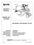
5.5 HORSEPOWER
36" TOW-BEHIND
Modet No. 486.252443
CAUTION:
Before using this product, read
this manuaU and follow aH Safety
RuUes and
Operating
•
•
o
•
•
Instructions.
mMPORTANT-
READ THINSFIRST!!!
For Missing Parts or AssembUy Questions
PUease Call 866-576-8388
Mon.-Fri. 7 am - 5 pm CST.
FAX 217-728-2032
or e-maiU info@agri-fab.com
Missing parts will be sent UPS in 24 hours directly
Sears, Roebuck
and Co., Hoffman
Estates,
Safety
Assembly
Operation
Maintenance
Parts
to your home.
IL 60179 U.S.A.
www, sears,com/craftsman
PRBNTED BNU.S.A.
FORM NO. 49637 (1/05)
TABLE OF CONTENTS
WARRANTY ................................................................
SAFETY RULES ..........................................................
ASSEMBLY ..................................................................
OPERATION ................................................................
MAINTENANCE ..........................................................
2
3
4
6
9
SERVICE AND ADJUSTMENT ................................. 11
STORAGE .................................................................
12
TROUBLESHOOTING ...............................................
13
REPAIR PARTS .........................................................
14
PARTS ORDERING!SERVICE .................... Rear Cover
LiMiTED WARRANTY ON CRAFTSMAN POWERED TRACTOR ATTACHMENTS
For one (1) year from the date of purchase, if this Craftsman Equipment is maintained, lubricated and tuned
up according to the instructions in the owner's manual, Sears will repair or replace free of charge any parts
found to be defective in materia! or workmanship. Warranty service is available free of charge by returning
your Craftsman equipment to your nearest Sears Service Center. In°home warranty service is available but a
trip charge wil! apply. This Warranty applies only while this product is in the United States.
This Warranty does not cover:
Expendable items which become worn during normal use, such as spark plugs, air cleaners, belts, and oil
filters.
Tire replacement or repair caused by punctures from outside objects, such as nails, thorns, stumps, or
glass.
Repairs necessary because of operator abuse, including but not limited to, damage caused by impacting
objects that bend the frame or crankshaft, or over°speeding the engine.
Repairs necessary because of operator negligence, including but not limited to, electrica! and mechanical
damage caused by improper storage, failure to use the proper grade and amount of engine oi!, or failure to
maintain the equipment according to the instructions contained in the owner's manual
Engine (fuel system) cleaning or repairs caused by fuel determined to be contaminated or oxidized (stab).
In general, fuel should be used within 30 days of its purchase date.
Equipment used for commercial or rental purposes.
LIMITED WARRANTY ON BATTERY
For ninety (90) days from date of purchase, if any battery included with the equipment proves defective in
material or workmanship and our testing determines the battery wil! not hold a charge, Sears will replace the
battery at no charge. Warranty service is available free of charge by returning your Craftsman equipment to
your nearest Sears Service Center. In-home warranty service is available but a trip charge wi!! apply. This
Warranty applies only while this product is in the United States.
TO LOCATE THE NEAREST SEARS SERVICE CENTER OR TO SCHEDULE
SIMPLY CONTACT SEARS AT I°800°4°MyoHOME.
SERVICE,
This warranty gives you specific lega! rights, and you may also have other rights, which vary from state to
state.
Record serial number and date of purchase in space
provided below.
PRODUCT
SPECIFICATIONS
_'HORSEPOWER:
5.5 H.R
DISPLACEMENT
12.48 CU. IN.
SERIAL
NUMBER:
GASOLINE TYPE
REGULAR UNLEADED
OIL TYPE
SAE 30 (ABOVE 32 ° F)
DATE OF
PURCHASE:
APPSF/SG)
OIL CAPACITY:
SAE 5W-30 (BELOW 32 ° F
20 OZ.
The model and serial numbers will be found on a
plate attached to the right hand chassis.
SPARK PLUG
(GAP .030")
TILLING GROUND SPEED
TILLING WIDTH
Approx. 2 MPH
36 INCHES
TILLING TINE SPEED
200 RPM
MODEL
NUMBER:
486.252443
You should record both serial number and date of
purchase and keep in a safe place for future
reference.
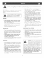
WARNING:Thiscuttingmachineiscapableofamputating
handsandfeetandthrowingobjects.Failureto
observethefollowingsafetyinstructions
couldresultinseriousinjuryordeath.
IMPORTANT
•
Warnings,
Cautions,andNotesarea meansofattracting
attentionto important
or criticalinformation
inthis
manual.
•
Lookforthissymbolto pointoutimportant
safetyprecautions.
It means-Attention!
BecomeAlert!YoursafetyJsinvolved.
•
•
TRAINING
•
•
•
ReadopeningandServiceinstructionscarefully.
Bethoroughlyfamiliarwiththecontrolsandthe
properuseof theequipment.
Neverallowchildrentooperatethe machine.Do
notallowadultstooperatethemachinewithout
properinstruction.
Keeptheareaof operationclearofall persons,
particularlysmallchildrenandpets.
PREPARATION
•
•
•
Checkthefuelandlubricationbeforestartingthe
engine.Donotfill thegasolinetankindoorswhen
theengineis runningor whilethe engineis stillhot.
Wipeoff anyspilledgasolinebeforestartingthe
engine.
Inspecttheareatobetilled.Removeglass,wire,
metalobjects,largesticks,andstones.Avoid
underground
pipesandwiring.
Havea completeworkingknowledge
ofyourtractor
andknowhowto handleyourtractorwitha tilleror
otherattachment
attached.
OPERATION
•
•
•
•
•
Givecompleteandundivided
attentiontothejobat
hand.Operatethetillerindaylightor goodartificial
!_ght.
Personalinjurymayresultfromcontactwiththe
augersordebristhrownbythismachine.
Therefore,
alwaysstaya safedistanceawayfromtheaugers.
Stopthetillerenginewhenleavingyourtiller
unattended.
Checkbeforeeachuseforloosefasteners
or parts.
Neverstoretheequipment
withgasolinein thetank
insideof a buildingwherefumesmayreachanopen
flameorspark.Al!owenginetocoolbeforestoringin
anenclosure.
•
•
•
Stopengineanddisconnect
sparkplugleadwire
beforecleaningaugers,removingobstacles,or
makingadjustments,
exceptforthosewhichmust
bedonewiththeenginerunning.
Neverplacehandsor feetunderor intorotating
partsorconcealedareas.Keephandsandfeet
clearlyawayfromaugerelements,belts,pulleys,
etc.whileengineis running.
Wearsubstantialshoesandeyeprotectionwhile
usingtiller.
Neverattemptto makea maintenance
adjustment
whileengineis running,exceptonthecarburetor.
Donotruntheengineindoors;carbonmonoxide
fumesaredangerousto inhale.
Neveroperatemachinewithoutproperguards,
plates,or othersafetyprotective
devicesin place.
Disengage
theTineClutchLever,stoptillerand
tractorenginesbeforegettingoffthetractor.
Disengage
theTineClutchLeverandstopthetiller
engineduringtransportation
to andfromthework
area.
MAINTENANCE
ANDSTORAGE
•
•
•
Followmaintenance
instructions
as outlinedin this
manualandyourEngineOwner'sManualsupplied
withtheunit.
Disconnect
sparkplugwirebeforemakingmaintenanceadjustmentor repair.
Storegasolinein anapprovedmetalcontainerina
cool,dry place.
Safetyandperformance
levelscanbeassuredonly
bytheuseof specifiedreplacement
parts.
WARNING:
Thisunitis equopedwithan
internalcombustion
engineandshould
notbeusedonor nearanyunimproved
forest-covered
or grass-covered
land
unlesstheengine'sexhaustsystemisequippedwitha
sparkarrestermeetingapplicable
localor statelaws
(ifany).Ifa sparkarresteris used,itshouldbe
maintained
in effectiveworkingorderbytheoperator.
InthestateofCalifornia,
theabovelawis requiredby
law(Section4442oftheCaliforniaPublicResources
Code).Otherstatesmayhavesimilarlaws.Federal
lawsapplyonFederallands.A sparkarresterforthe
muffleris available
throughyournearestSears
Authorized
ServiceCenter.
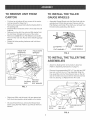
TO REMOVE UNiT FROM
•
•
•
•
•
•
Cut from top to bottom all four corners of the carton
and lay panels flat. (See Fig. 1)
Remove the lag screw that holds the floating hitch to
the packing skid.
Disassemble and discard carton's wood top and side
supports.
Remove four hex bolt, hex nuts and fiat washer from
the hold down brackets at the rear of the carton.
Remove and save the two Flat Washers and Cotter
Pins from the rear axle. Reuse when attaching gauge
wheels.
Discard all other packing hardware and hold down
brackets.
LAG SCREW
WOOD TOP
SUPPORTS
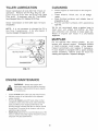
TO iNSTALL THE TILLER
GAUGE WHEELS
Assemble Gauge Wheels onto the Rear Axle with the
extended end of Hub facing inward. Secure with the
Flat Washers and Cotter Pins which you removed from
the axle during unpacking. (See fig. 2.)
HOLD DOWN
BRACKET
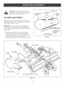
TO INSTALL THE TILLER TINE
ASSEMBLIES
Attach the floating hitch to the tractor's draw bar.
(Refer to Operating instructions on page 7.)
Remove the preassembled 3/8" x 2" hex bolt and 3/8"
hex lock nut from the L.H. Tine Assembly. Slide the
tine assembly onto the Transmission Axle on the left
side of the tiller and secure with the hex bolt and hex
lock nut. (See fig. 3.) Repeat for the R.H. side.
L
WOOD SIDE
SUPPORTS
-':
PACKING
SKID
HEX BOLT
HEX NUT
FLAT WASHER
FiG. 1
3/8" HEX
LOCK
Right hand (RH) and left hand (LH) are determined
from the drivers position while seated on the tractor.
We recommend that you remove the Mower Deck
before using the Tiller. Refer to your Tractor Owner's
Manual.
CUTTING
EDGE
3/8" x 2"
HEX BOLT
FIG. 3
TRAN:
AXLE
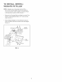
TO iNSTALL (WHEEL)
WEIGHTS TO TILLER
NOTE: Weights are not furnished with the Tiller.
30 Ib. tractor wheel weights may be purchased to
mount to the Tiller if extra weight is required. (Refer
to the Operation section of this manual.)
•
Remove two Carriage Bolts and Nuts from each Tine
Shield, located approximately 3ol/2" from the front
edge. See fig. 4.
•
Place (Wheel) Weights on Tine Shield and secure
with long Bolts and Nuts furnished with the Weights.
See fig. 4.
WHEEL
LONG BOLT:
/
/
TINE
SHIELD
FIG° 4
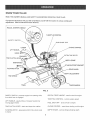
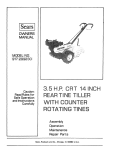
KNOW YOUR TILLER
READ THIS OWNER'S MANUAL AND SAFETY RULES BEFORE OPERATING YOUR TILLER.
Compare the illustrations with your titter to familiarize yourself with the location of various controls and
adjustments, Save the manuaN for future reference.
RECOIL STARTER HANDLE
THROTTLE CONTROL
FUEL SHUT OFF
SAFETY SWITCH
LOWER
CHOKE CONTROL
LIFT HANDLE
RAISE
EXTRA TINE BOLTS
ENGAGED
TINE CLUTCH LEVER
DISENGAGED
STAKE SUPPORT BRACKF
FLOATING HITCH
GUARD
ADJUSTMENT
TINE SHIELD
TINES
GAGE WHEELS
FIG° 5
SAFETY SWITCH - prevents engine from starting while
tine clutch lever is engaged
RECOIL START HANDLE - used to start the engine
THROTTLE CONTROL - controls engine speed
LIFT HANDLE - selects tilling or transport position by
moving gage wheels
FUEL SHUT OFF - shuts of fuel to engine
TINE CLUTCH LEVER - starts and stops tine rotation
CHOKE CONTROL - used when starting a cold engine
FLOATING HITCH - telescoping hitch limits shock loads
to tractor
DEPTH STAKE - controls tilling/cultivating
depth
Theoperationof anytiller canresult in
foreign objects thrown into the eyes, which can
result in severe eye damage. Always wear safety gJasses or eye shields before starting
your tiller and while tilJing. We recommend a wide vision safety mask for over the
spectacles or standard safety gtasses.
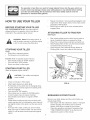
HOW TO USE YOUR TILLER
•
BEFORE
•
STARTING YOUR TILLER
FiLL THE ENGINE WiTH OiL! Your tiller engine is
shipped without oi! or gasoline. Add oil and gas as
instructed in the separate engine manual.
Repeat instructions in two preceding paragraphs until
engine fires. When engine starts, move choke control
gradually to RUN position.
Allow engine to warm up for a few minutes before
engaging tines.
ATTACHING
TILLER TO TRACTOR
(See Fig. 6)
WARNING: Never fill fuel tank indoors, or
with the engine running, or while the engine
is hot. Do not smoke while fitling tank.
•
•
•
STOPPING YOUR TILLER
Rear wheel weights and tire chains can be used on
tractor if additional traction is required for tilling.
Place Tiller on ground leve! and back up tractor to it.
Slide Floating Hitch of TilJer onto the tractor drawbar
so that the hitch pin holes line up.
Insert hitch pin until it extends through bottom of
Floating Hitch. Insert hair cotter pin into hitch pin.
TINES
Raise tiller to transport position.
•
Pul! forward on tine clutch lever.
ENGINE (Refer to separate engine manual.)
•
Move throttle contro! to "STOP" position.
•
Turn shut off to "OFF" position.
•
Never use choke to stop engine.
STARTING YOUR TILLER
HITCH PIN
(Refer to separate engine manual.)
TRACTOR
DRAWBAR
CAUTION: The muffler and adjacent
areas are hot!
HAIR COTTER PIN
•
Check oiI and gas in Tiller engine.
•
•
Attach spark plug wire to spark plug.
Pull forward on tine clutch lever to disengage tines.
A safety switch prevents engine from starting while
tines are engaged.
Turn shut off to "ON" position.
Move choke lever on engine to CHOKE position.
(A warm engine may not require choking.)
Move throttle control lever on engine to FAST
position.
Grasp starter handle and pull rope out slowly until
engine reaches start of compression cycle (rope will
pu!l slightly harder at this point). Let the rope rewind
slowly.
Pull rope with a rapid, continuous, ful! arm stroke.
Keep a firm grip on starter handle. Let rope rewind
slowly. Do not let starter handle snap back against
starten
•
•
•
•
•
FIG. 6
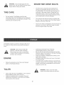
BREAKING
IN YOUR TILLER
Break-in your belts, pulleys and the controI before you
actually begin tilling.
Start engine with tiller attached to tractor in transport
position. Engage Tine Clutch Lever to start tine
rotation. Allow tines to rotate for five minutes.
•
Check tine operation and adjust if necessary. See
"TINE OPERATION CHECK" in the Service and
Adjustments section of this manua!.
TRANSPORTING
YOUR TILLER
®
If the soil is extremely hard and dry, it may be
desirable to cross till an area at shallow depth first,
then tilt in the direction of planting rows on the
second pass at the final depth.
®
Where possible, we recommend tiIHng in a pattern
similar to that shown in Fig. 7. Make the first pass,
then skip a space equal to the width of the tilJer, and
make the return pass. Then till the skipped area.
Ti_ling in this pattern will enable you to maintain
better control. If the passes were made side-by-s_de,
the tractor and tiller would tend to pulJtoward the
tilled (soft) side.
o
Check ground moisture: if you can make a bah in
your hand out of ground to be tilled, do not tilJ soi_ if
too wet. This causes Jumps which are difficult to
work up.
®
When operating for the first time, proceed sJowly and
carafuiey untiJ you become familiar with the proper
method of operating the tiller.
e
In soil that was tilled the year before, select the
tilting depth at which the tiller engine runs
comfortably and does not stall or pull down. Lower
depth for additiona_ passes ff greater depth is desired.
Whenever working multiple passes, go perpendicular to
the previous tilling direction.
In cases where the soiJ is too hard to get proper
penetration or ff tilling action causes Tiller to hop or
bounce, it will be necessary to purchase a set of Tiller
(Wheel) Weights.
AROUND THE YARD
"
Pull forward on tift handle until it locks in the up,
transport position.
AROUND TOWN
,
,
Disconnect spark plug wire,
Drain fuel tank.
Transport in upright position to prevent oil leakage.
TO ADJUST
•
®
®
®
DEPTH
STAKE
Depth stake has five position holes to select tilling
depth from 1 to 5 inches.
The top stake ho_e seJects the shallowest tilling depth
and the bottom stake hole selects the deepest position.
To change depth remove the hair cotter pin from the
clevis pin which is connecting the depth stake to the
stake support bracket.
Grasp the top of the depth stake, remove the clevis pin
and reposition the depth stake. Insert ctevis pin and
hair cotter pin.
tMPORTANT: THE DEPTH STAKE SHOULD NEVER BE
REMOVED FROM THE TILLER. IT IS DESIGNED TO
PROTECT THE TRACTOR TRANSAXLE FROM THRUSTING
ACTION OF THE TILLER
®
,,
TiLLiNG
®
o
The most efficient tillage is obtained when Tiller
Engine is operated at full throttle. The sound of the
Tiller Engine will telt you. When Tiller Engine is
lightly loaded, raise Gauge Wheels to increase titling
depth, if Engine seems to be overieaded or stalls out,
lower Gauge Wheels for shallower tilting.
Operate Tiller Engine at full throttte and operate
tractor in slowest forward speed, with tractor engine
at idle speed or just above idleo You wil_ soon learn
the proper combination of tilling depth and speed for
good tiJlageo
Soil conditions will determine how deep Tiller can
penetrate on the first pass. In extremely hard
ground, several passes may be necessary to til_to a
depth of 6 inches. While in soft ground, Ti_ler may
penetrate to a depth of 6 inches in the first pass.
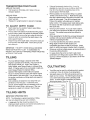
TILUNG
HINTS
o
@
Your tiller may be used for cultivating which requires
a minimum of two (2) inches of soil penetration.
Set depth stake so the Tilter will penetrate soil to a
depth of 2 to 3 inches. The Tiller Engine should be
run at full throttle except when cult_ating small
plants. A slower engine is necessary to prevent
burying the plants. (See fig. 8).
04,01 0
00jOJ 0 0
0 01010
00lOJ 0 0
w
iMPORTANT OPERATING HINTS
NOTE: The following is a general guideline of titting,
but may vary depending upon soil conditions.
®
m _so_L_l
the tiller should be started in the
shallowest depth position and lowered one position at a
time after each pass in each position.
FiG. 7
FiG. 8
GENERAL
RECOMMENDATIONS
Once a year you should replace the spark plug, clean or
replace air filter, and check tines and belts for wear.
A new spark ptug and clean air filter assure proper airfuel mixture and help your engine run better and last
longer.
The warranty on this Tiller does not cover items that
have been subjected to operator abuse or negNgence. To
receive full value from the warranty, operator must
maintain unit as instructed in this manual.
BEFORE EACH USE
Some adjustments will need to be made periodically to
properly maintain your unit.
All adjustments in the Service and Adjustments section of
this manuat should be checked at least once each season.
o
e
,,
Check engine oit level.
Checktine operation.
Check for loose fasteners.
Keep unit well lubricated (See "LUBRICATION CHART").
Refer to the engine manual for instructions on engine maintenance.
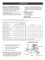
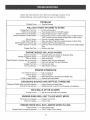
iMAINTENANOESCHEDULE/_/_//
comp,ete
regu,ar
serv,ce.
1_,/_/_#,
Check Engine Oil Level
Change
Engine
_
o _.o
/ _ / _'_/ # _/___#J/_._'/,4"
Fill in dates as you
Oil
Service air cleaner precleaner
_,
_
Service
-,
Dates
---7
X
X
1
X*
X**
Service air cleaner cartridge
X**
X
Replace spark plug
Clean cooling system
i Check valve clearance
Check for loose fasteners
Lubricate Tiller
i Lubricate Tiller Transmission
x
X
*Change oil every 25 hours when operating the engine under heavy load or in high temperatures.
*Clean more often under dusty conditions or when airborne debris is present. Replace air cleaner parts, if very dirty.
LUBRICATION
(_)
CHART
REFER TO SEPARATE ENGINE OPERATING
& MAINTENANCE INSTRUCTIONS
(_)
REFER TO CUSTOMER RESPONSIBILITIES
"TILLER LUBRICATION SECTION."
(_
GENERAL PURPOSE GREASE
IMPORTANT: DO NOT OIL OR GREASE PIVOT POINTS.
VISCOUS LUBRICANTS WILL ATTRACT DUST AND DIRT
THAT CAN CAUSE WEAR ON PIVOT POINTS. IF YOU
FEEL THEY MUST BE LUBRICATED, USE ONLY A DRY
POWDERED GRAPHITE TYPE LUBRICANTS.
ENGINE
(_)
AXLE SHAFT
(_)
®
TILLER _
®
>
TINE SHAFT
FIG. 9
TILLER LUBRiCATiON
Check transmission
oi{ levet after first 5 hours of
operation.
Remove Oil Fill Plug (Fig. 10). Oil
Level must be even with the Plug Hole (with
Tiller level).
If necessary,
add Oil.
Use SAE30
Non-Detergent Motor OiL Replace Oil Fill P_ug.
•
Clean engine
manual
•
Clean
wheels,
matter.
o
Check transmission
of operation.
o
Keep finished
surfaces
and wheels
free of
aHgasoline, oil, etc.
Protect
painted
surfaces
with automotive
type wax.
oii leve_ after each
NOTE:
It is not necessay
to change
this Tiller
Transmission.
If for any
must be changed, Oil capacity is 22 oz,
10 hours
TRANSMISSION
RG. 10
ENGINE MAINTENANCE
WARNING:
Always stop engine and
disconnect spark plug wire before cleaning,
lubricating or before performing any repairs
or maintenance.
•
etc.
of
engine
aH foreign
Do not operate
tiller
without
muffler.
Do not
tamper with exhaust system.
Damaged
mufflers
or spark attesters
could create
a fire hazard.
inspect
periodically
and replace
if necessary.
_f your engine is equipped
with a spark arrester
screen
assembly,
remove
every
50 hours for
cleaning and inspection. Replace if damaged.
C
•
finish,
in the
We do not recommend
using a garden hose to
clean
your unit unless
the muffler,
air filter
and carburetor
are covered
to keep water out.
Water
in engine
can result
in a shortened
engine life,
the OH in
reason
it
OIL FILL PLUG
•
•
as instructed
Check oH level before each use and every 8 hours.
Maintain engine oil as instructed in the separate
engine manual.
Service air cleaner every 25 hours under normal
conditions. Clean every few hours under extremely
dusty conditions. Poor engine performance and
flooding usually indicates that the air cleaner should
be serviced. To service the air cleaner, refer to the
separate engine manual.
Spark plug replacement is recommended every 100
hours or yearly. Check the engine manual for correct
plug type and gap specifications.
10
BELT GUIDE
WARNING: Shut off (disengage) the Tine
Clutch Lever, the Tiller Engine and the Tractor
Engine before making any repairs.
TRANSMiSSiON
PULLEY
CLUTCHING
PULLEY
ENGINE
PULLEY
TO REPLACE V-BELT
Replace V-belt if it has been damaged considerably from
slipping under heavy loads or if it show cracks or frayed
edges. Refer to figures 11 and 12.
IMPORTANT: Do not move or remove the belt guide.
if the position of the belt guide is accidenta!iy altered,
return it to the correct setting (6-1/2" above the tine shield
support plate).
•
•
•
•
•
TINE SHIELD
SUPPORT
PLATE
Remove the screw from the top of the belt guard.
Remove the hex nut from the rear of the guard.
Remove the belt guard to allow access to drive belt.
Disengage tine clutch lever and remove bell
Reverse above procedures for installation of new belt.
BELT RObq'JNG
FIG. 12
BELT GUIDE
DRIVE BELT
SCREW
/
BELT GUARD
T
NUT
TINE SHELD
SUPPORT
FIG. 11
11
PLATE
SPARE TINE DRIVE BOLTS
WARNING: Shut off (disengage) the Tine
Clutch Lever, the Tiller Engine and the Tractor
Engine before making any repairs,
The Tiller drive components are protected from
damage by (shearable) Grade 5 hex bolts in the
Tine Assemblies, The hex bolts drive the tines and
hold them in the proper location, Should the Tine
Assemblies strike or pick up a large hidden object
or become jammed, the hex bolts wil! break and the
drive components wi!! not be damaged,
TINE CARE
For best results--Tine Blades should be kept
reasonably sharp, The Tine Blade can be sharpened
on a grinding wheel, Do not attempt to sharpen Tines
while they are mounted to Tiller,
Two extra tine hex bolts and nuts are included with
the tiller, They are located in the Tiller Stake Support
Bracket on the rear of the Ti!ler,
The tine hex bolts are designed to be loose fit, Do not
attempt to use a bolt or pin that is larger or harder
than the origina! Grade 5 hex bolts,
immediately prepare your tiller for storage at the end of
the season or if the unit wil! not be used for 30 days or
more,
•
CAUTION: Never store the tiller with
gasoline in the tank inside a building,
where fumes may reach an open flame
or spark, Allow the engine to cool before
storing in any enclosure,
•
•
ENGINE
•
•
•
Follow the instructions in the "Service & Storage"
section of the Engine Manua!,
TILLER
Lubricate as instructed in the Customer
Responsibilities section of this manual,
Be sure that all nuts, bolts and screws are securely
fastened, Inspect moving parts for damage, breakage
and wear, Replace if necessary,
Touch up all rusted or chipped paint surfaces; sand
lightly before painting,
If possible, store tiller indoors and cover it to protect
from dust and dirt,
Cover tiller with a suitable protective cover that does
not retain moisture, Do not use plastic, Plastic cannot
breathe, which a!lows condensation to form and will
cause your unit to rust,
WARNING: Never cover Tiller while
engine and exhaust areas are still warm,
Clean entire tiller (See "CLEANING" in the Customer
Responsibilities section of the manual),
Inspect and replace belts, if necessary (See belt
replacement instructions in the Service and Adjustments section of this manual,
12
Follow the instructions in the "Service & Storage" section of the
Engine ManuaU when performing any work on the Engine.
PROBLEM:
ProbabJe Cause ----_
Possible Remedy
WiLL NOT START OR NARD TO START
No gasotine in Fuel Tank
Choke not set proper_y
Throttle Control not set properly
Choked improperly, flooded Engine
Dirty Air Cleaner
Loose Spark Plug Wire
Spark Plug dirty or improper gap
Water in gasoline or old fuel
Clogged Fuel Tank
Fill tank with gasoJine
Place Choke Control in "CHOKE" position
Place Throttle Control in "FAST" position
Move Choke control to "RUN" position, place Throttle Control in
"FAST" position and pull Starter severaJ times to clear out gas
--_
Remove to inspect, replace if dirty
_.
Make sure Spark Plug Wire is seated properly on Spark Plug
Replace Spark Plug and adjust gap
- Drain Fuel Tank and Carburetor, use fresh fuel and replace Spark
Plug
....
Remove and dean
ENGINE M_SSE$ OR LACKS POWER
Engine overloaded
Partially plugged Air Cleaner
Dirty Air Screen
Spark Plug dirty, improper gap or wrong type
Oil in gasoline
C_ogged Fuel Tank
Poor compression
_
_
_
_
_
_
Set Depth Stake and Wheels for shallower tilling
Remove and dean or replace
Clean Air Screen
Replace Spark Plug and adjust gap
Drain and refill gas Tank and Carburetor
Remove and dean
Major Engine overhaul
ENGMNE OVERHEATS
Low oil level or dirty oil _
Dirty Air Screen _
Dirty Engine _
Partially Plugged Muffler
EXCESSIVE
Add or change oil
Clean Air Screen
Clean Cylinder Fins, Air Screen and Muffler area
Remove and clean Muffler
BOUNCE AND DIFFICULT
Wheels and Depth Stake incorrectly adjusted _
Ground too dry and hard _
HANDLING
Adjust Wheels and Depth Stake
Moisten ground or wait for more favorable soil conditions
SOiL ,BALLS UP OR CLUMPS
Ground too wet _
Wait for more favorable soil conditions
ENGINE RUNS WELL BUT TriLLER WON'T MOVE
Tine Control not engaged _
V-Belt off of puJleys _
Engage Tine Control
Check V-Belt
ENGINE RUNS WELL BUT LABORS WHEN T_LLnNG
Ti_ling too deep _
Throttle Control not proper_y adjusted _
Adjust Depth Stake
Check Throttle Control setting
13
_--75
r
_.F
76
2
24
59
13
22
r_
15\
47_,_
75 _
60
68
_Z
30
72
78
/' 79 /
26
/ 27
29
r
r_
rrl
/
32
67
4_
14
83
69
54
16
\
37
-_
28
5O
34
8O
60
23
38
/
28
50
45
67
27
49
80
19
28
O_
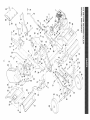
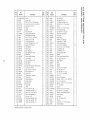
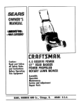
Ref.
No.
Part
Number
} Qty.
Description
}Req.
Ref,
No.
Part
Number
46
47
48
49
50
51
52
53
54
55
56
57
58
59
6O
6t
82
63
64
65
66
67
68
69
7O
71
72
73
74
75
76
77
78
79
80
8t
82
83
84
85
86
87
88
89
90
NP
43054
47600
HA20935
43062
HA20918
R74780828
HA20670
43350
HA20725
HA3433
HA20690
43352
43177
HA20316
47810
41576
43003
43086
24849
HAt4306
HA2069t
43262
HA20938
HA20942
HA57t3
HAt5200
712-0261
44377
48278
43010
HA20688
HA19649
HA120396
HAt24934
HA456151
HA20481
HA7974
R74760884
44326
HA20932
HA20940
HA5236
714-0t17
64284
HA23193
48792
Q_
Description
Req.
i
O-1
1
2
3
4
5
6
7
8
9
10
11
12
13
14
15
16
17
18
19
2O
2!
22
23
24
25
26
27
28
29
3O
31
32
33
34
35
36
37
38
39
4O
41
42
43
44
45
1273020t12E
48346
43085
HAt15321
NAl1154
HA20t76
750-0456
94917
HA19860
84282
43063
43064
64343
48840
43081
HA20135
HA20184
HA20t78
47189
24848
HA23199
24847
HA21362
HA20t70
C@M5732
HA20134
43082
43661
HA20t85
24863
HA20t19
24843
HA20t86
24844
24846
HAl1496
HA20187
43013
HA20936
43182
HA20t12
43178
HA20113
HA20094
HA20088
*Standard
Engine
Guide - Belt
J 1
Bolt, 5/t6-!8 x 1-1/2" Hex Head
Screw, 5/18q 8 x 5/18" Cup Pt. Set
Key, Square 3/16" x 2"
Pulley
Spacer
Stud, Hex Drive
Spring, Depth Extension
Hitch Bracket Assembly
Bolt, 5/!6-18 x !" Hex Head
Locknut, 5/16_18 Rex
Lift Handle Assembly
Screw, Self-Tapping 1/4" x 1/2"
Washer, 5/16" Std. Wrt.
Ring, Retainer
Pulley. Input
Bolt - Shoulder
j4
Nut, Hex Nylock 1/4-20
Clutch Rod
Switch, Safety tntedock
Lever, Clutch
Nut, Hex Nylock 3/8-16
Grip, Handle
Rivet, Pop
Bracket, Belt Guide & Idler Mounting
Locknut, 3/8-!6 Hex
Bolt, 1/4-20 x 1" Hex Head
Key. Woodruff No. 61
Cover, Drive
Transmission _ Complete
Chassis, Left
Spring, Extension
Chassis, Right
Bracket, tdler
Pulley, idler
WBelt
Nut, 1/4-20 Hex Lock
Tine Shield Assembly - LH
Bolt, 5/16q8 x 3/4" Hex Hd.
Rear Guard Assembly - LH
Nut, Hex 1/4-20
Rear Guard Assembly * RH
Tine & Hub Assembly - RH
Tine & Hub Assembly - LH
Hardware _ Purchased Locally
!1
)1
}1
}1
}1
}1
}1
j1
}5
)9
j1
}3
}1
j2
}1
!1
J3
!1
j l
}1
)9
}1
}2
}1
}1o
}11
I1
}1
)1
}1
}1
I1
I1
)1
)1
)9
)1
}4
)1
}1
}1
I1
I
1
Bolt, 3/8-!6 x 2"
Bolt, Hex 5/16_24 x 1"
Tine Shield Assembly - RH
Bolt, 3/8-t6 x 1-1/2" Hex Head
Wheel
Bolt, 1/2-13 x 1-3/4" Hex Head
Pivot Axle Assembly
Bolt, 3/8_16 x 1" Carriage
Strap Frame Extension
Pin, Clevis
Stake, Drag
Washer, 7/16" Std. Wrt.
Lockwasher, 1/4" Med.
Plate, Fender Support
Nut, Hex 5/16-18 Nytock
Bolt _ 3/8-!6 x 1-3/4" Hex Head
Lock Washer, 3/8"
Lock Washer, 5/16"
Belt Guard (incl. #69)
Washer
Strap-Frame Extension Brace
Nut, 1/2-13 Hex Lock
Decal, Danger
Decal
Spacer
Washer
Nut, Hex 5/! 8-11 Nylock
Bolt, Hex 3/8-24 x 1"
Bolt, Hex 5/8ql x 7-1/2"
Pin - 1/8" x 1-1/4" Cotter
Rod - Lift
Anchor _ Adjustment
Washer - 17/32" x 1-1/6" x .095" Flat
Nut - 1/2-20 Hex Jam
Washer _ 13/18" x lq/2" x .134" Flat
Pin - Hair Cotter
Spacer
Bolt, 1/2-13 x 5q/2" Hex Head
Bolt, 5/t6-18 x 1" Carriage
Bracket - Wheel Weight Support
Decal, Danger
Pin, Hitch
Pin - Hair Cotter 5/32"
Module
Screw, 3/8-t6 x 1" Thd. Forming
Owner's Manual
4
1
I
5
2
1
1
8
2
2
1
I
1
1
10
1
1
I
1
1
1
2
2
I
1
2
1
1
1
6
1
1
1
2
4
2
2
1
6
2
1
I
1
1
4
1
_rrl
_Z
r_
r_
rrl
_J
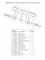
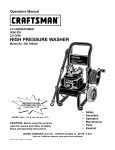
REPAIR PARTS FOR MODEL 486.252443
5.5 HPTOW
BEHIND TILLER
14
24
17
5
11
12
14
23
18
2
21
3
24
10
9
23
13
/
8
12
4
Ref. Part
No.
Number
1
2
3
4
5
6
7
8
9
10
11
12
13
14
15
16
17
18
19
20
21
22
23
24
HA20344
43064
HA20123
HA20122
43013
HA20120
HA20136
HA20127
HA20121
43866
HA20125
HA20124
HA20130
HA20129
HA20132
HA20128
HA20133
HA20131
HA20135
43012
HA20137
HA20145
HA20155
HA20138
*Standard
Descdption
Dust Cap
Locknut, 5/16-18 *
Flange & Bearing Assy
Gasket, Flange
Locknut, 1/4-20 Hex *
Drive Housing & Bearing Assy =LH
Gasket, Drive Housing
Tine Shaft Assy
Drive Housing & Bearing Assy - RH
Bolt, Hex 1/4-20 x 5/8" Grade 8
Washer, Felt
Seal, Rubber
Plug, Transmission Oil
Washer, Thrust
Chain Assembly #40
Chain Assembly #50
input Shaft Assembly
Idler Shaft Assembly
Ring, Retainer 5/8" Dia. Shaft
Bolt - 1/4-20 x 3/4" Hex Head *
Bearing
Seal
Bearing, Flange
Cap, Bearing
Hardware - Purchased Locally
16
Qty.
Req.
2
8
2
2
17
1
1
1
1
15
2
2
1
4
1
1
1
1
1
2
4
1
2
3
3
17
18
19
iiiiiiiiiiiiiiiiiii!_
_¸¸
For repair of major brand appliances
in your own home...
for repair, call for the location of your nearest Sears Parts & Repair Center.
1o800-488ol 222
Anytime,
day or night
www._e_rs.com
For the replacement parts, accessories and owner's manuals
that you need to doqt-yourself, call Sears PartsDirectSM !
1-800o366oPART
(1-800-366-7278}
e a.m.-
11 p.m. CST,
7 days a week
iiiiiiiiiiiiiiiiii
iHHHHHHHHi
HHHHHHHHH
www.sears.com/partsdirect
T° purchase °r'nqu're
Serv'ceAgreement:l
800 ?°ut
827 t 6655
Sears
7am- pmoST
MortSat
Para pedir servicio
y para ordenar
de reparaci6n
a domicilio,
piezas con entrega
1-888-SU-HOGAR
(1-888-784-6427)
Roebuck
and Co
pour service
en frangais:
1-877-LE-FOYER
SM
(1 °877°533°6937)
-
@ Registered Trademark
@ Sears
Au Canada
a domicilio:
/ TMTrademark
of Sears, Roebuck and Co.
® Marca Registrada / TM Marca de Fabrica de Sears
Roebuck and Co
s_