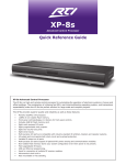
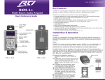
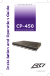
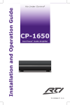
1
Installation and Operation Guide
®
It’s
Under Control®
It’s Under Control
AD-4x
Audio Distribution System
70-210125-18 V1.1
1
AD-4x
Audio Distribution System
Copyright © 2014
Remote Technologies Incorporated
All rights reserved.
2
It’s Under Control®
FEDERAL COMMUNICATIONS COMMISSION NOTICE
This equipment has been tested and found to comply with the limits for a Class
B digital device, pursuant to Part 15 of the FCC Rules. These limits are designed
to provide reasonable protection against harmful interference in a residential
installation. Any changes or modifications not expressly approved by the party
responsible for compliance could void the user’s authority to operate the device.
This equipment generates, uses, and can radiate radio frequency energy and, if
not installed and used in accordance with the instructions, may cause harmful
interference to radio communications. However, there is no guarantee that
interference will not occur in a particular installation.
If this equipment does cause harmful interference to radio or television
reception, which can be determined by turning the equipment off and on, the
user is encouraged to try to correct the interference by one or more of the
following measures:
Reorient or relocate the receiving antenna.
Increase the separation between the equipment and the receiver.
Connect the equipment into an outlet on a circuit different from that to which the receiver is connected.
Consult the dealer or an experienced radio/TV technician for help.
This device complies with Part 15 of the FCC Rules. Operation is subject to the
following two conditions:
1. This device may not cause harmful interference.
2. This device must accept any interference received including interference
that may cause undesired operation.
N27917
DECLARATION OF CONFORMITY (DOC)
The Declaration of Conformity for this product can be found on the RTI website
at: www.rticorp.com/declaration
3
AD-4x
Audio Distribution System
SAFETY SUGGESTIONS
Read Instructions. Read all safety and operating instructions before operating
the unit.
Retain Instructions. Keep the safety and operating instructions for future
reference.
Heed Warnings. Adhere to all warnings on the unit and in the operating
instructions.
Follow Instructions. Install and operate in accordance with the
manufacturer’s instructions.
Accessories. Only use attachments/accessories specified by the manufacturer.
Portable Cart Warning. Use only with the cart, stand, tripod,
bracket, or table specified by the manufacturer, or sold with the
apparatus. When a cart is used, use caution when moving the
cart/apparatus combination to avoid injury from tip-over.
Heat. Do not block any ventilation openings.
Heat. Keep the unit away from heat sources such as radiators, heat registers,
stoves, etc., including amplifiers that produce heat.
Power. Unplug this apparatus during lightning storms or when unused for long
periods of time.
Power Sources. Connect only to the power cord that was included with the
unit.
Power Cord Protection. Route power supply cords so that they are not
likely to be walked on or pinched by items placed on or against them, paying
particular attention to the cords at plugs, at convenient receptacles, and at the
point at which they exit from the unit.
Power Cord Grounding Plug. Do not remove the grounding prong of the
grounding-type plug. A grounding type plug has two blades and a third
grounding prong. The third prong is provided for your safety. If the provided
plug does not fit into your outlet, consult an electrician for replacement of the
obsolete outlet.
MAINS Outlet. Where MAINS outlets are used, the apparatus shall be
connected to a MAINS socket outlet with a protective earthing connection.
MAINS Plug. Where the MAINS plug or an appliance coupler is used as the
disconnect device, the disconnect device shall remain readily operable.
Water and Moisture. Do not use the unit near water—for example, near a
sink, in a wet basement, near a swimming pool, near an open window, etc.
Object and Liquid Entry. Do not allow objects to fall or liquids to be spilled
into the enclosure through openings.
Cleaning. Clean only with dry cloth.
4
It’s Under Control®
SAFETY SUGGESTIONS
Servicing. Do not attempt any service beyond that described in the operating
instructions. Refer all other service needs to qualified service personnel.
Damage Requiring Service. The unit should be serviced by qualified service
personnel when:
Objects have fallen or liquid has been spilled into the unit.
The power supply cord or the plug has been damaged.
The unit does not appear to operate normally or exhibits a marked change
in performance.
The unit has been dropped or the enclosure has been damaged.
WARNING!
TO REDUCE THE RISK OF FIRE OR ELECTRIC SHOCK,
DO NOT EXPOSE THE UNIT TO RAIN OR MOISTURE.
5
AD-4x
Audio Distribution System
LIMITED WARRANTY
Remote Technologies Incorporated warrants its products for a period of one (1)
year from the date of purchase from Remote Technologies Incorporated or an
authorized Remote Technologies Incorporated distributor.
This warranty may be enforced by the original purchaser and subsequent
owners during the warranty period, so long as the original dated sales receipt
or other proof of warranty coverage is presented when warranty service is
required. Except as specified below, this warranty covers all defects in material
and workmanship in this product. The following are not covered by the
warranty:
Damage resulting from:
1. Accident, misuse, abuse, or neglect.
2. Failure to follow instructions contained in this Guide.
3. Repair or attempted repair by anyone other than Remote Technologies
Incorporated.
4. Failure to perform recommended periodic maintenance.
5. Causes other than product defects, including lack of skill, competence or
experience of user.
6. Shipment of this product (claims must be made to the carrier).
7. Being altered or which the serial number has been defaced, modified or
removed.
Remote Technologies Incorporated is not liable for any damages caused by its
products or for its failure of its products to perform, including any lost profits,
lost savings, incidental damages, or consequential damages.
Remote Technologies Incorporated is not liable for damages based upon
inconvenience, loss of use of the product, loss of time, interrupted operation,
commercial loss, any claim made by a third party or made by you for a third
party.
Remote Technologies Incorporated’s liability for any defective product is limited
to repair or replacement of the product, at our option.
If any component of your AD-4x Audio Distribution System needs service,
please contact Remote Technologies Incorporated by telephone, fax or
E-mail for return information. Please do not return products to Remote
Technologies Incorporated without return authorization.
DISCLAIMER
All rights are reserved. No part of this document may be photocopied,
reproduced, or translated without the prior written notice of Remote
Technologies Incorporated.
The information contained in this document is subject to change without
notice. Remote Technologies Incorporated shall not be liable for errors or
omissions contained herein or for consequential damages in connection with the
furnishing, performance, or use of this guide.
AD-4x, Integration Designer, and the RTI logo are registered trademarks of
Remote Technologies Incorporated.
Other brands and their products are trademarks or registered trademarks of
their respective holders.
6
It’s Under Control®
TABLE OF CONTENTS
Federal Communications Commission Notice..................................... 3
Safety Suggestions............................................................................ 4
Limited Warranty.............................................................................. 6
Disclaimer......................................................................................... 6
Table of Contents.............................................................................. 7
Chapter 1 - Welcome......................................................................... 9
- Important Notes...................................................................... 9
- Product Contents.................................................................... 10
Chapter 2 - Features and Description............................................... 11
- Front Panel............................................................................. 12
- Rear Panel.............................................................................. 13
- RSP-1 Remote Source Plate.................................................... 15
- PDM-1 Phone/Doorbell Mute Panel......................................... 16
Chapter 3 - Installation and Operation............................................. 17
- Mounting................................................................................ 17
- Wiring and Connections.......................................................... 17
- Controlling the AD-4x............................................................. 21
- Connection Diagram............................................................... 24
- Using the Web Interface......................................................... 26
Chapter 4 - Specifications................................................................. 34
Chapter 5 - Troubleshooting............................................................. 36
Chapter 6 - Service and Support....................................................... 37
Index............................................................................................... 39
7
AD-4x
8
Audio Distribution System
It’s Under Control®
CHAPTER 1 | WELCOME
Thank you for using the AD-4x Audio Distribution System.
With four audio source inputs and four zone outputs, wherever you go - the
music moves with you. An integrated 8-channel amplifier provides plenty of
power, while zone independent volume and tone control brings the sound to
life. When you combine the AD-4x with RTI central processors, remote controls,
touchpanels, and keypads, this RTI Audio Distribution solution easily keeps pace
with the rhythm of your life.
The AD-4x audio distribution system is designed to be a seamless extension of
an RTI control system. The AD-4x provides the audio switching, amplification
and distribution functions, while RTI central processors and user interfaces
manage the audio source control, user input and status feedback. Information
such as the selected source, volume level, and tone control settings are
available for each zone. Depending on the source equipment used, more
advanced information such as song playlists, cover art, and tuner RDS data
may also be available. Of course with RTI control systems, audio is just the
beginning. Imagine every aspect of your environment working in complete
harmony – from audio and video to lighting, ambience, temperature and
more. Such scenarios are only made possible from an audio distribution
system backed by a professional grade control system. Thanks to the efficient
engineering that defines the AD-4x, there is no reason to limit yourself to a
system that was designed only for music – with RTI so much more is possible.
IMPORTANT NOTES
Please read these important notes about the AD-4x:
The AD-4x should be placed in an area where it is around normal room
temperature (between 60°F to 90°F).
Avoid installing the AD-4x in a location with little or no air circulation.
Avoid installing the AD-4x in a location where it can come in contact with
direct sunlight.
Do not let the AD-4x system get wet. It should not be handled with wet
hands or placed in an area where it could get wet.
Do not subject the AD-4x to smoke, dust, or vibrations.
Only use the power cord that is supplied with the AD-4x. Using the wrong
type of power cord may result in damage.
Do not disassemble the unit. Service of the AD-4x should be performed by
authorized personnel only.
This product is shipped from RTI with AC voltage set to 115 Volts. The
voltage switch will have to be changed for certain international locations.
Dealers should take the following critical step: Set the red voltage
switch on the bottom of the AD-4x to the proper voltage for your
location (115V/230V).
9
AD-4x
Audio Distribution System
CHAPTER 1 | PRODUCT CONTENTS
Contents within the box include the following items:
One (1) AD-4x Audio Distribution System
One (1) AD-4x Faceplate
Four (4) Four Position Phoenix Connectors
One (1) Power Cord
Two (2) Rack Mounting Ears with Screws
One (1) Installation Guide
UNPACKING AND INSPECTION
After unpacking your new AD-4x Audio Distribution System, save all of the
packing materials in case you ever have to ship the unit.
Thoroughly inspect the AD-4x and packing materials for signs of damage.
Report any damage to the carrier immediately. Report any equipment
malfunctions to RTI or an authorized RTI distributor.
IMPORTANT NOTICE FOR DEALERS/DISTRIBUTORS OUTSIDE THE
UNITED STATES
This product is shipped from RTI with AC voltage set to 115 Volts. The voltage
will have to be changed for certain international locations. Ensure that the red
115/230 AC Voltage Switch on the underside of the unit is properly set for your
location.
*The red voltage switch should be left in the 115 Volt position if
used within the United States.
10
It’s Under Control®
CHAPTER 2 | FEATURES AND DESCRIPTION
The AD-4x provides superior quality and reliability as well as these specific
features:
• Four analog stereo audio outputs (either 4 ohm or 8 ohm speakers may be
connected to the zone outputs - One 4 ohm minimum).
• Four analog audio source inputs.
• Cool Power® class-D amplifier provides twenty-five watts per channel.
• Amplifier offers thermal and short-circuit protection.
• Independent volume and tone control for all audio zones.
• Audio input trim adjustment on each source.
• Accessory wall plates (RSP-1) allow source equipment to be connected
remotely with a Cat-5 cable.
• Pre-outputs in each zone allow external amplification for additional power
or speakers in a zone.
• Built-in web interface provides output zone configuration and testing.
• Controlled via IP, RS-232 or Infrared.
• Optional phone and doorbell mute function.
• Zone power indicator LEDs.
• Compact, low-profile design is rack mountable (1U rack form factor) or free
standing.
11
AD-4x
Audio Distribution System
CHAPTER 2 | FEATURES AND DESCRIPTION
AD-4x FRONT PANEL
1
2
3
4
1. Power Switch
Turns AD-4x power on or off.
2. Power LED
A blue LED will be lit up when power is on and will be off when the power is
off.
3. Zone Power LED
A red LED indicates, when lit, that the corresponding zone is on.
4. Recessed Zone Label Holders
A recessed rectangle for placement of a name label (not included) for each
zone.
5. Local Source Inputs
Stereo RCA inputs for audio from up to four independent audio sources. (Ex.
Receiver, cable box, satellite radio etc).
6. Source Input Trim Adjustment
The Trim Control dials are used to equalize signal levels of each input source
to ensure that switching between inputs will result in the same output level.
7. Remote Source Inputs
RJ-45 jacks for connection of up to four RTI remote source wall plates
(model RSP-1) for independent audio sources located remotely (iPod® dock,
CD player, PC etc). RSP-1 wall plates are installed in locations where the
audio source devices will be used (kitchen, office etc) and wired back to the
AD-4x with Cat-5 cable. This provides a convenient audio signal path from
the audio source to the AD-4x, in addition to IR control of the source from
an RTI control system.
8. PREOUT Outputs
Provides line level audio outputs for driving external amplifiers, such as the
RTI CP-450 or CP-1650 amplifiers. The output level is variable and will ramp
up and down with the corresponding AD-4x zone volume control.
12
It’s Under Control®
CHAPTER 2 | FEATURES AND DESCRIPTION
AD-4x REAR PANEL
5
6
7
8
9
11 12
15 17
14 16
10
13
18
19
9. Remote Source IR Control Inputs
These 3.5mm mini-jack inputs are for connecting to an IR output port of
an RTI control system for control of a remote audio source. The IR control
is then delivered over the same Cat-5 cable that runs between the AD-4x
and an RSP-1 RTI Remote Source wall plate (sold separately). There is a
remote source IR control input for each of the four audio sources allowing
for independent IR control of each device. There is also an input labeled “All”
that will allow the delivery of IR to all connected sources at the same time.
10. Mute
This 3.5mm stereo mini-jack is for the connection of an RTI PDM-1 Phone/
Doorbell Mute Module (sold separately). The PDM-1 mutes the AD-4x audio
outputs when a phone/doorbell system sends a voltage to the PDM-1 which
triggers a circuit closure that is sensed by the Mute input.
11. CTRL IN - Infrared Control Input
This 3.5mm mono mini-jack is for infrared control of the AD-4x from
a control system. A discrete set of IR codes is available within the RTI
Integration Designer programming software or on the RTI website (RTI
dealer accessible only).
NOTE: Mini-jack is mono with tip = IR+, ring=Gnd
12. CTRL OUT - IR Pass through
This 3.5mm mono mini-jack allows IR to “pass through” from the CTRL IN
port, for infrared control of additional AD-4x units from a control system.
13. Speaker Outputs
Four sets of removable stereo connectors for speakers in each zone. Either 4
ohm or 8 ohm speakers may be connected to the zone outputs.
NOTE: Connected speakers must have a 4 ohm minimum load or damage to
the unit may occur.
14. ID Number
Installations can have up to 8 AD-4x units installed
providing up to 32 output zones. To allow discrete IR
control each unit is given a unique ID. Discrete IR code
libraries are available for each unique ID. To set the ID
for each AD-4x unit, refer to the ID assignment chart
and adjust as necessary.
A2
0
0
0
0
1
1
1
1
A1
0
0
1
1
0
0
1
1
A0
0
1
0
1
0
1
0
1
ID No.
1
2
3
4
5
6
7
8
13
AD-4x
Audio Distribution System
CHAPTER 2 | FEATURES AND DESCRIPTION
AD-4x REAR PANEL - CONTINUED
15. +12VDC
This 3.5mm mono connection provides a constant +12VDC output (500mA
max).
16. Status
This 3.5mm mono connection provides a +12VDC output when any zone
is turned on (15mA max). This can be used to trigger external equipment.
When all zones are turned off, 0VDC is present.
17. RS-232
DB-9 jack for RS-232 control of the AD-4x from a control system. See
Chapter 3 Installation & Operation for RS-232 control details.
DB-9 Pinout
2
3
5
TXD RXD
GND
Transmit Data
Receive Data
Ground
18. Ethernet Port
The Ethernet port (RJ45) allows for bi-directional control from an RTI XP
series control processor over an Ethernet network (LAN). A two-way driver
is available on the RTI website (dealer section) that will enable this type of
control.
19. AC Power Socket and Fuse
Three-pin grounded socket to connect removable AC power cord with a T2AL
250V fuse.
IMPORTANT POWER NOTICE
This product is shipped from RTI with AC voltage set to 115 Volts. The
voltage switch will have to be changed for certain international locations.
Dealers should take the following critical step.
•S
et the red voltage switch on the bottom of the AD-4x to the
proper voltage for your location (115V/230V)
14
•T
he red voltage switch should be left in the 115 Volt position if
used within the United States.
It’s Under Control®
CHAPTER 2 | FEATURES AND DESCRIPTION
RSP-1 REMOTE SOURCE PLATE* - FRONT
1
3
Remote Source
L
2
R
L/R
4
IR
5
L/R & IR
1. Audio Inputs - RCA
Two RCA input jacks for connection to the output (left and right) of the
remote audio source (Internet music streamer, CD Player etc).
2. Audio Inputs - 3.5mm
One 3.5mm stereo mini jack for connection to the output of the remote
audio source (iPod®, PC etc).
3. IR Output
One 3.5mm mono mini jack for connection of an IR emitter to control the
remote source. IR control delivered from control system.
4. Audio Inputs and IR Output
This RJ-45 connection carries the left and right audio inputs from the remote
source and the IR control output over Cat-5 cable.
Note: This would not normally be used.
5. Decora® faceplate (not included)
Compatible with standard single-gang Decora® style faceplates.
RSP-1 REMOTE SOURCE PANEL - REAR
6. Mounting holes
Use screws to mount the RSP-1 in a standard
single-gang electrical box.
6
Remote Source
Source Plate
Remote
Plate
Model
Made in Taiwan
117 612 914
RSP/01
S/N
Model
RSP-1
S/N
7
RSP-1
Remote Technologies Inc.
www.rticorp.com
7. Audio and IR control - RJ-45
This RJ-45 connection carries the left and right
audio inputs from the remote source and the IR
control output between the AD-4x and the remote
source.
P/N 20-210125-13
*Note: RSP-1 sold separately.
15
AD-4x
Audio Distribution System
CHAPTER 2 | FEATURES AND DESCRIPTION
PDM-1 PHONE/DOORBELL MUTE PLATE* - FRONT
The back panel of the AD-4x has a 3.5mm stereo connector input labeled
“Mute”. This is designed to be used with the PDM-1 Phone/Doorbell Mute
module. When the PDM-1 is installed, the system will temporarily mute
when the phone or doorbell rings.
1
PDM1
Phone Doorbell Module
To
Mute
2
1. Phone - Doorbell Output - 3.5mm
This 3.5mm stereo mini jack is for connecting to the “Mute” connection on
the rear panel of the AD-4x. (See the AD-4x rear panel description)
2. Decora® faceplate (not included)
Compatible with standard single-gang Decora® style faceplates.
PDM-1 PHONE-DOORBELL MUTE MODULE - REAR
PDM-1
Model
P/N 20-210126-14
Phone Doorbell Module
4
S/N
117 612 914
TO TEL
5
TO DOORBELLS
#1
#2
3
Remote Technologies Inc.
www.rticorp.com
Made in Taiwan
PDM1/01
3. Mounting holes
Use screws to mount the PDM-1 in a standard single-gang electrical box.
4. Doorbell Connectors
The PDM-1 phoenix connector will accept up to two AC or DC voltages from
two different doorbell chimes. This connection is done with two conductor
wire from the terminals on the doorbell chime to the Doorbell 1 or Doorbell
2 inputs on the back of the PDM-1. Polarity is not important for this
connection.
5. Phone System - RJ-11
A single phone line can be brought into the RJ-11 connection on the back
of the PDM-1. The ring voltage from the phone line will trigger the AD-4x
system to mute.
*Note: PDM-1 sold separately.
16
It’s Under Control®
CHAPTER 3 | INSTALLATION AND OPERATION
FREE STANDING
The AD-4x ships with four removable feet that allow it to be placed on a flat
surface. To maintain proper ventilation and cooling, do not install the AD-4x on
a flat surface without the feet.
RACK MOUNT
The AD-4x can be mounted in a component rack as part of a comprehensive
audio/video electronics system using the included rack mounting ears. Align
the rack mounting ears with the screw holes located on the sides of the AD-4x
near the front. Fasten the rack ears to the AD-4x using three screws (supplied).
Remove feet before mounting in a rack.
NOTE: To maintain proper ventilation, it is recommended that you leave a rack
space above and beneath the AD-4x if possible.
Rack Mounting Ears
Model AD-4
Audio Distribution System
POWER
ZONE 1
ZONE 2
ZONE 3
ZONE 4
Foot
CONNECTING THE 115VAC POWER CORD
The included AC power cord must be inserted into the AC input receptacle on
the AD-4x. When the AC power cord is connected to a power source, press the
Power button to turn the AD-4x on and off.
IMPORTANT NOTICE FOR INTERNATIONAL DEALERS/DISTRIBUTORS
This product is shipped from RTI with AC voltage set to 115 Volts. The voltage
will have to be changed for certain international locations. Ensure that the red
115/230 AC Voltage Switch on the underside of the unit is properly set for your
location.
*The red voltage switch should be left in the 115 Volt position if
used within the United States.
CONNECTING LOCAL AUDIO SOURCES
The AD-4x has four sets of RCA audio inputs for connecting up to four external
source components. These four audio sources can be selected to play in up to
four zones. Also, if users in more than one zone choose the same audio source,
control of that source is shared between the zones.
•T
rim Control: The Trim Control dials on the AD-4x are used to equalize
signal levels of each input source to ensure that switching between inputs will
result in the same output level. The Trim Control is initially set at zero (no
attenuation).
AD-4x Local Inputs
Audio Source (ex. Satellite radio)
Source 1
Tuner
Audio
Out
17
AD-4x
Audio Distribution System
CHAPTER 3 | INSTALLATION AND OPERATION
CONNECTING REMOTE AUDIO SOURCES
(See “Connecting Remote Audio Sources” diagram)
Audio sources that are located in other areas can have their audio signals
delivered back to the AD-4x and shared among all of the output zones.
NOTE: Local audio inputs (1-4) and remote audio inputs (1-4) are common,
limiting the AD-4x to four audio sources total. Any combination of local and
remote sources may be used, to a maximum of four. For example, do not plug
in a local audio source to local input 1 and remote audio source to the remote
input 1.
WIRING FOR REMOTE AUDIO SOURCES
Use standard Cat-5 cable between the RSP-1 Remote Source Plate and the
RJ-45 jacks on the rear of the AD-4x. Use either the stereo RCA jacks or the
3.5mm mini stereo jack for connecting to the output of the audio source.
NOTE: It is not possible to “Y” or split the audio signals from the RSP-1 to
multiple AD-4x units.
NOTE: The AD-4x can accommodate 500 total feet of Cat-5 cable for each
zone. For the most reliable operation, it is best that no single run of Cat-5
exceeds 250 feet. The correct wiring scheme for the Cat-5 cable is standard
EIA/TIA 568B. Properly terminating the Cat-5 cable is crucial for the operation
of the system.
CONTROLLING REMOTE AUDIO SOURCES
Remote audio sources can be controlled from their own front panel or via
infrared control delivered over the same Cat-5 cable wired to the RSP-1 Remote
Source Panel that is used for the audio signal (see above). The IR commands
used to control the sources come from an RTI control system which is wired
to the IR inputs located on the rear of the AD-4x. Each remote source has an
individual IR input for independent control and commands sent to the “All” input
on the AD-4x will allow control of all remote sources if routing the IR codes is
not necessary.
18
It’s Under Control®
CHAPTER 3 | INSTALLATION AND OPERATION
CONNECTING REMOTE AUDIO SOURCES
RTI XP6 Processor
USB
ETHERNET
RTI COM
EXPANSION
Model XP-6
Advanced Control Processor
RESET
+
STATUS
POWER / IR
POWER
+12VDC TRIGGER
+3-24VDC SENSE
+
IR OUTPUT LEVEL
+
+
+
+
RELAYS (+30VDC, 5A MAX)
RS-232
1
2
PORT 1
PORT 2
PORT 3
PORT 4
PORT 5
PORT 6
RSP-1 Rear
AD-4x
Remote Source
Source Plate
Remote
Plate
RSP-1
Remote Technologies Inc.
www.rticorp.com
Model
Made in Taiwan
117 612 914
RSP/01
Model
RSP-1
S/N
S/N
Cat-5
P/N 20-210125-13
RSP-1 Front
Remote Source
L
R
L/R
IR
L/R & IR
Audio
Signal
IR
Emitter
Receiver
19
AD-4x
Audio Distribution System
CHAPTER 3 | INSTALLATION AND OPERATION
WIRING FOR MUTE INPUT
The back panel of the AD-4x has a 3.5mm non-shorting stereo connector input
labeled “Mute”. This is designed to be used with the PDM-1 Phone-DoorbellMute module. When the PDM-1 is connected, the system will temporarily mute
when the phone or doorbell rings.
Doorbell
The back of PDM-1 will accept up to two AC or DC voltages from two different
doorbell chimes. This connection is done with two conductor wire from the
terminals on the doorbell chime to the Doorbell A or Doorbell B inputs on the
back of the PDM-1, Polarity is not important for this connection.
Telephone Paging
The ring voltage from a phone line will trigger the AD-4x system to mute.
AD-4x
Made in Taiwan
PDM1/01
Phone
Service
(POTS)
Doorbell
Switch
20
Model
PDM-1
PDM1
Phone Doorbell Module
To
Mute
S/N
117 612 914
TO DOORBELLS
#1
#2
Phone Doorbell Module
TO TEL
Remote Technologies Inc.
www.rticorp.com
P/N 20-210126-14
PDM-1
Rear - Front
Doorbell
It’s Under Control®
CHAPTER 3 | INSTALLATION AND OPERATION
SPEAKER WIRE TERMINATION
Install the four supplied phoenix connectors into the audio zone outputs on the
AD-4x. Connect the positive and negative wires for each audio channel output,
keeping the proper orientation of positive and negative signal for each speaker
connection. Typically, two-conductor speaker wire uses red to denote positive
and black to denote negative. Some types of wire indicate positive with a line
running through the insulation. Four-conductor wire can also be used. This
has four separated wires in one outer jacket, making it possible to run a single
speaker wire to a zone for its pair of speakers. This type of wire typically uses
red and black for one speaker and white as positive and green as negative for
the second speaker.
CAUTION: Do not short speaker wires together if they are connected to
the AD-4x, as damage to the unit may result.
IR CONTROL OF AD-4x
A 3.5mm mono mini jack labelled CTRL IN, located on the rear of the AD-4x
allows for hard-wired IR control from a control system. A library of infrared
codes is available within the RTI Integration Designer programming software or
on the RTI website (accessible to RTI dealers only). Installations can have up to
8 AD-4x units installed. To allow discrete IR control each unit is given a unique
ID (see page 13). Discrete IR code libraries are available for each unique ID.
RS-232 CONTROL OF AD-4x
A DB-9 jack offers RS-232 control of the AD-4x from an RTI or third-party
control system. A set of RS-232 codes is built into the Integration Designer
programming software and a two-way driver is available on the RTI website
(dealer section).
NOTE: DO NOT use both RS-232 and IP for control simultaneously. Using both
control methods at the same time will affect control reliability.
Connection Settings:
Baud rate: 9600
Data bits: 8
Parity: None
Stop bits: 1
DB-9 Jack Pinout:
2
TXD Transmit Data
3
RXD
Receive Data
5 GND Ground
21
AD-4x
Audio Distribution System
CHAPTER 3 | INSTALLATION AND OPERATION
IP CONTROL OF AD-4x UNITS - ETHERNET
The built-in Ethernet port allows convenient control of one or more AD-4x units
(maximum 8) using IP via an Ethernet network (LAN) from an RTI XP processor.
Configuration of the AD-4x networking is done through a web interface which
is accessible through any web browser (See “CONFIGURING THE AD-4X USING
THE WEB INTERFACE” section of this guide).
NOTES: For IP control:
•D
O NOT use both RS-232 and IP for control simultaneously. Using both
control methods at the same time will affect control reliability.
•T
he RTI control system must have a two-way driver running on the XP
processor.
•T
he RTI control system and each AD-4x must be connected to the same
Ethernet network (LAN).
AD-4x #1
AD-4x #2
Cat-5
Cat-5
Cat-5
USB
ETHERNET
RTI COM
EXPANSION
Model XP-6
Advanced Control Processor
RESET
+
STATUS
POWER / IR
POWER
Network Router/Switch
22
+12VDC TRIGGER
+3-24VDC SENSE
+
IR OUTPUT LEVEL
+
+
+
+
RELAYS (+30VDC, 5A MAX)
1
RS-232 2
PORT 1
PORT 2
PORT 3
PORT 4
PORT 5
PORT 6
RTI XP
Control
Processor
It’s Under Control®
CHAPTER 3 | INSTALLATION AND OPERATION
EXPANDING TO EIGHT OUTPUT ZONES
It is possible to expand the number of output zones using two AD-4x Audio
Distribution Systems together. This allows four local audio sources to be
delivered to eight zones.
Local Source Cabling
A “Y” cable will need to be used to split the audio output of the local audio
source and wired to the local audio source inputs on both AD-4x units.
NOTE: It is not possible to “Y” or split the audio signals from the RSP-1 to
multiple AD-4x units, limiting their output to a maximum of four zones.
AD-4x #1
Local Audio Source
(ex. Tuner or CD)
Source 1
Tuner
Audio
Out
AD-4x #2
Controlling Multiple AD-4x’s using RS-232
Each AD-4x will require an RS-232 connection to an RTI control processor. This
will allow each AD-4x to be controlled separately, allowing for independent
control in all eight output zones.
USB
ETHERNET
RTI COM
EXPANSION
Model XP-6
Advanced Control Processor
RESET
+
STATUS
POWER / IR
POWER
+12VDC TRIGGER
+3-24VDC SENSE
+
IR OUTPUT LEVEL
+
+
+
+
RTI XP6 Processor
RELAYS (+30VDC, 5A MAX)
RS-232
1
2
PORT 1
PORT 2
PORT 3
PORT 4
PORT 5
PORT 6
Cat-5
AD-4x #1
AD-4x #2
23
AD-4x
Audio Distribution System
CHAPTER 3 | INSTALLATION AND OPERATION
AD-4x CONNECTION DIAGRAM
Audio Output
Audio Output
Cat-5
Cat-5
24
It’s Under Control®
RTI CB8
ZM-24
Transceiver
Module
RTI Remote Control
RTI Keypads
USB
RTI COM
ETHERNET
XP-6
EXPANSION
Model XP-6
Advanced Control Processor
RESET
+
STATUS
POWER / IR
+12VDC TRIGGER
+3-24VDC SENSE
+
IR OUTPUT LEVEL
+
+
+
+
RELAYS (+30VDC, 5A MAX)
RS-232
POWER
1
2
PORT 1
PORT 2
PORT 3
PORT 4
PORT 5
PORT 6
RS-232
RJ45>DB9
Adapter
AD-4x
Audio
Zone 1
Pre-Out
Audio
Cables
Audio
Zone 3
Audio
Zone 2
Audio
Zone 4
LAN Router/Switch
(See IP Control
section)
RTI CP-450
Amplifier
Audio
Zone 4
Audio
Zone 5
25
AD-4x
Audio Distribution System
CONFIGURING THE AD-4X USING THE WEB INTERFACE
The AD-4x web interface is accessible via a standard web browser (Internet
Explorer®, Firefox® , Safari® etc) on a PC, tablet or smartphone.
The web interface is used for:
• Configuring networking - IP address etc.
•T
esting output zones - Each zone can have it’s current source, volume, power
and mute status adjusted during the setup process.
•Z
one grouping - Output zones may be assigned to a “group”, allowing multiple
zones to be controlled simultaneously as a single output zone.
ADDING THE AD-4X TO THE ETHERNET NETWORK (LAN)
Wire the AD-4x to the Ethernet network using Cat-5 cable with the RJ45
termination and power the unit on. The network router will assign an IP address
to the Ad-4x automatically and allow it to join the network.
• The AD-4x is set to use DHCP by default.
• Router must have DHCP enabled.
ACCESSING THE WEB INTERFACE
To access the web interface, first determine the IP address that was assigned
to the AD-4x by the network router which can be found by looking for UPNP
devices on the network.
NOTE: If using Windows XP, you may need to enable viewing of UPNP devices
and “Windows Discovery”.
• Click on My Network Places
• If UPNP devices are not displayed, under Network Tasks, click on “Show
icons for networked UPNP devices”. Click yes to allow the installation
wizard.
To view UPNP devices on the network, go to the “network” area in your version
of Windows.
•
•
•
•
In the “Computer” tab under the Start Menu.
Click on “Network”.
On the right side window, scroll down to “Other Devices”.
Find the AD-4x in the list of devices and double click on the icon to open the
web interface.
OR
•T
he AD-4x icon will display the IP address it is using. Open a web browser
on your PC, tablet or smartphone and type the IP address into the browser
address bar.
26
Example: http://192.168.0.15
It’s Under Control®
WEB INTERFACE - STATUS PAGE
After entering the IP address into the web browser and hitting enter, the Status
Page will be the first page displayed. The information includes the AD-4x name,
firmware version, IP address and MAC address.
WEB INTERFACE - LOGIN
To configure the AD-4x settings, click on the “Configuration” button to login.
NOTE: The default password is: rti
27
AD-4x
Audio Distribution System
WEB INTERFACE - NETWORK CONFIGURATION PAGE
Upon logging into the web interface the Network Configuration page will be
displayed. You can also reach this page by clicking “Network” tab at the bottom
of the web interface.
IP ADDRESS CONFIGURATION
IMPORTANT NOTES:
•S
etting a static IP address is NOT necessary and is discouraged. The RTI
two-way driver uses the UPNP name of the AD-4x to find it on the network
so a static IP is unnecessary.
•S
etting a static IP address and clicking “Update Settings” will cause the
web interface to no longer be displayed in your web browser. Enter the
new static IP address into your web browser address bar to access the web
interface again.
To set the static IP address:
1. Select Address Type (set to DHCP by default): click this button and select
“Static IP” from the drop down list.
2. Enter Static IP Address: Enter the static IP address.
3. Enter Subnet Mask: Enter the network subnet used by the AD-4x and RTI
XP processor.
4. Enter Default Gateway: Enter the IP address of the network gateway.
5. Click on the “Update Settings” button to save these settings.
NOTE: To manually reset the AD-4x to DHCP
If the wrong IP address scheme is used during the static IP setup process, the
AD-4x will not be accessible via the network. If this happens, the AD-4x web
interface will not be available to make corrections and control via IP will not be
possible.
To correct this, the AD-4x will need to be manually set back to DHCP using an
RS-232 string so that it may rejoin the network, and allow the web interface to
be used again.
Steps to reset IP Address Type to DHCP:
1. C
onnect a serial cable between your RTI control processor (or PC) and the
AD-4x. (See “RS-232 CONTROL OF AD-4x” for cable requirements).
2. Send this RS-232 string followed by a carriage return: ^rti dhcp
• There is a space between the “i” and the “d”.
• The string with carriage return using Integration Designer is: ^rti dhcp\r
3. F
ollow the steps in the “ACCESSING THE WEB INTERFACE” section to gain
access to the web interface again.
NETWORK IDENTIFICATION
This section allows you to change the name of the device as it shows up on the
network and list of UPNP devices.
1. Unit Name: Enter a new AD-4x name
2. Click on the “Update Settings” button to save these settings.
28
It’s Under Control®
WEB INTERFACE - NETWORK PAGE
29
AD-4x
Audio Distribution System
WEB INTERFACE - ZONES PAGE
The Zones page of the web interface is used during AD-4x setup, allowing you
to adjust the source, power, mute, volume and the assigned group from a
device with a web browser such as a PC, tablet or smartphone.
View this page by clicking “Zones” tab at the bottom of the web interface.
ZONE CONFIGURATION
Click the “+” next to the zone you wish to configure and test.
• Sources: Select the audio input source for this zone.
• Power: Click on this button to power the zone on and off.
• Mute: Click on this button to mute the zone on and off.
• V
olume: Current volume level is displayed on volume slider bar. To adjust
the volume level, use the raise and lower buttons or click on the volume
slider bar to jump to a level.
CAUTION: C
licking on the volume level bar will cause the volume to
JUMP to that level - be VERY careful where you click to
prevent accidently raising the volume to a high level.
• Group: Select the group that this zone will be a member of, or select “None”.
Grouped zones will be controlled together, allowing volume levels to be
adjusted simultaneously in multiple zones.
NOTE: Zones can only be a member of one group.
30
It’s Under Control®
WEB INTERFACE - ZONES PAGE
In this example Zone 3 is configured:
• Source: 4 is selected
• Power: is ON
• Mute: is OFF
• V
olume: set to -30dB
• Group: is a member of Group 2
31
AD-4x
Audio Distribution System
WEB INTERFACE - GROUPS PAGE
The Groups page of the web interface is used during AD-4x setup, allowing
you to adjust power, mute and volume of each group from a device with a web
browser such as a PC, tablet or smartphone.
View this page by clicking “Groups” tab at the bottom of the web interface.
GROUPS CONFIGURATION
Grouped zones will be controlled together, allowing volume levels to be adjusted
simultaneously in multiple zones, such as in an adjoining kitchen/family room.
The group names are followed by the zones that are members of each group.
Click the “+” next to the group you wish to configure.
• Power: Click on this button to power the grouped zones on and off.
• Mute: Click on this button to mute the grouped zones on and off.
• V
olume: To adjust the volume level of a group, use the raise and lower
buttons.
NOTES:
32
•V
olume will raise until the maximum limit is reached in any zone in the
group. At that point the other zones in the group will stop raising the
volume level.
•V
olume will lower until the minimum limit is reached in any zone in the
group. At that point the other zones in the group will stop lowering the
volume level.
It’s Under Control®
WEB INTERFACE - GROUPS PAGE
33
AD-4x
Audio Distribution System
CHAPTER 4 | SPECIFICATIONS
GENERAL
Power Supply
Mounting
Dimensions
(W x H x D)
Weight
Warranty
115 AC, 120W
Rack mount or free standing
16.9” (430mm) x 2.1” (53mm) x 13.3” (339mm)
11.0 lb. (5kg)
One Year (Parts & Labor)
CONTROL & CONNECTIONS
Total Output Zones
Four zones, two channels each (either 4 ohm or
8 ohm speakers may be connected to the zone
outputs)
Pre-Outs
Audio Sources
Four, RCA jack pairs
Maximum four, local and remote combined.
Audio Source Inputs
(Local)
Four, RCA jacks
Audio Source Inputs
(Remote)
Four, RJ-45 jacks
Control Input
Remote Source IR
Inputs
Mute Input
One, 3.5mm jack, compatible with industry standard
IR repeaters and receivers
Five, 3.5mm jacks, compatible with industry
standard IR emitters
One, 3.5mm jack
Phone Input Sensitivity: AC25V-AC100V 20Hz
Doorbell Sensitivity: AC/DC 3-12VDC
Trigger Output (Status One, 12VDC, 15mA max
Jack)
Voltage Output
RS-232 Ports
One, Bi-directional DB-9
Ethernet Port
One, 10/100Base-T, RJ45 Connection
Unit ID Numbers
34
One, 12VDC, 500mA max
1-8, Set using 3 switches
It’s Under Control®
CHAPTER 4 | SPECIFICATIONS
AUDIO
Total Output Zones
Four zones, two channels each
Rated Power /
Channel
>20 Watts, 20Hz to 20KHz
(RMS, 2 channels driven into 8 ohms)
Power / Channel
>25 Watts @ 1KHz
(RMS, 2 channels driven into 8 ohms)
Total Harmonic
Distortion
@20W/8ohm
Total Harmonic
Distortion @1W/8ohm
0.05%
<0.05%
S/N @ Rated power,
IEC A-wtd, Source
input shorted
92dB (mute +1)
Frequency Response
20Hz to 20KHz @
1W/8ohms
1.5+/-0.5dB
Input Overload
Input Impedance
2.5V
>22K ohms
Channel Separation
@1KHz
>60dB
Crosstalk Between
Sources @ Rated
Power /1KHz
>75dB
Crosstalk Between
Zones @ Rated Power
/1KHz
80dB
Treble Control
@10KHz
10dB +/- 0.5dB
Bass Control Range
@100Hz
10dB +/- 0.5dB
All specifications subject to change without notice.
35
AD-4x
Audio Distribution System
CHAPTER 5 | TROUBLESHOOTING
If you are having problems with your AD-4x Audio Distribution System, please
read the information below before contacting technical support.
If you continue to have problems, see Chapter 6 for more information on
contacting RTI technical support.
AD-4x DOES NOT FUNCTION PROPERLY
Symptom: No sound
Possible Causes:
- AC power unplugged > Check AC cable and outlet.
- Main power switch not on > Is main power light on?
- Outlet has no power > Verify outlet has power.
- Blown fuse > Check main fuse.
- Mute jack > Is mute jack in active mode?
Symptom: No sound from individual zones.
Possible Causes:
- Faulty wiring > Verify all wiring.
- Zone output not on > Are zone output light(s) on?
Symptom: No sound via remote source wallplate.
Possible Causes:
- Faulty wiring > Verify all wiring & terminations.
- Verify source output > Make sure source has audio output.
Symptom: No IR control via remote source wallplate.
Possible Causes:
- Faulty wiring > Verify all wiring & terminations.
- IR signal level > Adjust IR signal going into AD-4x.
- IR emitter > Verify IR emitter is working.
- IR emitter placement > Verify emitter is properly placed.
Symptom: No IR control of AD-4x.
Possible Causes:
- Faulty wiring > Jack is 1/8” mono, tip = IR+, ring=Gnd.
- IR signal level > Adjust IR signal going into AD-4x.
- CTRL IN > Verify connection is to CTRL IN
Symptom: No RS-232 control of AD-4x.
Possible Causes:
- Faulty wiring > Check RS-232 pinout.
- Incorrect string > Verify RS-232 string is correct.
- No carriage return > String requires carriage return.
Symptom: Distortion when using RSP-1
Possible Causes:
- I R output on the RTI control processor > Reduce IR output from RTI control
processor.
36
It’s Under Control®
CHAPTER 6 | SERVICE AND SUPPORT
For news about the latest updates, new product information, and new
accessories, please visit our web site at:
www.rticorp.com
CONTACTING RTI
For general info, you can contact RTI at:
Tel. (952) 253-3100
Fax (952) 253-3131
info@rticorp.com
RTI TECHNICAL SUPPORT
At RTI, customer service and satisfaction is an utmost priority. If you are
encountering any problems or have a question about your RTI product, please
contact RTI Technical Support for assistance.
RTI provides technical support by telephone, fax or e-mail. For the highest
quality service, please have the following information ready, or provide it in
your fax or e-mail.
Your Name
Company Name
Telephone Number
E-mail Address
Product model and serial number (if applicable)
If you are having a problem with hardware, please note the equipment in your
system, a description of the problem, and any troubleshooting you have already
tried.
If you are having a problem with software, please note what version you have
installed, the operating system on your PC, a description of the problem, and
any troubleshooting you have already tried.
If you are calling about a software or programming question or problem, please
be at you computer when you place your call. This will considerably speed up
the troubleshooting process.
For technical support or assistance with your AD-4x, software, or accessories,
contact RTI at:
(952) 253-3137
support@rticorp.com
www.rticorp.com
For questions regarding service or repair of your AD-4x, contact RTI at:
(952) 253-3136
service@rticorp.com
www.rticorp.com
Please do not return products to RTI without return authorization.
37
AD-4x
Audio Distribution System
CHAPTER 6 | SERVICE AND SUPPORT
Shipment of AD-4x for Service
RTI will pay all labor and material expenses for all repairs covered by this
product’s warranty. If necessary repairs are not covered by warranty, or if
a unit is examined which is not in need of repair, you may be charged for
the repairs or examination.
If it is necessary to ship the AD-4x for service: Please pack it securely (we suggest that it be insured).
Do not include accessories such as power cords or manuals unless instructed to do so.
You must pay any shipping charges incurred in getting your AD-4x to RTI.
RTI will pay reasonable return shipping charges via a carrier of our choice
to any destination within the United States if the repairs are covered under
warranty.
A copy of the original dated sales receipt must be provided whenever
warranty service is required. You will need this receipt to establish the date
of purchase.
38
It’s Under Control®
INDEX
Table of Contents................................................................. 7
Description....................................................................... 12
AD-4x Front Panel.......................................................... 12
AD-4x Rear Panel........................................................... 13
RSP-1........................................................................... 15
PDM-1.......................................................................... 16
Disclaimer.......................................................................... 6
Features........................................................................... 11
Federal Communications Commission Notice........................... 3
Installation/Operation........................................................ 17
Connection Options........................................................ 17
Connections Diagram...................................................... 24
Control (IR/RS-232/IP)................................................... 21
Mounting/Power............................................................. 17
Important Notes.................................................................. 9
Limited Warranty................................................................. 6
Product Contents............................................................... 10
Safety Suggestions.............................................................. 4
Service and Support.......................................................... 37
Specifications.................................................................... 34
Troubleshooting................................................................. 36
Welcome............................................................................ 9
39
AD-4x
Audio Distribution System
It’s Under Control®
Remote Technologies Incorporated
5775 12th Avenue East, Suite 180
Shakopee, MN 55379
Tel: 952-253-3100
Fax: 952-253-3131
www.rticorp.com
© 2014 Remote Technologies Inc. All rights reserved. Printed in Taiwan.
40