1
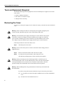
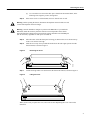
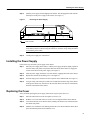
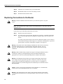
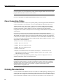
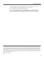
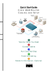
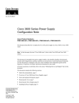
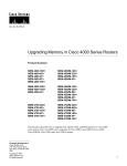
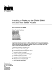
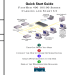
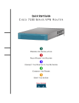
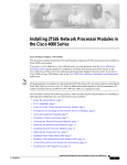
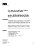
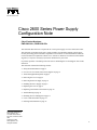
Doc. No. 78-5171-01
Cisco 2600 Series Power Supply
Configuration Note
Cisco Product Numbers:
PWR-2600-AC=, PWR-2600-DC=
This document describes how to replace the AC or DC power supply in a Cisco 2600 series router.
This document is intended for the power supply installer, who should be familiar with electronic
circuitry and wiring practices and have experience as an electronic or electromechanical technician.
Use this document in conjunction with the Cisco 2600 Series Hardware Installation Guide and the
Regulatory Compliance and Safety Information document for your router.
If you have questions or need help, refer to the section “Obtaining Service and Support” later in this
document.
This document contains the following sections:
•
•
•
•
•
•
•
•
•
•
•
•
Safety Recommendations on page 2
Overview of Cisco 2600 Series Power Supplies on page 4
Tools and Equipment Required on page 6
Removing the Cover on page 6
Removing the Power Supply on page 8
Installing the Power Supply on page 9
Replacing the Cover on page 9
Replacing Connections to the Router on page 10
Troubleshooting on page 11
Obtaining Service and Support on page 11
Cisco Connection Online on page 12
Ordering Documentation on page 12
Corporate Headquarters
Cisco Systems, Inc.
170 West Tasman Drive
San Jose, CA 95134-1706
USA
Copyright © 1998
Cisco Systems, Inc.
All rights reserved.
1
Safety Recommendations
Safety Recommendations
Follow these guidelines to ensure general safety:
•
•
•
•
Keep the chassis area clear and dust-free during and after installation.
•
•
Wear safety glasses when working under conditions that may be hazardous to your eyes.
Place the removed chassis cover in a safe place.
Keep tools away from walk areas where you or others could fall over them.
Do not wear loose clothing that may get caught in the chassis. Fasten your tie or scarf and roll up
your sleeves.
Do not perform any action that creates a potential hazard to people or makes the equipment
unsafe.
Safety Warnings
Safety warnings appear throughout this publication in procedures that, if performed incorrectly, may
harm you. A warning symbol precedes each safety warning.
Warning This warning symbol means danger. You are in a situation that could cause bodily injury. Before
you work on any equipment, be aware of the hazards involved with electrical circuitry and be familiar with
standard practices for preventing accidents.
Waarschuwing Dit waarschuwingssymbool betekent gevaar. U verkeert in een situatie die
lichamelijk letsel kan veroorzaken. Voordat u aan enige apparatuur gaat werken, dient u zich bewust
te zijn van de bij elektrische schakelingen betrokken risico's en dient u op de hoogte te zijn van
standaard maatregelen om ongelukken te voorkomen.
Varoitus Tämä varoitusmerkki merkitsee vaaraa. Olet tilanteessa, joka voi johtaa ruumiinvammaan.
Ennen kuin työskentelet minkään laitteiston parissa, ota selvää sähkökytkentöihin liittyvistä
vaaroista ja tavanomaisista onnettomuuksien ehkäisykeinoista.
Attention Ce symbole d'avertissement indique un danger. Vous vous trouvez dans une situation
pouvant causer des blessures ou des dommages corporels. Avant de travailler sur un équipement,
soyez conscient des dangers posés par les circuits électriques et familiarisez-vous avec les
procédures couramment utilisées pour éviter les accidents.
Warnung Dieses Warnsymbol bedeutet Gefahr. Sie befinden sich in einer Situation, die zu einer
Körperverletzung führen könnte. Bevor Sie mit der Arbeit an irgendeinem Gerät beginnen, seien Sie
sich der mit elektrischen Stromkreisen verbundenen Gefahren und der Standardpraktiken zur
Vermeidung von Unfällen bewußt.
Avvertenza Questo simbolo di avvertenza indica un pericolo. La situazione potrebbe causare
infortuni alle persone. Prima di lavorare su qualsiasi apparecchiatura, occorre conoscere i pericoli
relativi ai circuiti elettrici ed essere al corrente delle pratiche standard per la prevenzione di incidenti.
Advarsel Dette varselsymbolet betyr fare. Du befinner deg i en situasjon som kan føre til
personskade. Før du utfører arbeid på utstyr, må du vare oppmerksom på de faremomentene som
elektriske kretser innebærer, samt gjøre deg kjent med vanlig praksis når det gjelder å unngå ulykker.
Aviso Este símbolo de aviso indica perigo. Encontra-se numa situação que lhe poderá causar danos
físicos. Antes de começar a trabalhar com qualquer equipamento, familiarize-se com os perigos
relacionados com circuitos eléctricos, e com quaisquer práticas comuns que possam prevenir
possíveis acidentes.
2
Safety with Electricity
¡Advertencia! Este símbolo de aviso significa peligro. Existe riesgo para su integridad física.
Antes de manipular cualquier equipo, considerar los riesgos que entraña la corriente eléctrica y
familiarizarse con los procedimientos estándar de prevención de accidentes.
Varning! Denna varningssymbol signalerar fara. Du befinner dig i en situation som kan leda till
personskada. Innan du utför arbete på någon utrustning måste du vara medveten om farorna med
elkretsar och känna till vanligt förfarande för att förebygga skador.
To see translated versions of the remaining warnings in this document, refer to the Regulatory
Compliance and Safety Information document that accompanied the router.
Warning Only trained and qualified personnel should be allowed to install or replace this
equipment.
Warning Before working on a chassis or working near power supplies, unplug the power
cord on AC units; disconnect the power at the circuit breaker on DC units.
Warning Before working on a system that has an on/off switch, turn OFF the power and
unplug the power cord.
The following warning applies to routers with a DC power supply:
Warning Before performing any of the following procedures, ensure that power is
removed from the DC circuit. To ensure that all power is OFF, locate the circuit breaker
on the panel board that services the DC circuit, switch the circuit breaker to the OFF
position, and tape the switch handle of the circuit breaker in the OFF position.
Warning Ultimate disposal of this product should be handled according to all national
laws and regulations.
Caution To avoid damaging electrostatic discharge (ESD)-sensitive components, ensure
that you have discharged all static electricity from your body before opening the chassis.
Before performing procedures described in this document, review the next section,
“Safety Recommendations.”
Warning The Ethernet 10BaseT, Token Ring, serial, console, and auxiliary ports contain
safety extra-low voltage (SELV) circuits. BRI circuits are treated like telephone-network
voltage (TNV) circuits. Avoid connecting SELV circuits to TNV circuits.
Safety with Electricity
Warning Before working on equipment that is connected to power lines, remove jewelry
(including rings, necklaces, and watches). Metal objects will heat up when connected to
power and ground and can cause serious burns or weld the metal object to the terminals.
3
Overview of Cisco 2600 Series Power Supplies
Follow these guidelines when working on equipment powered by electricity:
•
Locate the room’s emergency power-OFF switch. Then, if an electrical accident occurs, you can
quickly shut the power OFF.
•
•
Before working on the system, turn OFF the power and unplug the power cord.
Disconnect all power before doing the following:
— Working on or near power supplies
— Installing or removing a router chassis or network processor module
— Performing a hardware upgrade
•
•
Do not work alone if potentially hazardous conditions exist.
•
•
Never assume that power is disconnected from a circuit. Always check.
Look carefully for possible hazards in your work area, such as moist floors, ungrounded power
extension cables, and missing safety grounds.
If an electrical accident occurs, proceed as follows:
— Use caution, and do not become a victim yourself.
— Turn off power to the system.
— If possible, send another person to get medical aid. Otherwise, determine the condition of the
victim and then call for help.
— Determine if the person needs rescue breathing or external cardiac compressions; then take
appropriate action.
Preventing Electrostatic Discharge Damage
Electrostatic discharge (ESD) can damage equipment and impair electrical circuitry. It occurs when
electronic printed circuit cards are improperly handled and can result in complete or intermittent
failures. Always follow ESD prevention procedures when removing and replacing cards. Ensure that
the router chassis is electrically connected to earth ground. Wear an ESD-preventive wrist strap,
ensuring that it makes good skin contact. Connect the clip to an unpainted surface of the chassis
frame to safely channel unwanted ESD voltages to ground. To properly guard against ESD damage
and shocks, the wrist strap and cord must operate effectively. If no wrist strap is available, ground
yourself by touching the metal part of the chassis
Caution For safety, periodically check the resistance value of the antistatic strap, which
should be between 1 and 10 megohms (Mohm).
Overview of Cisco 2600 Series Power Supplies
Figure 1 shows the typical AC power supply for Cisco 2600 series routers. The DC power supplies
look similar, but have a terminal block cover in place of the three-pronged connector for an AC
power cord.
Figure 2 shows the location of the power supply in a Cisco 2600 series router. In this case an AC
power supply is shown as an example.
Table 1 lists AC power supply specifications, and Table 2 lists DC power supply specifications.
These tables apply to all Cisco 2600 series routers.
4
Overview of Cisco 2600 Series Power Supplies
Cisco 2600 Series AC Power Supply
10346
Figure 1
AC power supply
Figure 2
Rear View of Cisco 2600 Series (Cisco 2610 Shown)
Cisco 2610
SERIAL 1
Cisco 2610
SERIAL 1
SERIAL 0
CONN
WIC
CONN 2A/S
SERIAL 0
CONN
SEE MANUAL BEFORE INSTALLATION
CONN
100-240V– 1A
50/60 Hz 47 W
WIC
2T
SEE MANUAL BEFORE INSTALLATION
W1
W0
Table 1
CONSOLE
AUX
Console
port (RJ-45)
Auxiliary port
(RJ-45)
AC Power Supply Specifications
Specification
Value
Input voltage
100 to 240 VAC, autoranging
Frequency
50 to 60 Hz
Current rating
3.0A maximum at 100 VAC, 1.5A maximum at 240 VAC
Power dissipation
72 W maximum
Table 2
H11580
LINK ETHERNET 0 ACT
Ethernet 0/0
10BaseT
port (RJ-45)
DC Power Supply Specifications
Specification
Value
Input voltage
38 to 72 VDC
Current rating
5.0A maximum at 38 VDC, 2.8A maximum at 72 VDC
Power dissipation
72 W maximum
Wire gauge for DC-input
power connections
14 AWG1
1. AWG = American Wire Gauge.
5
Tools and Equipment Required
Tools and Equipment Required
You need the following tools and equipment to remove and install power supplies in Cisco 2600
series routers:
•
•
•
Number 1 Phillips screwdriver
Wire cutters to cut cable tie-wraps
ESD-preventive wrist strap
Removing the Cover
To gain access to the power supply of Cisco 2600 series routers, you must first remove the chassis
cover.
Warning Before working on a chassis or working near power supplies, unplug the power
cord on AC units; disconnect the power at the circuit breaker on DC units.
Warning Do not touch the power supply when the power cord is connected. For systems
with a power switch, line voltages are present within the power supply even when the
power switch is off and the power cord is connected. For systems without a power switch,
line voltages are present within the power supply when the power cord is connected.
Follow this procedure to remove the chassis cover:
Step 1
Turn OFF power to the router.
Warning Do not work on the system or connect or disconnect cables during periods of
lightning activity.
Step 2
Remove all network interface cables from the rear panel.
Step 3
If you have an AC-powered router, remove the power cord.
The following warnings apply to routers with DC power supplies:
Warning Before performing any of the following procedures, ensure that power is
removed from the DC circuit. To ensure that all power is OFF, locate the circuit breaker
on the panel board that services the DC circuit, switch the circuit breaker to the OFF
position, and tape the switch handle of the circuit breaker in the OFF position.
Warning When installing the unit, the ground connection must always be made first and
disconnected last.
If you have a DC-powered router, follow these steps to remove the power cables:
6
(a)
Use a screwdriver to loosen the captive installation screws on the terminal block
cover.
(b)
Lift and remove the terminal block cover.
Removing the Cover
Use a screwdriver to remove the three power leads from the terminal block, in the
following order: negative, positive, then ground.
(c)
If the router is rack- or wall-mounted, remove it from the rack or wall.
Step 4
Warning Before opening the chassis, disconnect the telephone-network cables to avoid
contact with telephone-network voltages.
Warning Network hazardous voltages are present in the BRI cable. If you detach the
BRI cable, detach the end away from the router first to avoid possible electric shock.
Network hazardous voltages also are present on the system card in the area of the BRI port
(RJ-45 connector), regardless of when power is turned off.
Step 5
Place the router so that the front panel is facing you. Remove the screws located on top
of the cover near the front edge.
Step 6
Slide the cover away from you until the metal tabs on the side edges separate from the
chassis bottom, as shown in Figure 3.
Figure 3
Removing the Cover
POWER
RPS
ACTIVITY
Lift the front edge of the cover until it clears the front of the chassis, as shown in Figure 4.
Figure 4
Lifting the Cover
Cisco 2600
RPS
ACTIVITY
SERIES
H11659
Step 7
POWER
SERIES
H11658
Cisco 2600
When you are ready to replace the cover, refer to the section “Replacing the Cover” later in this
document.
7
Removing the Power Supply
Removing the Power Supply
This section describes how to remove the internal power supply. Although the AC power supply is
shown in the illustrations that follow, the procedure is the same for removing both the AC and DC
power supplies.
Take these steps to remove the power supply:
Step 1
Locate the six-pin connector on the system board near the front of the router, and
disconnect it. (See Figure 5.)
Note If cable tie-wraps on the harness interfere with removing the connectors, cut the
tie-wraps, being careful not to cut the power supply wires.
Figure 5
Locating the Connectors
AC power supply
H9081
Fan
Power connector
Fan connector
Remove the mounting screw that secures the power supply to the chassis. (See Figure 6.)
Set aside this screw for later use.
Figure 6
Removing the Mounting Screw
Input: 100-240VAC
Freq: 50/60 Hz
Current: 1.2-0.6A
Watts: 40W
1
0
Screw
8
H9079
Step 2
Installing the Power Supply
Step 3
Slide the power supply forward slightly in the chassis. This disengages the built-in hooks
that help secure the power supply to the chassis. (See Figure 7.)
Removing the Power Supply
H8689
Figure 7
Rear of chassis
Hooks Slots
Power supply
Note Place the removed screw and power supply in an antistatic bag. If cable tie-wraps
on the harness interfere with removing the connectors, cut the tie-wraps, being careful not
to cut into the power cables.
Step 4
Lift the power supply out of the chassis.
Installing the Power Supply
Follow these steps to install a power supply in the chassis:
Step 1
Place the power supply in the chassis, with the power supply faceplate slightly separated
from the chassis rear panel. This position allows the hooks in the chassis to engage the
cutouts in the bottom of the power supply. (See Figure 7.)
Step 2
Slide the power supply toward the rear of the chassis, engaging the hooks in the chassis.
Step 3
Replace the external rear mounting screw. (See Figure 6.)
Step 4
Insert the large power connector into the receptacle on the motherboard. (See Figure 5.)
Step 5
Using tie-wraps, fasten the power cables into a bundle that clears the edge of the chassis
and keeps the cables away from the fan. Be sure that cables to the fans are routed under
the hook in the bottom of the chassis.
Replacing the Cover
After you finish replacing the power supply, follow these steps to replace the cover:
Step 1
Place the chassis bottom so the front panel is closest to you.
Step 2
Hold the cover so the tabs at the rear of the cover are aligned with the chassis bottom.
Step 3
Lower the front of the cover onto the chassis, making sure that the cover side tabs fit under
the chassis side panels.
Step 4
Slide the cover toward the front, making sure that the cover tabs fit under the chassis back
panel, and the back panel tabs fit under the cover.
9
Replacing Connections to the Router
Step 5
Fasten the cover with the screws you set aside earlier.
Step 6
Reinstall the chassis on a rack, wall, desktop, or table.
Step 7
Reinstall network interface cables.
Replacing Connections to the Router
Warning Read the installation instructions before you connect the system to its power
source.
Note The installation must comply with the 1996 National Electric Code (NEC) and other
applicable codes.
Follow these steps to make final connections to the router:
Step 1
Replace all network connections.
Step 2
If you have an AC-powered router, plug the power cord into a 3-terminal, single-phase
power source that provides power within the acceptable range (100 to 240 VAC, 50 to
60 Hz).
If you have a DC-powered router, rewire the DC-input power supply (38 to 72 VDC) to
the terminal block using 14 AWG copper wires. The proper wiring sequence is ground to
ground, positive to positive, and negative to negative. (See Figure 8.)
Warning This product relies on the building’s installation for short-circuit (overcurrent)
protection. Ensure that a fuse or circuit breaker no larger than 120 VAC, 15A U.S.
(240 VAC, 10A international) is used on the phase conductors (all current-carrying
conductors).
Warning When stranded wiring is required, use approved wiring terminations, such as
closed-loop or spade-type with upturned lugs. These terminations should be the
appropriate size for the wires and should clamp both the insulation and conductor.
Warning The illustration shows the DC power supply terminal block. Wire the DC
power supply using the appropriate lugs at the wiring end, as illustrated. The proper
wiring sequence is ground to ground, positive to positive (line to L), and negative to
negative (neutral to N). Note that the ground wire should always be connected first and
disconnected last.
Caution Do not overtorque the terminal block captive thumbscrew or terminal block
contact screws. The recommended torque is 8.2 ± 0.4 inch-lb.
Warning After wiring the DC power supply, remove the tape from the circuit breaker
switch handle and reinstate power by moving the handle of the circuit breaker to the ON
position
10
Troubleshooting
Cisco 2600 Series DC-Input Power Supply Connections
+
-
H7477
Figure 8
Terminal
block
On/off
switch
Positive Negative
Ground
Step 3
Turn ON the power switch. The power LED on the front panel of the router should go on.)
Step 4
Verify that the OK LED on the right side of the front panel goes on after a few seconds’
delay when booting. If you have problems, see the next section, “Troubleshooting,” and
the section “Obtaining Service and Support” later in this document.
Warning Secure all power cabling when installing this unit to avoid disturbing
field-wiring connections.
Warning This equipment is intended to be grounded. Ensure that the host is connected
to earth ground during normal use.
Troubleshooting
Check the following items to help isolate problems with the power supply installation:
•
With the power switch on, is the power LED on the front panel on?
— If not, check the AC or DC input, AC or DC source, router circuit breaker, and the power
supply cable (AC) or power supply wiring (DC).
— Check the power supply connection to the motherboard.
— If the power LED is still off, the problem might be a power supply failure.
•
Does the router shut down after being on a short time?
— Check the fans. If the fans are not working, the router will overheat and shut itself down.
— If the fans are not working, check the power supply connections to the fans.
— Ensure that the chassis intake and exhaust vents are clear.
— Check the environmental site requirements in your router installation and configuration
guide.
Obtaining Service and Support
For service and support for a product purchased from a reseller, contact the reseller. Resellers offer
a wide variety of Cisco service and support programs, which are described in the section “Service
and Support” in the information packet that shipped with your chassis.
11
Cisco Connection Online
Note If you purchased your product from a reseller, you can access Cisco Connection Online
(CCO) as a guest. CCO is Cisco Systems’ primary, real-time support channel. Your reseller offers
programs that include direct access to CCO’s services.
For service and support for a product purchased directly from Cisco, use CCO.
Cisco Connection Online
Cisco Connection Online (CCO) is Cisco Systems’ primary, real-time support channel. Maintenance
customers and partners can self-register on CCO to obtain additional information and services.
Available 24 hours a day, 7 days a week, CCO provides a wealth of standard and value-added
services to Cisco’s customers and business partners. CCO services include product information,
product documentation, software updates, release notes, technical tips, the Bug Navigator,
configuration notes, brochures, descriptions of service offerings, and download access to public and
authorized files.
CCO serves a wide variety of users through two interfaces that are updated and enhanced
simultaneously: a character-based version and a multimedia version that resides on the World Wide
Web (WWW). The character-based CCO supports Zmodem, Kermit, Xmodem, FTP, and Internet
e-mail, and it is excellent for quick access to information over lower bandwidths. The WWW version
of CCO provides richly formatted documents with photographs, figures, graphics, and video, as well
as hyperlinks to related information.
You can access CCO in the following ways:
•
•
•
•
•
WWW: http://www.cisco.com
WWW: http://www-europe.cisco.com
WWW: http://www-china.cisco.com
Telnet: cco.cisco.com
Modem: From North America, 408 526-8070; from Europe, 33 1 64 46 40 82. Use the
following terminal settings: VT100 emulation; databits: 8; parity: none; stop bits: 1; and
connection rates up to 28.8 kbps.
For a copy of CCO’s Frequently Asked Questions (FAQ), contact cco-help@cisco.com. For
additional information, contact cco-team@cisco.com.
Note If you are a network administrator and need personal technical assistance with a Cisco
product that is under warranty or covered by a maintenance contract, contact Cisco’s Technical
Assistance Center (TAC) at 800 553-2447, 408 526-7209, or tac@cisco.com. To obtain general
information about Cisco Systems, Cisco products, or upgrades, contact 800 553-6387,
408 526-7208, or cs-rep@cisco.com.
Ordering Documentation
Cisco documentation and additional literature are available in a CD-ROM package, which ships with
your product. The Documentation CD-ROM, a member of the Cisco Connection Family, is updated
monthly. Therefore, it might be more current than printed documentation. To order additional copies
of the Documentation CD-ROM, contact your local sales representative or call customer service.
12
Ordering Documentation
The CD-ROM package is available as a single package or as an annual subscription. You can also
access Cisco documentation on the World Wide Web at http://www.cisco.com,
http://www-china.cisco.com, or http://www-europe.cisco.com.
If you are reading Cisco product documentation on the World Wide Web, you can submit comments
electronically. Click Feedback in the toolbar, select Documentation, and click Enter the feedback
form. After you complete the form, click Submit to send it to Cisco. We appreciate your comments.
This document is to be used in conjunction with the Cisco 2600 Series Hardware Installation Guide publication.
AccessPath, AtmDirector, the CCIE logo, CD-PAC, Centri, Centri Bronze, Centri Gold, Centri Security Manager, Centri Silver, the Cisco Capital logo, Cisco IOS, the Cisco IOS logo,
CiscoLink, the Cisco NetWorks logo, the Cisco Powered Network logo, the Cisco Press logo, ClickStart, ControlStream, Fast Step, FragmentFree, IGX, JumpStart, Kernel Proxy, LAN2LAN
Enterprise, LAN2LAN Remote Office, MGX, MICA, Natural Network Viewer, NetBeyond, NetRanger, NetSonar, Netsys Technologies, Packet, PIX, Point and Click Internetworking,
Policy Builder, RouteStream, Secure Script, SMARTnet, StrataSphere, StrataSphere BILLder, StrataSphere Connection Manager, StrataSphere Modeler, StrataSphere Optimizer, Stratm,
StreamView, SwitchProbe, The Cell, TrafficDirector, TransPath, VirtualStream, VlanDirector, Workgroup Director, Workgroup Stack, and XCI are trademarks; Empowering the Internet
Generation and The Network Works. No Excuses. are service marks; and BPX, Catalyst, Cisco, Cisco Systems, the Cisco Systems logo, EtherChannel, FastHub, FastPacket, ForeSight, IPX,
LightStream, OptiClass, Phase/IP, StrataCom, and StrataView Plus are registered trademarks of Cisco Systems, Inc. in the U.S. and certain other countries. All other trademarks mentioned
in this document are the property of their respective owners.
Copyright © 1998, Cisco Systems, Inc.
All rights reserved. Printed in USA.
9803R
13
Ordering Documentation
14