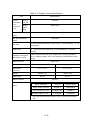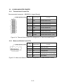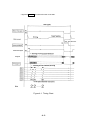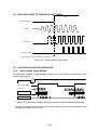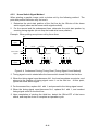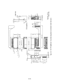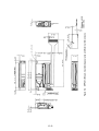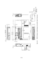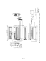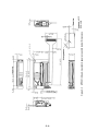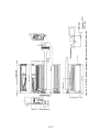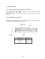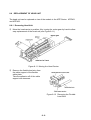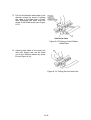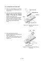
1
MTP SERIES THERMAL PRINTER MECHANISM TECHNICAL REFERENCE 39019-2352-01 Seiko Instruments Inc. MTP SERIES THERMAL PRINTER MECHANISM TECHNICAL REFERENCE Document Number 39019-2352-01 January 1995 Copyright 1995 by Seiko Instruments Inc. All rights reserved. Seiko Instruments Inc. (SII) has prepared this manual for use by SII personnel, licensees, and customers. The information contained herein is the property of SII and shall not be reproduced in whole or in part without the prior written approval of SII. SII reserves the right to make changes without notice to the specifications and materials contained herein and shall not be responsible for any damages (including consequential) caused by reliance on the materials presented, including but not limited to typographical, arithmetic, or listing errors. SII is a trademark of Seiko Instruments Inc. PREFACE This reference manual describes the specifications and basic operating procedures for the MTP Series Themal Printer Mechanisms. Read it thoroughly so that you are able to use the MTP Series Themal Printer Mechanisms properly. Fully investigate the intellectual proprietary rights of the sample circuits designed in this manual before using. iii iv TABLE OF CONTENTS Section Page CHAPTER 1 FEATURES CHAPTER 2 SPECIFICATIONS 2.1 PART NUMBER....................................................................................... 2-1 2.2 GENERAL SPECIFICATIONS................................................................. 2.2.1 Character Printers ..................................................................... 2.2.2 Graphic Printers......................................................................... 2-2 2-2 2-4 2.3 MOTOR DRIVE CHARACTERISTICS..................................................... 2-6 2.4 TG (TACHO-GENERATOR) OUTPUT CHARACTERISTICS ................. 2-9 2.5 HOME SWITCH....................................................................................... 2-10 2.6 THERMAL PRINT HEAD ......................................................................... 2.6.1 Head Specifications................................................................... 2.6.2 Head Applied Energy Correction ............................................... 2.6.3 Head Activation Pulse Width ..................................................... 2.6.4 Control of Printing Pulse Width ................................................. 2.6.5 Intialization................................................................................. 2.6.6 Paper Feeding ........................................................................... 2-11 2-11 2-12 2-12 2-13 2-14 2-14 CHAPTER 3 PIN ASSIGNMENT 3.1 B HEAD-MOUNTED PRINTER ............................................................... 3.1.1 Thermal Head Control Pin ......................................................... 3.1.2 Motor and Switch Control Pin .................................................... v 3-1 3-1 3-2 Section Page 3.2 G HEAD-MOUNTED PRINTER............................................................... 3.2.1 Thermal Head Control Pin......................................................... 3.2.2 Motor and Switch Control Pin.................................................... 3-3 3-3 3-3 3.3 E HEAD-MOUNTED PRINTER ............................................................... 3.3.1 Thermal Head Control Pin......................................................... 3.3.2 Motor and Switch Control Pin.................................................... 3-4 3-4 3-4 CHAPTER 4 TIMING CHART 4.1 TIMING CHART ...................................................................................... 4-1 4.2 DETAILED CHART OF PRINTING START TIMING ............................... 4-3 4.3 CONTINUOUS PRINTING OPERATION ................................................ 4.3.1 Home Switch Signal Method ..................................................... 4.3.2 Home Switch Signal Method ..................................................... 4-3 4-3 4-4 CHAPTER 5 APPEARANCE AND DIMENSIONS CHAPTER 6 SAMPLE CIRCUIT BLOCK DIAGRAM CHAPTER 7 DESIGNING AND HANDLING PRECAUTIONS 7.1 7.2 DESIGN PRECAUTIONS........................................................................ HANDLING PRECAUTIONS ................................................................... 7-1 7-1 CHAPTER 8 DESIGN OF PERIPHERAL DEVICES 8.1 MOUNTING THE PRINTER .................................................................... 8.1.1 MTP102 Printer ......................................................................... 8.1.2 MTP201 and 401 Printers ......................................................... 8-1 8-1 8-2 8.2 MOUNTING THE PAPER CUTTER ........................................................ 8-4 8.3 MOUNTING A ROLL HOLDER FOR HEAD SENSITIVE PAPER........... 8-5 8.4 THERMAL PAPER TAKE-UP DEVICE ................................................... 8-6 vi 8.5 FLEXIBLE CABLE ................................................................................... 8.5.1 Connecting and Fixing the Flexible Cable Terminal .................. 8.5.2 Bend Radius of Flexible Cable .................................................. 8-7 8-7 8-7 8.6 REPLACEMENT OF HEAD UNIT............................................................ 8-8 8.6.1 Removing Head Unit ................................................................. 8-8 8.6.2 MOUNTING THE HEAD UNIT .................................................. 8-10 TABLES Table 2-1 2-2 2-3 Page Character Printer Specifications .............................................................. Graphic Printer Specifications ................................................................. TG Output ................................................................................................ 2-2 2-4 2-9 FIGURES Figure Page 2-1 2-2 2-3 2-4 2-5 2-6 2-7 2-8 2-9 Motor Drive Characteristics...................................................................... Motor Drive Signal Timing........................................................................ Sample Motor Drive Circuit ...................................................................... Sample TG waveform shaping circuit ...................................................... TG Timing Signal ..................................................................................... OFF-to-ON Detection............................................................................... ON-to-OFF Detection............................................................................... Pulse Width Control ................................................................................. Sample Pulse Width Control Circuit......................................................... 2-6 2-7 2-8 2-9 2-9 2-10 2-10 2-13 2-14 3-1 3-2 Thermal Head Control Pin Assignment (B Head-mounted Printer) ......... Motor and Switch Control Pin Assignment (B Head-mounted Printer, MTP102) ........................................................ Motor and Switch Control Pin Assignment (B Head-mounted Printer, MTP201 and MTP401)................................... Thermal Head Control Pin Assignment (G Head-mounted Printer) ......... Motor and Switch Control Pin Assignment (G Head-mounted Printer) .... Thermal Head Control Pin Assignment (E Head-mounted Printer) ......... Motor and Switch Control Pin Assignment (E Head-mounted Printer)..... 3-1 3-3 3-4 3-5 3-6 3-7 vii 3-2 3-2 3-3 3-3 3-4 3-4 Figure Page 4-1 4-2 4-3 4-4 Timing Chart............................................................................................ Printing Start Timing Chart ...................................................................... Continuous Printing Timing Chart (Home Switch Detection Method) ...... Continuous Printing Timing Chart (Timing Signal Count Method) ........... 4-2 4-3 4-3 4-4 5-1 5-2 5-3 5-4 5-5 5-6 MTP102 (B head-mounted) Appearance and External Dimensions........ MTP201 (B head-mounted) Appearance and External Dimensions........ MTP201 (E head-mounted) Appearance and External Dimensions........ MTP401 (B head-mounted) Appearance and External Dimensions........ MTP201 (G head-mounted) Appearance and External Dimensions ....... MTP401 (G head-mounted) Appearance and External Dimensions ....... 5-2 5-3 5-4 5-5 5-6 5-7 6-1 6-2 Sample Circuit Block Diagram (B Head-mounted Printer)....................... Sample Circuit Block Diagram (G Head-mounted Printer) ..................... 6-2 6-3 8-1 8-2 8-3 8-4 8-5 8-6 8-7 8-8 8-9 8-10 8-11 8-12 8-13 8-14 8-15 8-16 8-17 8-19 8-18 MTP102 Printer (Back) ............................................................................ Mounting with Screws (MTP102 Printer) ................................................. Mounting without Screws (MTP102 printer)............................................. MTP201 and 401 Printers (Back) ............................................................ Mounting with Screws (MTP201 and 401 Printer) ................................... Mounting without Screws (MTP201 and 401 Printer) .............................. Mounting the Paper Cutter ...................................................................... Mounting a Roll Holder for Heat Sensitive paper .................................... Roll without Core ..................................................................................... Bend Radius of Flexible Cable ................................................................ Moving the Head Carrier ......................................................................... Removing the Flexible Lead Wire ........................................................... Pulling out the Flexible Cable Plate......................................................... Pulling Out the Head Unit ........................................................................ Inserting the Head Unit Terminal............................................................. Rotating the Head Portion of the Unit...................................................... Sliding the Head along the Guide of the Head Carrier ............................ Inserting the Flexible Cable ..................................................................... Pushing the Flexible Cable PLate .......................................................... 8-1 8-1 8-2 8-2 8-3 8-3 8-4 8-5 8-5 8-7 8-8 8-8 8-9 8-9 8-10 8-10 8-11 8-11 8-11 viii CHAPTER 1 FEATURES The MTP Series Line Thermal Printer Mechanism is a series of compact, thermal printers designed to meet the demand for small, low cost units. It can be used in adding machines, measuring instruments and analyzers, office machines, medical apparatus, and data terminal devices. The MTP Series Line Thermal Printer Mechanism has the following features: • Low cost • Maintenace-free • High quality printing • Battery drive • Silent, nonimpact system • Designed for versatile applications • High reliability 1-1 1-2 CHAPTER 2 SPECIFICATIONS 2.1 PART NUMBER (1) Character printers − MTP ➀ * ➀ : Base model code ➁ : Characters per line* ➁ ➂ ➂ : Print head type used Maximum number of characters per line based on character matrix in General Specifications. (2) Graphic printers − MTP ➀ ➂ ➀ : Base model code ➂ : Print head type used ➃ : Maximum number of dots per row per line ➃ 2-1 2.2 GENERAL SPECIFICATIONS 2.2.1 Character Printers Table 2-1 Character Printer Specifications Item Specifications Base model code Model MTP102 MTP102-13B MTP201 MTP102-16B Printing metod Printing direction Dots per line (H × W / line) Paper feed pitch (H × W) Characters per line MTP401-40B left to right with respect to the direction the paper is fed. 7 dots 7 dots × 89 dots 0.35mm × 0.30mm 7 dots × 110 dots 0.35mm 7 dots × 138 dots 0.35mm × 0.24mm 7 dots × 166 dots 0.35mm × 0.33mm × 0.28mm × 278 dots 0.35mm × 0.24mm 7 × 5 dot matrix (H × W) (H × W) MTP201-24B Thermal serial dot printing Character matrix Character size MTP201-20B MTP401 2.4mm × 1.5mm 13 dot (2 dot spaces) 2.4mm 2.4mm × 1.2mm 2.4mm × 1.6mm × 1.4mm 2.4mm × 1.2mm 16 dot (2 dot 20 dot (2 dot 24 dot (2 dot 40 dot (2 dot spaces) spaces) spaces) spaces) Printing width 26.7mm 26.4mm 45.9mm 46.0mm 66.7mm Printing speed Approx.1.5 Approx.1.2 Approx.1.0 Approx.0.9 Approx.0.5 line / s line / s line / s line / s line / s (room temperature, 5.0V) Paper feed pitch Head activation timting detection Home position detection 3.8mm Via a tachogenerator Via a mechanical switch Operating voltage DC5.0V±1.0V range 2-2 Table 2-1 Character Printer Specifications Item Current consumption (room temperature, 5.0V) (continued) Specifications during 3.2A max. printing during 250mA max. paper feed Operating temperature 0 to 50°C range Storage temperature -40 to 60°C range Life span 5 hundred thousand lines (5.0V rated enrgy, room temperature, “8” full line printing) -6 Failure rate 10 / line or less (5.0V rated enrgy, room temperature, “8” full line printing) Operating noise (room 70dB or less (back ground noise: 40dB or less, measuring distance: temperature, 5.0V) 15cm, weighing: JIS A curve, dynamic characteristics : SLOW range) Paper feed force 20g or more Paper hold force 50g or more Dimensions 50g or more 100g 48×31×13.8mm 70×34×14.4mm 91.5×35.5 ×20mm Approx. 35g Approx. 40g Approx. 50g 38 0−1 mm 58 0−1 mm 80 0−1 mm (WDH) Weight Paper width 65±5µm Paper thickness Recommended thermal paper Maker /Sensitivity Normal High sensitivity Nippon Paper Industries TP50KS-A TF50KS-E2C Honshu Paper Co., Ltd. FH65BX-14N FH65BU-2 F-200U7N5 F-200U9W3 Mitsubishi Paper Co., Ltd. 2-3 2.2.2 Graphic Printers Table 2-2 Graphic Printer Specifications Item Specifications Base model code Model MTP201 MTP201-G128 MTP201-G166 MTP401-G256 MTP201-G280 Printing metod Printing direction Dots per line (H×W / line) Paper feed pitch (H×W) MTP401 Thermal serial dot printing left to right with respect to the direction the paper is fed. 8 dots 8 dots ×128 dots 0.35mm 8 dots ×166 dots 0.35mm ×0.35mm 0.35mm ×0.28mm Character matrix 8 dots ×256 dots ×0.26mm ×280 dots 0.35mm ×0.24mm 7×5 dot matrix (H×W) Character size (H×W) Characters per line 2.4mm 18 dot (2 dot Printing speed (room temperature, 5.0V) detection Home position detection ×1.3mm 2.4mm ×1.2mm 36 dot (2 dot 40 dot (2 dot spaces) spaces) spaces) 44.7mm 46.0mm 66.6mm 67.2mm Approx.0.9 Approx.0.9 Approx.0.5 Approx.0.5 line / s line / s line / s line / s Paper feed pitch Head activation timing 2.4mm ×1.4mm 24 dot (2 dot spaces) Printing width 2.4mm ×1.7mm 2.8mm Via a tachogenerator Via a mechanical switch DC5.0V±1.0V Operating voltage range 2-4 Table 2-2 Graphic Printer Specifications Item Current consumption (room temperature, 5.0V) Specifications during 3.2A max. printing during 250mA max. paper feed Operating temperature 0 to 50°C range Storage temperature -40 to 60°C range Life span 5 hundred thousand lines (5.0V rated energy, room temperature, “8” full line printing) -6 Failure rate Operating noise (room temperature, 5.0V) 10 / line or less (5.0V rated enrgy, room temperature, “8” full line printing) 70dB or less (back ground noise : 40dB or less, measuring distance: 15cm, weighing network: JIS A curve,dynamic characteristics: SLOW range) Paper feed force 20g or more Paper hold force Dimensions (W×D×H) Weight Paper width 50g or more 100g or more 70×34×14.4mm 91.5×35.5×20mm Approx. 40g Approx. 50g 58-10mm 80-10mm 65±5µm Paper thickness Recommended thermal paper Maker /Sensitivity Normal High sensitivity Nippon Paper Industries TP50KS-A TF50KS-E2C Honshu Paper Co., Ltd. FH65BX-14N FH65BU-2 F-200U7N5 F-200U9W3 Mitsubishi Paper Co., Ltd. * Only high-sensitivity thermal papers can be used with the MTP20116E. 2-5 2.3 MOTOR DRIVE CHARACTERISTICS The motor is the power source for head movement and paper feed. Through the application of DC voltage to the motor, the head automatically moves back and forth, and paper fed on its return; therefore, there is no need to reverse the motor. Motor terminal voltage Motor power consumtion During printing 5.0±1.0 VDC During paper feeding Commencing movement Ceasing movement 170 mA max. (room temperature, room humidity, 5.0 VDC) 250 mA max. (room temperature, room humidity, 5.0 VDC) 700 mA max. (room temperature, room humidity, 5.0 VDC) 500 mA max. (room temperature, room humidity, 5.0 VDC) Starting 25 ms max. (when applying the brake) Paper feeding Printing 250mA max. 170mA max. Time 500mA max. Current 700mA max. (1) (2) Stopping Figure 2-1 Motor Drive Characteristics 2-6 (3) Motor stop signal Stop the motor drive signal within 1 ms after detecting a home switch “OFF” (100 to 250 µs) signal, and input a motor stop signal of at least 25 ms. 100∼250µs ON Home switch signal OFF Motor drive signal 1 ms max. Motor stop signal 25 ms min. * See Section 2.5, Home Switch, for home switch signal. Figure 2-2 Motor Drive Signal Timing 2-7 Vcc 270Ω M 300Ω 3kΩ IN 30kΩ 2kΩ * When using Sanyo Electric’s LB1256 as the thermal head and motor drive IC, because of a built-in motorstop circuit, a motor stop signal is not required. Figure 2-3 Sample Motor Drive Circuit 2-8 2.4 TG (TACHO-GENERATOR) OUTPUT CHARACTERISTICS The TG is a signal generator directly connected to the motor, that generates false sine waves of two cycles per 1 turn of the motor. These waves are converted by a waveform shaping circuit into rectangular wave signals, which are used as a pulse impression timing signal for the thermal head. (1) TG output Table 2-3 TG Output (2) 4 to 6V 5V Output voltage (Vp-p) 2.0 to 7.0 3.5 to 6.0 Period (ms) 2.5 to 6.5 3.0 to 5.0 Sample TG waveform shaping circuit Vcc 180kΩ 180kΩ TG Timing signal 2SC1740R 560P 1SS133 Figure 2-4 Sample TG waveform shaping circuit TG signal Timing signal * Generation of the timing signals depends on the user. Figure 2-5 TG Timing Signal 2-9 2.5 HOME SWITCH The home switch is a push-open type mechanical switch, which switches “OFF” when the head is at the home position (left end). The switch has two functions. The first is to detect the home position when the head stops there. Upon returning to the home postion, the home switch switches from “ON” to “OFF”, and brakes are applied to stop the motion of the print head. The second function is it is used as reference point for starting the counting of the print timing signals. As the head begins to move to the right from the home position, the home switch switches from “OFF” to “ON”, at which point counting of the print timing signal begins (TG signals after waveform shaping). (1) Contact resistance 5 Ω max. (measuring current: 50 µA) (2) Current 1.0 mA max. (5.0 VDC) (3) OFF-to-ON detection 100µs 2ms Figure 2-6 OFF-to-ON Detection This swtich has the characteristics that the ON state exists for more than 100 µs within 2 ms of when the home switch switches from OFF-to-ON. Do not detect the switch until after 1-line has printed after detection of the first ON detection. (4) ON-to-OFF detection 450µs 2ms Figure 2-7 ON-to-OFF Detection This switch has the characteristics that the OFF state exists for more than 450 µs within 2 ms of when the home switch switches from ON-to-OFF. Do not detect the switch for 10 ms after detection of OFF. 2 - 10 2.6 THERMAL PRINT HEAD Because the thermal print head in the MTP Series is a thin film type with high thermal efficiency, it has an excellent print quality. The CPU determines which vertically placed heating units to energize, and drives them with the thermal head driver (transistor array). 2.6.1 Head Specifications Type of Head B Head Heating unit size Dot 1 G Head Dot 1 0.3 Dot 2 Dot 3 0.3 Dot 2 0.05 Dot 3 0.05 Dot 4 Dot 4 2.4 Dot 5 Dot 5 Dot 6 Dot 6 Dot 7 Dot 7 0.26 2.75 Dot 8 0.26 Resistance value* A rank 15.3±1Ω 17.6±1Ω B rank 14.0±1Ω 16.0±1Ω C rank 12.7±1Ω 14.4±1Ω Head applied voltage Peak current DC5.0±1V (at FPC terminal) 3.0Amax. 3.0Amax. Head applied Rated High sensitive High sensitive energy thermal paper (in simultaneous drive of all dots ar 5.0 VDC) thermal paper 2.30mJ (24°C, 5.0V) 2.30mJ Standard thermal Standard thermal paper paper 2.50mJ Max. * 3.00mJ 2.50mJ 3.00mJ The resistance value of each dot in the same head may have a 5% dispersion rate, and the average values are indicated on the rank table above. Rank symbols are printed on the FPC. 2 - 11 2.6.2 Head Applied Energy Correction Use the Applied Energy Correction Formula below to correct for when the power voltage and ambient temperature fluctuation during operation (see sample pulse width control circuit). Applied energy correction formula T -T 0 0+V E = V E0 (1+ ) 2V 100 E: V: T: E0: Applied energy (mJ) FPC terminal voltage (V) Temperature (°C) Rated energy (mJ) High sensitive thermal paper B head G head 2.3mJ 2.3mJ Standard thermal 2.5mJ paper V0: Rated voltage (5.0V) T0: Room temperature (24°C) 2.6.3 2.5mJ Head Activation Pulse Width To ensure high quality printing with the MTP Series, the thermal head activation pulse width must be set according to the head drive voltage and the head resistance. Pulse width calculation formula RE t = 2 V t: R: Pulse width for applying rated energy (ms) Head resistance (Ω) B head G head A rank 15.3Ω 17.6Ω B rank 14.0Ω 16.0Ω C rank 12.7Ω 14.4Ω E: Applied energy (mJ) V: FPC terminal voltage (V) Note: Procedure forpulsewidth adjustment ➀ Minimize pulse width. ➁ Activate the thermal head with a checked pattern. ➂ Measure the head terminal voltage by using a synchroscope. ➃ Gradually adjust applied pulse width, which is calculated by using the pulse width calculation formula. 2 - 12 2.6.4 Control of Printing Pulse Width Superior print quality can be maintained by controlling the print pulse width by the print pulse width control circuit. This is an oscillating circuit in which the frequency varies depending upon the voltage and ambient temperature, and provides a specified pulse width by counting a certain number of pulses with the CPU. The leading edge of the pulse is synchronized with the timing signal. Control the leading edge of the pulse by the pulse width control circuit to obtain the rated applied energy. Timing signal 0.8t t t Head drive signal Do not exceed maximum specified energy. Figure 2-8 Pulse Width Control • Avoid continuous energizing. • When driving the same dot successively, reduce the applied energy to 80% of the rated applied energy and slow down the rise of the head driving signal. 2 - 13 Oscillator output 4069UB 820p 100kΩ 150kΩ VR 50kΩ 22kΩ 22kΩ 2SC 1740R 1SS133 22kΩ Print pulse width 1 2 3 4 5 18 19 20 Oscillator output Head drive signal (Example: 20 -pulse count) * The compensation circuits for temperature and voltage are included. * Adjust an oscillating frequency with VR to obtain the proper pulse width in 20 counts at the normal temperature. * A print pulse width is made by counting the above oscillator output with the CPU. Figure 2-9 Sample Pulse Width Control Circuit 2.6.5 Initialization Feed out the paper by one line and stop the print head at the home position after turning on the power. 2.6.6 Paper Feeding Paper is fed automatically upon input of a motor drive signal. After paper is fed, the head must stop always at the home position. 2 - 14 CHAPTER 3 PIN ASSIGNMENT 3.1 B HEAD-MOUNTED PRINTER 3.1.1 Thermal Head Control Pin Recommended connector: HBLB8S-1J (Japan Burndy) Pin Number Signal Name Function 1 Dot 1 Thermal head 1st dot 2 Dot 2 Thermal head 2nd dot 3 Dot 3 Thermal head 3rd dot 4 Dot 4 Thermal head 4th dot 5 Dot 5 Thermal head 5th dot 6 Dot 6 Thermal head 6th dot 7 Dot 7 Thermal head 7th dot 8 H-COM Thermal head common (+5V) Figure 3-1 Thermal Head Control Pin Assignment (B Head-mounted Printer) 3-1 3.1.2 (1) Motor and Switch Control Pin MTP102 Recommended connector: HBLB6S-1J (Japan Burndy) Pin Number Signal Name Function 1 HS 2 HS 3 TG 4 TG 5 M- Motor minus 6 M+ Motor plus (+5V) Home switch, GND for VCC Tachogenerator, GND for VCC Figure 3-2 Motor and Switch Control Pin Assignment (B Head-mounted Printer, MTP102) (2) MTP201 and MTP401 Pin Number Signal Name Function 1 M+ Motor plus (+5V) 2 M- Motor minus 3 TG Tachogenerator 4 HS ⋅ TG-COM Home switch ⋅ Tachogenerator common (GND) 5 HS Home switch Figure 3-3 Motor and Switch Control Pin Assignment (B Head-mounted Printer, MTP201 and MTP401) 3-2 3.2 G HEAD-MOUNTED PRINTER 3.2.1 Thermal Head Control Pin Recommneded connector: HBLB9S-1J (Japan Burndy) Pin Number Signal Name Function 1 Dot 1 Thermal head 1st dot 2 Dot 2 Thermal head 2nd dot 3 Dot 3 Thermal head 3rd dot 4 Dot 4 Thermal head 4th dot 5 Dot 5 Thermal head 5th dot 6 Dot 6 Thermal head 6th dot 7 Dot 7 Thermal head 7th dot 8 Dot 8 Thermal head 8th dot 9 H-COM Thermal head common (+5V) Figure 3-4 Thermal Head Control Pin Assignment (G Head-mounted Printer) 3.2.2 Motor and Switch Control Pin Pin Number Signal Name Function 1 M+ Motor plus (+5V) 2 M- Motor nimus 3 TG Tachogenerator 4 HS ⋅ TG-COM Home switch ⋅ Tachogenerator common (GND) 5 HS Home switch Figure 3-5 Motor and Switch Control Pin Assignment (G Head-mounted Printer) 3-3 3.3 3.3.1 E HEAD-MOUNTED PRINTER Thermal Head Control Pin Recommended connector: 52045-1710 (Molex Japan) Pin Number Signal Name Function 1 Dot 1 Thermal head 1st dot 2 Dot 2 Thermal head 2nd dot 3 Dot 3 Thermal head 3rd dot 4 Dot 4 Thermal head 4th dot 5 Dot 5 Thermal head 5th dot 6 Dot 6 Thermal head 6th dot 7 Dot 7 Thermal head 7th dot 8 Dot 8 Thermal head 8th dot 9 Dot 9 Thermal head 9th dot 10 Dot 10 Thermal head 10th dot 11 Dot 11 Thermal head 11th dot 12 Dot 12 Thermal head 12th dot 13 Dot 13 Thermal head 13th dot 14 Dot 14 Thermal head 14th dot 15 Dot 15 Thermal head 15th dot 16 Dot 16 Thermal head 16th dot 17 H-COM Thermal head common (+5 V) Figure 3-6 Thermal Head Control Pin Assignment (E Head-mounted Printer) 3.3.2 Motor and Switch Control Pin Recommended connector: 5597-06CPB (Molex Japan) Pin Signal Name Function Number 1 HS 2 HS 3 M- 4 TG 5 TG 6 M+ Home switch, GND for Vcc Motor minus Tachogenerator, GND for Vcc Motor plus (+5V) Figure 3-7 Motor and Switch Control Pin Assignment (E Head-mounted Printer) 3-4 CHAPTER 4 TIMING CHART 4.1 TIMING CHART Figure 4-11 shows the timing chart when using a B-head mounted printer. The number of the head drive signal depends on the type of thermal head mounted on the printer. 4-1 * Signals in are issued from the circuit side. Figure 4-1 Timing Chart 4-2 4.2 DETAILED CHART OF PRINTING START TIMING ON OFF Home switch signal TG signal 1 2 3 4 5 Timing signal Head drive signal * Start printing from the second pulse of timing signals. Figure 4-2 Printing Start Timing Chart 4.3 CONTINUOUS PRINTING OPERATION 4.3.1 Home Switch Signal Method The print start position is determined for each line on the basis of the ON-rise of the home switch signal. Motor drive signal ON OFF ON Home switch signal OFF TG signal Timing signal 1 2 3 4 5 1 2 3 4 5 6 Head drive signal Figure 4-3 Continuous Printing Timing Chart (Home Switch Detection Method) • Due to a detection error of the home switch signal, the print start position may deviate by a maximum of 1 dot. 4-3 4.3.2 Home Switch Signal Method When printing a graphic image, print a picture unit by the following method. The print start position deviation may not occur. 1. Determine the print start position of the first line by the ON-rise of the home switch signal (same as the home switch signal method). 2. For the second and the subsequent lines, determine the print start postion by counting timing signals (do not stop the head at its home postion). Example: When printing one picture unit by three lines ON Motor drive signal OFF Home switch 2nd line 1st line ON 3rd line OFF signgal Ignored 1 2 3 N 1 2 3 Ignored N 1 2 3 Timing signal Figure 4-4 Continuous Printing Timing Chart (Timing Signal Count Method) Timing signal count is started after the home switch turned ON for the first line. When the timing signal count becomes N+1, the head completes one stroke, and returns to the position of timing signal count 1 on the first line. At this point, ignore the home switch signal. For the second line, replace N+1 with 1, and proceed to the timing signal count. When the timing signal count becomes N+1, replace N+1 with 1, and conduct timing signal count for the third line. Upon completion of printing the third line, detect the ON-to-OFF of the home switch, and stop the motor to complete an operation cycle. 4-4 N is as shown below: Part Number N Part Number N MTP102-13B 160 MTP201-G128 276 -16B 200 -G166 276 MTP201-20B 230 MTP401-G256 450 -24B 276 -G280 450 MTP401-40B 450 4-5 4-6 CHAPTER 5 APPEARANCE AND DIMENSIONS Figures 5-1 to 5-6 shows the appearance and external dimensions of the MTP Series printer mechanisms. 5-1 5-2 Figure 5-1 MTP102(B head-mounted) Appearance and External Dimensions 5-3 Figure 5-2 MTP201(B head-mounted) Appearance and External Dimensions 5-4 Figure 5-3 MTP201(E head-mounted) Appearance and External Dimensions 5-5 Figure 5-4 MTP401(B head-mounted) Appearance and External Dimensions 5-6 Figure 5-5 MTP201(G head-mounted) Appearance and External Dimensions 5-7 Figure 5-6 MTP401(G head-mounted) Appearance and External Dimensions 5-8 CHAPTER 6 SAMPLE CIRCUIT BLOCK DIAGRAM Figures 6-1 and 6-2 shows the samples of the circuit block diagrams. 6-1 6-2 Figure 6-1 Sample Block Diagram(B Head-mounted Printer) 6-3 Figure 6-2 Sample Block Diagram(G Head-mounted Printer) 6-4 CHAPTER 7 DESIGNING AND HANDLING PRECAUTIONS To maintain the performance of the MTP Series and to prevent future problems from occuring, observe the following precautions. 7.1 DESIGN PRECAUTIONS ➀ Do not apply an energy source that is too high. If too much energy is applied to the thermal head, it may overheat and become damaged. Always use the printer with the specified pulse width. ➁ Stop activating to the motor if the thermal head does not return to the home position because of a paper jam (the home switch signal detection is not executed). ➂ if the MTP Series is used at extremely high temperature or at high humidity, the thermal head may be electrolytically corroded. To prevent the thermal head from being electorlytically corroded: • • 7.2 Keep the thermal paper away from the ground. Turn OFF the VP power supply when not printing. HANDLING PRECAUTIONS ➀ If any paper other than that specified is used, the high print quality and long life of the thermal head can not be guaranteed. Possible problems that may occur: • Poor print quality due to low-sensitivity paper • Abrasion of the thermal head due to paper surface which is too rough • Print fading due to low print preservation • Poor print quality due to paper trash attachment 7-1 ➁ Stop the thermal head at the home position; otherwise, the platen may become deformed resulting in poor print quality. ➂ Do not print without paper; otherwise, the platen or thermal head may become damaged. ➃ Do not damage the platen by removing paper when a paper jam occurs. ➄ Cut the edge of the paper so that the corners of the paper are square (90°); otherwise, a paper jam may occur. ➅ Unload paper in the direction in which the paper is normally fed. If paper is unloaded in the reverse direction, the paper feed mechanism may become damaged. ➆ Do not use a thermal paper roll whose core and the paper are attached; otherwise, the paper will lock causing the paper feed to suddenly increase the amount fed resulting in damage to the paper feed mechanism. ➇ Remove the debris on the surface of the paper; otherwise, a paper jam may occur. 7-2 CHAPTER 8 DESIGN OF PERIPHERAL DEVICES 8.1 MOUNTING THE PRINTER The mounting procedure for MTP Series printers differs somewhat between the MTP102 and the other printers in the serires. Mount the printer so that it is not warped or distorted in any way. 8.1.1 MTP102 Printer The MTP102 is provided on its back two dowels and two holes diagonally for mounting the printer (see Figure 8-1). ➀ When mounting with screws Mount the printer by tightening the tapping screws from under the mounting base. In this case, the dowels are used as a reference for positioning (see Figure 8-2). Figure 8-1 MTP102 Printer (Back) Figure 8-2 8-1 Mounting with Screws (MTP102 Printer) ➁ When mounting without screws Using the dowels and the φ2 mm holes on the back of the printer as reference for positioning, fix the printer by pressing the eaves on both sides of the upper portion of the printer (see Figure 8-3). Do not push on the eaves at the motor end. 8.1.2 Figure 8-3 Mounting without Screws (MTP102 printer) Figure 8-4 MTP201 and 401 Printers (Back) MTP201 and 401 Printers The MTP201 and 401 printers are provided with φ2.2 mm mounting holes at the two corners of the printer (see Figure 8-4). 8-2 ➀ When mounting with screws With the φ2.2 mm holes at the corners of the printer as a reference for positioning, fix the printer on the printer base by tightening the tapping screws from the top of the printer (see Figure 8-5). Figure 8-5 Mounting with Screws (MTP201 and 401 Printer) Figure 8-6 Mounting without Screws (MTP201 and 401 Printer) ➁ When mounting without screwsWith the φ2.2 mm holes as a reference for positioning, fix the printer by pressing the eaves on both sides of the upper portion of the printer. 8-3 8.2 MOUNTING THE PAPER CUTTER Design the paper cutter so that the cutter tip is located over the paper outlet so that it does not interrupt the paper flow (see Figure 8-7). Design any peripheral devices so that the paper does not re-enter the printer. Figure 8-7 Mounting the Paper Cutter Examples of improper designs: This type of design may cause improper contact between the platen and the thermal head leading to deterioration in the quality of the print. Design conditions: This type of design may cause damage to the paper surface. Furthermore, it may apply excessive force on the thermal head when cutting the paper. The paper-hold tension indicates the opposing force produced when the paper is pulled out through the outlet. It is expressed as “X g or more” in the specifications. As this is a specification for the printer, design the paper cutter so that paper must be cut with an opposing force of “X g or less”. 8-4 8.3 MOUNTING A ROLL HOLDER FOR HEAD SENSITIVE PAPER Design the roll holder to the following specifications: 1) No sideways deviation between holder and inlet. 2) Less than 2mm between holder and the sides of the roll. 3) The holder does not touch the sides of the roll. 4) The horizontal axis of the roll in the holder is parallel with the inlet (see Figure 8-8). Example of improper design: • Figure 8-8 Mounting a Roll Holder for Heat Sensitive paper Roll without core 1) The roll rolls easily. 2) The roll remains securely in the holder. Design conditions: The paper feed tension is expressed as “X g or more” in the specifications. Since this is a specification for the printer feed, design the roll holder so that the paper tension is “X g or less”. Figure 8-9 Roll without Core 8-5 8.4 THERMAL PAPER TAKE-UP DEVICE Take into consideration the following items when designing the thermal paper takeup device. 1) After printing, the paper must be taken up without being pulled taut. 2) Even when paper guides have attached as shown below, if the thermal paper is pulled taut, correct contact between the thermal head and the thermal paper can not be obtained and printing will be adversely affected. <Improper thermal paper take-up device> <Proper thermal paper take-up device> 8-6 8.5 FLEXIBLE CABLE 8.5.1 Connecting and Fixing the Flexible Cable Terminal Use and FPC (Flexible Printed Circuit) connector to connect and fix the flexible cable terminal. Refer to the external view of each printer for the mounting position of the FPC connector. 8.5.2 Bend Radius of Flexible Cable Design the case of peripheral device to provide for a minimum radius of at least 5R (mm) at the point where the flexible cable bends. Base Model a (mm) MTP 102 5.3 MTP 201 5.3 MTP 401 8.0 Figure 8-10 Bend Radius of Flexible Cable 8-7 8.6 REPLACEMENT OF HEAD UNIT The head unit can be replaced on two of the models in the MTP Series: MTP401 and MTP402. 8.6.1 Removing Head Unit ➀ Move the head carrier to position A by turning the motor gear by hand to allow easy replacement of the head unit (see Figure 8-11). Figure 8-11 Moving the Head Carrier ➁ Remove the flexible lead wire from the cable support of the flexible cable plate. Take the adhesive off of the cable support with tweezers. Figure 8-12 Removing the Flexible Lead Wire 8-8 ➂ Pull out the flexible cable plate in the direction shown by arrow A holding the edge of the plate with a finger, then disengage the plate from the dowel of the head carrier (see Figure 8-13). Figure 8-13 Pulling out the Flexible Cable Plate ➃ Holding both sides of the head unit with your fingers, pull out the head unit in the direction shown by arrow B (see Figure 8-14). Figrue 8-14 Pulling Out the Head Unit 8-9 8.6.2 MOUNTING THE HEAD UNIT ➀ Move the head carrier to a position that permits easy replacement (see Figure 8-15). ➁ Insert the head unit terminal between the platen and the guide pin and head feeding screw with the soldered surface of the head unit terminal upwards (see Figure 8-15). Holding the solder-plated face upward, insert the head unit terminal so that it passes in front of the platen and under the guide pin and the head feed screw. Figure 8-15 Inserting the Head Unit Terminal ➂ After inserting the head unit terminal, arrange the components as shown in Figure 8-16. Then, rotate the head portion of the unit by 90 into the position shown in Figure 8-13. Figure 8-16 Rotating the Head Portion of the Unit 8 - 10 ➃ Slide the head unit terminal cable into the slit provided on the head carrier. Next, slide the head along the guide of the head carrier until it touches the guide (see Figure 8-17). ➄ Latch the flexible cable plate to the claws of the head and push it down until engages with the dowel on the head carrier. Figure 8-17 Sliding the Head along the Guide of the Head Carrier Figure 8-18 Pushing the Flexible Cable PLate ➅ Insert the flexible cable into the cable support of the flexible cable plate with care not to bend the heat compressor of the head unit (see Figure 8-19). Figure 8-19 Inserting the Flexible Cable ➆ Return the head carrier to the home position (home switch side). 8 - 11 8 - 12 980305MS