1
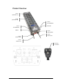
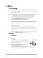
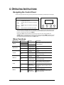
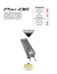
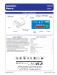
Snapshot Outdoor Use Sound Activated There are 2 different versions of this product. One version has a red LED display and the other has a blue LCD display. DMX Master/Slave Auto-ranging 100~240 VAC, 50/60 Hz Circuit Breaker User Serviceable Duty Cycle User Manual 5200 NW 108th Avenue, Sunrise, FL 33351 U.S.A. (800) 762-1084 – (954) 929-1115 FAX (954) 929-5560 www.chauvetlighting.com TABLE OF CONTENTS 1. BEFORE YOU BEGIN ....................................................................................................................................................... 3 WHAT IS INCLUDED................................................................................................................................................................................ 3 UNPACKING INSTRUCTIONS .................................................................................................................................................................... 3 AC POWER........................................................................................................................................................................................... 3 SAFETY INSTRUCTIONS .......................................................................................................................................................................... 3 2. INTRODUCTION ............................................................................................................................................................... 4 FEATURES ............................................................................................................................................................................................ 4 CONTROL FEATURES ................................................................................................................................................ 4 ADDITIONAL FEATURES ............................................................................................................................................ 4 PRODUCT OVERVIEW ............................................................................................................................................................................ 5 3. SETUP ............................................................................................................................................................................... 5 FIXTURE LINKING .................................................................................................................................................................................. 6 Power connection ......................................................................................................................................................... 6 MOUNTING ........................................................................................................................................................................................... 6 Orientation .................................................................................................................................................................... 6 Rigging .......................................................................................................................................................................... 6 4. OPERATING INSTRUCTIONS.......................................................................................................................................... 7 NAVIGATING THE CONTROL PANEL ......................................................................................................................................................... 7 MENU FUNCTIONS ................................................................................................................................................................................. 7 USER CONFIGURATIONS ........................................................................................................................................................................ 8 To set the DMX address ............................................................................................................................................... 8 5. APPENDIX......................................................................................................................................................................... 9 GENERAL MAINTENANCE ....................................................................................................................................................................... 9 General Troubleshooting .............................................................................................................................................. 9 RETURN PROCEDURE .......................................................................................................................................................................... 10 CLAIMS .............................................................................................................................................................................................. 10 TECHNICAL SPECIFICATIONS ................................................................................................................................................................ 11 CONTACT US ...................................................................................................................................................................................... 11 Pro-D6 User Manual 2 Rev. 4 1. BEFORE YOU BEGIN What is Included 1 x Warranty Card 1 x User Manual 1 x Pro-D6 Unpacking Instructions Immediately upon receiving a fixture, carefully unpack the carton, check the contents to ensure that all parts are present, and have been received in good condition. Notify the shipper immediately and retain packing material for inspection if any parts appear damaged from shipping or the carton itself shows signs of mishandling. Save the carton and all packing materials. In the event that a fixture must be returned, it is important that the fixture be returned in the original box and packing. AC Power To determine the power requirements for a particular fixture, see the label affixed to the back plate of the fixture or refer to the fixture’s specifications chart. A fixture’s listed current rating is its average current draw under normal conditions. All fixtures must be powered directly off a switched circuit and cannot be run off a rheostat (variable resistor) or dimmer circuit, even if the rheostat or dimmer channel is used solely for a 0% to 100% switch. Before applying power to a fixture, check that the source voltage matches the fixture’s requirement. Check the fixture or device carefully to make sure that if a voltage selection switch exists that it is set to the correct line voltage you will use. Warning! Notes! All fixtures must be connected to circuits with a suitable Earth Ground. Input voltage equals output voltage. Line A must be used when only one line is needed in order for the unit to function properly. Safety Instructions Please read these instructions carefully, which include important information about the installation, usage and maintenance of this product. • • • • • • • • • • Caution! Please keep this User Guide for future consultation. If you sell the unit to another user, be sure that they also receive this instruction booklet. This product is intended for indoor use only! To prevent risk of fire or shock, do not expose fixture to rain or moisture. Make sure there are no flammable materials close to the unit while operating. The unit must be installed in a location with adequate ventilation, at least 20in (50cm) from adjacent surfaces. Be sure that no ventilation slots are blocked. Always disconnect from power source before servicing or replacing lamp or fuse and be sure to replace with same lamp source. Secure fixture to fastening device using a safety chain. Never carry the fixture solely by the cables. Use its carrying handles. Maximum ambient temperature (Ta) is 104° F (40° C). Do not operate fixture at temperatures higher than this. In the event of a serious operating problem, stop using the unit immediately. Never try to repair the unit by yourself. Repairs carried out by unskilled people can lead to damage or malfunction. Please contact the nearest authorized technical assistance center. Make sure the power cord is never crimped or damaged. Never disconnect the power cord by pulling or tugging on the cord. There are no user-serviceable parts inside the unit. Do not open the housing or attempt any repairs yourself. In the unlikely event your unit may require service, please contact CHAUVET at: 954-929-1115. Pro-D6 User Manual 3 Rev. 4 2. INTRODUCTION Features CONTROL FEATURES • • • • 6-channel DMX-512 dimmer / relay pack Each channel can be set to any DMX address Each channel can be set as either dimmer or relay Variable electronic dimmer (0-100%) ADDITIONAL FEATURES • • • • • Dimmer curve selection for each channel: square, switch or linear Dual 20 A power lines (requires 2 separate circuits) Individual switch, circuit breaker and plug per line Accommodates different input voltages simultaneously 2 Edison plugs per channel Pro-D6 User Manual 4 Rev. 4 Product Overview Line A (Channels 1-3) Line B (Channels 4-6) Line B Circuit Breaker DMX Out Line A Circuit Breaker DMX In Line B Power Switch Line B Power Cord Line A Power Switch Line A Power Cord 20 A Plug Connection Pro-D6 User Manual 5 Rev. 4 3. SETUP Fixture Linking You will need a serial data link to run light shows of one or more fixtures using a DMX-512 controller, or to run synchronized shows on two or more fixtures set to a master/slave operating mode. The combined number of channels required by all the fixtures on a serial data link determines the number of fixtures the data link can support. Important: Fixtures on a serial data link must be daisy chained in one single line. To comply with the EIA-485 standard no more than 32 devices should be connected on one data link. Connecting more than 32 fixtures on one serial data link without the use of a DMX optically-isolated splitter may result in deterioration of the digital DMX signal. Maximum recommended serial data link distance: 500 meters (1640 ft.) Maximum recommended number of fixtures on a serial data link: 32 To link fixtures together you must obtain data cables. You can purchase CHAUVET® certified DMX cables directly from a dealer/distributor or construct your own cable. If you choose to create your own cable please use data-grade cables that can carry a high quality signal and are less prone to electromagnetic interference. Power connection The Pro-D6 has been designed to work on multiple input voltages (100-240VAV 50/60Hz) simultaneously, and comes fitted with 20 amp connectors for this purpose. For example, Line A can be plugged into 120V and Line B can be plugged into 230V. Any voltage between 100-240 volts may be used. The power for the Line A and the Line B circuits must share the same electrical phase. The unit will not operate properly if they are on different phases. Mounting Orientation This fixture may be mounted in any position provided there is adequate room for ventilation. Rigging It is important never to obstruct the fan or vents pathway. Mount the Hanging Clamp fixture using, a suitable “C” or “O” type clamp. Adjust the angle of the fixture by loosening both knobs and tilting the fixture. After finding the desired position, retighten both knobs. • • • When selecting installation location, take into consideration lamp replacement access and routine maintenance. Safety cables must always be used. Never mount in places where the fixture will be exposed to rain, high humidity, extreme temperature changes or restricted ventilation. Pro-D6 User Manual 6 Note! Clamp is sold separately. Rev. 4 4. OPERATING INSTRUCTIONS Navigating the Control Panel Access control panel functions using the four panel buttons located directly underneath the LCD Display. Button Function <MENU> Used to select and store the current menu or option within a menu <UP> Scrolls through menu options in ascending order <DOWN> Scrolls through menu options in descending order <ESC> Used to return to a previous menu option MENU UP DOWN ESC The Control Panel LCD Display shows the menu items you select from the menu map. When a menu function is selected, the display will show immediately the first available option for the selected menu function. To select a menu item, press <MENU>. Pressing the <ESC> button will allow access to the top of the menu map. Use the <UP> and <DOWN> buttons to navigate the menu map and menu options. Press the <MENU> button to access the menu function currently displayed, or to enable a menu option. To return to the previous option or menu without changing the value, press the <ESC> button. Menu Functions MAIN FUNCTION DMX fail SUB-FUNCTION Hold Prog1-12 Blackout Block DMX address Single ALL Preheat Single ALL Max level Single ALL SELECTION INSTRUCTION Speed time Value=00.2s-20.0s Start addr Value=[001-512] CH[01-06] Value=[001-512] ALL Manual Single Pro-D6 User Manual Select a DMX starting address [000-050%] Select a separate DMX address for each channel Select a preheat percentage for all channels CHAN[01-06] Select a preheat percentage for each Value=[000-050%] channel independently [000-100%] Select a maximum operation level for all channels CHAN[01-06] Select a maximum operation level for each Value=[000-100%] channel independently SWITCH-LINEAR Select operation mode for all channels: dimmer (0-100%) or relay (0/100%) Curve Single Select how the product will react if there is no DMX detected CHAN[01-06] SWITCH-LINEAR Select operation mode for each channel independently: dimmer (0-100%) or relay [000-100%] (0/100%) Manually manipulate the output of all channels simultaneously CHAN[01-06] Manually manipulate the output of each Value=[000-100%] channel independently 7 Rev. 4 User Configurations To set the DMX address 1) Select “DMX address” by pressing <Menu>, then the <Up/Down> buttons, until the display reads correctly. 2) Press <Menu> to reach the second step of the addressing menu. 3) Use the <Up/Down> buttons to select Block or Single mode. 4) Press the <Menu> button. 5) Use the <Up/Down> buttons to select the correct value. Once you are satisfied with your input, press <Menu>to confirm your selection. 6) Pressing the <Esc> button will allow you to back out of this menu. This is useful if you wish to select the option for setting each channel to a different dmx address. Pro-D6 User Manual 8 Rev. 4 5. APPENDIX General Maintenance To maintain optimum performance and minimize wear, fixtures should be cleaned frequently. Usage and environment are contributing factors in determining cleaning frequency. As a general rule, fixtures should be cleaned at least twice a month. Dust build up reduces light output performance and can cause overheating. This can lead to reduced lamp life and increased mechanical wear. Be sure to power off the fixture before conducting maintenance. Unplug the fixture from power. Use a vacuum or air compressor and a soft brush to remove dust collected on external vents and internal components. Clean all glass when the fixture is cold with a mild solution of glass cleaner or Isopropyl Alcohol and a soft lint free cotton cloth or lens tissue. Apply solution to the cloth or tissue and drag dirt and grime to the outside of the lens. Gently polish optical surfaces until they are free of haze and lint. The cleaning of internal and external optical lenses and/or mirrors must be carried out periodically to optimize light output. Cleaning frequency depends on the environment in which the fixture operates: damp, smoky or particularly dirty surrounding can cause greater accumulation of dirt on the unit’s optics. Clean with soft cloth using normal glass cleaning fluid. - Always dry the parts carefully. - Clean the external optics at least every 20 days. Clean the internal optics at least every 30/60 days. General Troubleshooting Applies to Symptom Solution(s) Lights Foggers & Snow Controllers Dimmers & Chaser Auto shut off Check fan thermal switch reset Breaker/Fuse keeps blowing Check total load placed on device Chase is too slow Check users manual for speed adjustment Device has no power Check for power on Mains. Check device’s fuse. (internal and/or external) Fixture is not responding Check DMX Dip switch settings for correct addressing Check DMX cables Check polarity switch settings Fixture is on but there is no movement to the audio Make sure you have the correct audio mode on the control switches. If audio provided via ¼” jack, make sure a live audio signal exists Adjust sound sensitivity knob Loss of signal Use only DMX cables Install terminator Note: Keep DMX cables separated from power cables or black lights. Relay will not work Check circuit breaker reset switch Check cable connections If you still have a problem after trying the above solutions, please contact CHAUVET Technical Support at the location on the next page. Pro-D6 User Manual 9 Rev. 4 Return Procedure Returned merchandise must be sent prepaid and in the original packing; call tags will not be issued. Package must be clearly labeled with a Return Merchandise Authorization Number (RMA #). Products returned without an RMA # will be refused. Call CHAUVET and request an RMA # before shipping the fixture. Be prepared to provide the model number, serial number and a brief description of the cause for the return. Be sure to properly pack fixture, any shipping damage resulting from inadequate packaging is the customer’s responsibility. As a suggestion, proper UPS packing or double-boxing is always a safe method to use. CHAUVET reserves the right to use its own discretion to repair or replace product(s). Note: If you are given an RMA #, please include the following information on a piece of paper inside the box: 1) 2) 3) 4) 5) Your name Your address Your phone number The RMA # A brief description of the symptoms Claims Damage incurred during shipping is the responsibility of the shipper; therefore, the damage must be reported to the carrier upon receipt of merchandise. It is the customer's responsibility to notify and submit claims with the shipper in the event that a fixture is damaged during shipping. Any other claim for items such as missing component/part, damage not related to shipping, and concealed damage, must be made within seven (7) days of receiving merchandise. Pro-D6 User Manual 10 Rev. 4 Technical Specifications WEIGHT & DIMENSIONS Length.............................................................................................................................. 18 in (457 mm) Width .............................................................................................................................. 5.8 in (147 mm) Height ............................................................................................................................... 3.8 in (97 mm) Weight .............................................................................................................................. 9.7 lbs (4.4 kg) POWER Auto-ranging (input voltage equals output voltage) ............................................... 100-240VAC 50/60Hz Maximum power output (per channel) ............................................................................................... 10A Circuit breaker (Line A)...................................................................................................................... 20A Circuit breaker (Line B)...................................................................................................................... 20A Maximum load ................................................................................................................................... 40A THERMAL Maximum ambient temperature ........................................................................................... 104°F (40°C) CONTROL & PROGRAMMING Data input ................................................................................................ locking 3-pin XLR male socket Data output ........................................................................................... locking 3-pin XLR female socket Data pin configuration .............................................................................. pin 1 shield, pin 2 (-), pin 3 (+) Protocols........................................................................................................................ DMX-512 USITT ORDERING INFORMATION Pro-D6 ......................................................................................................................................... PROD6 WARRANTY INFORMATION Warranty .............................................................................................................. 2-year limited warranty The power for the Line A and the Line B circuits must share the same electrical phase. The unit will not operate properly if they are on different phases. Contact Us World Wide General Information CHAUVET 5200 NW 108th Avenue Sunrise, FL 33351 voice: 954.929.1115 fax: 954.929.5560 toll free: 800.762.1084 Technical Support CHAUVET 5200 NW 108th Avenue Sunrise, FL 33351 voice: 954.929.1115 (Press 4) fax: 954.929.5560 (Attention: Service) World Wide Web www.chauvetlighting.com Pro-D6 User Manual 11 Rev. 4