1
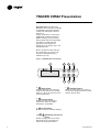
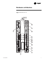
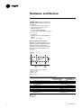
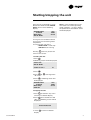
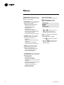
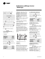
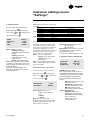
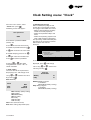
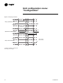
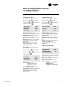
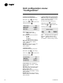
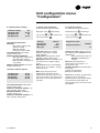
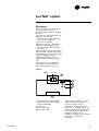
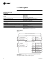
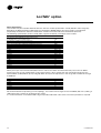
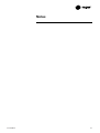
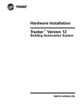
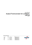
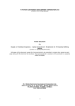
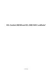
TRACER CH532 Chiller controller User guide CG-SVU01B-E4 General information Foreword Reception These Installation Operation and Maintenance instructions are given as a guide to good practice in the installation, start-up, operation and periodic maintenance by the user of TRACER CH532 chiller controller. They do not contain the full service procedures necessary for the continued successful operation of this equipment. The services of a qualified service technician should be employed, through the medium of a maintenance contract with a reputable service company. When the unit arrives on site, check it has not been damaged in any way during transport. If damage is observed, or even merely suspected, notify the carrier within 24 hours by registered letter. Notify the local Trane Sales office at the same time. The unit should be totally inspected within 3 days of delivery. If damage is observed, notify the last carrier by registered letter and notify the local sales office. Warranty Warranty is based on the general terms and conditions of the constructor. The warranty is void if the equipment is modified or repaired without the written approval of the constructor, if the operating limits are exceeded, or if the control system or the electrical wiring is modified. Damage due to misuse, lack of maintenance, or failure to comply with the manufacturer’s instructions, is not covered by the warranty obligation. If the user does not conform to the rules of “Maintenance”, it may entail cancellation of warranty and liabilities by the constructor. ©American Standard Inc. 2004 General information About this manual Cautions appear at appropriate places in this instruction manual. Your personal safety and the proper operation of this machine require that you follow them carefully. The constructor assumes no liability for installations or servicing performed by unqualified personnel. CG-SVU01B-E4 Contents Foreword 2 Warranty 2 Reception 2 General information 2 TRACER CH532 Presentation 4 Hardware architecture 5 Starting/stopping the unit 9 Menus 10 Display menu: “Data display” 11 Customer settings menu: “Settings” 12 Clock Setting menu: “Clock” 15 Unit configuration menu: “Configuration” 17 Alarms 22 Lon Talk option 25 Safety recommendations 32 Maintenance contract 32 Training 32 ® CG-SVU01B-E4 3 TRACER CH532 Presentation Important note: This document describes all the functions available on TRACER CH532 with software version 2.0 and explains how to program it. Certain parameters must only be modified by qualified personnel. Before changing any parameter, always check that the change does not affect the good and safe operation of the equipment. Operation must always stay in the catalogued limits. Built-in control terminal features: An LCD display (1), 4 lines x 20 characters with back lighting 6 buttons (2) to (7) Figure 1 - TRACER CH532 user interface 1 2 5 2. Alarm button: Used for displaying or manually resetting the alarms. The red LED lights up , when at least one alarm has been detected. 3 4 Prg Esc 6 7 7 Validation button Allows to move from line to line in the currently displayed screen and to confirm the set data. 3. Prg Program button: Allows the various operating parameters to be set (safety parameters, thresholds). 4. Esc Escape button: Allows the return to default display 5. 6. Downward and Upward arrows Allows management of currently displayed screen and setting of values of control parameters 4 CG-SVU01B-E4 Hardware architecture 10 11 Prg Esc 9 9 Figure 2 - TRACER CH532 inputs and outputs CG-SVU01B-E4 5 Hardware architecture Table 1 - TRACER CH532 General description Item 1 2 3 4 5 6 7 8 9 10 11 6 Description 24 V Power supply (G+,GO-) Yellow LED (Power on) Red LED (Alarm) Fuse (2A , 5x20) Universal Analog inputs: NTC,0/1V,0/10V,0/20mA, 4/20mA) Passive Analog Inputs (NTC,PT1000 , ON/OFF) Analog Outputs (0/10V) Digital Inputs (24Vac / Vdc) Digital Inputs (230Vac or 24Vac / Vdc) Relays digital output User interface Communication interface CG-SVU01B-E4 Hardware architecture Table 2 - Inputs and output summary list AI: Leaving water temperature sensor AI: Entering water temperature sensor AI: Ambient temperature sensor AI: Suction pressure circuit 1 - LP1 transducer AI: Suction pressure circuit 2 - LP2 transducer AI: Discharge pressure circuit 1 - HP1 transducer AI: Discharge pressure circuit 2 - HP2 transducer AI: External water setpoint reset (option) AI: Unused DI: Compressor C circuit 1 fault DI: Compressor C circuit 2 fault DI: Compressor A circuit 1 fault DI: Compressor B circuit 1 fault DI: Compressor A circuit 2 fault DI: Compressor B circuit 2 fault DI: High pressure Cut-out circuit 1 - HP1 switch DI: High pressure Cut-out circuit 2 - HP2 switch DI: Auxiliary set point On/Off DI: Fans circuit 1 fault DI: Fans circuit 2 fault DI: Circuit 1 On/Off (or Unit On/Off CH 532 medium) DI: Circuit 2 On/Off DI: Water flow control input DI: Water pump 1 fault DI: Water pump 2 fault DI: Faults external reset DI: Cooling/Heating mode switch DI: Unused DO: Compressor A circuit 1 output DO: Compressors B and C circuit 1 output DO: Compressor A circuit 2 output DO: Compressors B and C circuit 2 output DO: Fan 1 output Wye (Y) contactor - circuit 1 DO: Fan 1 output Delta (D) contactor - circuit 1 DO: Fan 2 output circuit 1 DO: Fan 3 output circuit 1 DO: Fan 1 output Wye (Y) contactor - circuit 2 DO: Fan 1 output Delta (D) contactor - circuit 2 DO: Fan 2 output circuit 2 DO: Fan 3 output circuit 2 DO: Water pump 1 DO: Water pump 2 DO: Antifreeze heater DO: Circuit 1 fault DO: Circuit 2 fault DO: Unit status or additional heating demand DO: Unused AO: Speed inverter - fan circuit 1 - HP1 output AO: Speed inverter - fan circuit 2 - HP2 output AO: 4-way valve circuit 1 AO: Unused AO: 4-way valve circuit 2 AO: Unused AO: Unused TRACER CH532 Medium Single circuit units B3: NTC B4: NTC B5: NTC B1: 4..20mA B2: 4..20mA B8: 0..10V-0..20mA B6, B7 ID1: 24Vac ID3: 24Vac ID4: 24Vac ID14H: 230Vac ID8: 24Vac ID5: 24Vac ID13H: 230Vac ID2: 24Vac ID9: 24Vac ID10: 24Vac ID6: 24Vac ID7: 24Vac ID11, ID12 NO7: NO-230Vac NO8: NO-230Vac NO3: NO4: NO5: NO6: NO-230Vac NO-230Vac NO-230Vac NO-230Vac NO1: NO-230Vac NO2: NO-230Vac NC12: NO-230Vac NO9: NO-230Vac NO10: NO-230Vac NO11, NO13 Y1: 0..10V Y3: 0..10V + CONVONOFF Y4 Y2 TRACER CH532 Large Dual circuit units B3: NTC B4: NTC B5: NTC l B1: 4..20mA B6: 4..20mA B2: 4..20mA B7: 4..20mA B8: 0..10V-0..20mA B9, B10 ID1: 24Vac ID17: 24Vac ID3: 24Vac ID4: 24Vac ID11: 24Vac ID12: 24Vac ID14H: 230Vac ID15H: 230Vac ID8: 24Vac ID5: 24Vac ID18: 24Vac ID13H: 230Vac ID16H: 230Vac ID2: 24Vac ID9: 24Vac ID10: 24Vac ID6: 24Vac ID7: 24Vac NO7: NO-230Vac NO8: NO-230Vac NO13: NO-230Vac NO14: NO-230Vac NO3: NO-230Vac NO4: NO-230Vac NO5: NO-230Vac NO6: NO-230Vac NO15: NO-230Vac NO16: NO-230Vac NO17: NO-230Vac NO18: NO-230Vac NO1: NO-230Vac NO2: NO-230Vac NC12: NO-230Vac NO9: NO-230Vac NO11: NO-230Vac NO10: NO-230Vac Y1: 0..10V Y2: 0..10V Y3: 0..10V + CONVONOFF Y4 Y5: 0..10V + CONVONOFF Y6 Y2 Legend: AI: Analog Input DI: Digital Input AO: Analog Output DO: Digital Output CONVONOFF: ON/OFF converter CG-SVU01B-E4 7 Hardware architecture TRACER CH532 offers customer the possibility to use inputs or outputs in order to: - use an external water setpoint reset using an analog input (refer to figure 3) - use an auxiliary setpoint - connect a remote on/off of the unit or a circuit - reset faults - connect a remote Cooling/Heating switch - return a circuit fault Note: External water setpoint Based on a external signal input, it will be possible to offset the active setpoint from 0°C to 20°C. This function can be used in conjunction with the automatic setpoint reset function. Water setpoint Figure 3 5 4 1 2 Ambient temperature 3 1. Leaving water temperature setpoint 2. Minimum value 3. Maximum value 4. Reset = 20°C 5. Active setpoint Table 3: Customer Inputs and output summary list AI DI DI DI DI DI DO DO DO External water setpoint reset (option) Auxiliary setpoint On/Off Circuit 1 On/Off (or Unit On/Off for single circuit units) Circuit 2 On/Off Faults external reset Cooling/Heating mode switch Circuit 1 fault Circuit 2 fault Unit status or additional heating demand TRACER CH532 Medium TRACER CH532 Large Single circuit units Dual circuit units B8: 0..10V-0..20mA ID8: 24Vac - - ID13H: 230Vac ID16H: 230Vac ID6: 24Vac ID7: 24Vac NO9: NO-230Vac NO11: NO-230Vac NO10: NO-230Vac Legend: AI: Analog Input DI: Digital Input DO: Digital Output 8 CG-SVU01B-E4 Starting/stopping the unit Once the unit is powered on (main disconnect switch closed) TRACER CH532 returns to the following display: TRACER CH532 01/05/04 Water Temp OFF BY KEYB. V2.0 00:00 20.0°C Note: In case of power failure unit will restart in the state (operating mode, setpoints…) it was in before the power failure and default screen will be displayed. Line 2 gives current date and time Line 3 gives current leaving water temperature Line 4 gives the unit status: OFF BY KEYB = Local stop UNIT ON = Unit running Esc Pressing from any screen will return to this screen. 1. Starting the unit: 1. Press 2. Following screen will be displayed: Status Unit OFF BY KEYB. Switch on unit ? N 3. Press 4. Press or “N” to “Y” to change from 5. Press . Following screen will be displayed: TRACER CH532 01/05/04 Water Temp UNIT ON V2.0 00:00 20.0°C 2. Stopping the unit Esc 1. Press to exit from any menu and return to default display. 2. Press for 3 seconds unit will stop, and following screen will be displayed: Unit Switched Off 3. Press display CG-SVU01B-E4 Esc to return to default 9 Menus TRACER CH532 allows the user to access 4 menus to display or adjust operation parameters: • “Data display” menu - This menu allows the user to visualize all operation parameters: - Water and air temperatures - Refrigerant pressures - Saturated refrigerant temperatures - Compressors status - Compressor running hours - Number of compressors starts - Unit operating mode - Compressors failures counters • “Settings” menu - This menu is password protected. It allows access to the settings of: - Setpoints - Offset of cooling and heating setpoints - Unit operation validation - Customer inputs and outputs Accessing the menus From any screen displayed, press Esc , TRACER CH532 will then display the following screen: Data Display Settings Clock Configuration 1. or allow the cursor to move from line to line thus selecting one of the 4 menus. Note: The selection is displayed in capital characters 2. Once one line is selected, press to validate the choice. Esc 3. Pressing will exit the menu selection mode and return to default display. • “Clock” menu - This menu is password protected. It allows access to the settings of: - Day of the week, hour, date - Daily or weekly program - Hourly zone program • “Configuration” menu - This menu is password protected. It allows to adjust or change: - Unit definition - Compressors timers - High pressure control - Dead band, antifreeze and heater setpoints - Type of sensors and transducers - Operation protections - Cooling mode limitations - Defrost parameters - Compressor alarms 10 CG-SVU01B-E4 Display menu: “Data display” From the menu screen, select “Data Display” then press Pressing or will allow navigation from screen 1 to 8 as shown hereafter: The menu is looped making it possible to scroll from the first item in the menu to the last item. Lvg Wat Temp Ret Wat Temp Amb Temp Active StP 08.0°C 12.0°C 28.0°C 07.0°C 1. Water and air temperatures Lvg Wat Temp = Leaving water temperature Ret Wat Temp = Entering water temperature Amb Temp = Ambient air temperature Active StP = Active water setpoint HP ckt1 HP ckt2 LP ckt1 LP ckt2 00.0 00.0 00.0 00.0 bar bar bar bar 2. Refrigerant pressures HP ckt1 = Condensing Pressure circuit 1 HP ckt2 = Condensing Pressure circuit 2 (dual circuit units only) LP ckt1 = Evaporating Pressure circuit 1 LP ckt2 = Evaporating Pressure circuit 2 (dual circuit units only) 3. Refrigerant saturated temperatures Sat Temp Sat Temp Sat Temp Sat Temp CDS1 CDS2 EVP1 EVP2 00.0°C 00.0°C 00.0°C 00.0°C Cmp A1 Cmp B1 C1 Cmp A2 Cmp B2 C2 000000 000000 000000 000000 Starts Starts Starts Starts Sat Temp CDS1 = Condensing temperature circuit 1 Sat Temp CDS2 = Condensing temperature circuit 2 (dual circuit units only) Sat Temp EVP1 = Evaporating temperature circuit 1 Sat Temp EVP2 = Evaporating temperature circuit 2 (dual circuit units only) Starts indicates the number of compressor starts since first start-up. Legend for screens 4,5 and 6: Cmp A1 = Compressor A/circuit 1 Cmp B1/C1 = Compressor B and C/circuit 1 Cmp A2 = Compressor A/circuit 2 (dual circuit units only) Cmp B2/C2 = Compressor B and C/circuit 2 (dual circuit units only) Mode = Running mode - Cooling = Cold water production - Heating = Hot water production (Reversible chillers only) Stp Local 07.0°C - Stp = Current setpoint - Local = Source of Setpoint Local = Cooling or heating setpoint defined locally Extern = Auxiliary setpoint or operating mode by external contact Auto = setpoint by the automatic reset or the daily/weekly program Remote = Setpoint by supervisor Cmp A1 Cmp B1 C1 Cmp A2 Cmp B2 C2 Off Off Off Off 4. Compressors status Possible Status: Off = Compressor stopped On = Compressor running Rec.On = Compressor will start after anti-short cycle Rec.Off = Compressor will stop after anti-short cycle 7. Operating mode Mode Stp Ckt1 Ckt2 Local Cooling 07.0°C Enable Enable Ckt1/Ckt 2 = Operational circuits - Enable = Circuit is operational - Disable = Circuit is not operational 8. Compressors failures counters Cmp A1 Cmp B1 C1 Cmp A2 Cmp B2 C2 000000 000000 000000 000000 Hrs Hrs Hrs Hrs 5. Compressors running time Hrs indicates the number of full hours compressor has been working since its first start. CG-SVU01B-E4 6. Number of compressors starts Nb Cpt Cpt Cpt of CMP faults A1:0 B1:0 C1:0 Cpt A 2:0 Cpt B 2:0 Cpt C 2:0 This menu indicates the number of compressors failure regardless of the history. 11 Customer settings menu: “Settings” From the menu screen, select Cooling Stp = Cold water setpoint (-12 to 20°C - factory setting: 7°C) Heating Stp = Hot water setpoint (20 to 60°C - factory setting: 45°C) Aux Wat Stp = Auxiliary setpoint (-12 to 60°C - factory setting: 10°C) Aux Wat = Auxiliary setpoint from external source: Enable = Auxiliary setpoint validated Disable = Auxiliary setpoint nonvalidated “Settings” then press . Following screen will appear: User password 0000 Enter password:”0000” (factory-set) Press . Automatic cooling and heating mode setpoints reset and cursor will move to first field of password. Pressing or will change the value from 0 to 9999. Keeping pressure on or will move the numbers fast. Press to confirm password. Pressing will allow navigation from screen 1 to 5 as shown hereafter: TRACER CH532 offers the possibility to offset cold and/or hot water setpoints according to ambient air temperature. The automatic setpoint reset program will allow you to change the water temperature setpoint (cooling and heating mode) with the ambient temperature. This function can be used in conjunction with the external setpoint reset function. Figure 4 2.1 Cooling mode setpoint reset To access one of the parameters displayed, press value using and change or . Confirm the value by pressing Cold water reset Start Point End Point Reset Delta N 20.0°C 30.0°C 10.0°C Cold Water Reset: Ambient temperature based cold water setpoint offset Y = Enabled N = Disabled (factory setting) Start Point: Starting point (-15 to 50°C - factory setting: 20°C) End Point: Ending point (-15 to 60°C - factory setting: 30°C) Reset Delta: Reset amplitude (-15 to 15°C - factory setting: 10°C) 3. Heating mode setpoint reset (Reversible chillers only) To access one of the parameters 1. Setpoints displayed, press 5 Cooling Stp Heating Stp Aux Wat Stp Aux Wat 07.0°C 45.0°C 10.0°C Disable displayed, press value using and change or . Confirm the value by pressing Cooling StP Heating StP Aux Wat StP Aux Wat 12 07.0°C 45.0°C 10.0°C Disable value using or . Confirm the value by pressing 2 To access one of the parameters 4 1 and change Ambient temperature 3 1. Leaving water temperature setpoint 2. Starting point 3. Ending point 4. Reset delta 5. Active set point Below the reset starting point, the water temperature setpoint will be the normal setting. Between the starting and ending point the setpoint will vary proportionally with the ambient temperature. After the ending point, the setpoint will stay at its maximum or minimum value. Hot water reset Start Point End Point Reset Delta N 20.0°C 30.0°C 10.0°C Hot Water Reset: Ambient temperature based hot water setpoint offset Y = Enabled N = Disabled (Factory setting) Start Point: Starting point (-15 to 50°C - factory setting: 20°C) End Point: Ending point (-15 to 60°C - factory setting: 30°C) Reset Delta: Reset amplitude (-15 to 15°C - factory setting: 10°C) CG-SVU01B-E4 Customer settings menu: “Settings” 4. Operating mode Comp seq: Compressor sequencing To access one of the parameters displayed, press value using and change or . Confirm the value by pressing Mode Comp seq Ckt1 Ckt2 Cooling Auto Enable Enable Mode: Operating mode Cooling: Cold water production (default factory setting) Heating: Hot water production (Reversible chillers only) Extern: (external control) Note: When switching from cooling to heating mode or from heating to cooling mode, unit will stop for 15 s before restarting. To allow chiller waterflow rate adjustment disable circuit 1 and 2, then start the unit. 1-2: fix order Single circuit Start order Stop order 2-1: fix order Single circuit Start order Stop order Rotation Single circuit Start order Stop order Auto (default factory setting) Dual circuit A1,B1 B1, A1 A1, A2, B1, B2 B2, B1, A2, A1 Dual circuit B1,A1 A1, B1 A2, A1, B2, B1 B1, B2, A1, A2 Dual circuit A1,B1 A1,B1 A1, A2, B1, B2 A1, A2, B1, B2 The Auto sequence intend to have equivalent numbers of starts and stops and an equivalent number of compressor working hours. The compressor start order will prioritize the compressors which have the least number of working hours. Ckt1/2: Circuit 1/2 operation Enable: circuit operational Disable: circuit nonoperational Note: It is possible to disable both circuit 1 and 2. Water pump will be kept in operation 6. Customer outputs configuration Alarm Out: State Out: Pump Timer: MR only Unit state 01 min 5. Customer Inputs and Outputs To access one of the parameters displayed, press value using and change or . Confirm the value by pressing Analog Input Ana. Input 0..10V Disable Analog Input: Signal type 0..10V (factory setting) 0..1V 0..20mA 4..20mA Note: the total amplitude corresponds to reset delta of +20°C between 0%(0V,OA or 4 mA) and 100% (10V,1V, or 20 mA) CG-SVU01B-E4 Ana. Input External setpoint reset Y = Enabled N = Disabled Pump Timer: Time between unit stop (by keyboard or external contact) and stop of the pump (1 to 10 min - factory setting = 1 min) Default I/O: (NO9 / NO11) This output will be used to give an information about the circuit status: A configuration parameter will allow to choose between the following three indications concerning this circuit: ALL: All alarms (manual and automatic reset) ALL But LA: All alarms but without Low Ambient alarm MR only: Manual reset alarms only (factory setting) Status output: (NO10) Add Heat: indicate an additionnal heat demand Unit State Send data telling that at least one compressor is ON (factory setting) 13 Customer settings menu: “Settings” 7. Remote Mode To access one of the parameters displayed, press value using and change or . Confirm the value by pressing Chiller control Mode: Local Remote Local: Setpoints are entered on the module. Orders sent from the BMS are not taken into account. Remote: Orders sent from the BMS are taken into account. 14 CG-SV01B-E4 Clock Setting menu: “Clock” From the menu screen, select “Clock” then press . Following screen will appear: User password 0000 Enter default password:”0000” (factory set) Press and cursor will move to first field of password. Pressing or will increment the value from 0 to 9999. Keeping pressure on or Press will move the numbers fast. to confirm password. 2. ON/OFF program type When enabled, this program will control the unit operation (On/Off). This program will allow the user to: - Make a choice between the daily and/or the weekly operation - Define the operational days and hours - Define the operating setpoints for each mode (cooling and heating) The operating mode selected by the operator or by the external control will be taken into account. Example: Time 00:00 02:00 04:00 06:00 08:00 10:00 12:00 14:00 16:00 18:00 20:00 22:00 Monday Tuesday Wednesday Thursday Friday Saturday Example Operation enable from Monday to Friday from 8:00 to 18:00 To access one of the parameters Pressing or will allow navigation from screen 1 to 3 as shown hereafter: displayed, press 1. Clock setting To access one of the 4 parameters displayed, press and change value value by pressing using or . Confirm the value by pressing Mon: Weekday Clock Hour Date Mon 00:00 00/00/00 value using and change or . Confirm the Program On/Off Unit Weekly Daily N N Weekly: Weekly program Y: Enabled N: Disabled (factory setting) Daily: Daily program Y: Enabled N: Disabled (factory setting) Mon: Monday (factory setting) Tue: Tuesday Wed: Wednesday Thu: Thursday Fri: Friday Sat: Saturday Sun: Sunday Hour: Time (hours/minutes) Date: Date setting (day/month/year) CG-SV01B-E4 15 Clock Setting menu: “Clock” 2.1 Weekly program To access one of the parameters To validate hourly zone program, press displayed, press and change value using and change or value using or . Confirm the value by . Confirm the pressing value pressing Program Hourly zone Program Weekly Start Stop Mon Fri Disable Start: Starting day Stop: Ending day Disable: No program Enable: Program used 2.2 Daily program To access one of the parameters 3.1 Defining Zones To access one of the parameters displayed, press displayed, press value using and change or . Confirm the value using Program Daily Zone #1 00:00 00:00 3. Hourly Zone The Daily/weekly program will allow you to define the cooling mode and heating mode setpoints. It will be possible to define within a day, four operating zones with different setpoint as follows: Example: Std setpoint . Confirm the Start Cooling Stp Heating Stp Start: Start time Stop: Stop time Time 07:00 08:00 09:00 10:00 11:00 12:00 13:00 14:00 15:00 16:00 17:00 18:00 or value by pressing value by pressing Start Stop and change Zone 1 00:00 07.0°C 45.0°C Start: Beginning Time Cooling StP: Cooling mode setpoint (-20 to 20°C - factory setting: 7°C) Heating StP: Heating mode setpoint - Reversible chillers only (20 to 60°C factory setting: 45°C) Press or to reach zones 2,3 and 4. Proceed the same way as above for programming parameters. Zone 2 Zone 3 Setpoint Zone 4 Std Stp Stp 1 Operating hours 8:00-18:00 Stp 2 Starting at 10:00 Starting at 11:00 Starting at 13:00 Stp 3 Starting at 16:00 Stp 4 Note: The automatic or external setpoint compensation or the external setpoint will change the standard setpoint only but will not affect the setpoints defined for the hourly zones 1, 2, 3 or 4. 16 CG-SV01B-E4 Unit configuration menu: “Configuration” From the menu screen, select “Configuration” then press Following screen will appear: . User password 0000 Figure 5 - Single pump operation Note: figures 5 to 8, Unit Off means that the unit is stopped by keyboard or by an external contact On Enter default password:”0000” (factory-set) Press and cursor will move to first field of password. Pressing or On Pump will increment the value from Off t 0 to 9999. Keeping pressure on or will move the numbers fast. Figure 6 - Dual pump operation Press to confirm password. Pressing or will allow navigation from screen 1 to 11 as shown hereafter: 1. Unit definition To access one of the 4 parameters displayed, press On Unit Off On Pump 1 Off and change On value using or . Confirm the Pump 2 Off value by pressing t Unit type: Refrg Fans/ckt Water pump Chiller R407C 3 Single Unit Type: Unit type Chiller: Cooling only Heat pump: Reversible chiller Refrg: Refrigerant R407C, R134a, R410A or R22 Fans/ckt: Number of fans per circuit: 1, 2, or 3 Note: Setting number of fans at 0, will stop all the fans, but will allow the compressors to run before being stopped by HP switch. Water Pump: Water pump type Single: Single pump control Dual: Dual pump control Note: Pump operation The water pumps can be single or dual. A timer is used to delay the pump shut down in normal operating conditions. The timer is reset at each unit start. CG-SV01B-E4 When twin pumps are used, a pump switch will occur at each start and also in case of fault on the pump in operation. Figure 7 - Single pump protection Pump protectioninput Pump protectionoutput Unit stopped (manual reset) 17 Unit configuration menu: “Configuration” Figure 8 - Dual pump protection Pump 1 Pump protection input Pump 2 Fault reset Pump 1 Message 46* Message 46* Operation Enable/Disable Pump 2 Message 47* Pump 1 Pump control outputs Unit stopped (manual reset) Pump 2 * refer to “alarms” section for meaning of message 18 CG-SV01B-E4 Unit configuration menu: “Configuration” 2. Compressors timers To access one of the parameters 4. Control dead bands To access one of the parameters displayed, press displayed, press value using and change or . Confirm the value by pressing ACC 1st Start ACC On-On Min On-On Min Off-Off value using and change or . Confirm the value by pressing 2 min 5 min 060 s 015 s ACC 1st Start: Short cycle compressor at first start (0 to 60 min - factory setting: 2min) ACC On-On: Short cycle between 2 starts of the same compressor (2 to 10 min - factory: 5 min) Min On-On: Minimum time to add compressor (5 to 240 s - factory setting: 60s) Min Off-Off: Minimum time to remove compressor (1 to 120 s factory setting 15s) Dead band Cmp 03.0°C Antifreeze Heater 02.0°C 03.0°C Dead band Cmp: Compressors regulation dead band around water temperature (0.4 to 8.0°C - factory setting: 3.0°C) AntiFreeze: Cold water temperature limit (-15 to 10°C - factory setting: 2°C) Heater: Evaporator heater setpoint according to ambient air temperature (0 to 10°C - factory setting: 3°C) 5. Winter Freeze Protection 3. HP Control To access one of the parameters displayed, press value using and change or . Confirm the CW High Limit Pmp Cycle OFF WinFreezeProtPmp Ctrl Pump Required 15°C 10 min Yes value pressing Fan control Fan Ctrl Stp Dead band Fan 1Speed 15.0 b 06.0 b Fan Control: Fan type: 1 speed: 1 Speed fan 2 speed: 2 Speed fan Invert: Inverter Fan Ctrl StP: Fan control setpoint (10 to 30 bar - factory setting: 15 bar) Dead band Fan: Fans regulation dead band (2 to 8 bar - factory setting: 5 bar) CG-SV01B-E4 Chilled water high limit: (15 to 25°C: factory setting 15°C) Water pump cycle OFF: (5 to 15 min: factory setting 10min) Winter Freeeze protection with pump: No ² Heater or Ethylene Glycol Required Yes ² Ctrl Pump Required 19 Unit configuration menu: “Configuration” 6. Sensors and transducers To access one of the parameters displayed, press value using and change or . Confirm the 8. Analog Output (for speed inverter) Note: This screen is displayed only if “Invert” has been selected in the HP control menu (refer to §3) To access one of the parameters displayed, press value by pressing value using Temp probe Press probe Min Press Max Press NTC 4..20mA 0.0bar 30.0bar Temp probe: Sensor type: NTC (factory setting) PT100 Press probe: Pressure transducer: 0..10V 0..1V 0..20mA 4..20mA (factory setting) Min Press: Pressure at 0V, 0mA or 4 mA (-1.0 to 0.0 bar - factory setting: 0.0 bar) Max Press: Pressure at 10V, 1V or 20 mA (16 to 50 bar - factory setting: 30bar) and change or . Confirm the value by pressing Analog output Low High OV 10V 08.0 bar 16.0 bar Low 0V: Minimum fan speed (0 to 10 bar - factory setting: 8 bar) High 10V: Maximum fan speed (11 to 40 bar - factory setting: 16 bar) 7. Operation limits To access one of the parameters displayed, press value using and change or . Confirm the value by pressing LP (Sat Temp) Timer LP HP Cool Stp HP Heat Stp -4°C 60 s 28.0 bar 28.0 bar LP (Sat Temp): Low evaporating pressure limit (-25 to 0°C - factory setting: -4°C) Timer LP: Low pressure fault timer after compressor start (0 to 300 s factory setting: 60s) HP Cool StP: High pressure limit in cooling mode (15 to 40 bar - factory setting: 28 bar) HP Heat StP: High pressure limit in heating mode (15 to 40 bar - factory setting: 28 bar) 20 CG-SV01B-E4 Unit configuration menu: “Configuration” 9. Operating limits (cooling) Low Amb Cooling Low Amb Limit CW High Limit CW High Limit On -10.0°C On 15.0°C 11. Defrost cycle termination To access one of the parameters 12. Compressor alarm To access one of the parameters displayed, press displayed, press value using and change or . Confirm the 10. Defrost demand setpoint Low Amb Heat StP Min Temp Defrost Max StP Max Temp -10.0°C 10.0°C 12.0°C 22.0°C Low ambient heating: -20 to 20°C, factory setting -10°C Setpoint at minimum ambient: 1 to 30°C, (factory setting 10°C) Maximum ambient: -20 to 20°C: (factory setting 12°C) Setpoint at maximum ambient: 1 to 30°C, (factory setting 22°C) CG-SV01B-E4 Term Stp Drying time Max Defrost Min cycle or . Confirm the value by pressing value by pressing Low ambient temperature limitation: On: (factory setting) Low ambiant limited Off: Low ambient temperature not limited Low ambient limit: -20 to 20°C: factory setting -10°C Chilled water high limitation: On: High water temperature limited (factory setting) Off: High water temperature not limited Chilled water high limit: 10 to 20 °C: Factory setting 15°C value using and change 20.0 bar 12 s 7 min 25 min Term StP: Defrost termination setpoint (10 to 30bar - factory setting: 20 bar) Drying time: Drying time (5 to 30 seconds - factory setting: 12s) Max Defrost: Maximum defrost time (5 to 30 minutes - factory setting: 7 min) Min cycle: Minimum time between defrost cycle (15 to 60min - factory setting: 25 min) Note: Dual circuits have two independent refrigerant circuits. Defrost cycle will only occur on the circuit that needs it. The other circuit will continue its normal operation if required. Compressor alarm 00000 h Default parameters? N Compressor alarm: Operating hours for a warning (0 to 999000 hours by 1000 hours) Setting compressor alarm at 000000 h will disable the function. Note: Total operating hours = compressor running hours + 3 x compressor starts Default parameters?: Set the default parameters Y: Reset all parameters N: Keep all parameters Note: When resetting, all parameters programmed on site will be definitively lost. Only factory default set parameters will be kept. Full configuration of the unit will have to be checked. 21 Alarms 1. Alarms display and Resetting A fault on a unit will be shown through the user interface or through 2 digital outputs, one for each refrigerant circuit. The alarms are divided into 3 categories: - Warning. Shows that something is wrong on the unit but unit can be kept in operation. A message is displayed on the user interface screen. These messages are not recorded in the history list. - Fault with automatic reset: when the cause of the fault disappears, the fault is cancelled and unit operation will return to normal. The messages displayed on the user interface screen disappear but are recorded in the history list of faults. The fault is relayed through the digital output if I/O parameter is set to show a circuit fault. - Fault with manual reset: when the cause of the fault disappears, a manual reset is required to restart the unit. The messages displayed on the user interface screen disappear and are recorded in the history list of faults. The fault is relayed through the digital output if I/O parameter is set to show a circuit fault. Should an alarm occur, lit in red. 2. Alarms history 200 events can be recorded by TRACER CH532. Each record will give the fault description, the reset type, the order and the day and time of occurrence. Maintaining for 5 seconds give will access to the last event recorded. Then using allows the user to view the complete history. (refer to table 5 for possible messages) will be Pressing once will display the alarm message (refer to table 4 for possible messages) When alarm message is displayed press to reset the default if necessary. 22 CG-SV01B-E4 Alarms Table 4 - Status, warnings and alarm messages No 1 2 3 4 5 6 7 8 9 10 11 12 13 14 15 16 17 18 19 20 21 22 23 Message No Alarm Ext. Ckt1 Stop Ext. Ckt2 Stop User Ckt1 Stop User Ckt2 Stop Remote Ckt1 Stop Remote Ckt2 Stop Clock Unit Stop Operator Stop Ckt1 Defrost Ckt2 Defrost Warning Comp.1 Maintenance Warning Comp.2 Maintenance Warning Comp.3 Maintenance Warning Comp.4 Maintenance Alarm Air Sensor Alarm Ckt 1 Fault Alarm Ckt 2 Fault Alarm Ckt1 HP Limit Alarm Ckt1 Limiting Alarm Ckt2 HP Limit Alarm Ckt2 Limiting Alarm Comp. A1 Fault Reset Type Manual Manual Manual Manual Auto Manual Manual Auto Auto Auto Auto Auto/Manual Unit status Unit On Circuit 1 Off Circuit 2 Off Circuit 1 Off Circuit 2 Off Circuit 1 Off Circuit 2 Off Unit Off Unit Off Unit On Unit On Unit On Unit On Unit On Unit On Unit Off Circuit 1 Off Circuit 2 Off Unit On Unit On Unit On Unit On CMP A1 Off 24 Alarm Comp. B1 Fault Auto/Manual CMP B1 Off 25 Alarm Comp. C1 Fault Auto/Manual CMP C1 Off 26 Alarm Comp. A2 Fault Auto/Manual CMP A2 Off 27 Alarm Comp. B2 Fault Auto/Manual CMP B2 Off 28 Alarm Comp. C2 Fault Auto/Manual CMP C2 Off 29 30 31 32 33 34 35 36 37 38 39 40 41 42 43 44 45 46 47 Alarm Ext. Setpoint Signal Alarm Fan Protection 1 Alarm Fan Protection 2 Alarm HP Ckt1 Fault Alarm HP Ckt2 Fault Alarm HP Sensor Ckt1 Alarm HP Sensor Ckt2 Alarm Low Ambient Alarm Low Water Temp Alarm LP Ckt1 Fault Alarm LP Ckt2 Fault Alarm LP Sensor Ckt1 Alarm LP Sensor Ckt2 Alarm Unit Fault Alarm Water Flow (**) Alarm Water In Sensor Alarm Water Out Sensor Alarm Water Pump1 Alarm Water Pump2 Auto Auto Auto Manual Manual Auto Auto Auto Manual Auto/Manual Auto/Manual Auto Auto Manual Auto Auto Auto Manual Manual Unit Off Unit On Unit On Circuit 1 Off Circuit 2 Off Circuit 1 Off Circuit 2 Off Unit Off Unit Off Circuit 1 Off Circuit 2 Off Circuit 1 Off Circuit 2 Off Unit Off Unit Off Unit On Unit Off Unit On Unit On Description See unit status on Main display Circuit 1 Off by Digital Input (Dual circuit units) Circuit 2 Off by Digital Input (Dual circuit units) Circuit 1 Disable by Settings (via keyboard) Circuit 2 Disable by Settings (via keyboard) Circuit 1 Disable by Supervision Circuit 2 Disable by Supervision Unit Off by Program (Hourly, Weekly) Unit Off by Operator (via keyboard) Circuit 1 under defrosting Circuit 2 under defrosting Compressor running hours above the threshold defined in unit configuration.Each compressor start is equal to 3 running hours. Defective Air sensor Simultaneous manual reset faults CMP A1 and (B1 or C1) Simultaneous manual reset faults CMP A2 and (B2 or C2) Compressor B1C1 Off for high HP ckt1 Compressor B1C1 Off for Hot water or low LP ckt1 Compressor B2C2 Off for high HP ckt2 Compressor B2C2 Off for Hot water or low LP ckt2 Manu if CMP A1 failure > 35 min or 6 failures within 3 hours 30 min Manu if CMP B1 failure > 35 min or 6 failures within 3 hours 30 min Manu if CMP C1 failure > 35 min or 6 failures within 3 hours 30 min Manu if CMP A2 failure > 35 min or 6 failures within 3 hours 30 min Manu if CMP B2 failure > 35 min or 6 failures within 3 hours 30 min Manu if CMP C2 failure > 35 min or 6 failures within 3 hours 30 min Defective device or bad device configuration Defective fan on the circuit 1 Defective fan on the circuit 2 High Pressure Cut-Out circuit 1 High Pressure Cut-Out circuit 2 Defective pressure sensor HP1 Defective pressure sensor HP2 Ambient temperature too low for unit operation LWT < antifreeze or INT (antifreeze-EWT)<=10°Cxsecond Suction pressure too low on circuit 1 Suction pressure too low on circuit 2 Defective pressure sensor LP1 Defective pressure sensor LP2 All the compressors are defectives No water flow. Reset by unit Off/On when pump Off Defective Return water sensor Defective Leaving water sensor Defective water pump 1 Defective water pump 2 (**) When the unit is shut down after a waterflow alarm for more than 1 minute, it is necessary to switch the unit Off and On again to reset the fault. The fault will automatically reset if the water pump is still running. CG-SV01B-E4 23 Alarms Table 5 - History events record No Message No History Air Sensor Reset Type Auto Auto Unit status Unit On Unit Off Water In Sensor Auto Unit On Water Out Sensor Auto Unit Off Lp Sensor Ckt1 Auto Circuit 1 Off Hp Sensor Ckt1 Auto Circuit 2 Off Lp Sensor Ckt2 Auto Circuit 1 Off Hp Sensor Ckt2 Auto Circuit 2 Off Fan Protection 1 Fan Protection 2 Lp Ckt1 fault Auto Auto Auto or Manual Unit On Unit On Circuit 1 Off Lp Ckt2 fault Auto or Manual Circuit 2 Off Low Water Temp Comp. A1 Fault Manual Auto or Manual Unit Off CMP A1 Off Comp. B1 Fault Auto or Manual CMP B1 Off Comp. C1 Fault Auto or Manual CMP C1 Off Comp. A2 Fault Auto or Manual CMP A2 Off Comp. B2 Fault Auto or Manual CMP B2 Off Comp. C2 Fault Auto or Manual CMP C2 Off Hp Ckt1 Fault Hp Ckt2 Fault Ckt1 Fault Ckt2 Fault Unit Fault Ext Setpoint Signal Manual Manual Manual Manual Manual Auto Circuit 1 Off Circuit 2 Off Circuit 1 Off Circuit 2 Off Unit Off Unit Off Low Ambient Water Pump 1 Water Pump 2 Water Flow Auto Manual Manual Auto Unit Off Unit On Unit On Unit Off Air temperature below the setpoint while unit On Fault on water pump #1 Fault on water pump #2 Loss of water flow for more than 4 sec when the system is On. Pump restarts by a manual unit Off and On Auto Auto Unit On Unit On Defrost on circuit 1 Defrost on circuit 2 Defrost Ckt1 Defrost Ckt2 24 Description No alarm was recorded Faulty sensor, out of range -30..+80°C (short circuit or open circuit) Faulty sensor, out of range -30..+80°C (short circuit or open circuit) Faulty sensor, out of range -30..+80°C (short circuit or open circuit) Faulty sensor, out of range 0..10V, 0..1V,0..20mA or 4..20mA following configuration Faulty sensor, out of range 0..10V, 0..1V,0..20mA or 4..20mA following configuration Faulty sensor, out of range 0..10V, 0..1V,0..20mA or 4..20mA following configuration Faulty sensor, out of range 0..10V, 0..1V,0..20mA or 4..20mA following configuration A fan on the circuit 1 is faulty A fan on the circuit 2 is faulty Lp circuit 2 is below the setpoint. Manual reset after 3 faults within 1 hour Lp circuit 1 is below the setpoint. Manual reset after 3 faults within 1 hour LWT < antifreeze or INT (antifreeze-EWT)<=10°Cxsecond Manual reset if CMP A1 failure > 35 min or 6 failures within 3 hours 30 min Manual reset if CMP B1 failure > 35 min or 6 failures within 3 hours 30 min Manual reset if CMP C1 failure > 35 min or 6 failures within 3 hours 30 min Manual reset if CMP A2 failure > 35 min or 6 failures within 3 hours 30 min Manual reset if CMP B2 failure > 35 min or 6 failures within 3 hours 30 min Manual reset if CMP C2 failure > 35 min or 6 failures within 3 hours 30 min High pressure switch Cut-Out circuit 1 High pressure switch Cut-Out circuit 2 Simultaneous faults compressor A1 and (B1 or C1) Simultaneous faults compressor A2 and (B2 or C2) Simultaneous faults on all the compressors Faulty sensor, out of range 0..10V, 0..1V,0..20mA or 4..20mA following configuration CG-SV01B-E4 LonTalk® option Description The Lon interface uses an Echelon FTT-10 transceiver, which is approved to be used on the TP/FT-10 channel. This channel is characterized by the following main features: • It consists of up to 60 nodes on a single network segment • Data rate : 78 125 kbps • Maximum distance : 1400 meters • Recommended topology : daisy chain with double end terminator (105 ohms) For futher details, refer to the official documentation LonWorks® FTT-10A free topology transeiver user’s guide and to the official LonWorks® guidelines LonMark® layer 1-6 interoperability guidelines version 3.0. These documents and additional information are available on the internet site www.lonmark.org Figure 9 GND A B 2 3 4 5 1 1. Connection to the Tracer CH532 2. Terminal block to the LonWorks® network (GND,A,B) 3. Service pin 4. Green status LED 5. Red service LED CG-SV01B-E4 To activate the service pin, simply short circuit the two pins for a moment using the tip of a screwdriver or similar tool. The service pin is available only in the node installation phase. When the pin is activated, the node sends a broadcast message in the LonWorks® containing the necessary information in order to be identified. 25 LonTalk® option LED meaning and function Green Status LED LED status LED is OFF continuously. Meaning/Function • Normal condition • Broken hardware • No power LED is ON. • Broken hardware · • During the activation of the service pin • The node is Applicationless LED blinks 1second then always OFF • When receiving a WINK command from the network (1) LED blinks ½ second ON then always OFF • Normal operation (usually after a reset) LED flashes once every second • The node card is not configured • The node card is in continuous reset (1) By sending a request, you can request the controller’s green status LED to blink (“wink”), a notification that the controller received the signal and is communicating. Red Service LED LED status LED is ON for 20 seconds when power is applied to the controller LED is OFF continuously Meaning/Function • The controller is in a reset phase • The controller is operating normally • Broken hardware • When power is applied to the controller • After a reset • The controller is not working properly • Broken hardware • Problems of connection with the CH532 module LED is ON during 2 seconds then always OFF LED is ON continuously Object details Figure 10 Chiller Controller 8040 Mandatory network variables nv1 nviChillerEnable snvt_switch nv3 nvoOnOff snvt_switch nv2 nviCoolSetpt snvt_temp_p nv4 nvoActiveSetpt snvt_temp_p Optional network variables nv7 nviMode Snvt_hvac_mode nv11 nvoLvgCHWTTemp snvt_temp_p nv8 nviHeatSetpt snvt_temp_p nv12 nvoEntCHWTTemp snvt_temp_p nv13 nvoEntCndWTemp snvt_temp_p nv15 nvoAlarmDescr snvt_str_asc nv16 nvoChillerStat snvt_chlr_status Note: BAS intergrators requiring .xif file need to contact their local sales representative. Other optional network variables are not supported. 26 CG-SV01B-E4 LonTalk® option Nv1 0=off 1=on nv2 range -12.2°C 48.8°C nv3 0=chiller off 1=chiller on nv4 range -40°C 93°C nv7 1=heat mode 3=cooling mode nv8 range 10°C 93°C nv11 range -40°C 118°C nv12 range -40°C 118°C nv13 range -40°C 118°C nv15 manual reset alarm auto reset alarm informational warning circuit 1 fans fault circuit 2 fans fault compressor A1 fault compressor B1 fault compressor C1 fault compressor A2 fault compressor B2 fault compressor C2 fault pump 1 fault pump 2 fault nv16 chlr_off=0, chlr_run=2 HVAC_HEAT=1, HVAC_COOL=3 Chiller state 0=No alarm, 1=In alarm Run _enable 0=Chiller not allowed to start, 1=Chiller can start Local 0=Values can be changed remotely, 1=Values cannot be changed remotely Limited (Not used) CHW_flow 0=No water flow, 1=Water flow detected CONDW_flow (Not used) All other bits unused Configuration properties nc73 ChillerEnable (m) nc52 inSendTime (m) nc4 MaxSendTime (m) nc7 CoolSetpt (m) nc74 Mode (o) nc78 HeatSetpt (o) nc48 Heartbeat (o) (m) = mandatory (o) = optional CG-SV01B-E4 27 LonTalk® option Cable characteristics Level 4 cable may be used with TP/FT-10 channels. The level 4 cable specification used by Echelon and as originally defined by the National Electrical Manufacturers Association (NEMA) differs from the Category 4 specification proposed by the Electronic Industries Association / Telecommunication Industries Association (EIA / TIA). The following specifications can be used by cable suppliers to identify a compliant Level 4 cable. Specifications apply to shield or unshielded 22AWG (0.65mm2) cable D-C resistance (ohms/1000 feet at 20°C) maximum for a single copper conductor regardless of whether it is solid or stranded and is or is not metal coated D-C resistance unbalance (percent) maximum Mutual capacitance of a pair (pF/foot) maximum Pair to ground capacitance unbalance (pF/1000 feet) maximum Characteristic impedance (ohms) 772 kHz 1.0 MHz 4.0 MHz 8.0 MHz 10.0 MHz 16.0 MHz 20.0 MHz Attenuation (dB/1000 feet at 20°C) maximum 772 kHz 1.0 MHz 4.0 MHz 8.0 MHz 10.0 MHz 16.0 MHz 20.0 MHz 18.0 5 17 1000 102+/- 15% 100 +/- 15% 100 +/- 15% 100 +/- 15% 100 +/- 15% 100 +/- 15% 100 +/- 15% 4.5 5.5 11 15 17 22 24 Worst pair to pair near end crosstalk (dB) minimum. Values are shown for information only. The minimum NEXT coupling loss for any pair combination at room temperature is to be greater than the value determined using the formula NEXT (F MHz)>NEXT (0.772)-15log10(F MHz / 0.772) for all frequencies in the range of 0.772 MHz for a length of 1000 feet. 772 kHz 1.0 MHz 4.0 MHz 8.0 MHz 10.0 MHz 16.0 MHz 20.0 MHz 58 56 47 42 41 38 36 For the TP/FT-10 channel operating in a bus topology , the maximum bus length of level 4 22AWG (0.65 mm2) cabling is 1400 meters with a maximum stub length of 3 meters. It is recommended to use shielded cable if high amplitude modulation noise exist or transient protection is required. 28 CG-SV01B-E4 Notes CG-SV01B-E4 29 Notes 30 CG-SV01B-E4 Notes CG-SV01B-E4 31 Safety recommendations Maintenance contract Training To avoid accidents and damage, the following recommendations should be observed during maintenance and service visits: 1. The maximum allowable pressures for system leak testing on low and high pressure side are given in the chapter “Installation”. Always provide a pressure regulator. 2. Disconnect the main supply before any servicing on the unit. 3. Service work on the refrigeration system and the electrical system should be carried out only by qualified and experienced personnel. It is strongly recommended that you sign a maintenance contract with your local Service Agency. This contract provides regular maintenance of your installation by a specialist in our equipment. Regular maintenance ensures that any malfunction is detected and corrected in good time and minimizes the possibility that serious damage will occur. Finally, regular maintenance ensures the maximum operating life of your equipment. We would remind you that failure to respect these installation and maintenance instructions may result in immediate cancellation of the warranty. The equipment described in this manual is the result of many years of research and continuous development. To assist you in obtaining the best use of it and maintaining it in perfect operating condition over a long period of time, the manufacturer has at your disposal a refrigeration and air conditioning service school. The principal aim of this is to give operators and technicians a better knowledge of the equipment they are using, or that is under their charge. Emphasis is particularly given to the importance of periodic checks on the unit operating parameters as well as on preventive maintenance, which reduces the cost of owning the unit by avoiding serious and costly breakdown. The manufacturer has a policy of continuous product improvement, and reserves the right to alter any details of the products at any time without notice. This publication is a general guide to install, use and properly maintain our products. The information given may be different from the specification for a particular country or for a specific order. In this event, please refer to your nearest office. For additional information, contact: Distributor/Installer stamp www.trane.com For more information contactyour local district office or e-mail us at comfort@trane.com Literature Order Number CG-SVU01B-E4 Date 0304 Supersedes CG-SVU01A-E4-0902 Stocking Location Europe Trane has a policy of continuous product and product data improvement and reserves the right to change design and specifications without notice. Only qualified technicians should perform the installation and servicing of equipment referred to in this publication. American Standard Europe BVBA Registered Office: 1789 Chaussée de Wavre, 1160 Brussels - Belgium