1
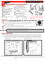
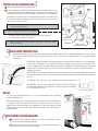
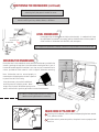
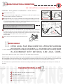
BUILT-IN DISHWASHER
INSTALLATION INSTRUCTIONS
PLEASE READ COMPLETE INSTRUCTIONS BEFORE YOU BEGIN
LEAVE INSTALLATION INSTRUCTIONS AND
USER'S GUIDE WITH OWNER
ALL ELECTRIC WIRING AND PLUMBING MUST BE DONE
IN ACCORDANCE WITH NATIONAL AND LOCAL CODES.
PRINTED IN USA
© 1999 - Maytag Corporation
6 915126 B
rt Here
Sta
TOOLS NECESSARY FOR INSTALLATION
SUPPORT ACCESSORIES:
CUTTING KNIFE
RATCHET
3/16", 1/4", 5/16" SOCKETS
PHILLIPS SCREWDRIVER
STANDARD SCREWDRIVER
WIRE CUTTERS
CRESCENT WRENCH
ADJUSTABLE PLIERS
LEVEL
3/4" UL Approved Strain Relief (provided)
2 Appropriate Sized Wire Nuts
3/8" Male (N.P.T.) Compression Elbow
or Flare Elbow
Thread Sealing Tape or Pipe Thread Compound
Appropriate Sized Hose Clamp
2 Wood Mounting Screws (provided)
Water Hook-Up Kits Available:
(Water line, water valve fitting, Teflon™ tape, tee valve fitting)
5’ Braided Stainless Steel
5’ Copper
(Not included: Tools required for preparing
the cabinet opening).
Part #19950153
Part #19950152
Available through an authorized Maytag Parts Retailer
NOTE: Make sure you have everything
necessary for proper installation before
going to step 2.
UNCRATING
Remove access and toe panels before beginning installation.
Remove bolts from the crate base brackets, using 5/16" socket with ratchet. Remove crate base and
discard base and packaging. Until dishwasher is permanently installed, beware of opening the
door as the unit may tip for ward.
Open the door and remove accessor y package from silver ware basket.
Remove any extra packing material from outside and inside the dishwasher. This would include plug in water valve inlet.
Loosen front leg bolts with a crescent wrench. Adjust rear leg bolts in same manner.
TIP: Pre-measure cabinet height to that of the dishwasher. Dishwasher should be 1/4" lower than that of the cabinet opening.
It's easier to adjust the dishwasher outside the cabinet than inside.
CABINET PREPARATION
Prepare cabinet as needed. Electrical and water facilities should enter cabinet opening on the floor, or through the back or side walls,
as shown in the shaded portion of the drawing. Preferred drain outlet is shown in the upper portion of the cabinet in drawing below.
Care should be taken to route plumbing away from the motor and blower (if equipped). DO NOT make connections until dishwasher
is in position. Care should be taken to make sure cabinet holes for power cord and hoses have no sharp edges.
3”
Preferred
Drain Area
dishwasher dimensions
Keep back free
of drain, water &
electrical supply
34-35”
cabinet opening
33 3/4" (Min.)
35 1/4" (Max.)
Preferred
Drain Area
24”
5”
24
”
Door Panel
Access Panel
7”
8”
3” 5”
CUSTOM PANELS AVAILABLE
22
Toe Panel
3/4
"
23 7/8
Dishwashers come with pre-installed panels. Custom panels are available: stainless steel and
trims kits for wood panels. See your authorized selling dealer for a complete list of products
available.
WATER VALVE PREPARATION
Remove shipping plug from water inlet valve.
Water
Valve
Install a 90° elbow (3/8" N.P.T) fitting into the water valve using Teflon™ tape
or pipe thread compound. The opposite end of the fitting should fit in-coming hot
water supply line. Position the end of the elbow towards the rear of the dishwasher.
IMPORTANT: DO NOT connect a sweat type fitting directly to the water valve
as the required heat will damage the water inlet valve. Do not solder within 6"
(15.2 cm) from the water valve.
Tip: You may want to gently lay the dishwasher on it’s back to aid installation
of the water valve fitting.
Tip: Teflon™ tape wraps clockwise onto threads.
CAUTION: With the door open, dishwasher may tip forward if
it is not secure in position to cabinet.
3/8"
Male NPT
Water
Su
(National Pipe Thread)
Tip: Drain hose may have a small amount of water left from factory quality
assurance testing.
90° Elbow
pply
3/8" or 1/2"
Compression Fitting
DRAIN HOSE PREPARATION
Dishwasher drain must have a 32" (81.2) loop. Drain hose may be clipped to either side of the dishwasher (see diagram A). It is preferred
that the drain hose be routed high enough to provide the 32" loop. If a loop cannot be put in the installation, an air gap (not included)
may be used.
IMPORTANT: Routing of the drain hose is most important to insure satisfactory operation. It is not recommended
to extend drain line beyond 7' (2.1 m). However, should this be necessary, it must always be attached to a line
of larger inside diameter. An accessory drain hose extension kit (#904204) is available through your authorized
dealer. DO NOT route drain hose across the top of the tub, all bends must be gradual to prevent kinking or
collapsing of the hose.
Diagram A
Drain Hose Clip
IMPORTANT: Drain hose may change position even after installation. To insure proper operation, secure hose
to either side of cabinet wall, or to tub with hose clip (provided) to assure a 32" loop. Make certain there are
no kinks.
IMPORTANT: Do not attach the drain hose to any connection smaller than 1/2" I.D.
(Side view of dishwasher)
IMPORTANT: Never cut the corrugated portion of drain hose. All connections
must be made to rubber portions of drain hose. If cutting of drain hose is required,
do not cut past the 5/8" line.
DRAIN
A 5/8" (1.6 cm) I.D. (Inside Diameter) x 7 ft. (2.1 m) corrugated drain hose is positioned
on side of dishwasher tub.
Drain hose connection can be located on either side of compartment. Elevate drain hose
to a height of at least 32" (81 cm) above the floor. If drain connection is to be made
below the floor, hose should be left in the looped position. It may be necessary to extend
drain hose for connection. DO NOT reduce the drain hose to less than 1/2" (1.3 cm) I.D.
(Inside Diameter).
POSITIONING THE DISHWASHER
With the door latched, position dishwasher in front of cabinet opening. Insert
drain hose through the opening provided.
Guide dishwasher into the cabinet, pulling drain hose through opening as you
proceed. Make sure drain hose is not kinked.
Multi-flex Drain Hose
POSITIONING THE DISHWASHER (continued)
Tip: Check to be sure there is no interference with water line
and wiring. Verify that power is turned off at source.
Tip: When installing dishwasher near a corner, allow enough room for the door to open
without interferring with any cabinets, drawers, or hardware.
LEVEL DISHWASHER
Leveling legs align the dishwasher vertically and horizontally. A combination of these
two adjustments are necessary to properly position the dishwasher and insure proper fit
of door and latch. Dishwasher must be LEVEL, solid, and square.
Door Spring
Adjustment Screw
3/16 Hex Head
Tip: Disregard the squareness of cabinets, cabinet trim may be used to correct situation later.
Leveling Leg
8
SECURING THE DISHWASHER
Make pilot holes in the underside of counter and drive wood screws, provided in the
accessor y package, through holes in the dishwasher mounting bracket. If part of
the bracket extends beyond the cabinet front, they may be trimmed with wire
cutters, provided sufficient material is lef t to support dishwasher mounting.
Note: Dishwasher must be secured properly to
countertop to avoid tipping when the door is open and
to prevent the tub from twisting.
It may be necessar y to provide an additional
anchoring source for mounting screws. Wood
strips across the top of dishwasher opening can be
used for solid surface or granite type counters to secure the dishwasher.
Tip: Refer to countertop manufacturer for complete
details on securing dishwasher to countertop.
9
DRAIN HOSE ATTACHMENT
If draining into the disposer, check to make sure disposal plug has been removed.
If not, remove as shown.
With dishwasher in permanent position, clamp drain hose to a properly sized
drain line.
MAKING THE ELECTRICAL CONNECTIONS
SEE THE ELECTRICAL REQUIREMENTS SECTION
CAUTION: Verif y power to dishwasher is off at source.
Remove terminal box cover.
In order to secure the power supply cable, a UL listed strain relief must be used to secure
the power supply to the back of terminal box.
Strip approximately 3/8" (.09 cm) of insulation from incoming power supply wires. Connect
these wires to wires from dishwasher wire harness located in the terminal box. Connect
wires using the appropriate size wire nuts, twisting and tightening securely over the wire
connections. Connect white to white and black to black.
Tip: To check for secure wire nut connection, gently tug on wire nut. If
wire nut comes off, repeat step 3.
Terminal Box
Black to Black
White
to White
Attach external ground wire from behind washer of green grounding screw. If an external
groundwire is used, insert the wire through the cable clamp and attach behind washer of
the green grounding screw. Attach the other end of external ground wire to a suitable
external ground. If a question arises, refer to your local
electrical codes.
Ground Screw
Secure the strain relief and replace the terminal box cover.
Strain Relief
11
WATER HOOKUP
CHECK LOCAL PLUMBING CODES FOR APPROVED PLUMBING
PROCEDURES AND ACCESSORIES.ALL PLUMBING SHOULD BE DONE
IN ACCORDANCE WITH NATIONAL AND LOCAL CODES.
Connect water supply line to water valve. Minimum 3/8" O.D. copper tubing or equivalent.
SHUTOFF VALVE: Install a hand shutoff valve in the water supply line in an accessible location, such as under the sink. The shutoff is optional,
but recommended and may be required by local codes. Connections are preferable located toward the left side of dishwasher. Care should be taken
to route plumbing away from motor and blower (if equipped). DO NOT make these connections until the dishwasher is in position.
Care should be taken to protect dishwasher and water lines leading to dishwasher from freezing. Damage from freezing is not covered by the
warranty.
FINALIZING THE INSTALLATION
Turn water supply on and check connections for leaks.
Turn power supply on.
Re-install Acess and Toe panels removed in step 2.
Run dishwasher through Rinse and Hold or equivalent cycle.
Check drain hose connection for leak.
CAUTION: Disconnect electrical power before you start!
ALL ELECTRICAL WIRING AND GROUNDING
SHOULD BE DONE IN ACCORDANCE WITH
NATIONAL AND LOCAL CODES.
CAUTION: To prevent accidental contact with electrical connections,
built-in dishwasher models must not be connected to a power source
unless the dishwasher is completely enclosed, with front panels
in place. If the back or either side of the dishwasher is exposed, a
custom-made panel must be used to complete this enclosure.
This dishwasher is designed for
operation on an adequately
wired individual 120 VAC,
60 Hz approved electrical
circuit. Use required fuse (15
amp) or comparable circuit
breaker. Two wire with ground
ser vice to the dishwasher
is recommended for connection
at the terminal box and for
grounding.
GROUNDING INSTRUCTIONS
CAUTION: To prevent the possibility of electrical shock, this dishwasher, as other electrical
appliances, must be adequately grounded. It is the responsibility of the installer at the point of
installation, taking into consideration local conditions and requirements.
This appliance must be connected to a grounded metal, permanent wiring system; or an equipment-grounding conductor
must be run with the circuit conductors and connected to the equipment-grounding terminal or lead on the appliance.
CAUTION: Disconnect electrical power to dishwasher before you start!
CHECK LOCAL PLUMBING CODES FOR APPROVED PLUMBING
PROCEDURES AND ACCESSORIES. ALL PLUMBING SHOULD BE DONE IN
ACCORDANCE WITH NATIONAL AND LOCAL CODES.
DOOR SPRING ADJUSTMENT
Dishwaser Side View
The door has two main springs, one located on each hinge. There are two slots on each hinge that allow
for door adjustment with the access panel removed.
ADJUSTMENT
SCREW
To change door spring tension, use a 1/4" hex-nut driver to either loosen or tighten a single screw located
on each door spring adjustment bracket. The spring adjustment brackets are located on either side of the
dishwasher frame. These brackets stretch the springs by sliding forward and back along the dishwasher
frame.
To increase spring tension: (If door falls too fast) Tighten each screw by turning clockwise.
To decrease spring tension: (If door falls too slowly) Loosen each screw by turning counterclockwise.
For heavy wood panels, an auxiliar y booster spring kit is available.