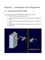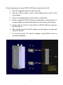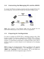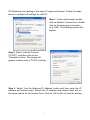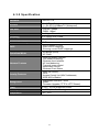
1
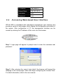
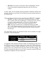
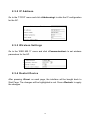
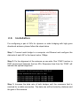
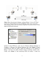
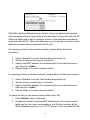
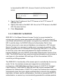
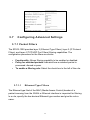
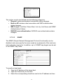
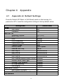
User’s Manual
Wireless LAN Outdoor AP/Bridge
Model No.: SP915-1000
World Wide Web: www.micronet.com.tw ; www.micronet.info
Table of Contents
Chapter 1 Introduction................................................................................... 1
1.1 Package Contents .......................................................................................... 1
1.2 Key Features ................................................................................................. 1
1.3 LED Indicator ............................................................................................... 2
Chapter 2 Installation and Configuration ....................................................... 3
2.1 Mounting the SP915-1000 ............................................................................ 3
2.2 Connecting the Managing PC and the SP915............................................... 5
2.3 Preparing for Configuration.......................................................................... 5
2.4 Accessing Web-based User Interface ........................................................... 7
2.5 Quick Setup via Web-Based UI.................................................................... 8
2.5.1 Operational Mode..............................................................................................8
2.5.2 IP Address ........................................................................................................10
2.5.3 Wireless Settings.............................................................................................10
2.5.4 Restart Device .................................................................................................10
2.6 Installation................................................................................................... 11
2.7 Setting up Client Computers....................................................................... 13
2.7.1 Configuring SP915-1000 Related Settings .................................................13
Chapter 3 Web-Based Management........................................................... 14
3.1 Overview..................................................................................................... 14
3.2 Menu Structure............................................................................................ 14
3.2.1 Save, Save & Restart, and Cancel ...............................................................15
3.2.2 Home and Refresh ..........................................................................................16
3.3 Status Menu ................................................................................................ 17
3.3.1 Wireless Clients ...............................................................................................17
3.3.2 DHCP Mappings..............................................................................................17
3.3.3 System Log ......................................................................................................18
3.3.4 Link Monitor......................................................................................................18
3.4 General Operation....................................................................................... 19
3.4.1 Operational Mode............................................................................................19
3.4.2 Changing Password........................................................................................20
3.4.3 Managing Firmware ........................................................................................20
3.5 TCP/IP Related Settings ............................................................................. 24
3.5.1 Addressing........................................................................................................24
3.5.2 Static DHCP Mappings...................................................................................24
3.6 IEEE 802.11 Menu...................................................................................... 25
3.6.1 Communication................................................................................................25
3.6.2 Security .............................................................................................................28
3.6.3 IEEE 802.1x/RADIUS .....................................................................................33
3.7 Configuring Advanced Settings.................................................................. 35
3.7.1 Packet Filters ...................................................................................................35
3.7.2 Management ....................................................................................................37
Chapter 4 Appendix..................................................................................... 40
4.1 Appendix A: Default Settings..................................................................... 40
4.2 Appendix B: Troubleshooting .................................................................... 41
4.2.1 Wireless Settings Problems...........................................................................41
4.2.2 TCP/IP Settings Problems .............................................................................42
4.3 Appendix C: Additional Information.......................................................... 44
4.3.1 Distances and Data Rates .............................................................................44
4.3.2 Specification .....................................................................................................45
Chapter 1 Introduction
Micronet proudly introduces SP915-1000, high power outdoor Access Point. It
is compliant with IEEE802.11b providing speed of up to 11Mbps. The AP
includes a Web-Based User Interface for easy management of your wireless
network. Security is intact with WEP, WPA and 802.1x for preventing
unauthorized access in wireless environment. SP915-1000 combining with
high power antenna (SP920MA-12) is ideal for distant inter-building
connection.
1.1
Package Contents
Prior to the installation of the device, please verify the following items are in
the package:
y
y
y
y
y
y
y
y
1.2
y
SP915-1000 Wireless LAN Outdoor AP/Bridge
Quick Installation Guide
Manual CD
1.2M 10/100Base-T/TX Ethernet Cable
25M Waterproof 10/100Base-T/TX Ethernet Cable
Wall-Mounting Kit
AC Power Cord
Power Injector
Key Features
Operational modes
¾ AP/Bridge provides both Access Point and Static LAN-to-LAN
Bridging functionality. The static LAN-to-LAN bridging function is
supported through Wireless Distribution System (WDS)
1
y
y
y
y
y
y
y
y
y
y
y
y
y
1.3
¾ AP Client is for Dynamic LAN-to-LAN Bridging. The AP Client
automatically establishes bridge links with APs from any vendors.
Enabling/disabling SSID broadcasts.
MAC-address-based access control.
Antenna alignment assistance.
Link health monitoring.
Wireless client isolation.
AP load balancing.
Transmit power control.
Association control can be configured to deny association requests
when it has served too many wireless clients or traffic load is too
heavy (AP/Bridge)
DHCP Server/Client including static DHCP mappings.
Provides Layer 2, Layer 3, and Layer 4 filtering capabilities.
System Log: local log and remote log by SNMP.
Supplying power to an AP over an Ethernet cable using PoE.
Restarts hardware when firmware failure is detected.
LED Indicator
There are several LED indicators inside the housing of the SP915-1000. They
are defined as follows:
y
y
y
y
ALV: Alive. Blinks when the AP is working normally.
RF: SP915-1000 interfaces activity
LAN: Ethernet LAN interface activity
PWR: Power
2
Chapter 2 Installation and Configuration
2.1
Mounting the SP915-1000
Follow steps below to mount SP915-1000 with a wall-mount kit #1.
1. Put the M6*90 screw into wall mount #1.
2. Fix the wall mount #1 to the bottom of SP915-1000 by using M4*80
screw.
3. Fix the SP915-1000 to the pole with the wall mount #1 using M6*90
screw.
4. Use M6 screw set, including spring washer and nuts, to finish the
installation.
3
Follow steps below to mount SP915-1000 with a wall-mount kit #2.
1. Stick the supplied sticker for wall mount #2.
2. Use the 7.00mm driller to drill a 25mm-deep hole at each of the
cross marks.
3. Plug in a supplied plastic conical anchor in each hole.
4. Screw a supplied ST3.9*20 screw in each plastic conical anchor for
a proper depth so that the wireless AP can be hung on the screws.
5. Fix two wall mounts #1 to the bottom of SP915-1000 by using two
M4*80 screws.
6. After fix wall mount #1 and #2, please see the diagram to align wall
mount #1 and #2.
7. Fix the wall mount #1 and #2 together using M4*80 screw to
complete installation.
4
2.2
Connecting the Managing PC and the SP915
To connect the Ethernet managing computer and the managed AP for firsttime configuration, users have two choices as illustrated in diagram below.
(Note: One connector of the Ethernet cable must be plugged into the
LAN/CONFIG Ethernet jack of the SP915-1000 for configuration.)
2.3
Preparing for Configuration
For users to configure the SP915-1000, a managing computer with a Web
browser is needed. For first-time configuration of an SP915-1000, an Ethernet
network interface card (NIC) should have been installed in the managing
computer. For maintenance-configuration of a deployed SP915-1000, either a
wireless computer or a wired computer can be employed as the managing
computer.
(Note: If users are using the browser, Opera, to configure an AP, click the
menu item <File>, click <Preferences...>, click <File types>, and <edit> the
<MIME> type, <text/html>, to add a file extension “.sht” so that Opera can
work properly with the Web management pages of the AP.)
5
PC/Notebook must belong in the same IP range and subnet. Follow the steps
below to configure IP settings for LAN PC.
Step 1. In the control panel, double
click on Network Connections. Double
click on the local area connection
(e.g. LAN). The following screen will
appear.
Step 2. Select ‘Internet Protocol
(TCP/IP)’, and then click on the
‘Properties’ button. The screen will
appear to allow entry of TCP/IP settings.
Step 3. Select ‘Use the following IP Address’ button and then enter the IP
address and subnet mask. Ensure the IP address and subnet mask are on
the same subnet as the Access Point. Click on ‘OK’ button to save the setting.
6
2.4
IP Address
192.168.0.1
Subnet Mask
255.255.255.0
Username
root
Password
root
Accessing Web-based User Interface
SP915-1000 is embedded with web-based management user interface and
provides a series of web pages, which display the configuration and status of
the system. After configuration of IP, the management interface can be
access by entering the IP address of the router into the browser.
Step 1. Login page will appear to prompt users to enter the username and
password.
Step 2. After entering the correct login detail, the browser will forward the
webpage to the setup page. Users can begin configuring the Access Point.
For detail information, refer to the user manual.
7
2.5
Quick Setup via Web-Based UI
Follow the following steps for quick setup of your wireless AP. Click <Save>
at the bottom of each configuration interface to save changes.
2.5.1 Operational Mode
Go to the ‘General’ menu and click <Operational Mode> to select a mode for
the AP.
The AP supports 2 operational modes:
y AP/Bridge: This mode provides both Access Point and Static LAN-toLAN Bridging functionality. The static LAN-to-LAN bridging function is
supported through Wireless Distribution System (WDS).
8
y
AP Client: This mode is for Dynamic LAN-to-LAN Bridging. The AP
Client automatically establishes bridge links with APs from any
vendors.
In either mode, the AP forwards packets between its Ethernet interface and
wireless interface for wired hosts on the Ethernet side and wireless host(s) on
the wireless side.
There are 2 types of wireless links as specified by the IEEE 802.11 standard.
y STA-AP: This type of wireless link is established between an IEEE
802.11 Station (STA) and an IEEE 802.11 Access Point (AP). An STA
is usually a client computer (PC or PDA) with a WLAN network
interface card (NIC). The AP Client mode is actually an STA.
y WDS: This type of wireless link is established between two IEEE
802.11 APs. Wireless packets transmitted along the WDS link comply
with the IEEE 802.11 WDS (Wireless Distribution System) format at
the link layer.
The relationships among the operational modes and the wireless link types
are shown in the following table:
AP/Bridge
AP Client
AP/Bridge
WDS
STA-AP
AP Client
STA-AP
To establish a static bridge link based on WDS, the AP/bridges at both end of
the WDS link must be manually configured with each other’s MAC addresses.
To establish a dynamic bridge link between an AP and an AP Client, both
devices have to be configured with the same SSID and WEP settings. The
AP Client automatically scans for any AP that is using the matched SSID and
establishes a bridge link with the scanned AP.
9
2.5.2 IP Address
Go to the ‘TCP/IP’ menu and click <Addressing> to alter the IP configuration
for the AP.
2.5.3 Wireless Settings
Go to the ‘IEEE 802.11’ menu and click <Communication> to set wireless
parameters for the AP.
2.5.4 Restart Device
After pressing <Save> on each page, the interface will be bought back to
Start Page. The changes will be highlighted in red. Press <Restart> to apply
the changes.
10
2.6
Installation
For configuring a pair of APs for dynamic or static bridging with high grain
directional antenna, please follow the steps below.
Step 1. Connect each bridge to a computer via Ethernet and configure the
data rate of each AP to the lowest value, 1Mbps.
Step 2. Fix the alignment of the antenna on one side. Run ‘PING’ function in
DOS environment between the two APs. Response time from the ‘PING’ will
indicate the optimal alignment.
Step 3. Increase the data rate of both bridges until the maximum limit is
reached for a stable connection. The data rate will be limited by distance and
the gain of the antenna.
11
(Note: When doing dynamic bridging, configure Bridge 1 to be in AP Client
mode and configure Bridge 2 to be in AP/Bridge mode. If users are doing
static bridging, make use of the Antenna Alignment Assistance feature to help
align the directional antennas.)
Instead of using PING.exe, users can run Wireless Network Manager on
Computer 1, and go to the Antenna Alignment tab. Click <Start> to begin
monitoring the WDS link quality. Adjust the alignment of the antenna of
Bridge 1 until the Link quality indicator shows a relatively maximal value.
Finally, click <Stop> to stop monitoring WDS link quality. If users are
12
installing dynamic bridging, use the Link Monitor feature on the AP Client side
to help align the directional antennas.
2.7
Setting up Client Computers
The TCP/IP and IEEE 802.11b-related settings of wireless client computers
must match those of the AP.
2.7.1 Configuring SP915-1000 Related Settings
Before the TCP/IP networking system of a wireless client computer can
communicate with other hosts, the underlying wireless link must be
established between this wireless computer and an AP.
To establish wireless link to the AP:
y Launch the configuration/monitoring utility provided by the vendor of
the installed WLAN NIC.
y Use the utility to make appropriate Operating Mode, SSID and WEP
settings.
y A wireless client computer must be in infrastructure mode, so that it
can associate with an AP.
y The SSID of the wireless client computer and the SSID of the AP
must be identical. Or, in case the SSID broadcasts capability of the
AP is enabled (by default), the SSID of the wireless client computer
could be set to “any”.
y Both the wireless client computer and the AP must have the same
WEP settings for them to communicate with each other.
13
Chapter 3 Web-Based Management
The following chapter will outline the web-based user interface used for
configuring SP915-1000.
3.1
Overview
Once, the login details are correctly entered, the web browser will proceed to
the following page containing overview of AP’s settings.
3.2
Menu Structure
The left side of the start page contains a menu for users to carry out
commands. Here is a brief description of the hyperlinks on the menu.
y Home: For returning back to the start page.
y Status: Status information.
¾ Wireless Clients: The status of the wireless clients currently
associated with the AP.
14
y
y
y
y
¾ DHCP Mappings: Current IP-MAC Address mappings of the builtin DHCP server.
¾ System Log: System events log.
¾ Link Monitor: When the AP is in AP Client mode, this page
shows the signal strength and link quality of the wireless link to its
associated access point.
General: General tools.
¾ Password: For gaining rights to change the settings of the AP.
¾ Firmware Tools: For upgrading the firmware of the AP, backing
up and restoring configuration, and configuration reset settings of
the AP.
TCP/IP: TCP/IP related settings.
¾ Addressing: IP address settings for the AP to work with TCP/IP.
¾ DHCP Server: Settings for the DHCP (Dynamic Host
Configuration Protocol) server on the AP.
IEEE 802.11: IEEE 802.11b-related settings.
¾ Communication: Basic settings for the IEEE 802.11b interface of
the AP to work properly with wireless clients.
¾ Security: Security settings for authenticating wireless users and
encrypting wireless data.
¾ IEEE 802.1x/RADIUS: IEEE 802.1x Port-Based Network Access
Control and RADIUS (Remote Authentication Dial-In User Service)
settings for better wireless security.
Advanced: Advanced settings of the AP.
¾ Packet Filters: Ethernet Type Filters, IP Protocol Filters, and
TCP/UDP Port Filters settings.
¾ Management: UPnP, System Log, and SNMP settings.
3.2.1 Save, Save & Restart, and Cancel
At the bottom of each page contains the following buttons: <Save>, <Save &
Restart>, and <Cancel>. Clicking <Save> stores the settings changes to the
memory of the AP and brings users back to the start page. Clicking <Save &
Restart> stores the settings changes to the memory of the AP and restarts
15
the AP immediately for the settings changes to take effect. Clicking <Cancel>
discards any settings changes and brings users back to the start page.
If users click <Save>, the start page will reflect the changed settings and
followed by two buttons: <Restart> and <Cancel>. In addition, changes are
highlighted in red. Clicking Cancel discards all the changes. Clicking Restart
restarts the AP for the settings changes to take effect.
3.2.2 Home and Refresh
At the bottom of each status page that shows read-only information, there are
two buttons: <Home> and <Refresh>. Clicking <Home> brings user back to
the start page. Clicking <Refresh> updates the status information.
16
3.3
Status Menu
3.3.1 Wireless Clients
On this page, the status information of each associated client, including its
MAC address, IP address, user name (if the client has been IEEE 802.1x
authenticated), number of bytes it has send, number of bytes it has received,
and the time of its last activity, are shown.
3.3.2 DHCP Mappings
On this page, all the current static or dynamic DHCP mappings are shown. A
DHCP mapping is a correspondence relationship between an IP address
assigned by the DHCP server and a computer or device that obtains the IP
address. A computer or device that acts as a DHCP client is identified by its
MAC address.
A static mapping indicates that the DHCP client always obtains the specified
IP address from the DHCP server. You can set static DHCP mappings in the
Static DHCP Mappings section of the DHCP Server configuration page. A
17
dynamic mapping indicates that the DHCP server chooses an IP address
from the IP address pool specified by the First allocatable IP address and
Allocatable IP address count settings on the DHCP Server configuration page.
3.3.3 System Log
System events are recorded in the memory of the AP. The logged information
is useful for troubleshooting purposes. The system events are divided into
several categories, and users can select which categories of events to log.
3.3.4 Link Monitor
When the SP915 is in AP Client mode, users can use the Link Monitor status
page to monitor the link quality and signal strength sensed by its RF module.
Larger values mean better wireless connectivity to its associated Access
Point. This feature is especially useful for aligning a pair of directional
antennas for bridging applications.
(Note: Values update every 20 seconds.)
18
3.4
General Operation
3.4.1 Operational Mode
The AP supports 2 operational modes:
y AP/Bridge: This mode provides both Access Point and Static LAN-toLAN Bridging functionality. The static LAN-to-LAN bridging function is
supported through Wireless Distribution System (WDS).
y AP Client: This mode is for Dynamic LAN-to-LAN Bridging. The AP
Client automatically establishes bridge links with APs from any
vendors.
In either mode, the AP forwards packets between its Ethernet interface and
wireless interface for wired hosts on the Ethernet side and wireless host(s) on
the wireless side.
There are 2 types of wireless links as specified by the IEEE 802.11 standard.
y STA-AP: This type of wireless link is established between an IEEE
802.11 Station (STA) and an IEEE 802.11 Access Point (AP). An STA
is usually a client computer (PC or PDA) with a WLAN network
interface card (NIC). The AP Client mode is actually an STA.
y WDS: This type of wireless link is established between two IEEE
802.11 APs. Wireless packets transmitted along the WDS link comply
with the IEEE 802.11 WDS (Wireless Distribution System) format at
the link layer.
The relationships among the operational modes and the wireless link types
are shown in the following table:
19
AP/Bridge
AP Client
AP/Bridge
WDS
STA-AP
AP Client
STA-AP
To establish a static bridge link based on WDS, the AP/bridges at both end of
the WDS link must be manually configured with each other’s MAC addresses.
To establish a dynamic bridge link between an AP and an AP Client, both
devices have to be configured with the same SSID and WEP settings. The
AP Client automatically scans for any AP that is using the matched SSID and
establishes a bridge link with the scanned AP.
(Note: Although it’s more convenient to use dynamic bridging, it has a
limitation. The AP Client only can forward TCP/IP packets between its
wireless interface and Ethernet interface and other type of traffic (such as IPX
and AppleTalk) is not forwarded.)
3.4.2 Changing Password
On this page, users can change the user name and password for the right to
modify the configuration of the bridge. The new password must be typed
twice for confirmation.
3.4.3 Managing Firmware
Firmware management operations for the SP915 include firmware upgrade,
configuration backup, configuration restore, and configuration reset. Firmware
upgrade, configuration backup, and configuration restore can be achieved via
HTTP or TFTP. The HTTP-based way is suggested because it’s more user-
20
friendly. However, due to different behavior of different Web browser types
and versions, HTTP-based firmware management operations may not work
properly with some Web browsers. If users cannot successfully perform
HTTP-based firmware management operations with the Web browser, try the
TFTP-based method.
Upgrade Firmware via HTTP
y Click <Browse> and then select a correct firmware .bin file. The
firmware file path will be shown in the Firmware file name text box.
y Click <Upgrade> to begin the upgrade process.
Backing up and Restoring Configuration Settings via HTTP
y Click <Back Up>.
y Users will be prompted to open or save the configuration file. Click
<Save>.
y The configuration file is named by the AP’s MAC address. For
example, if the AP’s MAC address is 00-01-02-33-44-55, the
configuration backup file should be “000102334455.hex”. Don’t
change the configuration file name in the Save As dialog box. Select a
folder in which the configuration file is to be stored, then click <Save>.
To Restore Configuration via HTTP
y Click <Browse> and then select a correct configuration .hex file.
Make sure the file name is the AP’s MAC address. The firmware file
path will be shown in the Firmware file name text box.
y Click <Restore> to upload the configuration file to the AP.
21
Upgrading Firmware via TFTP
When use TFTP as the firmware management protocol, users can configure
settings for the AP’s TFTP client to communicate with a TFTP server. If the
TFTP client does not get a response from the TFTP server within a period
specified by the Timeout setting, it will resend the previous request. The Max
number of retries setting specifies the maximal number of resend before the
TFTP client stops communicating with the TFTP server.
y
y
y
y
y
y
y
y
Get a computer that will be used as a TFTP server and as a
managing computer to trigger the upgrade process.
Connect the computer and one of the LAN Ethernet switch port with a
normal Ethernet cable.
Configure IP address of the computer so that the AP and the
computer are in the same IP subnet.
On the computer, run the TFTP Server utility. And specify the folder in
which the firmware files reside.
On the computer, run a Web browser and click the General, Firmware
Tools hyperlink.
Choose TFTP as the Firmware management protocol.
Specify the IP address of the computer, which acts as a TFTP server.
If users don’t know the IP address of the computer, open a Command
Prompt, and type IpConfig, then press the <Enter> key.
Trigger the firmware upgrade process by clicking Upgrade.
Backing up Settings by TFTP
y Get a computer that will be used as a TFTP server and as a
managing computer to trigger the backup process.
y Connect the computer and one of the LAN Ethernet switch port with a
normal Ethernet cable.
y Configure the IP address of the computer so that the computer and
the AP are in the same IP subnet.
22
y
y
y
y
y
On the computer, run the TFTP Server utility. Select the Accept write
requests check box, and specify the folder to which the configuration
settings of the AP will be saved.
On the computer, run a Web browser and click the <General>,
<Firmware Tools> hyperlink.
Choose TFTP as the Firmware management protocol.
Within the Configuration Backup/Restore section, specify the IP
address of the computer, which acts as a TFTP server. If users don’t
know the IP address of the computer, open a Command Prompt, and
type IpConfig, then press the <Enter> key.
Trigger the backup process by clicking <Back Up>. The AP’s
configuration settings will be saved as “AaBbCcDdEeFf.hex” by the
TFTP server, where “AaBbCcDdEeFf” is the AP’s MAC address. For
example, if the AP’s MAC address is 00-01-02-33-44-55, the
configuration backup file will be “000102334455.hex”.
To Restore Configuration via TFTP
y Get a computer that will be used as a TFTP server and as a
managing computer to trigger the restoring process.
y Connect the computer and one of the LAN Ethernet switch port with a
normal Ethernet cable.
y Configure the IP address of the computer so that the computer and
the AP are in the same IP subnet.
y On the computer, run the TFTP Server utility. Specify the folder in
which the configuration backup file resides. A configuration backup file
is named by the AP’s MAC address. For example, if the AP’s MAC
address is 00-01-02-33-44-55, the configuration backup file should be
“000102334455.hex”.
y On the computer, run a Web browser and click the <General>,
<Firmware Tools> hyperlink.
y Choose TFTP as the Firmware management protocol.
y Within the Configuration Backup/Restore section, specify the IP
address of the computer, which acts as a TFTP server. If users don’t
know the IP address of the computer, open a Command Prompt, and
type IpConfig, then press the <Enter> key.
23
y
Trigger the restoring process by clicking <Restore>. The AP will then
download the configuration backup file from the TFTP server.
Resetting Configuration to Factory Defaults
Clicking the <Reset> button resets the device configuration to factory defaults.
3.5
TCP/IP Related Settings
3.5.1 Addressing
The IP address of the AP can be manually set (Set Manually) or automatically
assigned by a DHCP server on the LAN (Obtain from a DHCP Server). If
users are manually setting the IP address, Subnet mask, and Default
gateway settings, set them appropriately, so that they comply with your LAN
environment. In addition, users can specify the Host name and Domain (DNS
suffix) of the AP.
3.5.2 Static DHCP Mappings
IP addresses of servers are often static so that clients could always locate the
servers by the static IP addresses. By Static DHCP Mappings, users can
ensure that a host will get the same IP address when it requests one from the
DHCP server. Therefore, instead of configuring the IP address of an intranet
24
server manually, you can configure the server to obtain an IP address by
DHCP and it is always assigned the same IP address.
y
y
3.6
Specify the MAC address of the DHCP client and the IP address to be
assigned. Then, give a description for this mapping.
Select the corresponding Enabled check box.
IEEE 802.11 Menu
3.6.1 Communication
3.6.1.1
Basic
Basic communication settings include AP functionality, Regulatory domain,
Channel number, Network name (SSID), Data rate, and Transmit power.
y
For specific needs such as configuring the AP as a wireless LAN-toLAN bridge, the AP functionality can be disabled, so that no wireless
25
y
y
y
y
client can associate with the AP. The number of available RF
channels depends on local regulations.
Therefore users have to choose an appropriate regulatory domain to
comply with local regulations.
The SSID of a wireless client computer and the SSID of the AP must
be identical for them to communicate with each other.
If there is RF interference, users may want to reduce the Data rate for
more reliable wireless transmission. In most cases, leave the setting
to ‘Auto’.
The transmit power of the RF module of the AP can be adjusted so
that the RF coverage of the AP can be changed.
3.6.1.2
Link Integrity
When the Ethernet LAN interface is detected to be disconnected from the
wired network, all currently associated wireless clients are disassociated by
the AP and no wireless client can associate with the AP. The detection
mechanism is based on ‘Ping’, the IP address specified in Reference host.
3.6.1.3
Association Control
If the number of currently associated wireless clients exceeds the value
specified in the ‘Max number of clients setting’, no more wireless client can
associate with the AP. If traffic load of the AP exceeds the load specified in
the ‘Block clients if traffic load exceeds setting’, no more wireless client can
associate with the AP.
26
3.6.1.4
AP Load Balancing
Several APs can form a load-balancing group if they are set with the same
‘Group ID’. The load-balancing policy can be by ‘Number of Users’ or by
‘Traffic Load’.
If the ‘Number-of-Users’ policy is selected, a new wireless user can only
associate with an AP that has the smallest number of associated wireless
users in the group. On the other hand, if the ‘Traffic-load Policy’ is selected, a
new wireless user can only associate with an AP that has the less traffic load
in the group.
3.6.1.5
Wireless Distribution System
Traditionally, access points are connected by Ethernet. By Wireless
Distribution System (WDS), APs can communicate with one another
wirelessly. For example, in the below diagram, AP 2 acts as an access point
for the notebook computers and it forwards packets sent from the notebook
computers to AP 1 through WDS. Then, AP 1 forwards the packets to the
Ethernet LAN. Packets destined for the notebook computers follow a reverse
path from the Ethernet LAN through the APs to the notebook computers. In
this way, AP 2 plays a role of “AP repeater”.
27
By WDS, two or more LAN segments can be connected wirelessly. As
illustrated in the below diagram, a pair of wireless LAN-to-LAN bridges is
used to connect two LAN segments. Since the AP is WDS-enabled, it can be
used as a wireless bridge.
y
y
Specify the MAC address of the AP at the other end of the WDS link.
Select the corresponding Enabled check box.
(Note: An AP can have up to 6 WDS links to other APs or wireless bridges.)
3.6.2 Security
Security settings include SSID broadcasts, Wireless client isolation, Security
mode, IEEE 802.11 Authentication algorithm, WEP keys, MAC-AddressBased Access Control.
3.6.2.1
Basic Security Setting
For security reasons, it’s highly recommended that the security mode be set
to options other than Open System. When the security mode is set to Open
System, no authentication and data encryption will be performed. Additionally,
you can disable the SSID broadcasts functionality so that a wireless client
computer with an “any” SSID cannot associate with the AP.
28
When the Wireless client isolation setting is set to ‘This AP Only’, wireless
clients of this AP cannot see each other, and wireless-to-wireless traffic is
blocked. When the setting is set to ‘All APs in This Subnet’, traffic among
wireless users of different APs in the same IP subnet is blocked. This feature
is useful for WLANs deployed in public places. In this way, hackers have no
chance to attack other wireless users in a hotspot.
When the Wireless client isolation setting is set to ‘This AP Only’, wireless
clients (STAs) of this AP cannot see each other, and wireless-to-wireless
traffic between the STAs is blocked. When the setting is set to ‘All APs in This
Subnet’, traffic among wireless users of different APs in the same IP subnet is
blocked. The behaviors are illustrated in the following figures.
STA 1
STA 3
STA 2
AP 1
AP 2
WCI:
This AP Only
WCI:
This AP Only
Switch
Wireless Link
Ethernet Link
Behavior of the “This AP Only” wireless client isolation option.
29
STA 1
STA 3
STA 2
AP 1
AP 2
WCI:
All APs in This
Subnet
WCI:
All APs in This
Subnet
Switch
Wireless Link
Ethernet Link
Behavior of the “All APs on This Subnet” wireless client isolation option.
As illustrated in the first figure when AP 1 and AP 2 are using the “This AP
Only” option, wireless traffic between STA 1 and STA 2 is blocked by AP 1.
While wireless traffic between STA 2 and STA 3, which are associated with
different APs, is still allowed. If the “All APs in This Subnet” option is used as
shown in second figure, AP 1 and AP 2 communicates with each other via an
inter-AP protocol to share their STA association information to block wireless
traffic among all the STAs.
There are up to 7 security modes depending on AP model variations:
y Open System: No authentication, no data encryption.
y Static WEP: WEP (Wired Equivalent Privacy) keys must be manually
configured.
y Static TKIP (WPA-PSK): Only TKIP (Temporal Key Integrity Protocol)
mechanism of WPA (Wi-Fi Protected Access) is enabled. In this mode,
users have to specify the Pre-shared key, which will be used by the
TKIP engine as a master key to generate keys that actually encrypt
outgoing
y IEEE 802.1x EAP without Encryption (EAP-MD5): The IEEE 802.1x
functionality is enabled and the user-name/password-based EAPMD5 authentication is used. No data encryption.
30
y
y
y
IEEE 802.1x EAP with Static WEP (EAP-MD5): The IEEE 802.1x
functionality is enabled and the user-name/password-based EAPMD5 authentication is used. Data encryption is achieved by static
WEP.
IEEE 802.1x EAP with Dynamic WEP (EAP-TLS, EAP-TTLS,
PEAP): The IEEE 802.1x functionality is enabled and dynamic WEP
key distribution authentication (EAP-TLS, EAP-TTLS, or PEAP) is
used. Data encryption is achieved by dynamic WEP.
IEEE 802.1x EAP with Dynamic TKIP (WPA): This is a full WPA
mode, in which both the TKIP and IEEE 802.1x dynamic key
exchange mechanisms are enabled. The AP is highly secured in this
mode.
In the above security modes, a back-end RADIUS (Remote Authentication
Dial-In User Service) server is needed if IEEE 802.1x functionality is enabled.
According to the IEEE 802.11 standard, WEP can be used for authentication
and data encryption. Normally, Shared Key authentication is used if WEP
data encryption is enabled. In rare cases, Open System authentication may
be used when WEP data encryption is enabled. The Authentication algorithm
setting is provided for better compatibility with wireless clients with various
WLAN network adapters. There are three options available, including Open
System, Shared Key, and Auto.
When WEP is enabled by a security mode, the Key length can be specified to
be 64 Bits or 128 Bits. The Selected key setting specifies the key to be used
as a send-key for encrypting traffic from the AP side to the wireless client side.
All 4 WEP keys are used as receive-keys to decrypt traffic from the wireless
client side to the AP side.
3.6.2.2
MAC-Address-Based Access Control
With MAC-Address-Based Access Control, users can specify the wireless
client computers that are permitted or not permitted to associate with the AP.
When the table type is set to inclusive, entries in the table are permitted to
associate with the AP. When the table type is set to exclusive, entries in the
table are not permitted to associate with the AP.
31
With MAC-Address-Based Access Control, users can specify the wireless
client computers that are permitted or not permitted to associate with the AP.
When the table type is set to inclusive, entries in the table are permitted to
associate with the AP. When the table type is set to exclusive, entries in the
table are not permitted to associate with the AP.
For denying access to the wireless network, please follow the below
procedure:
1. Select ‘Enabled’ from the Functionality drop-down list.
2. Set the Access control type to ‘exclusive’.
3. Specify the MAC address of a wireless client to be denied access,
and then click <Add>.
4. Repeat Steps 3 for other wireless clients.
For granting access to wireless network, please follow the below procedure:
1. Select ‘Enabled’ from the Functionality drop-down list.
2. Set the Access control type to ‘inclusive’.
3. Specify the MAC address of a wireless client to be denied access,
and then click <Add>.
4. Repeat Steps 3 for other wireless clients.
To delete an entry in the access control table (size: 64):
1. Click <Delete> next to the entry.
2. Instead of manually entering MAC addresses to the access control
table one by one, users can prepare a text file that contains all the
MAC addresses and put it on a TFTP server. Then command the AP
32
to download the MAC ACL (Access Control List) file from the TFTP
server.
3. Specify the IP address of the TFTP server in the TFTP server IP
address text box.
4. Specify the name of the MAC ACL file on the TFTP server in the MAC
ACL file name text box.
5. Click <Download>.
3.6.3 IEEE 802.1x/RADIUS
IEEE 802.1x Port-Based Network Access Control is a new standard for
solving some security issues associated with IEEE 802.11, such as lack of
user-based authentication and dynamic encryption key distribution. With IEEE
802.1x and the help of a RADIUS (Remote Authentication Dial-In User
Service) server and a user account database, an enterprise or ISP (Internet
Service Provider) can manage its mobile users’ access to its wireless LANs.
Before granted access to a wireless LAN supporting IEEE 802.1x, a user has
to issue his or her user name and password or digital certificate to the
backend RADIUS server by EAPOL (Extensible Authentication Protocol Over
LAN). The RADIUS server can record accounting information such as when a
user logs on to the wireless LAN and logs off from the wireless LAN for
monitoring or billing purposes.
The IEEE 802.1x functionality of the access point is controlled by the security
mode. So far, the wireless access point supports two authentication
mechanisms—EAP-MD5 (Message Digest version 5), EAP-TLS (Transport
Layer Security). If EAP-MD5 is used, the user has to give username and
password for authentication. If EAP-TLS is used, the wireless client computer
automatically gives the user’s digital certificate that is stored in the computer
hard disk or a smart card for authentication. And after a successful EAP-TLS
authentication, a session key is automatically generated for wireless packets
33
encryption between the wireless client computer and its associated wireless
access point. To sum up, EAP-MD5 supports only user authentication, while
EAP-TLS supports user authentication as well as dynamic encryption key
distribution.
An access point supporting IEEE 802.1x can be configured to communicate
with two RADIUS servers. When the primary RADIUS server fails to respond,
the wireless access point will try to communicate with the secondary RADIUS
server. Users can specify the length of timeout and the number of retries
before communicating with the secondary RADIUS server after failing to
communicate with the primary RADIUS server.
An IEEE 802.1x-capable wireless access point and its RADIUS server(s)
share a secret key so that they can authenticate each other. In addition to its
IP address, a wireless access point can identify itself by an NAS (Network
Access Server) identifier. Each IEEE 802.1x-capable wireless access point
must have a unique NAS identifier.
34
3.7
Configuring Advanced Settings
3.7.1 Packet Filters
The SP915-1000 provides layer 2 (Ethernet Type Filters), layer 3 (IP Protocol
Filters), and layer 4 (TCP/UDP Port Filters) filtering capabilities. The
configuration processes for the filters are similar.
y
y
y
Functionality: Allows filtering capability to be enabled or disabled.
Policy for matched packets: Indicates how a matched packet is
processed: discard or pass.
To enable a filtering rule: Select the check box to the left of the rule.
3.7.1.1
Ethernet Type Filters
The Ethernet type filed of the MAC (Media Access Control) header of a
packet incoming from the WLAN or Ethernet interface is inspected for filtering.
In a rule, specify the hex-decimal Ethernet type number and give the rule a
name.
35
3.7.1.2
IP Protocol Filters
The protocol, source address, and destination address fields of a packet
incoming from the WLAN or Ethernet interface is inspected for filtering. In a
rule, specify the hex-decimal protocol number, source IP address range
(Source IP Address AND Source Subnet Mask), and destination IP address
range (Destination IP Address AND Destination Subnet Mask).
A source (destination) IP address range is determined by performing an
‘AND’ operation on the source (destination) IP address field and the source
(destination) subnet mask field. For example, if the source IP address field is
192.168.0.1 and the source subnet mask field is 255.255.255.0, the resultant
source IP address range is 192.168.0.0 to 192.168.0.255.
3.7.1.3
TCP/UDP Port Filters
The destination port field for the TCP or UDP header of a packet incoming
from the WLAN or Ethernet interface is inspected for filtering. In a rule,
36
specify the decimal Destination Port, Protocol type (TCP/UDP), and the name
of the higher-level protocol (Application Name).
3.7.2 Management
3.7.2.1
UPnP
UPnP (Universal Plug and Play) enables a Windows XP user to automatically
discover peripheral devices by HTTP. When the UPnP functionality is
enabled, users can see the AP in ‘My Network Places’ of Windows XP. The
AP can be given a friendly name that will be shown in My Network Places.
Double-click on the icon in ‘My Network Places’ that stands for the AP will
launch the default web browser to configure the AP.
3.7.2.2
System Log
System events can be logged to the on-board RAM of the AP (Local log) or
sent to a remote computer with SNMP trap monitor program (Remote log by
SNMP trap).
37
The system events are divided into the following categories:
y General: system and network connectivity status changes.
y Built-in AP: wireless client association and WEP authentication
status changes.
y MIB II traps: Cold Start, Warm Start, Link Up, Link Down and SNMP
Authentication Failure.
y RADIUS user authentication: RADIUS user authentication status
changes.
3.7.2.3
SNMP
The SNMP (Simple Network Management Protocol) functionality can be
disabled, and users specify the name (used as a password) of the read-only
and read-write community. In addition, up to 5 SNMP trap targets can be set
in the SNMP Trap Table.
To specify a trap target:
1. Type the IP address of the target host.
2. Type the Community for the host.
3. Select the corresponding check box next to the IP address text box.
38
39
Chapter 4 Appendix
4.1
Appendix A: Default Settings
Press the Default (SF-Reset, or Soft-Reset) switch on the housing of a
powered-on AP to reset the configuration settings to factory-default values.
Setting Name
Default Value
Global
User Name
Password
IEEE 802.11b
Regulatory Domain
Channel Number
SSID
SSID Broadcasts
Transmission Rate
Transmit Power
Security Mode
Selected WEP Key
WEP Key #1
WEP Key #2
WEP Key #3
WEP Key #4
MAC-Address-Based Access Control
Access Control Table Type
Wireless Client Isolation
AP Load balancing
Link Integrity
Association Control
Max Number of Clients
Block Clients if Traffic Load Exceeds
LAN Interface
40
root
root
FCC (U.S.)
11
wireless
Enabled
Auto
High
Open System
Key #1
00-00-00-00-00
00-00-00-00-00
00-00-00-00-00
00-00-00-00-00
Disabled
Inclusive
Disabled
Disabled
Disabled
64
Disabled
Method of obtaining an IP Address
IP Address
Subnet Mask
Default Gateway
DHCP Server
Management
UPnP
System Log
SNMP
SNMP read community
SNMP write community
Telnet
4.2
Set manually
192.168.0.1
255.255.255.0
0.0.0.0
Disabled
Enabled
Local Log
Enabled
public
private
Enabled
Appendix B: Troubleshooting
Check the following:
y Make sure that the power of the AP is on and the Ethernet cables are
connected firmly to the Ethernet jacks of the AP.
y Make sure that the LED ALV of the AP is blinking to indicate the AP is
working.
y Make sure the types of the Ethernet cables are correct. Recall that
there are two types—normal and crossover.
4.2.1 Wireless Settings Problems
Problem: The wireless client computer cannot associate with an AP.
y Is the wireless client set in infrastructure mode?
¾ Check the operating mode of the WLAN NIC.
y Is the SSID of the WLAN NIC identical to that of the prospective AP?
¾ Check the SSID setting of the WLAN NIC and of the AP.
y Is the WEP functionality of the prospective AP enabled?
¾ Make appropriate WEP settings of the client computer to match
those of the AP.
y Is the prospective AP within range of wireless communication?
41
¾ Check the signal strength and link quality sensed by the WLAN
NIC.
4.2.2 TCP/IP Settings Problems
For a wireless client computer to communicate with a correspondent host on
the Internet by the host’s domain name (e.g. http://www.micronet.info), first
sends a DNS request to a DNS server on the Internet. The DNS request
travels first to the AP, and then the AP relays this request to the default
gateway of the client computer. Finally, this request is forwarded by the
gateway to the DNS server on the Internet. The DNS reply issued by the DNS
server is transmitted back to the client computer following a reverse path.
When the client computer receives the DNS reply, it knows the IP address of
the correspondent host and sends further packets to this IP address.
As illustrated in above figure, the communication path could be broken at
some of the stages. The OS-provided network diagnostic tool, ping.exe, can
be employed to find out TCP/IP-related communication problems.
42
Problem: The AP does not respond to ping from the client computer.
y Are two or more NICs installed on the client computer?
¾ Use the OS-provided command-line network tool, route.exe, to
modify the contents of the routing table.
¾ Use Windows-provided Device Manager to disable unnecessary
NICs.
y Is the underlying link (Ethernet or IEEE 802.11b) established?
¾ Make sure the Ethernet link is OK.
¾ Make sure the wireless settings of the wireless client computer
and of the AP match.
y Are the IP address of the client computer and the IP address of the
AP in the same IP subnet?
¾ Use WinIPCfg.exe or IPConfig.exe to see the current IP address
of the client computer. Make sure the IP address of the client
computer and the IP address of the AP are in the same IP subnet.
Problem: The default gateway of the client computer does not respond to
ping from the client computer.
y Solve the preceding problem first.
y Are the IP address of the AP and the IP address of the client
computer in the same IP subnet?
y If users cannot find any incorrect settings of the AP, the default
gateway may be really down or there are other communication
problems on the network backbone.
Problem: The DNS server(s) of the client computer do not respond to ping
from the client computer.
y Solve the preceding problems first.
y If users cannot find any incorrect settings of the AP, the default
gateway of the AP may be down or there are other communication
problems on the network backbone.
43
4.3
Appendix C: Additional Information
4.3.1 Distances and Data Rates
Maximum distances posted below are actual tested distance thresholds.
However, there are many variables such as barrier composition and
construction and local environmental interference that may impact your actual
distances and cause you to experience distance thresholds far lower than
those posted below.
IEEE 802.11b Maximum Distance Table
Environmental Condition
Speed and Distance Ranges
11 Mbps
5.5 Mbps
2 Mbps
1 Mbps
160 m
(524 ft)
270 m
(886 ft)
400 m
(1312 ft)
457 m
(1500 ft)
50 m
(164 ft)
70 m
(230 ft)
90 m
(295 ft)
120 m
(394 ft)
25 m
(82 ft)
35 m
(115 ft)
45 m
(148 ft)
55 m
(180 ft)
Open Environment:
A "line-of-sight" environment
with no interference or
obstructions between Access
Point and Users.
Semi-Open Environment:
An environment with no major
obstructions such as walls or
privacy cubicles between
Access Point and users.
Closed Environment:
A typical office or home
environment with floor to
ceiling obstructions between
Access Point and users.
44
4.3.2 Specification
Standards
IEEE802.11b
Antenna
Frequency
1 x N-Type Connector
1 x RJ-45 10/100BaseTX (Waterproof)
z CCK: 11/5.5Mbps
z DQPSK: 2Mbps
z DBSK: 1Mbps
2 x N-type Connector
2.4~2.4835 GHz, DSSS
Transmit Power
Receiver Sensitivity
Max. 30dBm
-85dBm
Interface
Data Rate
z
z
z
DHCP
z
z
Operational Mode
z
z
z
z
z
Advance Features
z
z
z
z
z
Security Features
z
z
z
z
Management
z
z
DHCP Server & Client
Static DHCP mappings.
Showing current DHCP mappings.
AP/Bridge (WDS)
AP Client
WDS link quality indicator
Link health monitoring.
Wireless client isolation.
AP load balancing.
Transmit power control.
Association control.
Wireless Client Status
WEP (64/128 bit)
WPA
Access Control List (MAC Addresses)
IEEE 802.1x/Radius
Web-based Interface/ Telnet
SNMP
Firmware Upgrade (TFTP & HTTP Based)
Power
Humidity
5 VDC, 1A PoE Supported Power
5 ~ 95% (Non-Condensing)
Temperature
-20 ~ 70°C
45