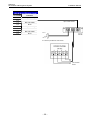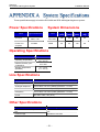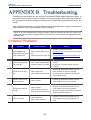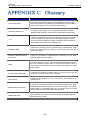
1
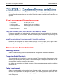
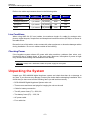
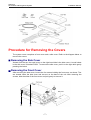
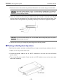
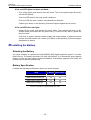
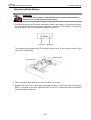
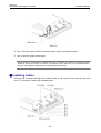
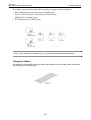
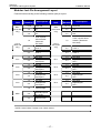
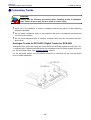
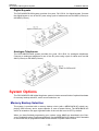
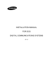
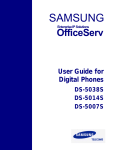
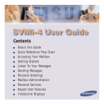
DCS-408 / 408i Installation Manual Publication Information Samsung Business Communications reserves the right without prior notice to revise information in this publication for any reason. Samsung Business Communications also reserves the right without prior notice to make changes in design or components of equipment as engineering and manufacturing may warrant. Disclaimer Samsung Business Communications is not responsible for errors or problems arising from customers not installing, programming or operating their Samsung systems as described in this manual. Copyright 2004 Samsung Business Communications All rights reserved. No part of this manual may be reproduced in any form or by any means – graphic, electronic or mechanical, including recording, taping, photocopy or information retrieval system – without express written permission of the publisher of this material. Part No.: 17260 Version 2.1 EU Declaration of Conformity (RTTE) Samsung Electronics Co., Ltd. 259 Gongdan-Dong, Gumi-City Kyungbuk, Korea, 730-030 (factory name, address) declare under our sole responsibility that the product Digital Keyphone System "DCS-408" to which this declaration relates is in conformity with RTTE Directive 1999/5/EC ( Annex II ) Low Voltage Directive 73/23/EEC:93/68/EEC EMC Directive 89/336/EEC:92/31/EEC By application of the following standards EN55022 : 1998 Inc A1: 2000* , EN55024 : 1998 +A1:2001 EN61000-3-2:1995 Inc. A1/A2:1998 EN61000-3-3:1995, EN61000-4-2:1995 Inc. A1:1998, EN61000-4-3:1996 Inc. A1:1998 EN61000-4-4:1995, EN61000-4-5:1995, EN61000-4-6:1996, EN61000-4-8:1993 EN61000-4-11:1994, AS/NZS3548:1995 EN60950 ; 1992+A1+A2+A3+A4+A11 (Manufacturer) Samsung Electronics Co., Ltd 259, Gongdan-Dong, Gumi-City Kyungbuk, Korea, 730-030 2000-12-08 TE Jang ................................................. Tae-eok Jang / General Manager ................................................................................. (place and date of issue) (name and signature of authorized person) (Representative in the EU) Samsung Electronics Euro QA Lab. Blackbushe Business Park Saxony Way, Yateley, Hampshire GU46 6GG, UK 2000-12-08 IS Lee ................................................. In-Seop Lee / Manager ............................................................................... (place and date of issue) (name and signature of authorized person) EU Declaration of Conformity (RTTE) Samsung Electronics Co., Ltd. 259 Gongdan-Dong, Gumi-City Kyungbuk, Korea, 730-030 (factory name, address) declare under our sole responsibility that the product Digital Keyphone System "DCS-408i" to which this declaration relates is in conformity with RTTE Directive 1999/5/EC ( Annex II ) Low Voltage Directive 73/23/EEC:93/68/EEC EMC Directive 89/336/EEC:92/31/EEC By application of the following standards EN55022 : 1998 Inc A1: 2000* , EN55024 : 1998 +A1:2001 EN61000-3-2:1995 Inc. A1/A2:1998 EN61000-3-3:1995, EN61000-4-2:1995 Inc. A1:1998, EN61000-4-3:1996 Inc. A1:1998 EN61000-4-4:1995, EN61000-4-5:1995, EN61000-4-6:1996, EN61000-4-8:1993 EN61000-4-11:1994, AS/NZS3548:1995 EN60950 ; 1992+A1+A2+A3+A4+A11 (Manufacturer) Samsung Electronics Co., Ltd 259, Gongdan-Dong, Gumi-City Kyungbuk, Korea, 730-030 2001-06-07 TE Jang ................................................. Tae-eok Jang / General Manager ................................................................................. (place and date of issue) (name and signature of authorized person) (Representative in the EU) Samsung Electronics Euro QA Lab. Blackbushe Business Park Saxony Way, Yateley, Hampshire GU46 6GG, UK 2001-06-11 IS Lee ................................................. In-Seop Lee / Manager ............................................................................... (place and date of issue) (name and signature of authorized person) Intended Use This telephone system is intended to provide the user with voice communication between the system extensions and connection to the public switched telephone network by digital or analogue links. The telephone system may be provided with the ability to communicate with local computer networks to provide CTI functions and features. In this case, it is capable of passing information to the computer network via a specified link. The system is powered by mains voltage and can optionally be powered by batteries. Details of all connections and power arrangements are provided in the instructions for use. It should not be used in any other way. Samsung DCS-408 & 408i Keyphone System Installation Manual Chapter 1 Keyphone System Overview................................. 1 System Features ...................................................................................................1 System Overview ..................................................................................................1 Product Safety Precautions ..................................................................................4 Chapter 2 Keyphone System Installation.............................. 5 Environment Requirements ...................................................................................5 Precautions for Installation.....................................................................................5 Unpacking the System ...........................................................................................6 Procedure for Removing Covers............................................................................7 Installation Procedure ...........................................................................................9 Grounding ...................................................................................................................... 9 Fixing the System on the Wall (Optional) ..................................................................... 11 Testing Initial System Operation .................................................................................. 12 Installing the Battery .................................................................................................... 13 Installing Cables .......................................................................................................... 15 Connecting Trunks ...................................................................................................... 18 Connecting Telephones ............................................................................................... 19 System Options .................................................................................................20 Trunk Line and Station Line Assignment ............................................................21 Digital Keyset Programming ...............................................................................22 Replacing System ROMs ....................................................................................22 Chapter 3 Connecting Additional Equipment .................... 24 Music-On-Hold/Background Music .....................................................................24 External Paging .................................................................................................25 Common Bell ......................................................................................................26 Station Message Detail Recording (SMDR) ........................................................27 PC and Remote Programming ............................................................................27 Computer Telephony (CTM-CTI) .........................................................................28 Voice Mail/Auto Attendant ...................................................................................29 Doorphone and Door Lock Release ....................................................................29 Appendix A System Specifications .................................... 31 Appendix B Troubleshooting .............................................. 32 Appendix C Glossary ........................................................... 33 –i– Samsung DCS-408 & 408i Keyphone System Installation Manual The DCS-408/DCS-408i digital keyphone system is designed to be suitable for a small office. Both the DCS-408 and DCS-408i system comprise a baseboard to which eight (8) station lines (four circuits for digital keysets and four lines for analogue telephones) can be connected. While the DCS-408 system accommodates four analogue trunk lines, the DCS-408i system accommodates two BRI lines (four channels). Moreover, the BRI2 line (two channels) of the DCS-408i system can be substituted for ISDN station lines. System Features y Simple and slim design. y Supports the Plug & Play function and is easy to install. y Displays the call list. y Supports a doorphone interface module (DPIM) connection allowing use of a doorphone. y Accommodates eight station lines. y DCS-408 accommodates four analogue trunk lines and DCS-408i accommodates four digital trunk channels. The BRI2 line (two channels) of the DCS-408i system can be substituted for ISDN station lines. NOTE: The DCS-408/DCS-408i digital keyphone system does not support add-on-modules (AOMs) or KDB-DLI and KDB-SLI keysets. System Overview General Details Item Details CPU MC68EC000 (16MHz) 16Bit Mode Memory ROM (DCS-408): 1Mbyte (2 x 27C4001) ROM (DCS-408i): 2Mbyte (4 x 27C4001) RAM: 256 kbytes (2x681000) Switch Structure 256 x 256 Time Slot SIO port RS-232C (SIO) –1– Samsung DCS-408 & 408i Keyphone System Installation Manual System Dimensions Item Height (mm) Width (mm) Depth (mm) Weight (kg) DCS-408/DCS-408i 190 350 60 2.0 DPIM 29 90 120 0.2 System Structure System Capacity DCS-408: 4 analogue trunk lines Trunk Station Music-on-hold/ Background music channel General-purpose dry contact DCS-408i: 2 BRI lines (4 channels) (BRI2 line (2 channels) can be substituted for ISDN station lines) 8 lines (4 lines for digital keysets and 4 lines for analogue telephones) 1 (internal or external) 1 SIO port 1 External page 1 CAUTION: The station lines have a fixed configuration of eight lines: 4 lines for digital keysets and 4 lines for analogue telephones. It is not possible to modify this configuration. Front View of System –2– Samsung DCS-408 & 408i Keyphone System Installation Manual System Ports (After Removing Side Cover) CO1.2/BRI1 port CO3.4/BRI2 port NOTE: Only the DCS-408i system supports the BRI feature. Rear View of System –3– Samsung DCS-408 & 408i Keyphone System Installation Manual Product Safety Precautions Precautions on Installation Do not install the unit in a location subject to moisture or wetness. ► May cause a malfunction or shorten the lifespan of components. Do not install the unit in a location near a heat source such as a heater. ► May cause a fire. Precautions on Use Do not attempt repair or modification yourself. ► Contact a service centre if repair is required. If abnormal sounds, smells or smoke come from a telephone, immediately unplug the telephone line and contact a service centre. ► If the unit is left in this state, a fire may result. Precautions on Cleaning Do not spray cleaning fluids directly on the unit, and do not clean the unit with benzene, thinner or alcohol. ► May cause a fire or an electric shock. –4– Samsung DCS-408 & 408i Keyphone System Installation Manual This chapter describes the installation procedures for the DCS-408/408i digital keyphone system, including precautions for your safety. Read this chapter carefully before installing the system. Environmental Requirements y Temperature: y Relative Humidity: y Power Specifications: y Regular Frequency: 0°–40°C (32°–104°F) Maximum 90% (non-condensing) Power supply of 60 or more watts 220VAC–240VAC, 1.6A 50Hz Keep the unit away from static electricity and electrical noise If there is a possibility of static electricity or electrical “noise” occurring where the keyphone system is installed (due to carpets, electrical machinery, etc), measures for preventing this should be put in place. Install the unit where it is not exposed to harmful conditions Be careful not to expose the system to direct sunlight, corrosive vapour, dust, regular vibration or high levels of magnetic fields generated by motors or copying machines. Precautions for Installation Selecting Location Select a location having sufficient space and levels of brightness to facilitate installation. Preventing Static Electricity The unit should not be installed in a room with carpets. To ensure safety, discharge any static electricity by touching the metal portion of a grounded object or the ground connection on the system before installing or repairing the system. In addition, for protection and reliable operation of the system, standard grounding conditions should be met. Cable Requirements Select a location which minimises the length of system cables, and ensure that all cables to and from the system are not damaged. In addition, take care to protect all cables from electromagnetic interference; for instance, by keeping them at a safe distance from cables for other equipment. –5– Samsung DCS-408 & 408i Keyphone System Installation Manual Refer to the cable requirements shown in the following table. Cables AWG Max Feet Max Metres Digital keyset 1 pr. twisted 24 (0.5 mm) 1300 400 Analogue telephone 1 pr. twisted 24 (0.5 mm) 3000 1000 Doorphone 2 pr. twisted 24 (0.5 mm) 330 100 DPIM 1 pr. twisted 24 (0.5 mm) 1000 300 Equipment Line Conditions When using AWG 24 (0.5 mm) cables, the maximum length of a cable for analogue telephones, digital keysets, doorphones and doorphone interface modules (DPIM) is as shown in the table above. Be careful not to fold cables, make contact with other equipment or otherwise damage cables during installation. Do not run cables outside of the building. Checking Power If the keyphone system shares AC power with other machines, problems from noise, malfunctioning due to voltage drops, or fire may result. Moreover, interruption of power at night may cause malfunctioning and breakdown of the battery. CAUTION: Always use a dedicated, stable AC power supply for the system Unpacking the System Unpack your DCS-408/408i digital keyphone system and check that there is no damage to any item. If you discover any damage, contact your dealer before attempting installation. Also check that you have received the following items (as well as this manual!). y DCS-408/408i Digital Keyphone System main unit y Three screws and three rawl plugs for hanging the unit on the wall y Cable for battery connection y Two AC power fuses (F1) - 250V, 2A y Two battery fuses (F2) - 125V, 3A y AC power cable y Four cable ties –6– Samsung DCS-408 & 408i Keyphone System Installation Manual Procedure for Removing the Covers The system cover comprises a front cover and a side cover. Refer to the diagram below to remove the covers. Q Removing the Side Cover Viewed from the top, the small cover on the right-hand side is the side cover. A round indent in the side cover is marked PUSH. To remove the side cover, push it to the right while gently pressing the indent. Q Removing the Front Cover After removing the side cover, loosen the four screws holding the front cover, as shown. Two are located under the side cover and two are on the base of the unit. After removing the screws, hold the sides of the front cover and pull gently to remove it. –7– Samsung DCS-408 & 408i Keyphone System Installation Manual DCS-408: Internal View DCS-408i: Internal View Q Replacing the Covers Replace the front cover by pushing it gently into place and secure it with the four screws you removed. Slide the side cover back into position until the clips engage securely. –8– Samsung DCS-408 & 408i Keyphone System Installation Manual Installation Procedure Grounding ! Grounding is essential to protect users and the keyphone system from lightning strikes, static electricity and other sources of instant high voltage. ! The AC power supply normally includes a ground connection. If for any reason it does not, separate external grounding should be done (as described here). Separate grounding should also be done if the AC power supply does include grounding but there is a problem. ! Incorrect grounding may cause a malfunction in the system. WARNING Remove the AC power cable before installing the grounding connection. If you attempt to connect a ground with the AC power cord plugged in, you are at serious risk of death or injury. NOTE: The system illustrated in this section is the DCS-408. However, this grounding procedure also applies to the DCS-408i system. Connecting an External Ground (Optional) To connect an external ground, if required, follow these steps. 1. Remove the covers of the system unit as described earlier. A green cable with a yellow stripe is soldered to the grounding end of the AC power cable connection (labelled AC INPUT) inside the system unit. The other end of the green cable is attached to the FRG lug on the power board. (Fig 1.) Cable connected to AC Input Figure 1 –9– Samsung DCS-408 & 408i Keyphone System Installation Manual 2. Cut the green cable soldered to the AC INPUT, about 2~3cm (1 inch) from the soldered end. (Fig. 2.) Figure 2 3. Push the green cable out through the rectangular hole located near to the FRG lug (Fig. 3) and insert the cable into the groove on the base of the unit (Fig. 4.). Rectangular hole Push out cable through hole Figure 3 4. Prepare an AWG 10 (2.6mm) cable for connecting to an external ground and connect it to the ground. Insert the cable into the groove on the base of the unit and connect it to the green cable you inserted in the groove at step 3. There are two ways to connect the cables: – 10 – Samsung DCS-408 & 408i Keyphone System Installation Manual O solder the ends of the two cables together, or O expose sufficient wire on both cables to twist them together tightly (Fig. 4.) Twist wires tightly Externally grounded cable Green cable Figure 4 NOTE: The cable for external grounding is not supplied with your system and should be prepared separately. The system can now be installed as a freestanding unit or may be secured to a wall using the following procedure. Fixing the System on the Wall (Optional) The unit has three grooves on the rear for fixing to a wall using the screws and rawl plugs provided. – 11 – Samsung DCS-408 & 408i Keyphone System Installation Manual 1. Drill three holes in the wall at the positions indicated for the screws using an electric drill. CAUTION: If the wall is made of plaster or brick, or if the building is prefabricated, you should fix a wooden board having a thickness of about 2 cm to the wall and drill the holes in this. Otherwise, you may damage the wall. 2. Insert the screws into the holes you drilled. If the wall is made of concrete, you will first need to insert the rawl plugs into the holes and then insert the screws into the plugs. Fasten the screws, leaving each one protruding sufficiently to be able to support the system. Hole Rawl plug Screw CAUTION: If you insert screws directly into concrete walls without using rawl plugs, the system may not be fitted securely to the wall. 3. Fix the unit securely by locating the protruding screws in the grooves. Testing Initial System Operation Check that the system operates normally before you begin connecting any cables to the unit. 1. Make sure the AC power switch is off. 2. Connect the power cable to the AC INPUT connector on the unit and to an AC mains power socket. 3. Turn on the AC power switch. Check that the red LED inside the cover on the lower righthand side is flashing. . – 12 – Samsung DCS-408 & 408i Keyphone System Installation Manual If the red LED lights but does not flash: y Turn off the power and remove the trunk board. Turn on the power again and see if the red LED flashes. If the red LED flashes, the trunk board is defective. If the red LED still does not flash, the baseboard is defective. Contact your dealer or the Samsung Technical Support department for advice. If the red LED does not light: y Switch off the power and remove the power cable. Then remove the cover as described earlier and inspect the AC power fuse (F1) next to the AC INPUT (power cable) connector. If the fuse is normal, check the power supply and output voltage. If these are normal and the red LED remains off, contact your dealer or the Samsung Technical Support department for advice. Installing the Battery Selecting the Battery You need a battery to operate the DCS-408/DCS-408i digital keyphone system if a power failure occurs. The battery required is DC 48V (6AH~40AH). If an excessively large capacity battery is used, this may cause a system breakdown. If the battery capacity is too small, the system may not operate satisfactorily. Battery Specification Consider the following specifications when you select a battery. Item Charge Discharge Minimum load current (A) 0 0.04 Maximum load current (A) 0.3 0.4 Rated output current (A) 0.1 0.2 Rated output voltage (V) 54 48 Current consumption of general telephone: 30mA – 13 – Samsung DCS-408 & 408i Keyphone System Installation Manual How to Install the Battery WARNING Ensure the mains power is switched ON before connecting the battery. Failure to do so may result in severe injury. 1. Connect the red lead of the battery connection cable to the positive (+) terminal of the battery and connect the black lead to the negative (–) terminal. If the polarity is not correctly set, the battery fuse (F2) in the power supply unit will blow. The locations of the battery fuse (F2) and AC power fuse (F1) are as shown below. Take care not to confuse them. 2. Turn on the AC power switch next to the AC INPUT connector. 3. Remove the side cover of the system as described earlier. The port for battery connection (BATT) is located at the lower right-hand side of the unit. Connect the end of the battery connection cable to this port. – 14 – Samsung DCS-408 & 408i Keyphone System Installation Manual 4. Turn off the AC power switch and check that the system operates normally. 5. Turn on the AC power switch again. NOTE: During a power failure, a battery lasts for a minimum of 4 hours if its capacity is DC 48V/6AH, and for a minimum of 8 hours if its capacity is DC 48V/12AH. The expected duration will vary with telephone usage and the charged state of the battery. Installing Cables All lines are connected through the modular jacks on the system after removing the side cover. The location of each jack is shown below. – 15 – Samsung DCS-408 & 408i Keyphone System Installation Manual The cables required for each jack differ according to the type of jacks as follows. y BRI1 / BRI2 ports: RJ-45 cable (8-pin, DCS-408i only) y CO1.2 / CO3.4 ports: RJ-11 cable (6-pin, DCS-408 only) y MISC port: RJ-11 cable (6-pin) y DLI / SLI ports: RJ-11 cable (4-pin) NOTE: These cables are not supplied with your system and should be prepared separately. Tieing the Cables You should tie all the cables using the cable ties supplied with your system after completing the cabling to the modular jacks. – 16 – Samsung DCS-408 & 408i Keyphone System Installation Manual Modular Jack Pin Arrangement Layout Connect lines according to the following modular jack pin layout. Modular Jack Pin Number 1,2,7,8 BRI1 (DCS-408i only) CO1.2 (DCS-408 only) SLI1 SLI2 SLI3 SLI4 MISC Description Modular Jack Reserved 3,6 Tx1 4,5 1,6 Pin Number 1,2,7,8 BRI2 (DCS-408i only) Description Reserved 3,6 Tx2 Rx1 4,5 Rx2 Trunk 2 power failure transfer: (ReservedNot Used) 1,6 Trunk 3 power failure transfer: (ReservedNot Used) 2,5 Trunk 4 CO3.4 (DCS-408 only) 2,5 Trunk 2 3,4 Trunk 1 3,4 Trunk 3 1,4 Not Used 1,4 Not Used 2,3 Analogue telephone port 1 2,3 Digital keyset port 1 1,4 Not Use 1,4 Not Use 2,3 Analogue telephone port 1 2,3 Digital keyset port 1 1,4 Not Used 1,4 Not Used 2,3 Digital keyset port 1 1,4 Not Used 2,3 Digital keyset port 1 DLI1 DLI2 DLI3 2,3 Analogue telephone port 1 1,4 Not Used 2,3 Analogue telephone port 1 1,6 External page 2,5 General-purpose dry contact 3,4 External music DLI4 NOTE: Power Failure Transfer is not a basic service. – 17 – Samsung DCS-408 & 408i Keyphone System Installation Manual Connecting Trunks WARNING Always take the following precautions when installing trunks or telephone lines. Failure to do so may result in death or serious injury. ! ! ! Never carry out installation of trunks or telephone lines during storms or when lightning strikes are possible. Do not install a telephone jack in a wet location if the jack is not specially manufactured for use in a wet location. Do not touch telephone lines or interface terminals when they are connected with telephone lines. Analogue Trunks for DCS-408 / Digital Trunks for DCS-408i Analogue trunks (Loop Start lines) are connected to the DCS-408 system through 6-pin, RJ11 modular jacks. Digital trunks (BRI lines) are connected to the DCS-408i system through 8pin, RJ-45 modular jacks. (See Installing Cables, above.) For the DCS-408i system, the CO3.4/BRI2 trunk line (2 channels) can be used as station lines for ISDN telephones. – 18 – Samsung DCS-408 & 408i Keyphone System Installation Manual MPD/PRS Selection and Installation NOTE: This feature is available on DCS-408 systems only. The DCS-408 system has four analogue trunk interface lines. Each trunk interface line has either a Metering Pulse Detection (MPD) function or a Polarity Reverse Detection (PRS) function as an option. When using the MPD function, insert a 12kHz or 16kHz MPD Hybrid chip into the socket of each trunk interface line and add a capacitor of 4.7nF/400V to both tip and ring. Trunk Port No. 12kHz /16kHz MPD Hybrid IC 4.7nF/400V Capacitor Port #1 P101 C102, C103 Port #2 P201 C202, C203 Port #3 P301 C302, C303 Port #4 P401 C402, C403 When using the PRS function, insert a PRS Hybrid chip into the socket of each trunk interface line and short the capacitors of both tip and ring. Trunk Port No. PRS Hybrid IC Short Port #1 P101 C102, C103 Port #2 P201 C202, C203 Port #3 P301 C302, C303 Port #4 P401 C402, C403 Connecting Telephones WARNING Always take the following precautions when installing trunks or telephone lines. Failure to do so may result in death or serious injury. ! ! ! Never carry out installation of trunks or telephone lines when there is a storm or when lightning strikes are possible. Do not install a telephone jack in a wet location if the jack is not specially manufactured for use in a wet location. Do not touch telephone lines or interface terminals when they are connected with the telephone lines. – 19 – Samsung DCS-408 & 408i Keyphone System Installation Manual Digital Keysets The DCS-408/DCS-408i system provides four ports, DLI1–DLI4, for digital keysets. Connect the digital keyset to one of the DLI ports using a pair of cables such as #24 AWG (0.5mm) or #26 AWG (0.4mm). Analogue Telephones The DCS-408/DCS-408i system provides four ports, SLI1–SLI4, for analogue telephones. Connect an analogue telephone to one of the SLI ports using a pair of cables such as #24 AWG (0.5mm) or #26 AWG (0.4mm). System Options The DCS-408/DCS-408i digital keyphone system includes several kinds of optional hardware for memory backup selection, music source selection, etc. Memory Backup Selection The system is provided with a memory backup circuit (with a MEM BACK-UP switch) employing 256K memory and a super-capacitor in case of power failure. The MEM BACK-UP switch is located on the upper right-hand side of the unit and is set to OFF by default. When you have finished programming your system (using MMCs as described in the Samsung Combined Systems Programming Manual), turn the MEM BACK-UP switch to ON. If the switch is not turned ON, all programmed data will be deleted if a power failure occurs. – 20 – Samsung DCS-408 & 408i Keyphone System Installation Manual Music Source Selection A music source selection jumper is located on the baseboard of the system unit. You can select an internal or an external music source using this jumper. As an external music source, you can connect—for example—a CD player or a radio to the MISC port of the system. Refer to Chapter 3, Connecting Additional Equipment, for a detailed description of the music source selection jumper. Trunk Line and Station Line Assignment For DCS-408 systems Trunks are assigned numbers 71 to 74. Stations are assigned numbers from 21 to 28. For DCS-408i systems Trunks are assigned numbers 71 to 74. Stations are assigned numbers from 21 to 28. The BRI2 line (2 channels) can be substituted for two station lines for ISDN terminal equipment. Numbers assigned to ports are summarised below. Port Number CO1.2/BRI1: 71~72 Trunk Port CO3.4/BRI2: 73~74 (With DCS-408i systems, the BRI2 line can be used as station lines for ISDN terminal equipment.) DLI Port (1~4) 21~24 SLI Port (1~4) 25~28 – 21 – Samsung DCS-408 & 408i Keyphone System Installation Manual Digital Keyset Programming The DCS-408/DCS-408i system can automatically program keys for a variety of Samsung digital keysets. Keysets which can be connected to these systems include: O O DCS (Euro) keysets (24-, 12- and 6-button versions) iDCS series keysets (28-, 18- and 8-button versions) Keys can be programmed with functions such as frequently dialled trunk numbers and station (extension) numbers, speed dial numbers, call pickup, paging and many more. Refer to the Samsung Combined Systems Programming Manual for more information on programming your system and keysets, and to the appropriate Samsung Keyset User Guide for operating your keysets. Replacing System ROMs You need to replace system ROM chips when upgrading the system program or fixing bugs in the program. Before replacing the system ROMs, read this section carefully. If there are any problems, or if you are unsure of anything, contact your dealer or the Samsung Technical Support department for advice. Replace the ROMs as follows. 1. Switch off the mains power and remove the power cable. 2. Remove the side cover of the system unit as described earlier. If you want to reprogram the new system (using MMCs) when you’ve finished installing the new ROMs, set the MEM BACK-UP switch to OFF to initialise the previous system data. 3. Remove the front cover of the system unit as described earlier 4. If an external battery is installed, remove it. 5. Locate the ROMs to be replaced. There are four ROMs on the baseboard, as shown in the diagram. NOTE: Older versions of the 408 may have only two ROMS: EVEN1 and ODD1. – 22 – Samsung DCS-408 & 408i Keyphone System Installation Manual 6. Remove the ROMs using a chip extractor and keep them safe for reinstallation in case of emergency. 7. Install the new ROMs with care, in the correct orientation, in the designated locations. 8. Reconnect the power cable, switch on the power and check that the system is operating correctly. If not, remove the new ROMs, re-install the old ones and contact your dealer or the Samsung Technical Support department for advice. 9. Set the MEM BACK-UP switch to ON if you switched it off in step 3. 10. If an external battery was installed, reconnect it. 11. Replace the front and side covers of the system unit. Reprogram the system (using MMCs) if necessary. – 23 – Samsung DCS-408 & 408i Keyphone System Installation Manual This chapter describes how to connect the following equipment: Music-on-Hold/Background music, external paging, common bell, serial printer for SMDR, a PC for remote programming, a Computer Telephony Module, Voice Mail System/Automated Attendant, and a doorphone. You will see occasional references to MMCs for programming system features: in these cases, refer to the Samsung Combined Systems Programming Manual for descriptions of the MMCs. Music-On-Hold/Background Music You can select an internal music source or an external music source by moving a jumper on the baseboard of the DCS-408/408i system. Various media such as a CD player and a radio can be used as the external music source. You can program the system such that music can be received by the system during conversation over a trunk or a station. In this case, when the music-on-hold key of the digital keyset is pressed, the system sends tone or internal music to a trunk (as set in MMC 408, Assign Trunk Music On Hold Source) or a station (as set in MMC 309, Assign Station Music On Hold). In addition, a digital keyset can be served with an external music source or an internal music source as background music (as set in MMC 308, Assign Background Music Source). An internal music source is selected by default. To select an external source, follow these steps. 1. Remove the side cover and the front cover from the system unit. (This is described in Chapter 2.) 2. A small jumper (labelled MOH) is provided at the lower right-hand side of the baseboard. The jumper is located over the [INT] pin by default. To use an external music source, lift the jumper off the pins and replace it on the [EXT] pin. (The diagram below shows the DCS-408 system. The jumper position is the same for the 408i.) – 24 – Samsung DCS-408 & 408i Keyphone System Installation Manual 3. Connect an external music source (such as a CD player or radio) to the music source pins of the MISC port. Refer to the following table showing the arrangement of the modular jack pins for the MISC port. MISC (RJ-11 [6-pin] Modular Jack) Pin number Features 1 6 External page 2 5 General-purpose dry contact 3 4 Music source External Paging The keyphone system is equipped with an interface for external paging. It can be connected to customer-provided paging equipment. The interface is designed to match 600 Ohm and an impedance matching transformer may be required if the impedance of the paging equipment is not 600 Ohm. Using one pair twisted-wire cable, connect the customer-provided paging equipment to the external page pins of the MISC port. Installing External Paging 1. Connect external paging equipment to the external page pins of the MISC port. 2. Assign the page zone number and select the member number (see MMC 605, Assign External Page Zone). 3. The following table shows the arrangement of pins for the modular jack for connection of external paging equipment. MISC (RJ-11 [6-pin] Modular Jack) Pin number Features 1 6 External Page 2 5 General-purpose dry contact 3 4 Music source CAUTION: Do not connect external paging equipment directly to a commercial AC power supply. This can result in system breakdown or fire. – 25 – Samsung DCS-408 & 408i Keyphone System Installation Manual Common Bell If you connect a common bell to the general-purpose dry contact pins of the MISC port, the common bell can receive a call signal as if it is one of the stations. You can select a continuous bell or an interrupted bell using MMC 204, Common Bell Control. When an interrupted bell is selected, a trunk call signal (1 second ON / 2 seconds OFF) should be designated. After connecting a common bell, you can designate a station group through MMC 601, Assign Station Group, using a common bell code. NOTE: You can use a common bell for receiving a call from a particular direct trunk. A relay controlling the common bell is used with low voltage and low current so that the common bell can only be used under 5Vdc and 40mA. Installing a Common Bell 1. Connect a common bell to the general-purpose dry contact pins of the MISC port. 2. Set the common bell controlling method to a continuous type or an interrupted type (MMC 204). 3. Assign the common bell to a particular station group (MMC 601). 4. Designate the station group where the common bell is included as receiving a call from a particular direct trunk. 5. The following table shows the arrangement of pins for the modular jack when connecting a common bell. MISC (RJ-11 [6-pin] Modular Jack) Pin number Features 1 6 External page 2 5 General-purpose dry contact 3 4 Music source CAUTION: Do not connect a common bell directly to a commercial AC power supply. This can result in system breakdown or fire. – 26 – Samsung DCS-408 & 408i Keyphone System Installation Manual Station Message Detail Recording (SMDR) Connect a serial printer to the SIO serial port on the system using an RS-232C cable. Use a shielded computer cable longer than 5m. The maximum allowed length of the cable is 15m. SMDR output printer options are set in MMC 725, SMDR Options. Parameters are set in MMC 804, System I/O Parameter. Cable connections are as follows. SIO Port RXD(2) TXD(3) GND(5) Printer Port <----------------------------------------------TXD(2) -----------------------------------------------> RXD(3) ------------------------------------------------GND(7) PC and Remote Programming NOTE: This feature is applicable to the DCS-408i system only. To program the system via a personal computer (PC) or customer-provided modem (remote programming), connect a modem or a PC to the serial (SIO) port of the system using an RS232C cable. Refer to diagram above. The PC must be equipped with the proprietary program, PCMMC. Before connecting the PC or modem: Ensure that the power to the PC/modem and keyphone system is turned OFF. Remove the external battery, if installed. Otherwise, the keyphone system and PC/modem may be severely damaged. NOTE: When the PC or modem need to be more than 5m away from the keyphone system, shielded computer cable is required. The cable must not exceed 15m. – 27 – Samsung DCS-408 & 408i Keyphone System Installation Manual MMC 804 It is necessary to set the Service Type of the SIO port as ‘PCMMC’ in MMC 804 in order to program the system via a PC. Parameters related to PCMMC and remote programming are also set in MMC 804. The pin connections from the SIO port to the PC/modem are as follows. PCMMC SIO Port 9-PIN RXD(2) -----------------------------------------------TXD(3) -----------------------------------------------GND(5) ------------------------------------------------ PC 25-PIN 9-PIN TXD(3) TXD(3) RXD(2) RXD(2) GND(7) GND(5) Remote Programming SIO Port 9-PIN RXD(2) TXD(3) GND(5) DTR(4) --------------------------------------------------------------------------------------------------------------------------------------------------------------------------------- MODEM 25-PIN TXD(3) RXD(2) GND(7) DTR(20) Computer Telephony (CTM-CTI) NOTE: The Computer Telephony Module (CTM) and Computer Telephony Integration (CTI) feature are applicable to the DCS-408i system only. The DCS CTM is required to support CTI (TAPI) in the system. The CTM has a PC interface (DB9) and a DLI connection which can be connected to any DLI port of the keyphone system. A PC can be connected to the module via the DB9 (9-pin serial) connector. Connect the CTM to a PC and a digital keyset as follows. ➊ Prepare one-pair twisted cables. ➋ Connect each CTM to the DLI port of your choice via the modular jack marked 'DLI IN'. ➌ Connect the CTM to a digital keyset via the modular jack marked 'KTS OUT'. NOTE: A special PC software package is required to run CTI (TAPI) and you should read the documentation supplied with the software package in order to install and use the software. Contact your dealer for further information. CAUTION: You cannot install the CTM outdoors. – 28 – Samsung DCS-408 & 408i Keyphone System Installation Manual The pin connections from the CTM to the PC are as follows. CTM TXD(2) RXD(3) GND(5) ------------------------------------------------------------------------------------------------------------------------------------------- PC COM1 COM2 9-PIN 25-PIN RXD(2) RXD(3) TXD(3) TXD(2) GND(5) GND(7) Voice Mail/Auto Attendant If you connect a voice mail system or automated attendant to a corresponding circuit of the keyphone system, the common bell can receive a call signal as if it is one of the stations. Set a port in MMC 207, Assign VM/AA Port, and set the necessary parameters in MMC 726, VM/AA Options. You should connect voice mail/auto attendant to the SLI4 port only. The following table shows the arrangement of pins for the modular jack when connecting voice mail/auto attendant. SLI4 Port (RJ-45 [4-pin] Modular Jack) Pin number Features 1, 4 Not Used 2, 3 SLI4 Voice Mail/ Auto Attendant NOTE: Always connect the voice mail/auto attendant to the SLI4 port. Connecting the voice mail/auto attendant to an SLI1–SLI3 port may cause critical errors. Doorphone and Door Lock Release Connect a Doorphone Interface Module (DPIM) to a doorphone using a pair of #24 AWG or #26 AWG cables. Then, connect the DPIM to a DLI port of your choice using a pair of #24 AWG or #26 AWG cables. Refer to the section Installing Cables in Chapter 2 for details of the connection between the DPIM and the DLI port. If you want to use the automatic door lock release, connect the LOCK port on the DPIM to the door lock release. NOTE: Use only a Samsung 4-line keyset doorphone for this feature, which you can purchase separately. The following table and diagram show the arrangement of pins for the modular jack when connecting a doorphone and door lock release to the DPIM. – 29 – Samsung DCS-408 & 408i Keyphone System Installation Manual DLI port (RJ-45 [4-pin] Modular Jack) Pin number Features 1,4 NC (not used) DLI1 2,3 1,4 2,3 NC (not used) DLI2 1,4 NC (not used) 2,3 DLI3 1,4 NC (not used) 2,3 DLI4 1 pair modular cables Pin 6 Pin 1 To customer-provided door lock release I pair modular cables – 30 – Samsung DCS-408 & 408i Keyphone System Installation Manual These specifications apply to both the DCS-408 and DCS-408i digital keyphone system. Power Specifications Item System Dimensions Specifications Item Height (mm) Width (mm) Depth (mm) Weight (kg) AC Input 220~240 VAC, 50Hz, 1.6A DCS-408/ DCS-408i 190 350 60 2.0 Maximum Power Consumption 44 Watts DPIM 29 90 120 0.2 Operating Specifications Item Specifications Operating Temperature 0°~40°C (32°~104°F) Relative Humidity (noncondensing) 10%~90% Storage Temperature (Min/Max) -10°~+50°C (14°~122°F) Line Specifications Item Specifications Digital Keyset 2-line cable, max 400m (1300ft) (AWG #24 – 0.5 mm) Analogue Telephone 2-line cable, max 1km (3000ft) (AWG #24 – 0.5 mm) DPIM 2-line cable, max 300m (1000ft) (AWG #24 – 0.5 mm) Doorphone 2-line cable, max 100m (330ft) (AWG #24 – 0.5 mm) Printer RS-232C cable, 15m (50 ft) Other Specifications Item Specifications External music source input characteristics Impedance 600 Ohm, maximum 350 mV External Page Impedance 600 Ohm – 31 – Samsung DCS-408 & 408i Keyphone System Installation Manual Problems may arise while you are using the DCS-408/DCS-408i digital keyphone system. In rare cases this may be the result of a serious fault in the system. More commonly, problems can be resolved quickly and easily by following the troubleshooting tips described in this appendix. If the problem persists after you have taken the steps described here, contact your dealer for advice and refer servicing to qualified service personnel. NOTE: If you are not familiar with using the system, Samsung recommends that you contact your dealer and refer servicing to qualified service personnel even if the problem and suggested actions are listed here. Common Problems Condition Suspected cause Actions - Check power cable connection. DCS-408/DCS-408i digital keyphone system is not powered ON. - Fault in power cable connection - Check the fuses (check the AC input and the DC output) - Fault in the power supply unit - Check whether the red LED under the front cover is flashing. 2 Nothing is displayed on LCD of keyset. - Fault in DCS-408/408i digital keyphone system connection 3 Keyset does not operate. - Fault in the keyset 4 Keyset volume control does not operate. 1 5 Keyset ringer does not operate. 6 Tone is not heard. - Fault in data communication - Check if the modular jack has been removed. - Check if the connecting cables are shortcircuiting. - Replace the keyset with another one and check whether the new one operates. - Check the ports to determine whether voltage output is normal. - Fault in keyset - Replace the keyset with another one and check whether the new one operates. - Fault in keyset - Replace the keyset with another one and check whether the new one operates. - Fault in the SLI ports when using an analogue telephone - Fault in the keyset - Fault in line connection – 32 – - Check ring output if the problem occurs with another analogue telephone. - Replace the keyset with another one and check whether the new one operates correctly. Samsung DCS-408 & 408i Keyphone System Installation Manual Term Description AUXILIARY RING A function which allows a station to be designated as one of a pair with another station, thus allowing the two stations to ring simultaneously when there is an incoming call on either station. BATTERY (BACK-UP) An auxiliary power supply unit for temporarily operating the DCS408/408i digital keyphone system if the mains power is interrupted. CALL Indicates an interval from the moment the phone rings to the completion of conversation (in the case of an incoming call) or an interval from the moment a telephone number is dialled to the completion of conversation (in the case of an outgoing call). COMMON BELL A feature for making a group of phones ring simultaneously when there is an incoming call, by assigning a bell to the group when designating the group. DIGITAL LINE INTERFACE (DLI) PORT A port for connecting a digital keyset exclusively for the DCS408/408i digital keyphone system. DISA A function allowing a user to call the DCS-408 digital keyphone system from outside and then make a call using the system. When a user makes a call abroad using this function, call charges are billed to the system. DO NOT DISTURB (DND) A function for blocking incoming calls to a user’s phone from the moment the function is set until it is released. IDLE STATE A state where a telephone is not in use; that is, the handset is onhook (hung up). MEM BACK-UP SWITCH A switch for connecting the battery and supplying power to the DCS408/408i digital keyphone system if power is interrupted. This retains system data for a predetermined time. The switch must be turned ON after data is entered using MMC programming. MODULAR JACK A jack facilitating connection of various circuits to the DCS-408/408i digital keyphone system. – 33 – Samsung DCS-408 & 408i Keyphone System Installation Manual Term Description PORT (CIRCUIT) A circuit for connecting and operating an individual trunk, digital keyset or an analogue telephone. POWER FAILURE TRANSFER (PFT) A function for directly connecting some trunks to particular analogue telephones when power is interrupted to the DCS-408/408i digital keyphone system, thereby allowing a call to be made regardless of the status of the system. RING A sound provided to inform a user of an incoming call. There are a number of different rings: station/trunk ring, off-hook ring provided while a call is being connected, etc. SINGLE LINE INTERFACE (SLI) PORT A port for connecting an analogue telephone generally used at home or in the office. STATION A telephone line connecting a DCS-408/408i digital keyphone system and a user’s phone. STATION MESSAGE DETAIL RECORDING (SMDR) A function for outputting information for trunk calls through the DCS408/408i digital keyphone system using additional equipment such as a PC or a printer. SYSTEM PROGRAMMING (MMC) Programs (Man Machine Code) for setting up the operating system with the various functions and parameters provided by the DCS408/408i digital keyphone system, to be suitable for a user’s requirements. TONE Sound for informing a user of the operating state of the DCS408/408i digital keyphone system. There are a number of tones: dial tone, ring back tone, busy tone, etc. TRUNK A telephone line connecting a telephone exchange and the DCS408/408i digital keyphone system. VOICE MAIL (VMS) A system for recording and storing voice messages. – 34 – Samsung Business Communications Brookside Business Park, Greengate, Middleton, Manchester M24 1GS