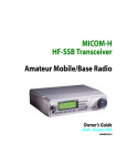
1
MICOM-2ES/2RS/2TS ALE
HF-SSB TRANSCEIVERS
Supplement to Owner’s Guide
best radio for worst events
6886872J01
COMMERCIAL WARRANTY (STANDARD)
Motorola radio communications products are warranted to be free from defects in material and
workmanship for a period of ONE (1) YEAR, (except for crystals and channel elements which
are warranted for a period of ten (10) years) from the date of shipment. Parts, including
crystals and channel elements, will be replaced free of charge for the full warranty period but
the labor to replace detective parts will only be provided for One Hundred-Twenty (120) days
from the date of shipment. Thereafter purchaser must pay for the labor involved in repairing
the product or replacing the parts at the prevailing rates together with any transportation
charges to or from the place where warranty service is provided. This express warranty is
extended by Motorola Communications and Electronics Inc., 1301 E. Algonquin Road,
Schaumburg, Illinois 60196, to the original purchaser only, and only to those purchasing for
purpose of leasing or solely for commercial, industrial, or governmental use.
THIS WARRANTY IS GIVEN IN LIEU OF ALL OTHER WARRANTIES EXPRESS OR
IMPLIED WHICH ARE SPECIFICALLY EXCLUDED, INCLUDING WARRANTIES OF
MERCHANTABILITY OR FITNESS FOR A PARTICULAR PURPOSE. IN NO EVENT
SHALL MOTOROLA BE LIABLE FOR INCIDENTAL OR CONSEQUENTIAL
DAMAGES TO THE FULL EXTENT SUCH MAY BE DISCLAIMED BY LAW.
In the event of a defect, malfunction or failure to conform to specifications established by
Seller, or if appropriate, to specifications accepted by Seller in writing, during the period
shown. Motorola, at its option, will either repair or replace the product or refund the purchase
price thereof, and such action on the part of Motorola shall be the full extent of Motorola's
liability hereunder.
This warranty is void if:
a. The product is used in other than its normal and customary manner.
b. The product has been subject to misuse, accident, neglect or damage.
c. Unauthorized alterations or repairs have been made, or unapproved parts used in the
equipment.
This warranty extends only to individual products, batteries are excluded, but carry their own
separate limited warranty. Because each radio system is unique, Motorola disclaims liability
for range, coverage, or operation of the system as a whole under this warranty except by a
separate written agreement signed by an officer of Motorola.
Non-Motorola manufactured products are excluded from this warranty, but subject to the
warranty provided by their manufacturers, a copy of which will be supplied to you on specific
written request.
To obtain performance of this warranty, purchaser must contact
mobat_support@mobatUSA.com.
This warranty applies only within the United States.
COMPUTER SOFTWARE COPYRIGHTS
The Motorola products described in this instruction manual may include copyrighted Motorola
computer programs stored in semiconductor memories or other media. Laws in the United
States and other countries preserve for Motorola certain exclusive rights for copyrighted
computer programs, including the exclusive right to copy or reproduce in any form the
copyrighted computer program. Accordingly, any copyrighted Motorola computer programs
contained in the Motorola products described in this instruction manual may not be copied or
reproduced in any manner without the express written permission of Motorola. Furthermore,
the purchase of Motorola products shall not be deemed to grant either directly or by
implication, estoppel, or otherwise, any license under the copyrights, patents or patent
applications of Motorola, except for the normal non-exclusive, royalty free license to use that
arises by operation of law in the sale of a product.
best radio for worst events
MICOM-2ES/2RS/2TS ALE
HF-SSB TRANSCEIVER
Motorola
1720 West Paul Dirac Drive,
Tallahassee 32310 FL, USA
Supplement to
Owner’s Guide
Cat. No. 6886872J01
Warnings, Cautions and Notes
Warnings, Cautions and Notes
The following notations are used to place special emphasis on procedures, or to call
attention to precautionary measures.
An operating procedure, practice and so forth, which if not
followed correctly, could result in personal injury, or loss of life.
Warning
An operating procedure, practice and so forth, which if not followed
correctly, could result in damage to, or destruction of equipment.
Important
An operating procedure, condition and so forth, to which special
attention should be paid.
Note
General Safety Precautions
The following are general safety precautions that are not related to any specific
procedures and therefore do not appear elsewhere in this publication. These are
recommended precautions that personnel must understand and apply, in addition to
the precautions listed in the Information for Safe, Efficient Operation section.
Warning
High
Voltage
Do not touch the antenna and the RF connectors when the
transceiver operates.
During transmission, high RF voltages appear at the RF
connectors, the antenna cables, and on the antenna itself. These
voltages may cause severe injury or even death on contact.
Operating and maintenance personnel must be familiar with the
applicable safety requirements before attempting to install or
operate the transceiver. Severe injury or death could result from
failure to comply with the safety practices.
_________________________________________________________________________________________________
i
MICOM-2ES/2RS/2TS ALE Supplement to Owner’s Guide
Information for Safe, Efficient Operation
Product Safety and RF Exposure for Mobile
Two-Way Radios Installed in Vehicles or as Fixed
Site Control Stations
Caution
BEFORE USING THIS RADIO, READ THIS BOOKLET WHICH
CONTAINS IMPORTANT OPERATING INSTRUCTIONS FOR
SAFE USAGE AND RF ENERGY AWARENESS AND CONTROL
INFORMATION FOR COMPLIANCE WITH RF ENERGY
EXPOSURE LIMITS IN APPLICABLE NATIONAL AND
INTERNATIONAL STANDARDS.
The information provided in this document supersedes the general safety information
contained in user guides published prior to February 2002.
Compliance with RF Energy Exposure Standards
NOTICE
This radio is intended for use in occupational/controlled
applications where users have been made aware of the potential
for exposure and can exercise control over their exposure. This
radio device is NOT authorized for general population,
consumer or similar use.
Motorola, Inc. 2003
8000 W. Sunrise Blvd., Ft. Lauderdale, FL 33322
Printed in USA. 7/03
ii
________________________________________________________________________________________________
Warnings, Cautions and Notes
Federal Communication Commission Regulations
The FCC has established limits for safe exposure to radio frequency (RF)
emissions from mobile two-way radios. The FCC requires manufacturers to
demonstrate compliance with RF exposure limits before mobile two-way radios
can be marketed In the U.S. When two-way radios are approved for
occupational/controlled environment exposure limits, the FCC requires users to
be fully aware of, and exercise control over, their exposure. Awareness and
control of RF exposure can be accomplished by education or training through
appropriate means such as information and instructions in user manuals or
safety booklets, or other appropriate means. This user safety booklet includes
useful information about RF exposure and helpful instructions on how to
control your RF exposure.
Your Motorola two-way radio is designed and tested to comply with a number of
national and international standards and guidelines (listed below) regarding human
exposure to radio frequency electromagnetic energy. This radio complies with the
IEEE (FCC) and ICNIRP exposure limits for occupational/controlled RF
exposure environments at usage factors of up to 50% talk-50% listen. In terms of
measuring RF energy for compliance with FCC exposure guidelines, your radio
radiates measurable RF energy only while it is transmitting (during talking), not
when it is receiving (listening) or in standby mode.
Your Motorola two-way radio complies with the following RF energy exposure
standards and guidelines:
•
United States Federal Communications Commission, Code of Federal
Regulations; 47CFR part 2 sub-part J
•
American National Standards Institute (ANSI) / Institute of Electrical and
Electronic Engineers (IEEE) C95.1-1992
•
Institute of Electrical and Electronic Engineers (IEEE) C95.1-1999 Edition
•
International Commission on Non-Ionizing Radiation Protection (ICNIRP)
1998
•
Ministry of Health (Canada) Safety Code 6: Limits of Human Exposure to
Radiofrequency Electromagnetic Fields in the Frequency Range from 3 kHz
to 300 GHz, 1999
•
Australian Communications Authority Radiocommunications
(Electromagnetic Radiation – Human Exposure) Standard, 2001
•
ANATEL, Brasil Regulatory Authority, Resolution 256 (April 11, 2001).
Additional Requirements for SMR, Cellular and PCS Product Certification.
_________________________________________________________________________________________________
iii
MICOM-2ES/2RS/2TS ALE Supplement to Owner’s Guide
Compliance and Control Guidelines and Operating Instructions
for Mobile Two-Way Radios Installed in Vehicles
To control your exposure and ensure compliance with the
occupational/controlled environment exposure limits, always adhere to the
following procedures:
•
To transmit (talk), push the Push-To-Talk (PTT) button; to receive,
release the PTT button. Transmit only when people outside the vehicle
are at least 7 feet from a properly installed, externally-mounted antenna.
•
Install mobile antennas at the center of the roof or the center of the trunk
deck per specific guidelines and instructions in the Radio Installation
Manual. These mobile antenna installation guidelines are limited to metal
body vehicles.
Use only the Motorola-approved, supplied antenna or a Motorolaapproved replacement antenna. Use of non-Motorola-approved antennas,
modifications, or attachments could damage the radio and may violate FCC
regulations.
Compliance and Control Guidelines and Operating Instructions for Mobile
Two-Way Radios Installed as Fixed Site Control Stations
If mobile radio equipment is installed at a fixed location and operated as a control
station or as a fixed unit, the antenna installation must comply with the following
requirements in order to ensure optimal performance and compliance with the RF
energy exposure limits in the standards and guidelines listed in the Federal
Communication Commission Regulations section.
iv
•
The antenna should be mounted outside the building on the roof or a tower if
at all possible.
•
As with all fixed site antenna installations, it is the responsibility of the licensee to
manage the site in accordance with applicable regulatory requirements and may
require additional compliance actions such as site survey measurements, signage,
and site access restrictions in order to ensure that exposure limits are not
exceeded.
________________________________________________________________________________________________
Warnings, Cautions and Notes
Electromagnetic Interference/Compatibility
Note
Nearly every electronic device is susceptible to electromagnetic
interference (EMI) if inadequately shielded, designed, or
otherwise configured for electromagnetic compatibility. It may be
necessary to conduct compatibility testing to determine if any
electronic equipment used in or around vehicles or near fixed site
antenna is sensitive to external RF energy or if any procedures
need to be followed to eliminate or mitigate the potential for
interaction between the radio transmitter and the equipment or
device.
Facilities
To avoid electromagnetic interference and/or compatibility conflicts, turn off your
radio in any facility where posted notices instruct you to do so. Hospitals or
health care facilities may be using equipment that is sensitive to external RF energy.
Vehicles
To avoid possible interaction between the radio transmitter and any vehicle electronic
control modules, for example, ABS, engine, or transmission controls, the radio
should be installed only by an experienced installer and that the following
precautions be used when installing the radio:
1.
2.
3.
Refer to the manufacturer's instructions or other technical bulletins for
recommendations on radio installation.
Before installing the radio, determine the location of the electronic control modules
and their harnesses in the vehicle.
Route all radio wiring, including the antenna transmission line, as far away as possible
from the electronic control units and associated wiring.
Driver Safety
Check the laws and regulations on the use of radios in the area where you drive.
Always obey them.
When using your radio while driving, please:
•
Give full attention to driving and to the road.
•
Pull off the road and park before making or answering a call if driving
conditions so require.
_________________________________________________________________________________________________
v
MICOM-2ES/2RS/2TS ALE Supplement to Owner’s Guide
Operational Warnings
For Vehicles with an Air Bag
Warning
Do not mount or place a mobile radio in the area over an
air bag deployment area. Air bags inflate with great force.
If a radio Is placed in the air bag deployment area and the
air bag inflates, the radio may be propelled with great force
and cause serious injury to occupants of the vehicle.
Potentially Explosive Atmospheres
Turn off your radio prior to entering any area with a
potentially explosive atmosphere. Sparks in a potentially
explosive atmosphere can cause an explosion or fire
resulting in bodily injury or even death.
The areas with potentially explosive atmospheres include
fueling areas such as below decks on boats, fuel or chemical
transfer or storage facilities, and areas where the air
contains chemicals or particles such as grain, dust or metal
powders. Areas with potentially explosive atmospheres are
often, but not always, posted.
Blasting Caps and Blasting Areas
Warning
vi
To avoid possible interference with blasting operations, turn
off warning your radio when you are near electrical blasting
caps, in a blasting area, or in areas posted: "Turn off twoway radio". Obey all signs and instructions.
For radios installed in vehicles fueled by liquefied petroleum
gas, refer to the (U.S.) National Fire Protection Association
standard, NFPA 58, for storage, handling, and/or container
information. For a copy of the LP-gas standard, NFPA 58,
contact the National Fire Protection Association, One
Battery Park, Quincy, MA.
________________________________________________________________________________________________
Table of Contents
Table of Contents
Page
Introduction .................................................................................................... 1
New Model Information ................................................................................. 1
44-Pin Accessories Connector........................................................................ 1
Functional Enhancements............................................................................... 4
Additional MICOM-2 Features ...................................................................... 8
Display Modes .......................................................................................... 8
Receive Level Bar..................................................................................... 8
VFO Operation ......................................................................................... 9
BandWidth Filters..................................................................................... 10
New Channel/Frequency/Scan/Link Mode Features ................................ 12
New ALE Features.................................................................................... 14
VP-116 Mini Voice Privacy Unit Interface (Optional)............................. 20
PPS-100 Pre-Post Selector (Optional) ...................................................... 29
_________________________________________________________________________________________________
vii
MICOM-2ES/2RS/2TS ALE Supplement to Owner’s Guide
viii
________________________________________________________________________________________________
Introduction
Introduction
This Supplement to the “MICOM-2E/2R ALE HF-SSB Transceiver Owner’s Guide”,
Publication 68P02952C60-A, provides you with information on additional features,
options and MICOM-2 models, which are not documented in the Owner’s Guide.
The information presented in this Supplement covers the new versions (Version CK)
of the MICOM-2E/2RS/2TS ALE HF-SSB transceivers. The new versions use
enhanced hardware and provide additional ALE capabilities.
Externally, the new versions are similar to the previous MICOM-2. However,
changes have been made in the wiring of the 44-pin accessories connector located on
the rear panel, relative to the 44-pin connector used by the previous versions.
The information appearing in this Supplement is intended for use with the Owner’s
Guide, MICOM-2E/2RS/2TS ALE HF-SSB Transceivers, Publication
68P02952C60-A.
New Model Information
The new transceiver versions have been assigned new model numbers, as follows:
MICOM-2ES
Model M80AMNOKV5CK
MICOM-2ETS Model M81AMNOKV5CK
MICOM-2RS
Model M85AMNOKV5CK
44-Pin Accessories Connector
Table 1 lists the current functions of the 44-pin accessories connector, J5.
Asterisks * appear in the Designation column next to the pins whose function has
changed, relative to previous equipment versions.
Notes
1. The information appearing in Table 1 supersedes any previous
information provided in the Owner’s Guide (Publication
68P02952C60-A).
2. You can continue using the fixed adapter accessory for
MICOM-2ES, MICOM-2ETS and MICOM-2RS (Part No.
09MB000011). This accessory interfaces between the 44-pin
connector and older 25-pin accessories.
_________________________________________________________________________________________________
1
MICOM-2ES/2RS/2TS ALE Supplement to Owner’s Guide
Table 1. 44-Pin Accessories Connector, Pin Functions
Pin
2
Designation
Description
1
SPKR-
Differential output to the external 8Ω, 8W speaker
2
STOP SCAN
Digital control input for stop scan function
3
SPKR+
Differential output to the external 8Ω, 8W speaker
4
EXT RX AUDIO+
5
EXT RX AUDIO-
Differential received audio output (0 dBm; 600Ω; not
controlled by volume, but affected by squelch)
6
EXT TX AUDIO+
7
EXT TX AUDIO-
8
PTT IN VOICE
Differential transmit audio input (600Ω input impedance,
0 dBm is required for full power)
Transmission command (short to ground) for voice
signals
9
PTT IN DATA
Transmission command (short to ground) for data signals
10
PTT IN CW
Transmission command (short to ground) for CW
(Morse) signals
11
SW A+
Primary DC voltage current limited output (max 1A)
12
DSI/KW C C
BDM – Data serial in/kW amplifier channel change
13
KW ON/OFF
kW amplifier power on/off output
14
REV CLOSE LOOP *
Close the loop of ALC radio (input)
15
RXA
Receive input (point-to-point protocol to host/HLC)
16
TXA
Transmit output (point-to-point protocol to host/HLC)
17
EX RESET
External RESET input (for BDM)
18
GND
Ground
19
KW PTT
PTT output to kW amplifier
20
EXT ALARM
External alarm output (open collector, pulled to ground
when external alarm is activated
21
VPP
Flash programming voltage, input to BDM
22
DSC/KW_ALC
BDM – Data serial clock/kW amplifier ALC
23
SQ GATE
Squelch open/closed indication output
24
DSO/FAN ON/OFF
BDM – Data serial out/Fan control
25
FREEZE/KW TU
BDM – Freeze/kW amplifier tune
26
GND
Ground
_________________________________________________________________________________________________
44-Pin Accessories Connector
Table 1. 44-Pin Accessories Connector, Pin Functions (Cont’d)
Pin
Designation
Description
27
FWD CLOSE LOOP *
ALC radio loop closure input
28
RXC *
Receive input (point-to-point protocol to host/HLC)
29
TXB
RS-232 transmit output to VP-116, PPS, 500W, ASTIC
30
AMP REV *
Maintain constant power at 500W transceiver output
31
RXD *
Receive input (point-to-point protocol to host/HLC)
32
TX AUDIO OUT
Input to baseband TX path
33
RXB
RS-232 protocol receive input to VP-116, PPS, 500W,
ASTIC
34
RX AUDIO OUT
Input to baseband RX path
35
RX AUDIO IN
Output from baseband RX path
36
AMP FWD *
Maintain constant power at 500W transceiver output
37
VP PTT *
PTT output (active low)
38
TXD *
Transmit output (point-to-point protocol to host/HLC)
39
TXC *
Transmit output (point-to-point protocol to host/HLC)
40
TX AUDIO IN
Output from baseband TX path
41
EXT RX AUDIO(2)+
Audio out from ISB hybrid
42
EXT TX AUDIO(2)–
Audio out from ISB hybrid
43
EXT RX DATA– *
Baseband output (0 dBm, 600 Ω)
44
EXT RX DATA+ *
Baseband output (0 dBm, 600 Ω)
_________________________________________________________________________________________________
3
MICOM-2ES/2RS/2TS ALE Supplement to Owner’s Guide
Functional Enhancements
Figure 1 through Figure 5 present the menus of the new MICOM-2 CK transceiver
versions. The main enhancements are described below.
Note
MICOM-2 transceivers with internal GPS receiver (optional) have
extended FREQ and CH menus. See Figure 7 for a description of the
GPS menus.
Main Menu
MORE
CHAN
1
2
3
4
FREQ
LOCK
BIT
SMPX
DPLX
RXO
TXO
FULL
CHAN
L.RF
ALE = YES
PROG
LOCK
PSW
PSW
PSW
OLD
DIM
LEVEL
0123
RAD
ALE = NO
SCAN
ALE
ALE
NET
ENTER
NO
STOP
SLOW
FAST
A
GRP
B
C
D
E
LANG
ENGLISH
FRENCH
ESPA
Figure 1. Main Menu
4
_________________________________________________________________________________________________
Functional Enhancements
CH Mode
Only for ALE
MORE
BAND
LSB
USB
SQ
MORE
PWR
DSP
ON
OFF
CLAR
NF
.. -200
.
.. ...
.. OFF
.
.. ...
+200
SSB
AME
PLT
AGC
BW
SLOW
FAST
OFF
2.1
2.7
3.0
3.3
LSM
CW
RCLV
CALL
See Note
ON
OFF
NB
ON
OFF
ON
OFF
LQA
MON
BDIR
SOUND
SEND
PAGE
ON
OFF
MORE
MULT
..
..
CLIP
ATTN
MODE
LOW
MED
HIGH
MAX
MORE
ALL
SEND
PAGE
NET
SEND
PAGE
CHAN
Figure 2. Channel (CH) Menu
Frequency
Change
FREQ Mode
−−>
<−−
MORE
T/R
SMPX
DPLX
RXO
TXO
BAND
LSB
USB
SQ
ON
OFF
DSP
PWR
CLAR . -200
.. ...
. .
.. OFF
.
.. ...
+200
NF
..
..
CLIP
ON
OFF
NB
ON
OFF
ON
OFF
ATTN
MORE
LOW
MED
HIGH
MAX
MODE
SSB
AME
PLT
AGC
SLOW
FAST
OFF
BW
RCLV
2.1 See Note
2.7
3.0
3.3
LSM
CW
MORE
STOR
A/B
BACK
CLR
A/B
A=B
<− −
− −>
Figure 3. Frequency (FREQ) Menu
_________________________________________________________________________________________________
5
MICOM-2ES/2RS/2TS ALE Supplement to Owner’s Guide
Main Menu
RAD
LANG
ALE
..
.
.
CHAN
ENGLISH
FRENCH
ESPA
PRMT
OPTS
ACC
ALE
AMP
TUNE
NON
YES
NO
MORE
BAUD
1.2
2.4
4.8
9.6
DPWR
LOW
MED
HIGH
MAX
MST
AST
YES
NO
MORE
PTBP
YES
NO
KBBP
YES
NO
ADT
TONE
YES
NO
LOW
HIGH
STOR
ERAS
PWR
LOW
MED
HIGH
MAX
YES
NO
CW
0.25
0.5
0.8
RCLV
YES
NO
DIM
YES
NO
MORE
MORE
GET
ATTN
1
. .
.. ..
.. ..
10
FREQ
BAND
SMPX
DPLX
RXO
TXO
LSB
USB
MODE
SSB
AME
PLT
AGC
SLOW
FAST
OFF
BW
2.1
2.7
3.0
3.3
LSM
CW
Figure 4. PROG Menu – Radio Parameters Programming
6
_________________________________________________________________________________________________
Functional Enhancements
Main Menu
LANG
ALE
RAD
.
..
.
ENGLISH
FRENCH
ESPA
MORE
DIR
NET
OPT
AMD
AUTO
STOR
YES
NO
ADDR
AMD
EDIT
ERAS
MORE
ADD
ERAS
YES
NO
MORE
PTOT
MLQA
1
. .
. .
.. ..
. .
10
0
.. ..
. .
.. ..
100
MxCH
AU
.
.
.
..
0
.
.
.
..
59
EXAL
QCAL
YES
NO
YES
NO
ALRT
AADR
YES
NO
YES
NO
TOT
MNT
YES
NO
YES
NO
MORE
NAME
CHAN
MEMB
OPT
GET
ERAS
YES
NO
NET
SELF
MORE
ERAS
MAN
SLNT
30
... ..
YES
.. ..
.
NO
120
SORT
ERAS
ALLC
NONE
TUNE
RCV
SEND
OFF
R&S
1
. .
.. ..
.. ..
YES
NO
MACK
YES
NO
LQAR
ADD
ALLC
HACK
SOND
ADD
MORE
20
OCUP
YES
NO
SCN
2
5
..
.
.
.
OFF
300
..
.
.
.
3000
M/S
MAST
SLAV
Figure 5. PROG Menu – ALE Parameters Programming
_________________________________________________________________________________________________
7
MICOM-2ES/2RS/2TS ALE Supplement to Owner’s Guide
Additional MICOM-2 Features
Display Modes
Receive Level Bar
8
_________________________________________________________________________________________________
Additional MICOM-2 Features
VFO Operation
_________________________________________________________________________________________________
9
MICOM-2ES/2RS/2TS ALE Supplement to Owner’s Guide
BandWidth Filters
10
_________________________________________________________________________________________________
Additional MICOM-2 Features
_________________________________________________________________________________________________
11
MICOM-2ES/2RS/2TS ALE Supplement to Owner’s Guide
New Channel/Frequency/Scan/Link Mode Features
If
12
_________________________________________________________________________________________________
Additional MICOM-2 Features
8
_________________________________________________________________________________________________
13
MICOM-2ES/2RS/2TS ALE Supplement to Owner’s Guide
New ALE Features
This section includes three new ALE features:
•
Multi-Net, described on page 14
•
Wildcard, described on page 18
•
Multiple calls, described on page 19
Multi-Net (Optional)
Option #G147
14
_________________________________________________________________________________________________
Additional MICOM-2 Features
_________________________________________________________________________________________________
15
MICOM-2ES/2RS/2TS ALE Supplement to Owner’s Guide
16
_________________________________________________________________________________________________
Additional MICOM-2 Features
_________________________________________________________________________________________________
17
MICOM-2ES/2RS/2TS ALE Supplement to Owner’s Guide
Wildcard
18
_________________________________________________________________________________________________
Additional MICOM-2 Features
Multiple Calls
When using the ALE function, you can select between making an individual call and
making calls to multiple (MULT) destinations.
To reach the multiple call options:
1. Press the MORE key to display the MULT (F1) option.
2. Press MULT (F1) to display a screen with the following options:
•
ALL (F1) – all-call (broadcast) to all the stations
•
NET (F2) – call to all the stations in a selected net.
ALE Enhancement – Occupancy Check Intervals
The new MICOM-2 versions add the option to select the time interval for occupancy
checking: the range is 300 to 3000 msec, in 300-msec steps.
Other Enhancements
For your convenience, under PROG>LANG, the new MICOM-2 versions always
show the language icons in their proper (native) language, irrespective of the
currently selected language.
_________________________________________________________________________________________________
19
MICOM-2ES/2RS/2TS ALE Supplement to Owner’s Guide
VP-116 Mini Voice Privacy Unit Interface (Optional)
Option #G849AB
The VP option is supported by means of the G849AB option, that replaces the
previous VP option, G849. The G849AB option includes two new items:
FKN8149A Cable, VP to MICOM-2, MICOM-3. New cable, used for
connecting the VP-116 to the MICOM-2 (the cable offered with the
G849 option cannot be used with the new MICOM-2 transceivers).
FKN8148A Cable Suitcase with VP, MICOM-2, MICOM-3.
VP and MICOM Constant Parameters
VP Default Settings
MICOM Default Settings (in Private Mode)
20
_________________________________________________________________________________________________
Additional MICOM-2 Features
_________________________________________________________________________________________________
21
MICOM-2ES/2RS/2TS ALE Supplement to Owner’s Guide
VP Unit Operation
24
22
_________________________________________________________________________________________________
Additional MICOM-2 Features
24
_________________________________________________________________________________________________
23
MICOM-2ES/2RS/2TS ALE Supplement to Owner’s Guide
24
_________________________________________________________________________________________________
Additional MICOM-2 Features
_________________________________________________________________________________________________
25
MICOM-2ES/2RS/2TS ALE Supplement to Owner’s Guide
26
_________________________________________________________________________________________________
Additional MICOM-2 Features
_________________________________________________________________________________________________
27
MICOM-2ES/2RS/2TS ALE Supplement to Owner’s Guide
28
_________________________________________________________________________________________________
Additional MICOM-2 Features
PPS-100 Pre-Post Selector (Optional)
Option #G65 + Option #G638
_________________________________________________________________________________________________
29
MICOM-2ES/2RS/2TS ALE Supplement to Owner’s Guide
30
_________________________________________________________________________________________________