1
Owner’s Manual
ITC-Series
Inverter/Charger System
Model
ITC12-2100 and 3200
Vanner Incorporated
4282 Reynolds Drive
Hilliard, Ohio 43026
(614) 771-2718
1-800-ACPOWER
www.vanner.com
Owner’s Manual
D911149
August 18,2003
File D911149-A.doc
ITC-Series Inverter
Page 1
Owner’s Manual 8/07/03
ITC-Series
Notes
ITC-Series Inverter
Page 2
7/18/03
&
! "# $ %
Table of Contents
Table of Contents
1
SYSTEM FEATURES AND SPECIFICATIONS ..................................................................................................5
1.1
1.2
1.3
1.4
2
DESCRIPTION OF OPERATION.........................................................................................................................13
2.1
2.2
2.3
2.4
3
BASIC GUIDELINES.............................................................................................................................................19
DC WIRING ........................................................................................................................................................20
AC WIRING ........................................................................................................................................................21
SYSTEM START-UP AND TESTING......................................................................................................................23
GENERAL INFORMATION SECTION ..............................................................................................................23
5.1
5.2
5.3
5.4
5.5
5.6
5.7
6
AC INPUT & OUTPUT WIRING .........................................................................................................................17
DC (BATTERY) WIRING ....................................................................................................................................17
FRONT PANEL CONTROL/DISPLAY OUTLET ...................................................................................................17
SYSTEM ON/OFF SWITCH ................................................................................................................................18
REMOTE SIGNAL CONTACTS.............................................................................................................................18
INSTALLATION ......................................................................................................................................................19
4.1
4.2
4.3
4.4
5
INVERTER ............................................................................................................................................................13
BATTERY CHARGER ...........................................................................................................................................14
GEN START/AUTO-THROTTLE ..........................................................................................................................15
CHARGER AND APM PROGRAMMING..............................................................................................................16
CUSTOMER WIRING IDENTIFICATION ........................................................................................................17
3.1
3.2
3.3
3.4
3.5
4
GENERAL DESCRIPTION ......................................................................................................................................5
SYSTEM FEATURES ................................................................................................................................................6
SPECIFICATIONS ...................................................................................................................................................7
COMPONENT IDENTIFICATION/LOCATION ........................................................................................................8
GENERIC INVERTER DESCRIPTION ..................................................................................................................23
INVERTER SIZING ...............................................................................................................................................24
DC POWER CONSUMPTION ...............................................................................................................................25
BATTERY TERMINOLOGY AND RATINGS .........................................................................................................25
SIZING THE INVERTER BATTERY ......................................................................................................................27
BATTERY AND CHARGING SYSTEM CONSIDERATIONS ...................................................................................27
BATTERY CHARGING GUIDELINES ...................................................................................................................28
MAINTENANCE & TROUBLESHOOTING ......................................................................................................29
6.1
PREVENTATIVE M AINTENANCE ........................................................................................................................29
ITC-Series Inverter
Page 3
Owner’s Manual 8/07/03
1
' ()*+,*+-. /0
ITC-Series
Figures
F 1 Figure 1.1-1 System Diagram .....................................................................................................................5
F 2 Figure 1.4-1 Component Location ...............................................................................................................8
F 3 Figure 1.4-2 ITC Control/Display Unit ..........................................................................................................9
F 4 Figure 1.4-3 ITC Control/Display Unit Component Identification ................................................................9
F 5 Figure 1.4-4 Suspended Mounting Configuration......................................................................................10
F 6 Figure 1.4-5 Bench Mount Configuration...................................................................................................10
F 7 Figure 1.4-6 Suspended Dimensions in Inches.........................................................................................11
F 8 Figure 1.4-7 Bottom Mount Dimensions in Inches.....................................................................................11
F 9 Figure 1.4-4 Customer Terminations.........................................................................................................12
F 10 Figure 2.2-1 Charging/Voltage Curves ....................................................................................................14
F 11 Figure 2.4-1 APM/Charger/Config DIP Switch Settings ..........................................................................16
F 12 Figure 3-1 Customer Terminations..........................................................................................................17
F 13 Figure 4.1-1 Shelf Mount Configuration...................................................................................................19
F 14 Figure 6.1-1 Options Terminal Strip.........................................................................................................29
Tables
T 1 Figure 2.2-2 Battery Charger Factory Setpoints........................................................................................15
T 2 Table 4-1 DC Cable and Fuse Sizing Chart..............................................................................................20
ITC-Series Inverter
Page 4
7/18/03
<
2 34567 56 89 : ;
Front Panel Wiring Identification
Introduction
Thank you for purchasing the Vanner ITC-Series inverter/charger system. We are confident that you will be
satisfied with its performance and its many features. With proper installation and care, you can look forward to
years of service from this high performance product.
This document will describe the operation, technical specifications and installation procedures for the ITC-Series
inverter/charger system. If you require additional information please contact your dealer, or contact Vanner
directly at the location shown on the cover of this manual.
1
System Features and Specifications
1.1
General Description
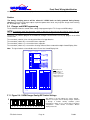
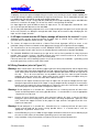
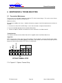
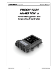
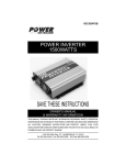
The ITC-Series system consists of a DC to AC true sine wave inverter, a 12-volt battery charger, an automatic
AC transfer switch, and a microprocessor based controller. An important feature of this system is the ITC-Series
Control/Display Unit user interface.
ITC-Series Inverter System
Fuse
+12 VDC
12 Volt
Battery
Control Display Panel
IN C OR P OR AT E D
Inverter
On/Off
Control/Relay
Board
Charger
On/Off
Overload
Power
Stage
Overload
Low
Battery
Bulk
Fault
Fault
Microprocessor
Control System
for Inverter/
Charger
SigRel
nalay
s
Relay Contol Output for AutoThrottle
Low Battery Indicator Contact
Optional Remote Switch
On/Off Switch
Transformer
Dead
Battery
Supply
CB In
120 Vrms Input for Charger
CB Out
AC Out 120 Vrms
GFCI
F 1 Figure 1.1-1 System Diagram
ITC-Series Inverter
Page 5
Owner’s Manual 8/07/03
G
= >?@AB @A CD E F
1.2
H
Front Panel Wiring Identification
System Features
Inverter
H
The inverter consists of a sine wave inverter that supplies power when AC loads are applied. Depended on
®
your model, the inverter develops 2100 or 3200 watts of continuous power. Using TruSine technology, a
very high quality sine wave is produced. Total harmonic distortion (THD) is less than 4.0 percent. The
inverter also has a three second surge rating of 6400 Watts.
Battery Charger with Automatic Power Management
A high efficiency, multi-stage battery charger, allows fully automatic charging of flooded and gel lead acid
battery banks. The efficient 0.85PF, compared to typical 0.59PF on triac type chargers, allows full charger
output from a 30-amp AC source. The system’s Bulk, Absorption, and Float charge cycle quickly charges
and maintains the battery bank. An Equalization charge cycle is provided for flooded lead acid battery
maintenance.
I
Automatic Power Management (APM) monitors the AC Input current and will reduce the battery charger
output as needed to keep the AC input current below the preset APM Limit.
GenStart/Auto-Throttle
I
The GenStart/Auto-Throttle feature provides a start/stop signal to control an automatic throttle module. The
start/stop signal consists of a contact closure to start the Auto-Throttle based on battery voltage of 12.3 VDC.
The GenStart/Auto-Throttle turns off when the battery charging current falling below 10 amps. Call Vanner
at 1-800-ACPOWER for technical assistance in selecting the proper auto-throttle kit to use for this
application.
Low Battery Contact
I
This contact allows remote monitoring of the Inverters battery status. The contact will closes when battery
voltage falls below 11 volts. This will alert the user to take appropriate measures to avoid shutdown of the
Inverter at 10.5VDC.
Remote Power Switch
This loop between Options Terminal 7 and 8 (left side of Options Terminal) allow remote control of the
system On/Off. Tying these two terminals together or optionally, tying the terminal 7 (Remote Switch) to
battery ground applies power to the unit.
J
Note: The Front Panel switch will always overrule the remote switch in terms of disabling the unit.
J
System Control
The ITC contains a System ON/OFF Switch located in the front of the ITC. This switch is used to turn the
control power ON and OFF. This power switch also has a break out loop for a series switch that can be
placed in a remote location from the unit (See Remote Power Switch above). A control microprocessor
provides a variety of protection interlocks, system fault detection/reporting/recovery, storage of system data
parameters, and high-speed data communications to the ITC Control/Display Unit. This Control/Display Unit
also has individual on/off switches for independent Inverter and Charger control. The ITC will protect itself in
the event of any overload, over temperature, high or low battery voltage condition.
ITC Control/Display Unit
The ITC Control/Display Unit is a user interface that is connected to the ITC Control Board via a 6-wire
communication bus. This Control/Display unit can be an integral part of the Inverter or can be removed and
mounted in a remote area to allowing remote system operation. Two of these units can talk to the System
Control Board one Unit would be configured as a Master, and the other as Slave. The configuration switches
on top of the Master allow programming of the Charger current, Automatic Power Management and battery
type settings.
NOTE: It should be noted that if the Control Display unit is taken out of the front of the unit, the cover plate
ITC-Series Inverter
Page 6
7/18/03
U
K LMNOP NO QR S T
Front Panel Wiring Identification
must be installed in it’s place to insure that debris does not enter the unit through the opening and to
maintain proper airflow through the unit.
1.3
Specifications
AC OUTPUT
Voltage (RMS)
Frequency
AC Waveform
Total Harmonic Distortion (THD)
Power Factor Allowed
Continuous Output Rating @ 25ºC
Phase to Neutral
Surge Capacity @ 25ºC (3 sec.)
DC INPUT:
Operating Range (12 Volt Nominal)
No Load, Inverter ON
No Load, Inverter OFF
Full power
INVERTER EFFICIENCY @ 12VDC
200 watts
500 watts
700 watts
1000 watts
1500 watts
2000 watts
2500 watts
3000 watts
3200 watts
AC INPUT
Voltage
Frequency
AC TRANSFER SWITCH
Power Rating
Transfer Time
BATTERY CHARGER
Charger Output Current maximum
AC Input Current maximum
SYSTEM
Ambient Operating Temperature
Cooling Exhaust Fan
Mounting
Dimensions (Bottom mount position)
Weight
ITC-Series Inverter
Model ITC12-2100
Model ITC12-3200
120 VAC
60 Hz ± 0.5%
Sine Wave
Less than 4.0% @ full power
-1 to 1
2100 watts (17.5 amps)
3200 watts (26.7 amps)
6400 watts
10.5 to 17 Volts
4 amps
0.30 amps
208 amps
350 amps
77%
88%
88%
88%
86%
84%
NA
NA
NA
81%
78%
77%
120 Volts nominal
60 Hz ± 12.5% (52.5 to 67.5)
30 amps @ 120 VAC
Less than 40 milliseconds
80 amps
30 amps (0.88PF @ rated output)
-40 to+40 V C (-40 to+104 V F)
Thermostatically controlled
Shelf or suspended
8 1/4”H x 18 7/16”W x 13 5/8”D
66 pounds
Page 7
Owner’s Manual 8/07/03
a
W XYZ[\ Z[ ]^ _ `
1.4
Front Panel Wiring Identification
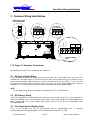
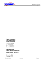
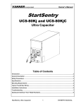
Component Identification/Location
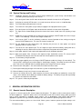
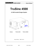
The Figures below show the location of the various components of the ITC system.
1
ITEM #
DESCRIPTION
1
BATTERY TERMINAL ACCESS
2
REMOTE CABLE INPUT
3
CONTROL/DISPLAY PANEL
4
INVERTER ON/OFF SWITCH
5
CHARGER ON/OFF SWITCH
6
SYSTEM ON/OFF SWITCH
7
AC INPUT BREAKER (CB-1)
8
AC OUTPUT BREAKER (CB-2)
9
GFCI BREAKER (CB-3)
10
AC INPUT CABLE ENTRY
11
BATTERY +
12
BATTERY -
13
GFCI OUTLET
14
AC OUTPUT CABLE ENTRY
15
OPTIONS CABLE ENTRY
16
CHASSIS GROUND
TOP VIEW
3
4
5
6
7
8
9
INCORPORATED
Inverter
On/Off
Charger
On/Off
Overload
Overload
Low
Battery
Bulk
Fault
Fault
FRONT VIEW
2
13
11
12
14
10
15
16
LEFT SIDE VIEW
RIGHT SIDE VIEW
F 2 Figure 1.4-1 Component Location
ITC-Series Inverter
Page 8
7/18/03
l
b cdefg ef hi j k
Front Panel Wiring Identification
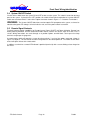
Configuration Switches Access
Configuration Switches
for Programming
On/Off Switch for Inverter
On/Off Switch for Charger
INCORPORATED
Inverter
On/Off
Charger
On/Off
Overload
Overload
Low Battery
Bulk
Fault
Fault
Note: Power Must be
Cycled to read a new
DIP Switch value
Equalize button access
Through Access hole.
Configuration Switches
Serial Communications
Connection
F 3 Figure 1.4-2 ITC Control/Display Unit
3
1
INCORPORATED
2
4
Inverter
On/Off
Charger
On/Off
Overload
Overload
Low Battery
Bulk
Fault
Fault
5
6
7
8
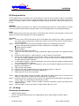
F 4 Figure 1.4-3 ITC Control/Display Unit Component Identification
ITEM
DESCRIPTION
Solid when on, flashes when enabled but not on
7
Inverter Indicator
Light
Inverter On/Off
Button
Charger Indicator
Light
Charger On/Off
Button
Overload Light
Low Battery/Bulk
Light
Fault Light
8
Equalize Button
1
2
3
4
5
6
ITC-Series Inverter
Enables/Disables Inverter Function
Solid when on, flashes when enabled but not on
Enables/Disables Charger Function
Dual Purpose – Indicates if Inverter or Charger is Overloaded
Dual Purpose – Indicates Low Battery in Inverter Mode – In charger mode, if on indicates that
Charger is in Bulk Mode and if in Equalize, this light flashes.
Dual Purpose – Indicates that a fault has occurred in the inverter or Charger – Could be a Over
Temperature shutdown, Low/High Battery Shutdown, Power Stage Fault, or Input AC fault
This is used to enable the equalization cycle on the battery during charging.
Page 9
Owner’s Manual 8/07/03
w
x
m nopqr pq st u v
Front Panel Wiring Identification
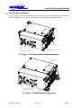
Versatile Mounting System
The mechanical system used for mounting the ITC-Series allows both shelf and under-counter mounting,
while still allowing access to user AC and control terminals through a removable front cover.
`
DC TERMINATIONS
POWER ON/OFF SWITCH
With Indicator
ACCESS PANEL REMOVABLE FROM
FRONT WHEN UNDER TABLE
MOUNTED.
DOCKED DISPLAY/CONTROL PANEL
F 5 Figure 1.4-4 Suspended Mounting Configuration
Access Cover To DC
Terminations
Mounting Feet shown in Benchtop
Mounting Configuration
F 6 Figure 1.4-5 Bench Mount Configuration
ITC-Series Inverter
Page 10
7/18/03
y z{|}~ |}
Front Panel Wiring Identification
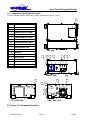
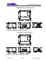
ITC DIMENSIONS FOR SUSPENDED MOUNTING
18
10 7/8
19 1/4
8 1/8
7 5/16
13 5/8
8 3/4
16 3/4
F 7 Figure 1.4-6 Suspended Dimensions in Inches
ITC DIMENSIONS FOR SHELF MOUNTING
18
10 7/8
19 1/4
7 5/16
8
13 5/8
16 3/4
F 8 Figure 1.4-7 Bottom Mount Dimensions in Inches
ITC-Series Inverter
Page 11
Owner’s Manual 8/07/03
Front Panel Wiring Identification
REMOTE MASTER AND
SLAVE CONNECTORS
P6
AC INPUT
HOT NEU GND
AC OUTPUT
HOT NEU GND
P14
P15
REMOTE LED
GND
REMOTE
SWITCH
P5
LOW BATT
AUTOTHROTTLE/
GENSTART
COM
N/O
N/O
COM
P3
OPTIONS TERMINAL
STRIP
F 9 Figure 1.4-4 Customer Terminations
ITC-Series Inverter
Page 12
7/18/03
Front Panel Wiring Identification
2 DESCRIPTION OF OPERATION
2.1
Inverter
The System ON/OFF Switch, located on the front panel, allows the user to turn the system power ON and OFF
and to reset the system after a fault.
The Charger ON/OFF and Inverter ON/OFF switches, located on the Control/Display Unit enable or disable the
Charger or Inverter Functions. The corresponding light next to Inverter/Charger switches will be steadily on when
the unit is in the Inverter or Charger mode. These Inverter and Charger lights will blink if the mode is not currently
on, but are enabled (Example: The Inverter light will blink when the Inverter is Enabled, the ITC is plugged into
the utility, and the Charger is Active).
The Inverter AC Output Circuit Breaker is a 1 pole, 30 amp breaker marked “CB-2” on the front unit. The CB-2
breaker protects the Inverter AC output and a second Breaker (CB-1) protects the Battery Charger AC input
against a severe overload. This CB-1 breaker also protects AC Pass through Power. If this CB-1 breaker trips
during charger operation, it must be reset.
Inverter Protective Interlocks
The Inverter operation is protected by a series of safety interlocks that protect against most failures such as
overloads, over-temperature conditions or other conditions where the unit may be asked to operate outside safe
battery voltages. These faults will trigger a display of the “Fault” and or “Overload” Lights on the Control/Display
panel and are listed below:
Low Battery
The inverter continually monitors battery voltage. If battery voltage falls below the Low
Battery Shutdown 10.5 VDC setpoint the inverter will shut OFF. Auto-restart will restart the
inverter after battery voltage rises above the Low Battery Warning 11 VDC setpoint (after 5
minutes).
High Battery
The inverter will shut OFF if battery voltage rises above the High Battery 17 VDC setpoint.
Over Temperature The inverter will shut OFF if internal temperature sensors detect a high temperature
condition that would damage the inverter.
Over Load
If a short circuit or an overload is applied to the inverter’s output the inverter will shut down.
Battery High
The unit has shut down due to the Battery voltage is above High Battery Shutdown setpoint
of 17 VDC.
Battery Low
Hardware Fault
Battery voltage is below Low Battery Warning setpoint and soon may reach Low Battery
Shutdown setpoint of 10.5 VDC.
Inverter AC output current is at the Maximum Current allowed and is presently in “Surge”.
The AC voltage will decrease if load increases. Overload Shutdown will occur if voltage goes
below 105VAC for 3 second.
Inverter has shut down due to overload. High AC load caused inverter output voltage to fall
below tolerance for three seconds.
Internal circuits failure or power brick high temperature will shut down system.
Overheat
The SCR plate or power brick overheating will cause the system to shutdown.
Current Limit
Overload
If the unit has faulted there are the two following options:
1. Auto-restart
After shutting down for any of the above fault conditions, the inverter will try to restart itself
every 5 minutes if Auto-Restart is Enabled and the fault condition no longer exists.
2. Manual restart
You can manually restart the system after the fault conditions are removed. Reset the
inverter by turning the System ON/OFF Switch OFF and then ON.
ITC-Series Inverter
Page 13
Owner’s Manual 8/07/03
¤
¡ ¢ £
2.2
Front Panel Wiring Identification
Battery Charger
The battery charger’s advanced design incorporates an automatic, multi-stage charger. This design enables the
unit to automatically charge batteries, which maintains the battery’s integrity and reduces the likelihood of
premature battery failure. The battery charger is designed to be used with lead-acid type batteries including
sealed and gel types, but not for nickel-cadmium (Ni-Cad) or nickel-iron types.
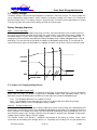
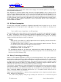
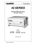
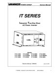
Battery Charging Sequence
Stage 1: Bulk Charge Stage
The charger always starts in the Bulk charge stage each time shore power becomes present and/or each time
the charger is turned ON. In the Bulk charge stage, the system charges at the ‘Bulk Charge Amps’ setpoint until
the battery voltage rises to the ‘Bulk Charge Voltage’ setpoint. Then the voltage is held at that setpoint until
charging current has fallen to 5 amps above the ‘Battery Absorption Amps’ setpoint (Absorption Amps = 50% of
Bulk Amps). This ends the Bulk Charge Stage and begins the Absorption Charge Stage. The charger will not
enter the Bulk Stage again until shore power is re-applied, or until the charger or the system is turned ON again.
VOLTAGE
TRIGGER POINT
FL
OA
T
EQ
(O UAL
PT
I
IO ZE
NA
L)
BU
LK
TIME
AB
SO
RP
TIO
N
CURRENT
F 10 Figure 2.2-1 Charging/Voltage Curves
Stage 2:
Absorption Charge Stage
The Absorption Charge Stage provides a controlled “overcharging” of the battery that is necessary to bring the
battery up to full charge. The battery is charged at the ‘Absorption Charge Amps’ (Absorption Amps = 50% of
Bulk Amps) until one of following three conditions occur that signals the end of the Absorption Stage;
Time: The Absorption Maximum Time setpoint is reached
Time: The Absorption Charge Stage time has reached ½ of the duration of the Bulk Charge Stage.
Voltage: Battery voltage reaches the ‘Absorption Voltage’ setpoint
Stage 2A Equalize Charge Cycle
When Equalize Mode is ENABLED (by inserting a paperclip or similar device through the Control/Display unit
Equalize hole), one Equalize Charge Cycle will follow the Absorption Charge Stage. The Equalize Cycle will last
for the ‘Equalize Time’ setpoint of 15 minutes. Equalize Mode will automatically switch to DISABLED at the end
of the Equalize Charge Cycle. During the Equalize Cycle the battery is charged at the ‘Absorption Charge Amps’
setpoint and the Equalize Voltage 15.5 VDC setpoint.
The Equalize Charge Cycle provides a deliberate overcharging of the battery to remove sulfate, which
accumulates on the battery plates through normal use. Equalizing returns battery cells to equal performance
ITC-Series Inverter
Page 14
7/18/03
¯
¥ ¦§¨©ª ¨© «¬ ®
Front Panel Wiring Identification
levels, which improves battery performance and extends battery life. Consult the battery manufacturer for their
recommendation regarding how often the Equalize Cycle should be performed.
CAUTION
Do not equalize sealed (valve regulated lead acid, AGM or gel) batteries! Consult battery manufacturer for
equalizing guidelines. Do not equalize more often than approximately once a month. Check battery fluids after
equalizing is complete, as gassing will occur. Use Equalize Mode only if batteries are in a well ventilated area!
Stage 3:
Float Charge Stage - Maintenance Mode
In the Float Stage the charging voltage is reduced to the ‘Float Charge Voltage’ setpoint and charging current is
limited to the ‘Absorption Charge Amps’ setpoint. The charger will remain in the Float Stage until shore power is
reapplied, or until the charger or system is turned OFF and then ON again.
Charging Setpoints
The ITC’s battery charger factory setpoints are for wet batteries. Do not use GEL type batteries without changing
the factory setpoints via the configuration switches.
CAUTION
Do not operate DC loads, such as DC lights, pumps, etc., during battery charging. The loads may cause
overcharging by preventing the charging stages from reaching their ‘trigger points’ or may cause the battery to
run down even though the charger is ON.
T 1 Figure 2.2-2 Battery Charger Factory Setpoints
Guideline
Factory Setpoint
(for Wet Battery)
Bulk Charge Volts
14.2 VDC
Bulk Charge Current
20% C Rate
80 Amps
Absorption Charge Volts
14.5 VDC
Absorption Charge Current
40 Amps
Absorption Maximum Time
10 Minutes
Float Charge Volts
13.2 VDC
Equalize Volts
Wet only
15.5 VDC
Equalize Maximum Time
Wet only
15 Minutes
Battery ‘C Rate’ is equal to battery Amp Hour capacity.
Factory setpoint for
Gel/AGM Battery
14.1 VDC
80 Amps
14.2 VDC
40 Amps
10 minutes
13.7 VDC
Not used
Not used
Automatic Power Management (APM)
A key feature of the battery charger operation is Automatic Power Management (APM). This feature monitors the
AC input current and will reduce the battery charger output as necessary to keep the AC input current under the
APM setpoint. The APM circuit will not limit power to the passthrough AC loads. If the passthrough AC loads
exceed 30 Amp, the battery charger output will be reduced to zero and the breaker may trip.
2.3
Gen Start/Auto-throttle
It should be noted that the Generator Start Operation is designed to minimize the generator run time, so at the
present set points there is no Absorption stage per se. Therefore, the batteries must be periodically conditioned
by leaving the generator on, or charging them with another system.
The Gen Start/Auto-throttle feature is designed for use in installations where a generator is used to provide AC
input power for battery charging. Alternately, these contacts are used to enable an Auto-throttle when the battery
voltage drops below the 11.0 VDC setpoint. The Gen Start/Auto-throttle feature provides a contact closure to
signal the generator to start when battery voltage falls below the ‘Gen Start Volts’ 11.0 VDC setpoint. The Gen
Start/Auto-throttle contacts open when bulk charging current fall below the ‘Gen Stop Amps’ 10 Amp DC
setpoint. The Bulk charging current is checked every 4 minutes, therefore the minimum generator ON time is 4
minutes. The contacts are NEC Class 2, rated 2 amps at 12 VDC.
It should be noted that the Gen Start/Auto-throttle contacts are shown in Figure 1.4-4 Customer Terminations,
ITC-Series Inverter
Page 15
Owner’s Manual 8/07/03
º
° ±²³´µ ³´ ¶· ¸ ¹
Front Panel Wiring Identification
and likewise a similar set of Normally Open Contacts are available to indicate a “Low Battery” condition.
Caution
The battery charging process will be affected if 12VDC loads are being powered during battery
charging. The increased charger output, required to power those loads, may keep the charger from reaching
the ‘Gen Stop Amps’ setpoint.
2.4
Charger and APM Programming
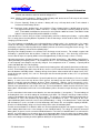
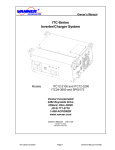
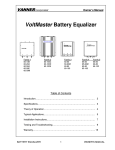
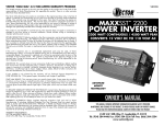
The chart below shows the control switch settings for programming the ITC Charger and APM settings.
NOTE: It should be noted that the power switch on the front of the unit must be cycled to read in the new
Control Switch settings into memory. The new values will not be recognized until this takes place.
The first 4 (1-4) switches program in the Maximum Charger Current and the next 4 (5-8) program in the APM
Current Limit.
The next switch (switch 9) is for selecting either Wet or Gel type batteries.
The next switch (switch 10) is reserved for future expansion.
The next switch (switch 11) is reserved for future expansion.
The next switch (switch 12) is reserved for selecting a Master/Slave remote with multiple Control/Display Units.
Note: The figure below is also available on the Rear of the Control/Display Unit.
DIP SWITCH
1
2
3
4
5
6
7
FUNCTION
SW POSITION
CHARGER
OUTPUT
CURRENT
SELECTION
ON
OFF
APM
CURRENT
SELECTION
ON
OFF
8
CHARGER
CURRENT
(AMPS)
5
10
16
21
26
32
37
42
48
53
58
64
69
75
80
9
BATTERY TYPE
GEL
WET
10
SPARE
ON
OFF
11
SPARE
ON
12
MASTER/SLAVE
DIP SWITCH
POSITION
1
2
3
4
|
|
|
O
|
|
O
|
|
|
O
O
|
O
|
|
|
O
|
O
|
O O
|
|
O O
O
O
|
|
|
O
|
|
O
O
|
O
|
O
|
O
O
O
O
|
|
O
O
|
O
O
O O
|
O
O O
O
OFF
MASTER
APM
CURRENT
(AMPS)
0
2
4
6
8
10
12
14
16
18
20
22
24
26
28
30
SLAVE
DIP SWITCH
POSITION
5
6
7
8
|
|
|
|
|
|
|
O
|
|
O
|
|
|
O O
|
O
|
|
|
O
|
O
|
O
O
|
|
O
O O
O
|
|
|
O
|
|
O
O
|
O
|
O
|
O O
O
O
|
|
O
O
|
O
O
O
O
|
O
O
O O
Note: After a new
switch setting is set,
the power switch
must be cycled on the
main unit for the new
setting to take effect.
| - ON
O - OFF
F 11 Figure 2.4-1 APM/Charger/Config DIP Switch Settings
0
1
1
2
3
4
ITC-Series Inverter
5
6
7
8
9
10 11 12
Page 16
The graphic to the left indicates the factory defaults.
Switches 1 through 4 show an 80-amp charger. Switches
5 through 8 indicate 30-amp automatic power
management. Switch 9 has selected Wet Cell battery
configuration.
Switch number 12 indicates “Master”
display/control unit.
7/18/03
Å
» ¼½¾¿À ¾¿ Á à Ä
Front Panel Wiring Identification
3 Customer Wiring Identification
REMOTE MASTER AND
SLAVE CONNECTORS
P6
AC INPUT
HOT NEU GND
AC OUTPUT
HOT NEU GND
P14
P15
REMOTE LED
REMOTE
SWITCH GND
GND
P5
LOW BATT
AUTOTHROTTLE/
GENSTART
COM
N/O
N/O
COM
P3
OPTIONS TERMINAL
STRIP
F 12 Figure 3-1 Customer Terminations
All field wiring enters the ITC housing through the side panels.
3.1
AC Input & Output Wiring
The AC wiring compartment is located on the front right side of the unit. A removable access cover covers this
compartment. Two cable clamps are installed for the AC input and AC output wiring. The removable access
cover can be removed by simply removing the screws on the front panel of the unit (ONLY!). There is no need
to remove screws from the top or sides of the unit to gain access to the AC wiring compartment. Inside the
compartment is a terminal strip for making AC input and AC output connections (P14 and P15).
NOTE
The AC output voltage and the required AC input voltage of the ITC is 120 VAC, 60Hz.
3.2
DC (Battery) Wiring
3.3
Front Panel Control/Display Outlet
A DC wiring compartment is located behind the wiring panel on the right side of the unit. The compartment
contains a removable access cover on the top of the inverter and two cable clamps for the battery positive and
battery negative cables. The inverter’s battery cable terminal studs are 5/16-18 and can accommodate Cable
sizes up to 250 MCM.
This is a RJ-11 (6-Wire) jack (P5) for communications with the Control/Display Unit.
Control/Display unit can be plugged into the P6 jack who would be configured as a slave.
ITC-Series Inverter
Page 17
A secondary
Owner’s Manual 8/07/03
Ð
Æ ÇÈÉÊË ÉÊ ÌÍ Î Ï
3.4
Front Panel Wiring Identification
System ON/OFF Switch
Use this rocker switch to turn the system ON and OFF and to reset the system. This switch is located on the front
panel of the system. If placed in the “OFF” position, this switch will override the operation of a remote ON/OFF
switch connected to terminals 7 and 8 of the Options connector shown in Figure 3-1 – Customer Terminations.
WARNING:
The System ON/OFF Switch does not interrupt the DC input power to the system, so it must be
noted that dangerous DC voltages still exist inside the unit, even if the power switch is turned off.
3.5
Remote Signal Contacts
Terminal Contacts provide capabilities for Remote Inverter Power ON/OFF and Power indication, Remote Low
Battery Warning indication, and Gen Start/Auto-Throttle control. Contacts are rated 2 amps at 12 volts, Class 2
circuits. Wiring connections are made through an 8 position Options terminal block. Screw pressure-clamp
terminals accept up to 14-gauge wire.
A remote power switch will control the system by tying terminals 7 and 8 of the options connector (shown in
Figure 3-1) together. This will actuate an internal relay that turns the control power on. The Power On/Off switch
on the front panel defeats this remote switch.
In addition, a terminal for a remote LED indicator is provided (terminal 6) with a current limiting resistor integral to
the circuit.
ITC-Series Inverter
Page 18
7/18/03
Û
Ñ ÒÓÔÕÖ ÔÕ ×Ø Ù Ú
Installation
4 INSTALLATION
Unpacking the Inverter
Inspect the shipping container and equipment for loose or damaged parts. If any damage is found, immediately
notify the freight carrier.
4.1
Basic Guidelines
The wiring of your inverter installation should conform to the National Electric Code (NEC) and any other state or
local codes in effect at the time of installation. These codes have been written for your protection and their
requirements should be followed.
Mounting
Locate a secure, dry, flat horizontal surface large enough to mount the inverter. The location should be as close
to the battery as possible without being in the same compartment and should provide adequate ventilation to
maintain room temperature while the inverter is operating. The location must allow unobstructed cooling airflow
at sides, rear, and bottom of the unit, and the location must be free from road spray, dripping water or other
moisture contamination. A recommended minimum clearance of 4 inches (102 mm) should be maintained on all
sides of the unit.
WARNING: Risk of fire or explosion. The inverter must not be mounted in fuel storage areas, battery
compartments, or other hazardous areas where potentially explosive gases may be present.
WARNING: It is important to utilize the included mounting brackets mounting. Mount the inverter in the
under cabinet method or bolted to a shelf. There must be a minimum of 5/8 inches below the unit, which
provides adequate airflow to cool the Inverter/Charger. If the unit is to be set on its base (in a shelf mount
configuration) and not bolted down, make certain that the mounting feet are bolted to the unit to provide the
adequate clearance as shown below.
INCORPORATED
Inverter
On/Off
Overload
Charger
On/Off
Overload
Low
Battery
Bulk
Fault
Fault
F 13 Figure 4.1-1 Shelf Mount Configuration
NOTE
The wiring of your inverter installation should conform to the National Electric Code (NEC) and any other state or
local codes in effect at the time of installation. Article 551 of the NEC requires any DC cable from a battery,
which measures longer than 18 inches along its length, be protected by a fuse. Other codes may require each
ungrounded output conductor from a storage battery, other than to the engine cranking motor, to have a
manually reset trip-free circuit breaker or fuse within 18 inches of the battery as measured along the conductor.
ITC-Series Inverter
Page 19
Owner’s Manual 8/07/03
æ
Ü ÝÞßàá ßà âã ä å
4.2
Installation
DC Wiring
Preliminary Considerations
1. BE AWARE that, as a large number of capacitors become charged upon completion of the DC circuit,
THERE WILL BE A LARGE SPARK when the last battery connection is made. The spark is normal and will
occur every time the batteries are connected.
2. The DC cables should be as short as possible. It is electrically more efficient to run the lower current AC
wiring longer distances than the DC cables. (See DC Cable Sizing Chart for proper size.)
3. Route the DC positive and negative cables as close together as possible, and use cable ties to keep them
together. This reduces some electromagnetic radiation that could interfere with some sensitive electronics.
3. On vehicle installations do not use the vehicle chassis as the DC negative conductor. Use a cable the same
size as the DC positive to go directly from the inverter to the battery negative.
4. Route the AC and DC power wiring separately, and with as much physical separation as possible, from low
voltage wiring such as audio and video signal wires.
5. DC power input cables that pass through steel or other ferrous metal walls need to pass through the same
hole. If two holes are required, cut a slot connecting the two holes to prevent a transformer effect.
6. Do not allow wire fragments or metal shavings to fall into the DC wiring compartment or to enter the inverter
in any way. Severe inverter damage will result which is not covered by the warranty.
7. Do not connect the inverter to the battery at this time. Final battery connections will be made after all
installation issues have been inspected.
8. WARNING: A poorly made high current connection may result in the risk of fire and personal injury.
9. WARNING: Be sure of the polarity of the DC input wiring. Reverse polarity may severely damage your
inverter and is not covered under warranty. Risk of fire or explosion of batteries may occur due to very high
currents.
10.A DC fuse is required to properly protect the inverter.
11.The table below shows the recommended minimum cable size which should be used. Wire sizing charts
published in the NEC may allow a greater amp capacity than we recommend. We have sized the cable for a
minimum voltage drop on the cable to maintain better performance of your inverter installation. The inverter’s
DC cable terminal lugs can accommodate cable sizes up to 250 MCM.
T 2 Table 4-1 DC Cable and Fuse Sizing Chart
DC Cable Size
Max. Distance
from Inverter to
Battery in Feet
Terminal Lug Amp Part
Number
Terminal Crimping Tool – Amp Part
Number
2100W (3200W)
250MCM Copper
Conductor
24 (16)
325703
4/0 Copper
Conductor
20 (13)
321271
Bussman Part
Number
Vanner Part
Number
2100W
Bussman ANL300
03645
3200W
Bussman ANL500
03646
Bussman 4164
03637
Fuse
Information
Fuse Holder
ITC-Series Inverter
Page 20
AMP DYNA-CRIMP Head - Part #69099
AMP DYNA-CRIMP Die - Part #46751-2
AMP DYNA-CRIMP Hydraulic Power Units Part #69120-1 or 314979-1
AMP Rota-Crimp Part# 600850 (2/0-4/0)
7/18/03
ñ
ç èéêëì êë íî ï ð
Installation
DC Wiring Installation
The DC input terminals are located in the rear right side of the unit and accessed from the top. The connections
are 5/16-18 brass studs that require a lugged connection and are to be tightened by a torque wrench. The
positive and negative cables enter the compartment through separate strain reliefs located at the right front of
the unit.
WARNING
Never make electrical connections "live". Make the connections to the inverter first, and the battery, last. Make
certain the ON/OFF control switch on front of inverter is in the OFF position before connecting to the battery.
NOTE
Severe damage to the inverter will result, which is not covered under warranty, if wire fragments or other metal
particles enter the inverter through the DC wiring compartment.
Procedure
Step 1: Turn the inverter OFF and disconnect all AC and DC power to the wiring harness. Make sure power to
the inverter wiring is disconnected. Verify that the inverter is turned OFF (the Inverter ON-OFF switch is
in the OFF position).
Step 2: Select a location for the unit. An ideal installation location has the following characteristics:
ò Close to the battery without being in the battery compartment (usually within six feet).
ò Protected from the weather.
ò Well ventilated.
Step 3: Connect the DC cables to the inverter:
A)
Remove the cover plate on the DC cable compartment exposing the positive and negative threaded
studs.
B)
Remove the two flat washers, split ring washers, and nuts from the threaded studs.
C) Put lugs (For the appropriate wire size called out in Table 4-1) on the ends of the Positive and Negative
DC Cable ends with the appropriate terminals. Be sure that all cable strands are completely in the lug
to avoid shorting to another conductor.
D) Insert the black, negative (-) cable end through the strain relief and onto the negative terminal threaded
stud, and tighten to 275 inch-pounds. .
E)
Insert the red, positive (+) cable end through the strain relief and onto the positive threaded stud, and
tighten to 275 inch-pounds.
F)
Tighten the two cable clamps.
G) Inspect the DC cable compartment to ensure that no foreign particles are present.
H) Replace the cover plate over the DC cable compartment.
I)
Repeat steps A, D, E, and H every 30 days.
Step 4:
Step 5:
Step 6:
Step 6:
4.3
Route DC input cables. Route the negative and positive DC input cables from the inverter to the
battery. If required, protect cables where they contact hard, sharp edges.
Install the in-line fuse. Install the in-line fuse in the red, positive DC input cable between the battery and
inverter, within 18 in. of the battery or DC wiring bus system.
Once all cables are double checked for proper connection and polarity, connect the battery to the
appropriate cable.
Verify Installation. Verify all connections are tight and the cables are secure.
AC Wiring
Preliminary Considerations
1. Output and Input Voltages
The ITC is designed to operate with an AC Output Voltage and AC Input Voltage of 120 VAC, 60Hz.
2. AC Wire Size
ITC-Series Inverter
Page 21
Owner’s Manual 8/07/03
ý
ó ôõö÷ø ö÷ ùú û ü
Installation
To properly size the AC input and output wiring the installer must consider the inverter output capability, the
inverter passthrough capability, and the battery charger input requirement. The AC input/output terminal strip
is a compression lug style that will accept up to 10 AWG copper wire.
Model ITC12-3200 – The 26.7 amp at 120-volt (3200-watt) inverter output capability requires #10 AWG wire
minimum is used for the AC output. The AC transfer switch is rated 30 amps at 120 volts.
Use input copper wire up to 10 AWG to suit the AC input source. The AC output wire should be the same
size as the AC input wire but not less than #10 AWG.
3. The AC Input and output wiring compartment is accessed by removing the front panel and is on the right side
of the unit. Field wires are brought in through two cable clamps to the terminal strips identifying the “AC
Input” and “AC Output” terminals.
4.
If AC Input is wired into the AC Output, damage will occur to the inverter! The power
distribution circuits must be designed to prevent AC power from an external source (shore power or a
generator) from feeding back into the inverter's AC output.
5. The inverter AC output must be wired to a Ground Fault Circuit Interrupter (GFCI) to ensure a safe
installation. Always maintain an isolated neutral downstream from the GFCI to prevent nuisance tripping.
6. The Circuit Breakers on the front panel are NOT BRANCH RATED! In all installations please follow all
national and regional electric codes and use the mandated branch rated breakers for power distribution.
7. The CHASSIS BONDING LUG located on the right of the unit has been provided for safety to prevent
possible shock hazards. Connect a #8 AWG minimum wire to this terminal and then to chassis of the
vehicle, the installation's grounding system, or to earth ground.
Failure to connect the chassis bonding lug to the chassis of the vehicle, the installation's grounding system,
or to earth ground may result in a lethal shock hazard.
AC Wiring Procedure (refer to Figure 3-1)
Warning: Make certain that the AC field wiring (upper right of the wiring compartment) and the Signal wiring
(at the lower right of the wiring compartment) are kept separate to avoid any problems or conflicts with
code. Make certain to route the Signal wires out of the provided port (lower most on the right side of
the unit). This is to insure that there are no problems that may arise from the poor insulation
properties of most signal level wire. Make certain that the auxiliary contact and option wiring are
routed below the barrier, and the AC Power Wires above the barrier.
Step 1:
Connect the AC output. Remove the front cover to expose the AC input and output terminal strips.
Identify the right terminals labeled “AC Output”. Insert the output field wires through the nearest (to the
board) strain relief into the AC wiring compartment. Tighten the strain relief. Connect the copper field
wires to the proper AC output terminals and tighten to 9 lb-in max.
Warning: Do not attempt to us a stranded wire. Stranded wire has a tendency to break off some of the
strands and will drop into the unit causing possible failures. If a stranded wire is used, the appropriate
“ring terminal” must be used.
Step 2:
Connect AC Input. Identify the terminal strip’s terminals labeled “AC Input”. Insert the field wires
through the (closest to the front panel) strain relief into the AC wiring compartment. Tighten the strain
relief. Connect the copper field wires to the proper AC input terminals and tighten to 9 lb-in max.
Replace the front cover.
Warning: Do not attempt to us a stranded wire. Stranded wire has a tendency to break off some of the
strands and will drop into the inverter causing possible failures.
appropriate “ring terminal” must be used.
If a stranded wire is used, the
Step 3:
Connect Bonding Lug. Use a 8 AWG or larger copper conductor to connect the chassis bonding lug to
the chassis of the vehicle, the installation’s grounding system, or to earth ground.
Step 4:
Verify Installation. Verify all connections are tight and secure for maximum performance.
ITC-Series Inverter
Page 22
7/18/03
þ ÿ 4.4
Installation
System Start-up and Testing
Step 1:
Completely install the ITC-Series Inverter/Charger following the system design considerations and
instructions provided previously in this manual.
Step 2:
Place the System Power On/Off switch located on the front of the inverter in the OFF position.
Step 3:
Verify that the external GFCI breaker is reset and connect an AC load, such as a 100-Watt light.
Step 4:
Turn ON the battery DC power to the inverter.
Step 5:
Turn ON the AC shore power (or generator) to supply the AC input power to the system
Step 6:
Place the System On/Off Power switch located on the front of the inverter to the ON position.
Step 7:
The Lights on the Control/Display Unit on the front of the inverter should come ON, by doing a lamp
test.
Step 8:
Disable the Charger Operation of the unit by pressing the Charger ON/OFF button once if the Charger
LIGHT is On or blinking. This turns the charger function OFF.
Step 9
If the Inverter LIGHT is not On or blinking, enable the Inverter Operation of the unit by pressing the
Inverter ON/OFF button once. This turns the Inverter function ON.
Step 10 The AC output test light should come ON, indicating the presence of shore power and correct
operation of the AC transfer switch.
Step 11: Turn off the AC shore power input. The AC output test light should immediately quickly blink once,
indicating the transfer switch transferred the test light from shore power to inverter power.
Step 12: At this point, apply AC loads up to rated output watts to verify full-power operation.
Step 13: Apply shore power. After a delay the AC output test light should blink and the ITC Inverter LIGHT
should blink indicating the transfer of the load from inverter power to shore power.
Step 14: Test the battery charger operation
A) With shore power applied, press the Charger ON/OFF button to enable the Charger (if not enabled). The
Charge LIGHT should come on and the batteries should begin charging. Remember to reduce the loads
on the unit since the APM will limit the available power to the charger based on its settings.
B) Disconnect the shore power – the unit should transfer back to Inverter mode.
C) Discharge the battery by placing the AC load on the system and operating the inverter.
D) When the battery charge level is low, the inverter will turn off.
E) Connect an ammeter to the DC cables between the inverter and the battery to monitor the current (DC
amps), and a voltmeter to the battery to monitor the battery voltage. The battery charger will step through
its sequence and stop in the float mode.
Step 15: The system is now ready for operation.
5
5.1
GENERAL INFORMATION SECTION
Generic Inverter Description
In general, an inverter converts DC electrical power into AC power. This power can be used to operate various
AC-driven appliances. Typical DC power sources include batteries that store electrical energy, power generated
from a vehicle alternator or renewable energy sources such as photovoltaic (solar) panels both with the
appropriate regulator or charge controller to bring the DC source within the operating range of the inverter.
The most common battery systems are 12 or 24 volt. Some systems, however, operate on higher voltages such
ITC-Series Inverter
Page 23
Owner’s Manual 8/07/03
General Information
as 32, 36, 48, or 120 volts. The most common inverter AC output power is 120 volts at a frequency of 60 Hz.
Some inverters, however, are designed to produce 240 volts, or both 120 and 240 volts at 60 Hz. Because
some countries use power of different voltage and frequency (e.g., 230 volts at 50 Hz), inverters are available to
conform to these requirements.
The three available inverter types are distinguished by the type of AC output waveform they produce. This
waveform affects the AC loads they operate. This section provides an overview of these inverter types, including
the advantages and disadvantages associated with using each type.
Sine Wave
Modified Sine Wave
Square Wave
Sine Wave Inverter
Sine wave inverters produce an AC output waveform like power produced by the electric utility companies and
rotating generators. The sine wave inverter’s waveform is characterized by the highest peak voltage and smooth
voltage transitions (no square wave components). Such inverters are the most costly of the three inverter types
because they contain additional electronics to produce the required waveform. A measure of the sine wave
quality is Total Harmonic Distortion (THD), and is expressed in a percentage. The lower the THD the higher the
quality of the sine wave power.
Modified Sine Wave Inverter
Modified sine wave inverters are sometimes called “quasi sine wave inverters” or “modified square wave
inverters.” Modified sine wave inverters generally cost more than square wave inverters because they contain
additional electronic circuitry to produce true RMS regulated AC output. Modified sine wave inverters have
higher AC peak voltages than square wave inverters, and automatically control the width of the AC output
waveform to regulate the output voltage (pulse-width modulation). The shape of the modified sine wave
inverter’s waveform includes a square wave component. It is stepped in such a way, however, to closely
approximate the true sine wave produced by the electric utility companies. Although this waveform has a higher
peak voltage than do square wave inverters, its peak voltage is not as high as a pure sine wave. Therefore, AC
loads containing power supplies might not always operate properly on the modified sine wave inverter.
Square Wave Inverter
The square wave inverter is a low cost device that produces a pure square wave AC power output. This AC
power can be an accurate 60 Hz frequency if it is crystal controlled. It does not have the necessary peak voltage
to properly operate many AC appliances that contain electronic power supplies (e.g., computers, TVs, and
VCRs). The square wave is appropriate when operating AC loads such as resistive heating devices.
5.2
Inverter Sizing
Output Power Rating - Power output is an important consideration when purchasing an inverter. Power is
defined as the rate that a device produces (or uses) electrical energy. This rate is measured in watts or kilowatts
(one kilowatt equals 1,000 watts), or sometimes in volt/amps. Volt/amps are roughly equal to watts and are
obtained by multiplying volts times current produced or used by a device
To properly determine an inverter size (in watts) for your application decide which AC loads you plan to operate.
Inverter size is the sum of the wattages of the AC loads that you wish to run at the same time, plus a safety factor
of 10 to 20 percent.
Continuous Output Power - Continuous power is defined as the AC power in watts (or volt/amps) that an inverter
can produce on a continuous basis at a given temperature.
Surge Output Power - Inverter power can also be rated in terms of surge power. Surge power is the short term
duration of AC power that the inverter can produce. It is often specified as the watts (or volt/amps) that can
operate a resistive load for two or three seconds. Sometimes this is specified in AC amps because the inverter
ITC-Series Inverter
Page 24
7/18/03
"
!
General Information
may allow output voltage to drop (which would reduce wattage). Like continuous power, the surge rating is
affected by ambient temperature.
Note - Regardless of an inverter’s power ratings, an inverter’s AC output capability is only as strong as the DC
source. To achieve optimum performance, an inverter must be installed with properly sized cable and have an
ample DC supply. Recommended cable sizes are listed in the DC Cable and Fuse Chart (Section 4.2). The
following sections in this manual will cover the basic information required to properly size the inverter battery and
the vehicle alternator. Keep in mind that if information in this manual directly conflicts with instructions from a
specific battery or other equipment manufacturer, Vanner recommends that the other manufacturer's
recommendations be followed.
5.3
DC Power Consumption
An inverter takes in DC power, and produces AC power to operate AC loads. In general, we can see a direct
relationship between DC input power and AC output power. This allows us to establish the following rule of
thumb:
For 12 volt DC inverters: Output Watts # 10 = DC Input Amps.
This rule of thumb can be used to estimate the minimum alternator size required for your application. It may also
be used in calculating the minimum size battery required when operating from an alternator and battery
combination; a photovoltaic panel and battery combination; or when operating from battery alone. The following
examples should help to clarify the use of this rule of thumb.
Example
What is the DC current draw of a 12-volt DC input inverter when it is operating a vacuum cleaner with a
nameplate rating of 6 amps at 120 volts AC?
The appliance rating is given in amperes, so we must first calculate the power it consumes. Then the
rule of thumb can be used to find the DC input current of the inverter.
Output power = 120 volts x 6 amps = 720 watts, and
DC input current = 720 # 10 = 72 amps DC.
This information to estimate the DC input current requirement for an inverter will allow you to size an
alternator or charging system to supply an inverter for continuous operation. This rule of thumb will be used
later in the discussions on battery sizing.
5.4
Battery Terminology and Ratings
Batteries used for automotive applications generally are lead-acid storage batteries. They can be separated into
two categories according to their use: engine cranking batteries and deep cycle batteries. The engine cranking
battery is specifically designed to supply hundreds of amps for a short period of time to start an engine. Cranking
an engine usually uses a small portion of the battery's total capacity and once the engine is running, the engine’s
alternator quickly recharges the battery. The deep cycle battery is specifically designed to deliver current for
extended periods of time and can be almost totally discharged before recharging.
The "deep cycle" lead-acid battery is designed to withstand the deep discharge/recharge cycling that is typical of
most inverter installations. These batteries are available in the "maintenance free" style where the electrolyte
does not need to be checked or replenished and they also are available in the gelled electrolyte style or "Gel
Cells". Deep cycle batteries are generally advertised for use in recreational vehicles or boats and are
sometimes referred to as RV or marine batteries.
Battery Council International (BCI) is a voluntary industry organization that has helped to standardize battery
ratings. Ratings in use at this date are:
CCA (Cold Cranking Amperes): Rating in amps a battery cold soaked at 0°F or –20°F will carry for 30
ITC-Series Inverter
Page 25
Owner’s Manual 8/07/03
.
$ %&'() '( *+ , -
General Information
seconds and maintain a minimum terminal voltage of 7.2.
MCA (Marine Cranking Amperes): Rating in amps a battery cold soaked at 30°F will carry for 30 seconds
and maintain a minimum terminal voltage of 7.2.
RC (Reserve Capacity): Rating in minutes a battery will carry a 25-amp load at 80°F and maintain a
minimum terminal voltage of 10.5.
AH (Amp Hour): At the “20 Hour Rate”, also called the C Rate, a battery having a 100 AH rating must carry
a 5 amp load for 20 hours (100AH ÷ 20 hours = 5 amps) and maintain a terminal voltage of 10.5 at
80°F. (Two 100AH 12volt batteries connected in series provides 100AH at 24 volts. Two 100 AH 12volt
batteries connected in parallel provides 200 AH at 12 volts.).
CCA and MCA are used for sizing an engine cranking battery and have no bearing on a battery's cycling ability.
RC is a rating given to cranking batteries to provide an idea of how long a vehicle could be driven if the vehicle
charging system were to fail.
The most important and probably least understood battery capacity rating is the ampere-hour. One simple
reason the AH rating is misunderstood is that a battery rated at 100 AH cannot always deliver 100 AH. The
underlying reason is the efficiency with which the battery converts its chemical energy into electric energy. The
AH capacity of a battery is affected in the following ways:
Discharge rate: A battery becomes less efficient as the discharge current increases. For example, a typical 100
AH battery is specified to be able to deliver 5 amps for a period of 20 hours. If the discharge current were
increased to 25 amps, the capacity will be reduced to approximately 75 AH (25 amps x 3 hours = 75 AH).
Operating temperature: A battery becomes less efficient at lower temperatures. Most battery manufacturers
specify the battery AH capacity at 80° F. At a temperature of 32° F, the same battery will have only about 65% of
its rated capacity even though it may be fully charged. At a temperature of 0° F, a battery's capacity will be
reduced to about 40% of its rated capacity.
Battery age: As a battery is used, the active material on the battery plates will gradually deteriorate and become
useless. As the battery gets older, there will be less and less useful material left on the plates and the operating
time will become noticeably shorter. A battery will age faster (loose active material from its plates faster) if it is
deeply discharged regularly, if it is left in a discharged state for extended periods of time, or if it is repeatedly
overcharged.
Series and/or Parallel Connected Batteries: Up to this point we have spoken of the battery as if it were a single
battery. In some cases this may be true, but in general, the battery may be made up of several individual
batteries electrically connected together to form a "Bank" of batteries. Batteries can be connected in series,
parallel, or a combination of series and parallel as long as all of the batteries in the bank are of equal ratings, are
from the same manufacturer, and are the same age. Old and new batteries should never be mixed in the same
battery bank. Mixed batteries will result in accelerated battery failure due to the unequal discharge and recharge
rates.
A series connection is where two or more batteries are connected positive (+) to negative (-). The total voltage of
the battery bank is the sum of the voltage of each battery in the bank. For example, most large custom coaches
require a 24-volt battery to crank the large diesel engine. The 24 volts is usually provided by connecting two 12
volt batteries in series, and sometimes by connecting four 6 volt batteries in series. The ratings of the series
connected battery bank remain the same as the individual battery's rating. If the battery bank is made up of two
8D size batteries in series, each with a CCA of 1050 amps, 425 minutes RC, and amp-hour capacity of 200 AH,
then these individual battery ratings are also the ratings of the entire 24 volt battery bank.
Parallel connected batteries are batteries which are connected positive to positive and negative to negative. They
form a battery bank that has the same voltage as each individual battery. The ratings of a parallel connected
battery bank, in general, are the sum of the individual batteries. For instance, if two 8D batteries are connected in
parallel, and each battery has the ratings given in the paragraph above, then the ratings for the battery bank
become 2100 CCA, 900 minutes RC, and approximately 400 amp-hours. Parallel connected batteries should be
of the same voltage and rating to achieve optimum battery life and performance.
ITC-Series Inverter
Page 26
7/18/03
9
/ 01234 23 56 7 8
5.5
General Information
Sizing the Inverter Battery
Sizing a battery system for an inverter application can be a very tedious task if all the different variables, such as
discharge rate, depth of discharge, and operating lifetime are included in the calculations. To simplify these
calculations and get a reasonably correct battery size, we will assume:
1) A 50% depth of discharge for the purpose of obtaining a reasonable life time for a reasonable battery
system cost
2) There is no charge current into the battery system
3) The batteries are in a fully charged state at the beginning of the discharge cycle
4) The DC current draw from the battery does not exceed 1/3 the C rate for any length of time.
Follow the steps listed below to find the AH capacity required for your application.
Step 1:
Make a list of each appliance, its power requirement in watts, and the amount of time in hours it will be
operating between charging cycles. Note: If the appliance is rated in amperes (amps) instead of watts,
multiply the amps by the voltage (120 or 240) to get watts.
Step 2:
Calculate the watt-hours required for each appliance by multiplying the power requirement by the
operating time of that appliance.
Step 3:
Calculate the total watt-hours needed by adding together the watt-hours of each appliance.
Step 4:
Find the amp-hours consumed by dividing the total watt-hours found in step 3 by 10 for 12 volt DC
systems or by 20 for 24 volt DC systems.
Step 5:
Multiply the amp-hours consumed by 2 (for 50% depth of discharge) to get the battery amp-hour
capacity desired.
Example 1:
Follow Steps 1 through 3 (above)
Appliance
TV, VCR, Stereo
Small Refrigerator
Microwave
TOTALS
Power Rating
225 watts
300
800
Operating Time
2.5 hours
3.8
0.3
Watt-Hours Consumed
563 watt-hours
1,140
240
1,943 watt-hours
Step 4:
Amp-hours consumed = 1943 watt-hours ÷ 20 = 97.15 amp-hours for 24 a volt system.
Step 5:
The minimum battery size for this application is 2 x 97.15 = 194.3 amp-hours.
5.6
Battery and Charging System Considerations
The Battery and DC Charging System is a very important part of your inverter installation. The Battery System is
responsible for supplying all of the DC power required by the inverter. The system normally consists of the
primary charger (engine alternator or photovoltaic array), a secondary charger, if used, the battery, and other
equipment which may be used such as battery isolator diodes. The complexity of the system depends on the
way the inverter is used. In some cases, such as utility or service vehicles, the system may be as simple as the
engine alternator and the cranking battery that also powers the inverter. In most cases, additional equipment is
needed to provide additional DC power and/or protection. These systems can be grouped into two categories,
the single battery and the dual battery systems.
In the single battery system, there is one battery, which is shared for starting the engine and operating the
inverter. This is a common practice in a service vehicle where the engine runs all the time and allows the
alternator to provide continuous charging for the battery. In this case, the inverter can be connected directly to
the engine cranking battery. The most important detail of this system is the alternator output rating. The
continuous output of the alternator must be at least as much as the total DC current draw on the system. The
ITC-Series Inverter
Page 27
Owner’s Manual 8/07/03
D
: ;<=>? => @A B C
General Information
total DC current draw must include the inverter, warning lights, radios, engine controls, and any other device
connected to the DC system. Care should be used when operating this type of system while the engine is shut
off. The inverter will shut itself OFF for low battery but most other DC loads will not. The vehicle battery may be
also drained too low to restart the engine.
The dual battery system uses two separate batteries, one for starting the engine and operating the vehicle's
systems, and one for operating the inverter. The two batteries are usually referred to as the "cranking battery"
and the "house or auxiliary battery" respectively. The two separate batteries are usually charged from the same
source, the engine alternator, but are separated by a device called a battery isolator. The battery isolator allows
DC current to flow from the alternator into each battery, but blocks current from flowing from one battery to the
other. This is required to protect the cranking battery in recreation vehicles, boats and other vehicles where the
inverter needs to be operated when the engine (therefore the alternator) is not running.
5.7
Battery Charging Guidelines
CAUTION
The following information on battery charger setup adjustments should be used as guidelines only. Vanner
strongly recommends that you contact the manufacturer of your batteries to obtain the specific charging
setup values for the type and model of battery you are using. This is because battery charging parameters
such as bulk, absorption, float and equalize voltages vary from one manufacturer to another, and that gel
cell batteries have different parameters than wet lead acid batteries. An improperly adjusted battery charger
may cause damage to your batteries!
The maximum charging current for a battery is usually equal to 20% of the battery's Amp hour capacity (“C
Rating”) for lead acid batteries, and 50% of the battery's C for gel cell batteries. The C rate is numerically equal
to the amp-hour capacity for the battery. For example, a 280 amp-hour battery has a C rate of 280 amps, and
the maximum charge rate would be 56 amps DC. (Note that this is not the same as the battery's Cold Cranking
Amp rating.) It is important to also take into consideration that if two batteries are connected in parallel, their
amp-hours add, while batteries that are connected in series have the same amp hours as a single battery since
they are simply stacked for more voltage. Remember, paralleled = more current; stacked = more voltage.
ITC-Series Inverter
Page 28
7/18/03
O
E FGHIJ HI KL M N
General Information
6 MAINTENANCE & TROUBLESHOOTING
6.1
Preventative Maintenance
There are no user serviceable components inside the ITC-Series Inverter/charger. For service refer to Vanner
Incorporated or other qualified service personnel.
Maintenance Items:
For continued reliability and safety, a monthly maintenance program should be implemented to include the
following:
1. Check to insure that all AC and DC wiring is secure and connections are tight and corrosion free.
2. Check air ventilation openings for dust and other obstructions.
3. Examine receptacle, indicators and switches for cracks and breaks in insulation material.
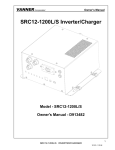
Trouble Shooting:
The Unit does not come on when Shore Power or DC is applied and the front Power Switch is on.
Suggestion:
REMOTE LED
REMOTE
SWITCH
GND
Make certain that the remote switch connected to Options Terminal Strip P3 -terminals (Remote Power Switch
P3-7– To Ground P3-8) is functioning properly. If the switch is not installed, make certain that a jumper is present
between the two left most terminals (P3-7 and 8) as shown below.
LOW BATT
AUTOTHROTTLE/
GENSTART
COM
N/O
N/O
COM
P3
OPTIONS TERMINAL STRIP
F 14 Figure 6.1-1 Options Terminal Strip
ITC-Series Inverter
Page 29
Owner’s Manual 8/07/03
Z
P QRSTU ST VW X Y
ITC-Series System
Vanner Incorporated
4282 Reynolds Drive
Hilliard, Ohio 43026
1-800-AC POWER
(1-800-227-6937)
Tel: 614-771-2718
Fax: 614-771-4904
www.vanner.com
e-mail: pwrsales@vanner.com
Manual Number D911149-A
Printed in USA
Copyright 2003
ITC-Series Inverter
Page 30
7/18/03