1
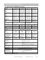
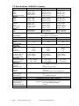
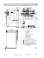
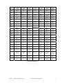
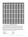
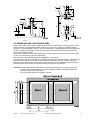
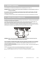
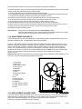
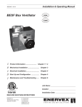
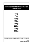
1. TABLE OF CONTENTS
1. TABLE OF CONTENTS.................................................................................................... 2
2. IMPORTANT SAFETY INSTRUCTIONS......................................................................... 2
3. TECHNICAL INFORMATION ........................................................................................... 4
3.1. SPECIFICATIONS 18/25/30/40 LB CAPACITY....................................................................................4
3.2. SPECIFICATIONS 50/60/80 LB CAPACITY.........................................................................................5
4. DIMENSIONS AND COMPONETS OF THE MACHINE .................................................. 6
5. HANDLING, TRANSPORT, STORAGE, UNPACKING ................................................... 8
6. FOUNDATION................................................................................................................... 8
6.1. GENERAL .........................................................................................................................................8
6.2. PREPARING FOUNDATION BASE...................................................................................................9
6.3. DIMENSIONS FOR FOUNDATION BASE.........................................................................................9
6.4. DIMENSIONS AND POSITIONING OF THE ACHORING ...............................................................10
6.5. DIMENSIONS AND POSITIONING RISERS ...................................................................................11
7. HOW TO INSTALL A WASHER..................................................................................... 12
7.1. MFR WASHER OR RISER INSTALLATION ON A CONCRETE PAD. ............................................12
7.2. MFR WASHER INSTALLATION ON A STEEL BASE (RISER) .......................................................12
7.3. SECURELY FASTEN THE WASHER..............................................................................................12
8. ELECTRICAL .................................................................................................................. 13
8.1. ELECTRICAL REQUIREMENTS .....................................................................................................13
8.2. ELECTRICAL CONNECTION..........................................................................................................13
8.3. LOAD ON ELECTRICAL SUPPLY NETWORK ...............................................................................14
9. WATER CONNECTION .................................................................................................. 15
10. WATER DRAIN CONNECTION.................................................................................... 15
11. AIRVENT OPENING ..................................................................................................... 16
12. LIQUID SOAPS CONNECTION ................................................................................... 16
13. MAINTENANCE AND ADJUSTMENTS ....................................................................... 17
13.1. DAILY ............................................................................................................................................17
13.2. EVERY SIX MONTHS ...................................................................................................................17
13.3. ADJUSTMENT OF DOOR SEAL PRESSURE ..............................................................................17
13.4. ADJUSTMENT GEAR BELTS .......................................................................................................18
13.5. REPLACEMENT WASHER FUSES ..............................................................................................18
13.6. ERROR INDICATION SHOWN ON DISPLAY ...............................................................................19
14. PUTTING THE MACHINE OUT OF SERVICE ............................................................. 19
14.1. DISASSEMBLY .............................................................................................................................19
15. LIST OF RECOMMENDED SPARE PARTS ................................................................ 20
516828
PUBLICATION DATE Nov 05
INSTALLATION INSTRUCTIONS
1
1. TABLE OF CONTENTS
2. IMPORTANT SAFETY INSTRUCTIONS
WARNING - Read the IMPORTANT SAFETY INSTRUCTIONS in this manual carefully before
operating the washer. Improper use of the washer may cause risk of fire, electrical shock
or serious body injuries or death as well as serious damage to the washer.
WARNING - Failure to comply with the instructions in this manual may lead to incorrect
use of the washer, and may result in risk of fire, bodily injuries or death and/or damage to
the laundry and/or the washer. Save these instructions for later use
♦ This English version is the original version of this manual. The instructions for the washer extractor are only complete
with the programming and user manual.
♦ The washer extractor is designed for fabrics washing only, other objects can damage the machine and can cause
damage or injuries.
♦ The manufacturer is not responsible for the damage to the fabrics that are washed by an inappropriate washing
method.
♦ Always follow the instructions and/or warnings that are stated on the fabrics, washing products or cleaning products
mentioned by the manufacturer.
♦ The washer must be set up in accordance with the instructions. All drain, inlet, electrical connections, ventilation,
groundings and other connections must be done in according to the installation manual, in compliance with the local
standards done by qualified technicians with proper authorization. The valid standards for connecting to the local
power network must be followed.
In the standard execution, the washer may not be suitable for connecting to an IT supply system. Contact your
commercial distributor for assistance.
♦ Never install this washer on any level (or floor) but the ground level. There should never be a floor (such as a
basement) located directly under the washer.
♦ The washer should always be tested before use.
♦ If the machine is used for special applications follow the instructions and warning to avoid person injury.
♦ Keep the washer surface and the area around clean and clear of combustible or flammable products.
♦ Do not wash articles that have been previously cleaned in, wash in soaked in, or spotted with gasoline, dry-cleaning
solvents, or other flammable or explosive substances as they give off vapors that could ignite or explode.
♦ Do not add gasoline, dry-cleaning solvents, or other flammable or explosive substances to the wash water. These
substances give off vapors that could ignite or explode.
♦ Under certain conditions, hydrogen gas may be created in the hot water system that has not been used for two or
more weeks. HYDROGEN GAS IS EXPLOSIVE. If the hot water system has not been used for such period open all
hot water taps and let the water run out for few minutes. This will release any accumulated gas. As this gas is
flammable, do not smoke or use open flames during this time.
♦ Always strictly comply with the instructions that are written on the laundry chemicals-, laundry aids-, dry-cleaning
solvents- and disinfectants packaging. Keep these agents out of the reach of children, preferably in a locked cabinet.
♦ Do not tamper the washer-extractor controls and do not bypass the safety instructions and the warnings.
♦ Do not remove warning signs placed on the machine. Observe signs and labels to avoid personal injuries.
♦ Do not put some part on the soap dispenser lid to hold it open by filling or when the machine operates.
♦ Do not open the soap dispenser lid after the machine is started. The discharge or splashing of hazardous liquid can
cause serious scalding and burning.
♦ Do not operate the washer when parts are broken or missing or when covers are open. The machine shall not be
operated until the fixed guards are put correctly in place.
♦ The washer is not designed for work which may create an explosive atmosphere inside the machine and will not be
used for this purpose.
♦ The washer must not be stored or exposed to the weather, extreme low or high temperature and humidity levels. Do
not hose down the washer. NEVER allow the washer to get wet.
♦ Check the functioning of the door lock mechanism on regular base. NEVER bypass the doorlock mechanism.
♦ Disconnect the power and water supply before cleaning, servicing or if the washer is not used for certain period.
♦ Out of the venting at the back of the washer can escape warm vapor or and hot air. Do not cover the vent but protect
it sufficiently. It serves air gap and as a vapor outlet to prevent pressure building in the washer.
2
INSTALLATION INSTRUCTIONS
PUBLICATION DATE Nov 05
516828
♦ Do not repair or replace any part of the washer or attempt any servicing unless specifically recommended in the
service manual or published user-repair instructions that you understand and have the skills to carry out. Only
qualified service personnel may open the washer to carry out servicing.
♦ Information contained in this manual is intended for use by a qualified service technician familiar with proper and safe
procedures to be followed when repairing an electrical appliance. All tests and repairs should be performed by a
qualified service technician equipped with proper tools and measuring devices. All component replacements should
be made by a qualified service technician using only factory approved replacement parts.
♦ Improper assembly or adjustment may occur if service or repair is attempted by persons other then qualified service
technicians or if parts other then approved replacement parts are used. Improper assembly or adjustment can create
hazardous conditions.
♦ There can be a risk of injury or electrical shock while performing services or repairs. Injury or electrical shock can be
serious or even fatal. Consequently, extreme caution should be taken while performing voltage checks on individual
components or a product. PLEASE NOTE: Except as necessary to perform a particular in servicing a product, the
electrical power supply should ALWAYS be disconnected when servicing a product.
♦ All industrial (OPL - On Premise Laundry) washers are designed for use in Laundry with professionally trained
attendants.
♦ The manufacturer reserves the right to change the manuals without previous notice.
♦ Before the appliance is removed from service or discarded, remove the door.
♦ Follow all valid basic safety rules and laws.
♦ If a problem should arise, contact your dealer for assistance.
!
WARNING -- CAUTION
In order to minimize the risk of fire, electrical shock and injury, THIS WASHER MUST BE PROPERLY
GROUNDED. Never plug in or direct-wire an appliance unless it is properly grounded in accordance
with all local and national codes.
If more machinery in the same location, mutual grounding must be applied where possible.
!
WARNING -- CAUTION
The washer is a rigid-mount model, it MUST be secured mounted to a NON-COMBUSTIBLE
foundation or adequate floor structure.
NEVER install the washer on an upper floor or over a basement without a load support designed by a
structural engineer. It is required the installation be on a concrete foundation.
Metal reinforced wood floors are NOT allowed due to the risk of fire and excessive vibrations.
! WARNING
Although the washer may be in the “off” position, there is still electrical power to the switch supply
terminals.
! WARNING
When power supply has been switched off wait for at least 10 minutes before starting inspection or
servicing the machine. Some parts carry’s for a longer time voltage.
! WARNING
Never permit children to play in or around the washer at any time. Never permit children to operate the
washer. Close supervision of children is necessary when the appliance is used near children.
! WARNING
Do not open door until cylinder remains stopped and water has been drained completely.
If the door safety lock does not work, do not use washer until the door lock mechanism is repaired.
! CAUTION!
The instructions in this manual cannot account for every possible dangerous situation. It is up to the
user to take proper care when operating the washer.
! CAUTION!
Safety labels appear at crucial locations on the machine. Failure to maintain legible safety labels could
result in injury to the operator or service technician.
! CAUTION!
If the installed machines operate with coin, token or similar operation, then the owner-installer must
provide a remote-located emergency stop device. This device must be placed in such a way that it is
easy and safely accessible for the users. The emergency stop device takes care that at least the
control circuit of the washer extractors is interrupted.
! CAUTION!
Any Water Leaks Must Be Repaired Immediately
516828
PUBLICATION DATE Nov 05
INSTALLATION INSTRUCTIONS
3
3. TECHNICAL INFORMATION
3.1. Specifications 18/25/30/40 Lb Capacity
Capacity:
Packing:
Width
Depth
Height
Transportation Volume
Machine:
Width
Depth
Height
Inner drum:
Diameter
Depth
Drum Volume
Door Opening
Weight
Net
Gross
Power Supply
Supply deviations
Nominal motor output
Current (Steady speed)
Supply Protection
Device
7 kg / 18 lb
10 kg / 25lb
13 kg / 30 lb
18 kg / 40 lb
carton box
700 mm / 27.6"
730 mm / 28.7"
1180 mm/ 46.5"
3
3
0.6m / 21.2 ft
carton box
700 mm / 27.6“
990 mm / 38.98“
1305 mm / 51.38"
3
3
0.9m / 31.8 ft
carton box
810 mm / 31.9”
970 mm / 38.19”
1395 mm / 54.92”
3
3
1.1m / 38.85 ft
carton box
935 mm / 36.8''
955 mm / 37.6''
1530 mm / 60.24''
3
3
1.37m / 48.4 ft
660 mm / 26“
710 mm / 28"
1045 mm / 41.1"
660 mm / 26“
865 mm / 34"
1140 mm / 44.9“
750 mm / 29.5”
820 mm / 32.3”
1225 mm / 48.2”
855 mm / 33.7''
895 mm / 35.2''
1315 mm / 51.8''
530 mm / 21“
330 mm / 13“
73 dm3 / 19.3 gal
290 mm / 11.4“
530 mm / 21“
420 mm / 16.5“
95 dm3 / 25 gal
290 mm / 11.4“
650 mm / 25.6”
395 mm / 15.6”
131 dm3 / 34.6gal
410 mm / 16.1''
700 mm / 27.6”
470 mm / 18.5''
181 dm3 / 47.8gal
410 mm / 16.1''
160 kg / 353 lbs
205 kg / 452 lbs
170 kg / 375 lbs
235 kg / 518 lbs
1x120V 60Hz
±10%, with max 1% of the frequency
600 W
5A
600 W
9A
10A
10A
285 Kg / 627 lbs
247 kg / 545 lbs
300 Kg / 660 lbs
262 kg / 578 lbs
1x208 / 240V 60Hz
3x208 / 240V 60Hz
±10%, with max. 1% of the frequency
0.75 kW
4.5A
15A
1.5kW
5A
15A
Motor Overload
electronic protection by the frequency inverter
Protection
Cylinder RPM
45 rpm
44 rpm
48 rpm
Wash
48 rpm
525 rpm
505 rpm
Spin max.
580 rpm
580 rpm
100
100
G-Factor max.
100
100
Floor Data
3.1kN / 675 lbs
Ref. Static Floor Load
1.7kN / 370 lbs
12.1kN / 474 lbs
2.6 kN / 577 lbs
8.9 kN / 1994 lbs
Max. dynamic load
3.6 kN / 801lbs
4.5 kN / 1020 lbs
6.5 kN / 1450 lbs
Freq. of dynamic load
8.75 Hz
8.42 Hz
9.67 Hz
9.67 Hz
Water Usage
*
*
*
*
Average water Usage
65 l / 17 gal
90 l / 24 gal
115 l / 30 gal
160 l / 43 gal
Average Hot water
15 l / 4 gal
23 l / 6 gal
30 l / 8 gal
42 l / 11gal
Water Inlets:
Cold and hot water connection
water pressure
0.1 - 0.8 MPa / 14.5 - 116 PSI
water inlet
3/4“
Water temp. max.
hot water max 90°C-194°F
Water Drain System
Gravity
dimension
76 mm / 3“
capacity
By free drain 145 l/min / 38.3 US gallons/min
Steam heating:
Optional
steam connection
1/2“
steam pressure
0.3 - 0.7 MPa / 45-100 PSI
Liquid soap signals
8 (see electrical scheme)
Soap Dispenser
3 compartments : Pre-wash -- Wash -- Last Rinse
Handling Conditions
Ambient temperature
Storage: -25°C to +55°C; Operating: 1°C to +35°C
relative humidity
30% ÷ 95% without condensation
height above sea level:
to 1000 m
Average noise level
66 dB (A)
* Depends on program and hot water temperature
4
INSTALLATION INSTRUCTIONS
PUBLICATION DATE Nov 05
516828
3.2. Specifications 50/60/80 Lb Capacity
Capacity:
Packing:
Width
Depth
Height
Transportation Volume
Machine:
Width
Depth
Height
Inner drum:
Diameter
Depth
Drum Volume
Door Opening
Weight
Net
Gross
Power Supply
27 kg / 60lb
35 kg / 80 lb
carton box
935 mm / 36.8"
1050 mm / 41.3"
1530 mm / 60.24"
3
3
1.5m / 52.97 ft
22 kg / 50 lb
Crating
950 mm / 337.4”
1220 mm / 48.03”
1570 mm / 61.,81”
3
3
1,82m / 64.26 ft
Crating
1150 mm / 45.3"
1200 mm / 47.2"
1630 mm / 64.2"
3
3
2,25m / 79.4 ft
855 mm / 33.66"
990 mm / 38.98
1315 mm / 51.77"
870 mm / 34.25”
1140 mm / 44.88”
1380 mm / 54.33”
1110 mm / 43.7"
1140 mm / 44.88"
1460 mm / 57.5"
700 mm / 27.6“
565 mm / 22.4“
217 dm3 / 57.3 gal
410 mm / 16.1“
750 mm / 29.53”
610 mm / 24.01”
269 dm3 / 71 gal
504 mm / 19.84”
914 mm / 35.98”
505 mm / 19.88"
355 dm3 / 93.7 gal
504 mm / 19.84”
290 kg / 638 lbs
310 kg / 682 lbs
Supply deviations
Nominal motor output
1.5kW
Current (Steady speed)
5.5A
Supply Protection
Device
Motor Overload
Protection
Cylinder RPM
Wash
Spin max.
G-Factor max.
Floor Data
Max. Static Load Floor
Max. dynamic load
Freq. of dynamic load
Water Usage
Average water Usage
Average Hot water
Water Inlets:
water pressure
water inlet
Water temp. max.
Water Drain System
dimension
capacity
Steam heating:
steam connection
steam pressure
Liquid soap signals
Soap Dispenser
Handling Conditions
Ambient temperature
relative humidity
height above sea level:
Average noise level
415 kg / 915 lbs
689 Kg / 1519.2 lbs
475 kg / 1047 lbs
811 Kg / 1788.3 lbs
1x208 / 240V 60Hz
3x208 / 240V 60Hz
±10%, with max. 1% of the frequency
2.2 kW
3 kW
15A
7A
9A
20A
20A
electronic protection by the frequency inverter
44 rpm
480 rpm
90
42 rpm
490 rpm
100
38 rpm
510 rpm
133
3.2 kN / 698 lbs
9.6 kN / 2165 lbs
8 Hz
*
191 l / 50.5 gal
49 l / 13 gal
4.5 kN / 985 lbs
7.2 kN / 1598 lbs
13.3 kN / 2996 lbs
21.6 kN / 4863 lbs
8.5 Hz
8.17 Hz
*
*
231 l / 61 gal
284 l / 75 gal
61 l / 16 gal
76 l / 20 gal
Cold and hot water connection
0.1 - 0.8 MPa / 14.5 - 116 PSI
3/4“
hot water max 90°C-194°F
Gravity
76 mm / 3“
By free drain 145 l/min / 38.3 US gallons/min
Optional
1/2“
0.3 - 0.7 MPa / 45-100 PSI
8 (see electrical scheme)
3 compartments : Pre-wash -- Wash -- Last Rinse
Storage: -25°C to +55°C; Operating: 1°C to +35°C
30% ÷ 95% without condensation
to 1000 m
66 dB (A)
* Depends on program and hot water temperature
516828
PUBLICATION DATE Nov 05
INSTALLATION INSTRUCTIONS
5
4. DIMENSIONS AND COMPONETS OF THE MACHINE
1. Control panel
2. Door handle
3. Service panel
4. Air relieve
5. Liquid soap hose passing
6. Serial Plate
7. Steam connection
8. Drain connection
9. Earth connection
10. Hot water connection
11. Cold soft water connection
12. Payment device or emergency stop
13. Fuses
14. Location incoming supply connector
15. Coin vault (only coin models)
16. Passing electrical cable of machine
17. Passing electrical liquid soap signals
18. Soap Dispenser
Fig.1.
6
INSTALLATION INSTRUCTIONS
PUBLICATION DATE Nov 05
516828
7 kg
18 lbs
10 kg
25 lbs
13 kg
30 lbs
18 kg
40 lbs
22 kg
50 lbs
27 kg
60 lbs
35 kg
80 lbs
U
660 mm
26“
1045 mm
41.1 “
420 mm
16.5 “
710 mm
28 "
620 mm
24.4 “
102 mm
4“
86 mm
3.4 “
147mm
5.8”
188mm
7.4”
75mm
3.0”
267mm
10.5”
60mm
2.4”
897 mm
35.3 “
182mm
7.2”
854 mm
33.6 “
45 mm
1.8 “
397 mm
15.6 “
92 mm
3.6 “
660 mm
26“
1140 mm
44.9 “
460 mm
18.1 “
865 mm
34.1 "
775 mm
30.5 “
102 mm
4“
86 mm
3.4 “
147mm
5.8”
188mm
7.4”
75mm
3.0”
267mm
10.5”
60mm
2.4”
992 mm
39.1 “
182mm
7.2”
949 mm
37.4 “
60 mm
2.4 “
250 mm
9.8 “
92 mm
3.6 “
750 mm
29.5”
1225 mm
48.23"
430 mm
16.9 ”
820 mm
32.28”
740 mm
29.13”
102 mm
4“
86 mm
3.4 “
147mm
5.8”
188mm
7.4”
75mm
3.0”
267mm
10.5”
60mm
2.4”
1069mm
42.1”
182mm
7.2”
1025mm
40.4”
53mm
2.1”
333mm
13.1”
86mm
3.4”
855 mm
33.7 “
1315 mm
51.8 “
528 mm
20.8 “
895 mm
35.24 "
855 mm
33.7 “
10 mm
5.5 “
94 mm
3.7 “
157 mm
6.2 “
190 mm
7.5 “
75 mm
2.95 “
382,5 mm
15.1 “
75 mm
2.95 “
1138 mm
44.8 “
207.5 mm
8.2 “
1117 mm
43.5 “
99 mm
3.9 “
435 mm
17.1 “
134 mm
5.3 “
855 mm
33.7 “
1315 mm
51.8 “
528 mm
20.8 “
990 mm
39"
950 mm
37.4 “
140 mm
5.5 “
94 mm
3.7 “
157 mm
6.2 “
190 mm
7.5 “
75 mm
2.95 “
382,5 mm
15.1 “
75 mm
2.95 “
1138 mm
44.8 “
207.5 mm
8.2 “
1117 mm
43.5 “
99 mm
3.9 “
435 mm
17.1 “
134 mm
5.3 “
870 mm
34.25
1380 mm
54.33 "
458 mm
18.03”
1140 mm
44.88 "
1040 mm
40.95 “
160 mm
6.3”
85 mm
3.3 “
147 mm
5.79”
190 mm
7.48”
90 mm
3.54”
303 mm
11.93”
100 mm
3.94”
1205 mm
47.44”
123 mm
4.84”
1135 mm
44.68”
134 mm
5.28”
360 mm
14.17”
88 mm
3.46”
V
330 mm
13 “
330 mm
13 “
375mm
14.8”
427.5 mm
16.8 “
427.5 mm
16.8 “
435 mm
17.13”
109 mm
4.3 “
415 mm
16.3 “
109 mm
4.3 “
415 mm
16.3 “
175mm
6.9”
521.5mm
20,5”
205,5 mm
8.1 “
521.5 mm
20.5 “
205,5 mm
8.1 “
521,5 mm
20.5 “
198 mm
7.8”
637 mm
25.08”
1100 mm
43.3 “
1460 mm
57.48 "
508 mm
20“
1140 mm
44.88 "
1040 mm
40.95 “
125 mm
4.9 “
85 mm
3.3 “
165 mm
6.5”
297 mm
11.7”
100 mm
3.94”
320 mm
12.6”
130 mm
5.12”
1330 mm
52.36”
232 mm
9.13”
1235 mm
48.62”
118 mm
4.6 “
360 mm
14.17 “
88 mm
3.46 “
400 mm
15.75 “ /
300 mm
11.8”
238 mm
9.4 “
680 mm
26.8 “
Machine
capacity
A
B
C
D
E
F
G
H
J
K
M
N
P
Q
R
S
T
X
Y
Table matching with fig. 1.
516828
PUBLICATION DATE Nov 05
INSTALLATION INSTRUCTIONS
7
5. HANDLING, TRANSPORT, STORAGE, UNPACKING
For safety reasons, be sure that the persons that transport, handles and store the machines are informed
about the machines specifications and information’s. Read and respect also the “IMPORTANT SAFETY
INSTRUCTIONS”
The machines with capacity 6-22 kg / 15-50 lbs is delivered to the customer in a cardboard packing and
crating packing. Under the outside packing is the machine additionally protected by polyethylene foil.
Do not store or install the machine where it can be exposed to environmental conditions (rain, wind)
or extreme humidity.
The machines are fixed to the wooden palette by four bolts M12x60.
Before moving the machine into its final location, follow the following precautions:
– Check all passages and spaces where the machine has to be transported through, they must have
sufficient dimensions to meet the height and width of the machine including the package.
– Lift the machine up by lift truck or hand-operated pallet truck using a transport skid to which the machine
has been attached.
Just before you install the machine in its final position, remove the packing, release four bolts of the pallet
and lift up the machine and remove the wooden pallet.
It is possible to handle the machine by the fork lift or the manual truck if the forks supporting the sides of the
frame. If not, it can damage the components located in its lower part.
After unpacking, check if the machine has not been damaged and if all the accessories are included
according to your order. Verify the information of your machine at the name plate located on the machine
rear and note corresponding information in the information sheet at the back side of the manual.
The accessories and the manual are placed inside the drum.
When moving the un-packed machine:
– Never push, pull or press the components protruding from the contour line of machine (front part,
filling door, control elements, belt cover, water inlet and outlet pipes etc.).
– Make sure that the filling door are secured to avoid its opening during the handling.
6. FOUNDATION
6.1. GENERAL
For safety reasons, be sure that the persons that install are informed about the machines specifications and
information’s. Read and respect also the “IMPORTANT SAFETY INSTRUCTIONS”
The washer is a rigid-mount model, it MUST be securely fixed mounted to a foundation to work properly and in
a safe way.
Note: It is strongly recommended that the MFR80 and 60 machines be mounted onto a not elevated concrete
base only. We also recommend it for the MFR40 and 60.
CAUTION: - Putting machines on an elevation or riser creates a higher distance to reach the soap dispenser.
- Never put a riser on raised foundation.
- The washer needs to installed always level or very slightly tipped with front higher, for sure
not opposite. Therefore the foundation surface has to be made with these conditions.
NEVER install the washer on an upper floor or over a basement without a load support designed by a
structural engineer. It is required the installation be on a concrete foundation. Metal-reinforced wood
floors and all not concrete foundations are NOT allowed due to a potential for excessive vibrations
and fire.
Improper installation will void the warranty. Maytag is not responsible for damage or injury caused by
improper installation.
8
INSTALLATION INSTRUCTIONS
PUBLICATION DATE Nov 05
516828
6.2. PREPARING FOUNDATION BASE
Check the thickness of the existing floor and verify the quality of the concrete. The foundation MUST be
always been engineered to be able to comply with the static and dynamic floor data. If necessary contact
your building engineer.
Use 3000 lb / 1360 kg test concrete for the floor and foundation. For max. strength, allow concrete to cure
for min. of 72 hours in dry weather.
Layout and mark the area of the entire washer base take into account and respect the distances to sides,
ceiling and rear, see table. Add also minimum 4” / 10 cm on all sides of the entire washer base for the
foundation re-enforcement if it concerns a raised foundation, riser foundation or a floor re-enforcement.
Break up the floor to a depth mention in the table accordance the machine model, including the min 4”/10
cm around all sides. If a higher capacity model stands on the right or left hands side, select the depth of the
higher capacity model for the concerned model. Undercut the sides of the hole to create an invert
“mushroom” effect.
It is essential to have a real good connection between the new foundation and the existing floor, therefore it
is necessary to place rebar that are well (chemical) anchored in the existing floor or other types of
reinforcement rods throughout the floor. Wet the hole well and brush the bottom and all sides with cement
grout before pouring in the new concrete. This is required for a solid foundation and joint.
If a raised foundation is used for some models, never make it higher then 12” / 30.5 cm. The overall
dimensions must also be equal with the total washer footprint plus the required 4” / 10 cm on all sides.
6.3. DIMENSIONS FOR FOUNDATION BASE
Fig. 2
516828
PUBLICATION DATE Nov 05
INSTALLATION INSTRUCTIONS
9
Machine
capacity
7 kg
18 lbs
10 kg
25 lbs
E
530 mm
20.9 “
65 mm
2.6 “
100 mm
4“
20 mm
0.79 “
48 mm
1.9 “
F
275 mm
10.83 “
530 mm
20.9 “
65 mm
2.6 “
100 mm
4“
20 mm
0.79 “
48 mm
1.9 “
365 mm
14.37 “
90 mm
3.5 “
158 mm
6.2 “
700 mm
27.56 “
600 mm
23.62 “
560 mm
22.1”
38 mm
1.5”
605 mm
23.82 “
300 mm
11.81”
100 mm
4”
40 mm
1.5”
7 mm
0.276”
300 mm
11.81”
M16
5/8”
0 mm
0“
295 mm
11.6 “
28 mm
1.10 “
700 mm
27.56 “
700 mm
27.56 “
725 mm
28.54 “
38 mm
1.5”
605 mm
23.82 “
300 mm
11.81”
100 mm
4”
40 mm
1.5”
7 mm
0.276”
300 mm
11.81”
M16
5/8”
0 mm
0“
A
B
C
D
G
H
I
J
K
L
M
N
O
P
Q min.
R max.
S min.
T
13 kg
30 lbs
18 kg
40 lbs
22 kg
50 lbs
27 kg
60 lbs
35 kg
80 lbs
594 mm
23.39”
78 mm
3.07”
100 mm
4“
20 mm
0.79 “
43 mm
1.7 “
400 mm
15.75”
700 mm
27.6 “
77.5 mm
3.1 “
100 mm
4“
20 mm
0.79 “
75 mm
2.95”
700 mm
27.6 “
77.5 mm
3.1 “
100 mm
4“
20 mm
0.79 “
75 mm
2.95”
636 mm
25.04”
117 mm
4.61”
100 mm
4“
20 mm
0.79 “
46 mm
1.81”
820 mm
32.6 “
140 mm
5.51 “
100 mm
4“
20 mm
0.79 “
71 mm
2.8”
360 mm
14.17 “
500 mm
19.68 “
675 mm
26.57”
295 mm
11.61 “
232 mm
9.13”
34 mm
1.34”
700 mm
27.56 “
700 mm
27.56 “
690 mm
27.2”
25 mm
1.0”
744 mm
29.3”
300 mm
11.81”
120 mm
4.7”
40 mm
1.5”
7 mm
0.276”
240 mm
9.45”
M16
5/8”
0 mm
0“
295 mm
11.61”
35 mm
1.4”
700 mm
27.56 “
700 mm
27.56 “
725 mm
28.54 “
35 mm
1.4”
804 mm
31.6”
300 mm
11.81”
150 mm
6”
40 mm
1.5”
7 mm
0.276”
160 mm
6.3”
M16
5/8”
0 mm
0“
251 mm
9.88”
35 mm
1.4”
700 mm
27.56 “
700 mm
27.56 “
821 mm
32.3”
35 mm
1.4”
804 mm
31.6”
300 mm
11.81”
150 mm
6”
40 mm
1.5”
7 mm
0.276”
160 mm
6.3”
M16
5/8”
0 mm
0“
230 mm
9.06”
45 mm
1.77”
700 mm
27.56 “
1000 mm
39.37 “
995 mm
39.17”
45 mm
1.77”
864 mm
34.02”
300 mm
11.81”
230 mm
9”
40 mm
1.5”
7 mm
0.276”
80 mm
3.15
M20
3/4”
0 mm
0“
295 mm
11.61 “
46 mm
1.81“
700 mm
27.56 “
1000 mm
39.37 “
963 mm
37.91”
57 mm
2.24”
1095 mm
43.11“
300 mm
11.81”
230 mm
9”
95 mm
3.75”
0 mm
M20
3/4”
270 mm
10.63”
Table matching with Fig. 2 - 3 - 4 - 5
6.4. DIMENSIONS AND POSITIONING OF THE ACHORING
Lay out and mark the total washer footprint and the fixation points of the washers. Bond j-bolts with diameter
“S” x (P+O) (see for dimensions table above) into the concrete or drill into the cured concrete and install
chemical anchoring bolts with respect to the dimensions indicated in the table, according to the washer
model. Expansion bolts can be used but are not preferred. Mounting bolts must be designed to withstand
2500lbs.
Always use the indicated bolt diameter and quality. The indicated depth (O) of the anchoring bolt must be
firmly anchored into the concrete, and a min. dimension “P” must be protruding for proper attachment of the
machine. For max. strength, allow concrete to cure for min. of 72 hours in dry weather. After curing check for
J-bolt alignment, or install chemical anchoring bolts, or expansion bolts.
1. Foundation bolt
2. Nut
3. Machine Frame
4. Machine grout or shim
5. Foundation base
10
6. Rebar
7. Floor
8. Washer
9. Fixation Bolt
10. Riser
INSTALLATION INSTRUCTIONS
PUBLICATION DATE Nov 05
516828
Fig.3
Fig.4
6.5. DIMENSIONS AND POSITIONING RISERS
When a riser is used, use a U-profile, respecting always the max. height and min. thickness given for each
model in the table. The width and the depth should be, as a minimum, the same as the washer footprint
dimension. It is recommended to add 1/4” / 6 mm to all dimensions. For MFR40/50/60 when the highest riser
is used, it is highly recommended to add a U-profile reinforcement between left and right U-profile at the
distance of the mid hole fixation.
The horizontal member of the U-profile needs to have a width equal with the touching frame profile, at least
10 mm / 0.4” over the fixing hole of the frame profile.
Before fixing the riser, please Read again the “GENERAL” of this chapter.
The fixation of the riser to the concrete floor needs to be the exact same way and condition of the washer as
described above. This also means that the riser needs to be fixed to the floor with the same quantity of
anchoring bolts as the washer is fixed to the riser and in the same locations. Additional anchoring bolts are
allowed on places where it does not reduce the strength of the riser or concrete pad.
CAUTION: Be aware that some floor data given in the table will change when the risers are being used.
Contact your structural engineer for floor and foundation conditions and adapted floor data in
accordance with the riser being used.
Do not use risers higher then indicated in the table
Fig.5
516828
PUBLICATION DATE Nov 05
INSTALLATION INSTRUCTIONS
11
7. HOW TO INSTALL A WASHER
First check if the concrete pad and/or riser conforms to the requirements.
7.1. MFR WASHERS OR RISER INSTALLATION ON A CONCRETE PAD.
The washer or riser is positioned on the pad over the bolts and spaced above the pad approximately 3/8 inch
to ½ inch using wooden “door-stop” wedges. The machine always needs to be installed level or very
slightly tipped, with front higher (not more then 1/8” - 3.5 mm front to back), and resting on the wedges.
Completely fill the space between the machine base frame or Riser and the pad with machinery grout under
all frame surfaces. Most machinery grout will begin to set in about 20 minutes to ½ hour. When the grout is
hardened to the touch, remove the wedges and fill in the gaps with additional grout. Be sure to leave a gap
under the middle frame member and an opening in the perimeter grout for water to drain out in case of a
leak. At this point “snug “ the washer, lock-washer and nut on each of the anchoring bolts to make sure the
washer or riser is level or very slightly tipped, with front higher, (do not over-tighten the nuts at this time).
Allow at least two hours (over night is preferred) before final tightening of the hold down nuts.
7.2. MFR WASHER INSTALLATION ON A STEEL BASE (RISER)
If the base profile is such that the bolt surfaces are tapered, we recommend the use of special tapered
washers against the base to avoid bending stress on the hold-down bolts. The steel base should be
supported by machinery grout between the base and the floor. (see installation procedure above).
When the base is installed (level or very slightly tipped with front higher) and the grout is cured, the washer
can then be positioned on the base and bolted in place. Use Bolt-Nut accordingly in the table given with
quality 8.8 for the bolt and 8 for the nut minimum. You will find a number of metal shims provided in the
installation accessories package found in the washer tub. With the washer sitting firmly (bolts not tightened)
on the base there may still be some slight “rock” in the washer. Use the shims to eliminate any movement
BEFORE the hold-down bolts are tightened. Simply pulling any rock out of a washer frame using the holddown bolts will stress the frame and could lead to premature bearing and or frame failures.
7.3. SECURELY FASTEN THE WASHER
Securely fasten the washer (and Riser) to the mounting base or foundation with washers and double nuts to
assure safety. RETIGHTEN these nuts AFTER THE WASHER HAS BEEN OPERATEING for a few days.
Recheck at six month intervals.
DO NOT FORGET to release the counter nut before checking otherwise it is not possible to verify the right
tightness of the washer (and riser).
DO NOT FORGET to Retighten the counter nut after the check.
12
INSTALLATION INSTRUCTIONS
PUBLICATION DATE Nov 05
516828
8. ELECTRICAL
8.1. ELECTRICAL REQUIREMENTS
!
WARNING!
• The washer extractor is intended to be permanently connected to the electrical supply.
• This appliance must be connected to a supply, which no lighting units or general purpose
receptacles are connected”
• To prevent unnecessary risk of fire, electrical shock or personal injury, all grounding must be
done in accordance with National and local codes, with the National Electrical Code, ANSI/NFPA
(for the United States) or the Canadian Electrical Code CSA C22.1 (for Canada).
• It is the responsibility of the installer to assure the washer is adequately grounded at the point of
installation taking into considerations the National and local conditions and requirements.
• An equipment-grounding conductor must be run with the circuit conductor and connected to the
equipment-grounding terminal on the washer and where possible to a grounded metal, permanent
system, for example a riser.
• If other washers or appliance are in the vicinity, they need to be connected permanently with an
equipment-grounding conductor.
Grounding
In event of malfunction or breakdown or leakage current, the ground will reduce the risk of electrical shock
and serve as a protecting device, by providing a path of least resistance of electrical current. The gauge or
section of the grounding wire needs to be at least the same as the supply wires.
The supply conductor cable, for the washer, to a grounded power supply network (approved electrical
service) must have copper conductors and with an in line on-off switch.
The wire gauge or wire section depends on the machines total amperage requirement, data on the
nameplate “Max. Supply Protecting Device” of the washer (see also “Technical information“). The
protecting device and wire gauge needs to be installed according to table. Take care that the protecting
devices can be safely accessed by service-maintenance people and protected from unauthorized personnel.
Wire Section (mm2)
Protecting Device
Wire Gauge
10 A
12 AWG
2.5
15 A
12 AWG
2.5
20 A
12 AWG
4
Wire Section
Note: The wiring diagram for each washer is located inside the cabinet on the left or right panel.
8.2. ELECTRICAL CONNECTION
BEFORE OPERATION or TESTING, follow all grounding instructions in the Electrical Requirements Section.
An individual branch circuit needs to be used for each appliance. DO NOT USE AN EXTENSION CORD.
Insert the cable through the hole in the on the rear panel, insure a strain relief is used. Connect the power
cable to the correct terminal post starting with L1 then L2 and if present L3 and Neutral.
The grounding conductor (green-yellow) should be longer then the phase lines, in the event that a cable pulls
out incidentally, the grounding conductor must be last to be disconnected.
When using stranded copper conductors, use “wire end tubes” with an insulated sleeve to avoid accidental
contact.
516828
PUBLICATION DATE Nov 05
INSTALLATION INSTRUCTIONS
13
Fig.6 Sag in front of cable passing and incoming supply terminal
Provide a sag in the cable, in front of the cable strain relief. This will avoid ingress of condensed water into
the machine, see picture.
8.3. LOAD ON ELECTRICAL SUPPLY NETWORK
When multiple machines are connected to the same electrical network, it is necessary to connect the
machines according to Fig. below. The 2 wires of the machine that feeds the frequency control of the
machines has to be connected alternatively for the phase wire L1 and L2 of the network, the second machine
with the L2 and L3 of the network, the third machine with the L3 and L1 of the network. The fourth machine
must again be connected to the first phase L1 and L2 etc... This assures a better load division of the
electrical network.
Fig 7
14
INSTALLATION INSTRUCTIONS
PUBLICATION DATE Nov 05
516828
9. WATER CONNECTION
The washer is equipped with 3/4“ BSP (British Standard Pipe Thread) hot and cold water inlet valves,
indicated by a sticker next to the inlet. Use the water inlet hoses that accompany the washer as they are
properly adapted to the water valves. Water inlet hoses are BSP on one end and NPT (Nut marked with
groove) on the other end.
For best operation of the washer, water pressure must between 30 - 120PSI (pound per square inch) or 2 - 8
MPa. Water pressure that is below minimum requirements can lengthen the wash cycle or/and not allow
proper function of the washer.
To Install
Flush the water system in order to remove any particles that may be in the water system.
Insert the screen hose washer into the faucet connection end of the inlet hose and the standard hose
washer at the opposite end of the inlet hose.
When connecting inlet hoses, be sure hose connections are not cross-threaded on the water valves.
Tighten securely by hand plus 1/4 turn with pliers. DO NOT over tighten as this will strip threads on the
water valve(s).
The water hardness can have an influence on the wash results. The soap supplier can help you with making
the right decisions concerning hard water, soft water, washing programs, type of soap and other related
items to give the best wash results.
HOT WATER:
The hot water supply needs to be large enough to provide the required hot water for the installed washers.
For good wash results we advise a hot water supply that is set between 140 - 160°F / 60 - 70°C. To
determinate the boiler capacity you can use the data in below table. Please be aware that this is an average
and depends highly of the boiler temperature, linen, program set up and washing program used.
MODEL
7 kg / 18 lbs
10 kg / 25 lbs
13 kg / 30 lbs
18 kg / 40 lbs
22 kg / 50 lbs
27 kg / 60 lbs
35 kg / 80 lbs
Hot water
dm3
gal
15
4
16
4.5
25
6.5
31
8
47
12.5
55
14.5
67
18
Average hot water use
10. WATER DRAIN CONNECTION
The washer is equipped with a 75 mm / 3” O.D. drain valve which should be connected to the main drain pipe
or drain sump. The main drain pipe must have adequate capacity to handle the total output of all connected
washers and provide the necessary air release so that no back-pressure or/and drain slow down can be
generated.
Use the drain hose with elbow and clamp that accompany the washer as they are properly sized to connect to
the washer drain outlet. Secure the drain hose with the clamp.
The drain pipe or drain sump must be located lower than the machine drain pipes because the water
discharges from the machines by gravity. Do not reduce the diameter of the machine drain pipes.
Every time a machine is connected to the main drain pipe, the diameter of the pipe or the width of the waste
channel must be sized properly.
It is necessary to verify the main drain pipe or drain sump for proper function. If all washers are properly
connected to the drain, let all washers drain the rinse water simultaneously. All washers should drain empty
of water in approximately 30 sec or less.
516828
PUBLICATION DATE Nov 05
INSTALLATION INSTRUCTIONS
15
11. AIRVENT OPENING
On the backside, the washers are provided with an air vent opening of O.D. 75 mm / 3".
WARNING! Watch out, vapors escape from the machine through the air vent opening! Do not cover or
connect to anything!
Do not cover the washer air vent opening. It is part of the back flow prevention water system. It also takes
care that the tub can not be pressurized by water intake and vapor of the hot water, this allows for proper
measuring of the water level.
For the safety of everyone make sure that unauthorized persons cannot reach the backside of the machine.
12. LIQUID SOAPS CONNECTION
The washer has provision for connecting external dosing of liquid soaps. For connecting the liquid soap inlets
and wiring the top panel needs to be opened.
The hoses for liquid soaps are pushed through the holes in the rear panel after removing the plugs. The
hoses should be protected by rubber rings where they are going through the rear panel.
The connection of the liquid soap hoses are made at the rear side of the soap dispenser. By default, these
nipples (max.5) are closed, so it is necessary to drill them out with drill bit 0.2” / 5 mm. Dill only the ones that
will be used for connection to liquid soap hoses. Secure liquid hoses by means of clamps.
WARNING! Check if the hoses are tightened by the clamps! Any leakage of chemicals may cause
injury or corrosion on some of the parts in the machine.
The wiring diagram, is located inside the cabinet on the left or right panel in the plastic bag. On the electronic
control, is a sticker that indicate the availability of 8 liquid soap signals and their position. Fix the input wires
in the matching 9-pole connector in according to the wiring diagram indicated and push him in the “Z”
connector on the electronic controller.
The code number for the matching 9-pole connector can be found in chapter “List of Recommended Parts” at
the end of this manual.
Caution: The first pin is common for the liquid soap signals and of the electronic controller.
The signals are 12V dc and the current must be limited to 10 mA per signal
Never put outside voltage to the pins of the “Z” connector. It will destroy the electronic controller.
16
INSTALLATION INSTRUCTIONS
PUBLICATION DATE Nov 05
516828
13. MAINTENANCE AND ADJUSTMENTS
Preventive maintenance has been reduced to a minimum by the careful design of the machine, and the
choice of reliable components and materials.
ALWAYS FOLLOW SAFETY INSTRUCTIONS TO AVOID INJURY AND PROPERTY DAMAGE!
Although the washer may be "off", there still may be electrical power in the washer.
When power supply has been switched off wait for at least 10 minutes before starting inspection or
servicing the machine. The frequency inverter will carry voltage for a long time after power has been
removed. Before starting inspection of frequency inverter, check for residual voltage across main
circuit terminals + and -. This voltage must be below 30VDC before you can access the inverter for
inspection
13.1. DAILY
See User manual for details
13.2. EVERY SIX MONTHS
•
•
•
•
•
•
•
•
•
•
•
•
•
•
•
Clean the door lip seal of any remaining detergent or foreign matter. Rotate the door seal 90° clockwise.
Remove back panel of the washer(s) in order to check for belt tension and wear.
Check motor fixation system and clean lint from motor.
Make sure there are no water leaks at all tubing and piping connections.
Check and clean the air vent opening and overflow.
Wipe clean the inside of the washer (not the tumbler), making sure that the control components are
protected from moisture and dust during the cleaning operation.
Check anchor bolts and nuts securing machine to foundation. Retighten if necessary.
Check and tighten grounding connections.
Check and tighten contactor terminal screws and inspect connections in control panel area.
Check drains. Water should drain in approximately 30 seconds or less. If not, the laundry drain system
should be examined.
Check the water pressure during different cycles. A slow fill could be the result of a dirty, or plugged inlet
screens. Clean the water inlet filters.
Check and clean cooling plate and fins of inverter for lint and dirt between cooling fins.
If an inverter fan is present remove dust and dirt and insure that it runs freely.
Reinstall all panels and safety guards after maintenance, then turn the electrical power and water supply
back “ON.”
Contact your commercial distributor for any malfunction or necessary service interventions you may have
detected during maintenance.
13.3. ADJUSTMENT OF DOOR SEAL PRESSURE
In course of the years or by replacement, is it sometimes necessary to adjust the door seal pressure, in the
case that the door seal pressure is too high or too low. Before disassemble, mark the position of the parts, it
will simplify the assembly and have the parts back in correct position.
The first step is to find out where door pressure is too high or low, at hinge or doorlock side. The following
procedure will help determinate which side. The procedure is only valid if the hinge system runs freely and is
in good condition.
- Clean the door lip seal of any remaining detergent or foreign matter and check if the door lip seal is in good
conditions.
- Set the door handle in closed position when the door is open
- Push slowly the handle to the brass roller and release slowly the pressure.
- In case the door handle bottom stay against the roller or moves backwards only 1/25” / 1mm, the door
pressure is low on hinge side.
- In case the door handle bottom moves backwards between 1/25” / 1mm to 1/2” / 12 mm, the door pressure
is good at hinge side.
- In case the door handle bottom moves backwards more than 1/2” / 12 mm, the door pressure is too high at
hinge side.
Between the hinge and the door are 1 or more adjustment shims.
- If the door pressure at hinge side was too low you need to remove one (1) shim.
- If the door pressure at the hinge side was too high you need to add one (1) shim.
516828
PUBLICATION DATE Nov 05
INSTALLATION INSTRUCTIONS
17
Re-start the above procedure to verify if the door pressure at hinge side is satisfactory.
Once the hinge side is good, you need to verify the door pressure at doorlock side. Therefore, set the handle
in open position and close slowly the door with the handle:
- If the force gradually rises to a reasonable force the pressure is good.
- In the case where, at the end, a high force is necessary to get the handle in final position, the pressure is too high.
- If the force does not gradually increase when closing, the pressure is too low.
Also between the back side of the door lock and fixation part are 1or more adjustment shims.
- If the door pressure, at the door lock side is too low you need to remove one (1) shim.
- If the door pressure at the door lock side is too high you need to add one (1) shim.
Re-start the above procedure to verify if the door pressure, at door lock side, is satisfactory.
In able to do this you need to remove the front panel. Release all connections to the front panel, turn it 90°
clockwise and move it backwards over the door. The door lock is attached with 2 screws.
Reestablish all panels and safety guards
Important note: - Always have on both fixation points the same quantity of shims.
- High door seal pressure can be a cause of leaking due to bending the door in the middle.
- All nuts, bolts and screws needs to be secured by a screw lock.
13.4. ADJUSTMENT GEAR BELTS
The belt tension does not need to be adjusted, it is a self-adjusting system. Nevertheless, belts are moving
parts and are liable to wear. For replacement, see service instructions.
The 25lb / 10kg washer has a two belt system that is self adjusting. Due to the different lengths, the wear
behavior of both belts, are different. Therefore, it may be necessary to adjust the belt tension, over the course
of time. If the long belt is to loose, loosen the motor (16) fixation point (11), but do not remove the bolt
(5/16”x11/4”). This allows spring (7) tension on the long belt. If necessary add spring force by tightening
the M8 nut and counter nut (9) to the max of the allowed belt tension (± 230N). Then put the necessary belt
tension on the short belt by pushing the motor down and fix the motor position by fixing the bolt
(5/16”x11/4” )(11).
Important note: Tighten the securing bolt (11) carefully so that it would not deform the plastic washers (14, 15).
The motor is (and must stay) electrically isolated from the frame.
1. Drum pulley
2. Belt PJ1473
3. Idler Pulley complete
4. Securing ring
5. Bolt M6x6
6. Belt PJ559
7. Spring
8. Bolt with eye M8x50
9. Nut M8
10. Pin
11. Bolt 5/16“x11/4“
12. Spring washer 8
13. Washer 8
14. Plastic washer 8,4x25x2
15. Plastic washer 8,2x12x3
16. Motor
13.5. REPLACEMENT WASHER FUSES
The correct values of fuses can be found in the vicinity of the fuse holders and on the electrical scheme and
delivered with the machine. When a fuse is blown, you can replace it with the same value but in NO case a
higher value. If the fuse blows again, do not change it, but find the cause of the failure.
Contact your commercial distributor for help if necessary.
18
INSTALLATION INSTRUCTIONS
PUBLICATION DATE Nov 05
516828
13.6. ERROR INDICATION SHOWN ON DISPLAY
See chapter „Troubleshooting“ in the programming manual.
14. PUTTING THE MACHINE OUT OF SERVICE
Disconnect the electric power supply from the washer.
Make sure that the power supply, water supply, drain and in case of steam, the steam supply, are all
disconnected.
Remove the electrical cable, drain hose, water hoses and in case of steam, the stream line from the washer.
Mark the machine ”OUT OF SERVICE“.
Remove the door completely from the washer.
Unscrew all nuts (bolts) which attach the washer to the foundation.
Place the washer in a safe place for further handling.
14.1. DISASSEMBLY
CAUTION! Take All Necessary action and precautions when doing disassembly of the washer to avoid
injuries by glass or sharp metal edges.
Sort out the parts for metal, non-metal, glass, plastics and bring them to recycle places.
Bearing house contains grease - DO NOT put in the trash, earth or sewer. Bring to a place for environmental
friendly destroying.
516828
PUBLICATION DATE Nov 05
INSTALLATION INSTRUCTIONS
19
15. LIST OF RECOMMENDED SPARE PARTS
You can find more information in the spare-part manual for individual machines.
PRI 346 000 003
PRI 610 012 077
PRI 610 011 077
PRI 610 032 077
PRI 340 055 051
514 038
PRI 340 020 035
PRI 340 030 038
PRI 340 040 056
345 805 163 032
516 697
516 698
516 761
516 745
516814
Bi-metal 120-240V
Coil
Micro-switch
Micro-switch
Drain valve 3“, 220V 50-60 Hz
Contactor (220V)
Two way inlet valve 220V 50-60 Hz
Three-way inlet valve 220V 50-60 Hz
One-way inlet valve 220V 50-60 Hz
Fuse 1 A
Electronic controller AC (coin controller)
Electronic controller FC (full controller)
Keypad for coin controller
Keypad for full controller
9-Pole connector for liquid soap supply
FOR WASHERS WITH CAPACITY 7/10 kg, 18/25 lb:
PRI 503 000 004 Door rubber
358 251 632 263 Fuse 6.3 A
509 940
Belt PJ 1549 for 7 kg / 18 lbs
515 257
Belt PJ 1473 for 10 kg / 25 lbs
515 258
Belt PJ 559 for 10 kg / 25 lbs
102 035
Motor
102 036
Drive board
FOR MACHINES WITH CAPACITY 13/18/22 kg, 30/40/50 lb:
273 112 994 945 Door rubber
517 939
Belt 1752 (13kg / 30lb)
516 762
Belt 1956 (18-22kg / 40-50lb)
101 872
Frequency inverter (13kg / 30lb)
101 822
Frequency inverter (18-22kg / 40-50lb)
PRI 320 000 012 Motor (13kg / 30lb)
PRI 320 000 013 Motor (18-22kg / 40-50lb)
FOR MACHINES WITH CAPACITY 27/35 kg, 60/80 lb:
R35 108 001 814 Door rubber
PRI607000072 Belt 1950 (27kg / 60lb)
272111002137 Belt 2137 (27kg / 60lb)
101 823
Frequency inverter
PRI 320 000 009 Motor (27kg / 60lb)
338 400 100 032 Motor (35kg / 80lb)
20
INSTALLATION INSTRUCTIONS
PUBLICATION DATE Nov 05
516828
516828
PUBLICATION DATE Nov 05
INSTALLATION INSTRUCTIONS
21
22
INSTALLATION INSTRUCTIONS
PUBLICATION DATE Nov 05
516828
IMPORTANT !
- MACHINE TYPE
- TYPE DE LA MACHINE
- ELECTRONIC TIMER
- PROGRAMMATEUR ELECTRONIQUE
SOFTWARE NUMBER AND VERSION
SOFTWARE NUMERO ET VERSION
INSTALLATION DATE /
DATE D'INSTALLATION /
INSTALLATION CARRIED OUT BY /
INSTALLATION FAITE PAR /
SERIAL NUMBER
NUMERO DE SERIE
ELECTRICAL DETAILS - - DETAILS ELECTRIQUES :
..........VOLT ............PHASE ...........HZ
NOTE:
ANY CONTACTS WITH YOUR DEALER REGARDING MACHINE SAFETY, OR SPARE PARTS, MUST
INCLUDE THE ABOVE IDENTIFICATION.
MAKE CERTAIN TO KEEP THIS MANUAL IN A SECURE PLACE FOR FUTURE REFERENCE.
NOTE :
LORS DE CHAQUE DEMANDE À VOTRE DISTRIBUTEUR, OU LORS D'UNE COMMANDE DE PIÈCES
DÉTACHÉES, IL EST INDISPENSABLE DE PRÉCISER LES DONNÉES SUSMENTIONNÉES SUR
VOTRE MACHINE.
DEALER
DISTRIBUTEUR
MFR Models
Publication date: Nov 2005
516828
Commercial Front Load Washer
Graphic control
INSTALLATION INSTRUCTIONS
MAINTENANCE INSTRUCTIONS
Leave these instructions with the owner