1
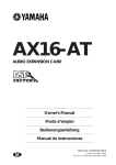
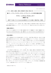
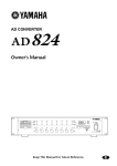
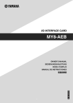
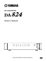
DA CONVERTER
Owner’s Manual
PEAK
PEAK
NOMINAL
NOMINAL
SIGNAL
LOCK
POWER
ON
OFF
SIGNAL
1
2
3
4
5
6
7
8
DA CONVERTER
Keep This Manual For Future Reference.
E
FCC INFORMATION (U.S.A.)
1. IMPORTANT NOTICE: DO NOT MODIFY THIS UNIT! This product, when installed as indicated in the instructions contained in this manual, meets FCC
requirements. Modifications not expressly approved by Yamaha may void your authority, granted by the FCC, to use the product.
2. IMPORTANT: When connecting this product to accessories and/or another product use only high quality shielded cables. Cable/s supplied with this product MUST
be used. Follow all installation instructions. Failure to follow instructions could void your FCC authorization to use this product in the USA.
3. NOTE: This product has been tested and found to comply with the requirements listed in FCC Regulations, Part 15 for Class “B” digital devices. Compliance with
these requirements provides a reasonable level of assurance that your use of this product in a residential environment will not result in harmful interference with
other electronic devices. This equipment generates/uses radio frequencies and, if not installed and used according to the instructions found in the users manual, may
cause interference harmful to the operation of other electronic devices. Compliance with FCC regulations does not guarantee that interference will not occur in all
installations. If this product is found to be the source of interference, which can be determined by turning the unit “OFF” and “ON”, please try to eliminate the
problem by using one of the following measures: Relocate either this product or the device that is being affected by the interference. Utilize power outlets that are on
different branch (circuit breaker or fuse) circuits or install AC line filter/s. In the case of radio or TV interference, relocate/reorient the antenna. If the antenna lead-in
is 300 ohm ribbon lead, change the lead-in to coaxial type cable. If these corrective measures do not produce satisfactory results, please contact the local retailer
authorized to distribute this type of product. If you can not locate the appropriate retailer, please contact Yamaha Corporation of America, Electronic Service
Division, 6600 Orangethorpe Ave, Buena Park, CA 90620
The above statements apply ONLY to those products distributed by Yamaha Corporation of America or its subsidiaries.
WARNING: THIS APPARATUS MUST BE EARTHED
IMPORTANT
THE WIRES IN THIS MAINS LEAD ARE COLOURED IN
ACCORDANCE WITH THE FOLLOWING CODE:
GREEN-AND-YELLOW :
EARTH
BLUE :
NEUTRAL
BROWN :
LIVE
As the colours of the wires in the mains lead of this apparatus may
not correspond with the coloured markings identifying the terminals in
your plug, proceed as follows:
The wire which is coloured GREEN and YELLOW must be
connected to the terminal in the plug which is marked by the letter E
or by the safety earth symbol
or coloured GREEN and YELLOW.
The wire which is coloured BLUE must be connected to the terminal
which is marked with the letter N or coloured BLACK.
The wire which is coloured BROWN must be connected to the
terminal which is marked with the letter L or coloured RED.
* This applies only to products distributed by YAMAHA KEMBLE
MUSIC (U.K.) LTD.
i
Important Information
Please read before operating the DA824
Warnings
• Do not subject the DA824 to extreme temperatures, humidity, direct sunlight, or dust,
which could be a potential fire or electrical shock hazard.
• Do not allow water to enter the DA824 or allow it to become wet. Fire or electrical shock
may result.
• Connect the power cord only to an AC outlet of the type stated in this Owner’s Manual
or as marked on the DA824. Failure to do so is a fire and electrical shock hazard.
• Hold the power-cord plug when disconnecting from an AC outlet. Never pull the cord.
A power cord damaged through pulling is a potential fire and electrical shock hazard.
• Do not touch the power plug with wet hands. Doing so is a potential electrical shock
hazard.
• Do not place heavy objects, including the DA824, on top of the power cord. A damaged
power cord is a fire and electrical shock hazard. In particular, be careful not to place
heavy objects on a power cord covered by a carpet.
• Do not scratch, bend, twist, pull, or heat the power cord. A damaged power cord is a
fire and electrical shock hazard.
• If the power cord is damaged (e.g., cut or a bare wire is exposed), ask your dealer for a
replacement. Using the DA824 with a damaged power cord is a fire and electrical shock
hazard.
• Do not plug several devices into the same AC outlet. This may overload the AC outlet,
and could be a fire or electrical shock hazard. It may also affect the performance of some
equipment.
• If you notice any abnormality, such as smoke, odor, or noise, or if a foreign object or
liquid gets inside the DA824, turn it off immediately. Remove the power cord from the
AC outlet and consult your dealer for repair. Using the DA824 in this condition is a fire
and electrical shock hazard.
• Do not place small objects on top of the DA824. Metal objects falling inside the DA824
is a fire and electrical shock hazard.
• If a foreign object or water gets inside the DA824, turn it off immediately. Remove the
power cord from the AC outlet and consult your dealer for repair. Using the DA824 in
this condition is a potential fire and electrical shock hazard.
• Should the DA824 be dropped or the cabinet be damaged, turn off the power, remove
the power plug from the AC outlet, and contact your dealer. If you continue using the
unit without heeding this instruction, fire or electrical shock may result.
• Do not remove the DA824’s cover. You could receive an electrical shock. If you think
internal inspection, maintenance, or repair is necessary, contact your dealer.
• Do not attempt to modify the DA824. This is a potential fire and electrical shock hazard.
• Do not block the DA824 ventilation slots. Blocking the ventilation slots is a potential
fire hazard.
• Do not place a container with liquid or small metal objects on top of this unit. Liquid
or metal objects inside this unit are a fire and electrical shock hazard.
DA824—Owner’s Manual
ii
• Be sure to connect to an appropriate outlet with a protective grounding connection.
Improper grounding can result in electrical shock.
Cautions
• If this device is to be mounted in an EIA-standard rack, leave the back of the rack open
and make sure that it is at least 10 cm away from walls or surfaces. Also, if this device is
to be mounted with devices that tend to generate heat, such as power amplifiers, be sure
to keep an adequate gap between this device and the heat-generating devices or install
ventilation panels to prevent high temperatures from developing inside this device.
Under these conditions these devices can be rackmounted. Inadequate ventilation can
result in overheating, possibly causing damage to the device(s), or even fire.
• Use the DA824 in an environment where the temperature is between 10˚C and 35˚C
(50˚F and 95˚F).
• Turn off audio devices when connecting them to the DA824, and use only the cables
specified in the relevant owner’s manuals.
• If you plan not to use the DA824 for a long period of time, remove the power cord from
the AC outlet. Leaving the DA824 connected is a potential fire hazard.
• Do not use benzene, thinner, cleaning detergent, or a chemical cloth to clean the
DA824. Use only a soft, dry cloth.
• If the DA824 is stored in a cold place (e.g., overnight in a car), and then moved to a
warmer environment, or the temperature rises sharply, condensation may form inside
the DA824, which may affect performance. In such cases, the DA824 should be allowed
to acclimatize for about one hour before use.
• When the wordclock source is changed, the DA824’s analog outputs may produce
noise, especially if an MY8-AT I/O card is installed, so turn down your power amps
beforehand. Likewise, when changing the wordclock source on the wordclock master
device (e.g., AD824 or DME32), turn down your power amps beforehand, or turn off
the DA824.
• When setting up the product, make sure that the AC outlet you are using is easily accessible. If some trouble or malfunction occurs, immediately turn off the power switch and
disconnect the plug from the outlet. Even when the power switch is turned off, electricity is still flowing to the product at the minimum level. When you are not using the
product for a long time, make sure to unplug the power cord from the wall AC outlet.
Interference
The DA824 uses high-frequency digital circuits that may cause interference on radio
and television equipment located nearby. If interference is a problem, relocate the
affected equipment.
DA824 Exclusion of Certain Responsibility
Manufacturer, importer, or dealer shall not be liable for any incidental damages including personal injury or any other damage caused by improper use or operation of the
DA824.
Yamaha cannot be held responsible for any loss of data or data damage due to improper
use or operation of the DA824.
DA824—Owner’s Manual
iii
Package Contents
The DA824 package should contain the following items. Contact your Yamaha dealer if
anything is missing.
• DA824 DA Converter
• Power cord
• This manual
Trademarks
ADAT MultiChannel Optical Digital Interface is a trademark of Alesis Corporation.
Tascam Digital Interface is a trademark and Tascam and Teac are registered trademarks
of Teac Corporation. Yamaha is a trademark of Yamaha Corporation. All other trademarks are the property of their respective holders and are hereby acknowledged.
Copyright
No part of the DA824 software or this Owner’s Manual may be reproduced or distributed in any form or by any means without the prior written authorization of Yamaha
Corporation.
© 2000 Yamaha Corporation. All rights reserved.
DA824—Owner’s Manual
iv
Contents
Contents
1
Introduction . . . . . . . . . . . . . . . . . . . . . . . . . . . . . . . . 1
Welcome . . . . . . . . . . . . . . . . . . . . . . . . . . . . . . . . . . . . . . . . . . . . . . . . . . . . . . . . . . .
Installation . . . . . . . . . . . . . . . . . . . . . . . . . . . . . . . . . . . . . . . . . . . . . . . . . . . . . . . . .
Setting the Maximum Output Level . . . . . . . . . . . . . . . . . . . . . . . . . . . . . . . . . . . .
Connecting the Power Cord . . . . . . . . . . . . . . . . . . . . . . . . . . . . . . . . . . . . . . . . . . .
Turning On the Power . . . . . . . . . . . . . . . . . . . . . . . . . . . . . . . . . . . . . . . . . . . . . . .
2
1
1
1
1
1
Touring the DA824 . . . . . . . . . . . . . . . . . . . . . . . . . . . 2
Front Panel . . . . . . . . . . . . . . . . . . . . . . . . . . . . . . . . . . . . . . . . . . . . . . . . . . . . . . . . . 2
Rear Panel . . . . . . . . . . . . . . . . . . . . . . . . . . . . . . . . . . . . . . . . . . . . . . . . . . . . . . . . . . 3
3
Digital I/O Cards . . . . . . . . . . . . . . . . . . . . . . . . . . . . . 4
About Digital I/O Cards . . . . . . . . . . . . . . . . . . . . . . . . . . . . . . . . . . . . . . . . . . . . . . 4
Card Specifications . . . . . . . . . . . . . . . . . . . . . . . . . . . . . . . . . . . . . . . . . . . . . . . . . . 4
Installing I/O Cards . . . . . . . . . . . . . . . . . . . . . . . . . . . . . . . . . . . . . . . . . . . . . . . . . . 5
4
Hookup Examples . . . . . . . . . . . . . . . . . . . . . . . . . . . . 6
Basic AES/EBU Connection . . . . . . . . . . . . . . . . . . . . . . . . . . . . . . . . . . . . . . . . . . .
Basic ADAT Connection . . . . . . . . . . . . . . . . . . . . . . . . . . . . . . . . . . . . . . . . . . . . . .
AES/EBU Connection with Splitter Cable . . . . . . . . . . . . . . . . . . . . . . . . . . . . . . .
Dual ADAT Connection . . . . . . . . . . . . . . . . . . . . . . . . . . . . . . . . . . . . . . . . . . . . . .
5
6
6
7
7
Wordclocks . . . . . . . . . . . . . . . . . . . . . . . . . . . . . . . . . 8
About Wordclocks . . . . . . . . . . . . . . . . . . . . . . . . . . . . . . . . . . . . . . . . . . . . . . . . . . . 8
Wordclock Hookup Examples . . . . . . . . . . . . . . . . . . . . . . . . . . . . . . . . . . . . . . . . . 8
Wordclock Termination . . . . . . . . . . . . . . . . . . . . . . . . . . . . . . . . . . . . . . . . . . . . . . 9
Appendix . . . . . . . . . . . . . . . . . . . . . . . . . . . . . . . . . . . 10
Specifications . . . . . . . . . . . . . . . . . . . . . . . . . . . . . . . . . . . . . . . . . . . . . . . . . . . . . . . 10
Dimensions . . . . . . . . . . . . . . . . . . . . . . . . . . . . . . . . . . . . . . . . . . . . . . . . . . . . . . . . 12
DA824—Owner’s Manual
Introduction
1
1 Introduction
Welcome
Thank you for choosing the Yamaha DA824 DA Converter.
The DA824 is a high-performance 8-channel digital-to-analog converter, with 24-bit
linear digital-to-analog converters and 128-times oversampling providing a typical
dynamic range of 110 dB. Optional mini YGDAI (Yamaha General Digital Audio Interface) cards offer a variety of digital input interfaces, with support for all the popular digital audio interconnect formats, including AES/EBU, ADAT, and Tascam TDIF-1.
Installation
The DA824 can be used freestanding on a stable surface, somewhere that complies with
the important information at the beginning of this manual, or mounted in a rack.
When mounting the DA824 in a rack, leave adequate ventilation space around the
DA824 (at least 10 cm of free space behind). If the DA824 is mounted in a portable rack
case, keep the rear of the case open when using the DA824, so as not to obstruct the flow
of air from the air vents. Do not mount the DA824 next to equipment that produces a
lot of heat, such as a power amplifier.
Setting the Maximum Output Level
Inside the DA824 are eight output-level switches for presetting the maximum output
level of each analog output. Maximum output levels settings are: +24 dB, +18 dB,
+15 dB, and +4 dBV. See you Yamaha dealer for more information.
Connecting the Power Cord
Warning: Turn off all equipment before making any connections.
Connect the power-cord plug to a suitable AC wall outlet, one that conforms to the
power supply requirements stated on the DA824 rear panel.
Turning On the Power
To prevent audible thumps and clicks, turn on your audio equipment in
the following order (reverse this order when turning off your equipment)—sound sources, mixer or recorder (e.g., 02R, DME32, D24, etc.),
DA824, power amplifiers.
1
POWER
ON
OFF
Press the [POWER] switch to turn on the DA824.
The DA824 starts up and the POWER indicator lights up.
2
Press the [POWER] switch again to turn off the DA824.
The POWER indicator goes out.
DA824—Owner’s Manual
2
Chapter 2—Touring the DA824
2 Touring the DA824
Front Panel
1
2 34
PEAK
PEAK
NOMINAL
NOMINAL
SIGNAL
LOCK
POWER
ON OFF
SIGNAL
1
2
3
4
5
6
7
8
DA CONVERTER
A PEAK, NOMINAL & SIGNAL indicators
These indicators show the signal level of each channel.
PEAK—This indicator lights up when the signal level is 3 dB below full-scale output.
NOMINAL—This indicator lights up when the signal level is 14 dB below full-scale
output.
SIGNAL—This indicator lights up when the signal level is 34 dB below full-scale output.
B LOCK indicator
This indicator shows whether or not the DA824 is locked to the wordclock source. See
“Wordclocks” on page 8 for more information.
C POWER indicator
This indicator lights up when the DA824 is powered up.
D POWER switch
This switch is used to turn on the power to the DA824. It’s recessed to prevent accidental
operation. See “Turning On the Power” on page 1 for more information.
DA824—Owner’s Manual
3
Rear Panel
Rear Panel
1
DA CONVERTER
MODEL DA824
2
COM
3 4
5
WORD CLOCK
OUTPUT
(BAL)
THRU
75Ω
OFF ON
IN
8
7
6
5
4
3
2
1
8
7
6
5
4
3
2
1
SLOT
6
7
A COM port
This port is for updating the DA824’s internal firmware and is not used in normal operation.
B WORD CLOCK THRU connector
This BNC connector transmits the wordclock signal received at the WORD CLOCK IN.
C WORD CLOCK 75Ω ON/OFF switch
This switch is used to terminate the wordclock signal received at the WORD CLOCK
IN. See “Wordclocks” on page 8 for more information.
D WORD CLOCK IN connector
This BNC connector is used to connect an external wordclock source. Normally, the
DA824 locks to a wordclock signal derived from the SLOT digital audio inputs, but
when a usable wordclock signal is present at the WORD CLOCK IN connector, this is
used instead. See “Wordclocks” on page 8 for more information.
E OUTPUT (BAL) connectors
These male XLR-3-32 type connectors and 1/4" phone jack (TRS) connectors are the
analog outputs for each channel. Both types of connector are electronically balanced.
XLR connectors are wired as follows: pin-1 ground, pin-2 hot (+), and pin-3 cold (–).
When using both the XLR and phone jack output of a channel at the same time, ensure
that the total load is greater than 600Ω.
F Power cable
This power cable is used to connect the DA824 to an AC outlet. See “Connecting the
Power Cord” on page 1 for more information.
G SLOT
This slot is for use with optional mini YGDAI cards, which offer various digital input
options. See “Digital I/O Cards” on page 4 for more information.
DA824—Owner’s Manual
4
Chapter 3—Digital I/O Cards
3 Digital I/O Cards
About Digital I/O Cards
For digital input, the DA824 uses optional mini YGDAI (Yamaha General Digital Audio
Interface) cards, which are available in all the popular digital audio interconnect formats, including AES/EBU, ADAT, and Tascam TDIF-1.
The following digital I/O cards are currently available. See the Yamaha Professional
Audio Web site at the following address for up-to-date news on mini YGDAI cards:
<http://www.yamaha.co.jp/product/proaudio/homeenglish/>.
MY8-AT—ADAT
The MY8-AT card provides ADAT format digital I/O via two MultiChannel Optical
Digital Interface connectors, and supports 16-, 20-, and 24-bit wordlengths.
MY8-AE—AES/EBU
The MY8-AE card provides AES/EBU format digital I/O via a 25-pin D-sub connector,
and supports 16-, 20-, and 24-bit wordlengths.
MY8-TD—Tascam TDIF-1
The MY8-TD card provides Tascam TDIF-1 format digital I/O via a 25-pin D-sub connector, and supports 16-, 20-, and 24-bit wordlengths. A BNC connector is provided
for wordclock output.
MY8-TD cards feature a device selector switch (EXT: 88/INT: 38) that should be set to
match the device being connected. This should be set to “EXT: 88” when connecting a
Tascam DA-88, or “INT: 38” when connecting a Tascam DA-38, DME32, or other
device.
Card Specifications
The following table provides specifications for the DA824-compatible I/O cards.
Card
Format
In
Out
Wordlength
Connectors
MY8-AT
ADAT I/O
8
8
16, 20, 24
Optical x2
MY8-AE
AES/EBU I/O
8
8
16, 20, 24
25-pin D-sub
(cable not included)
MY8-TD
Tascam TDIF-1 I/O
8
8
16, 20, 24
25-pin D-sub,
BNC wordclock out
DA824—Owner’s Manual
Installing I/O Cards
5
Installing I/O Cards
This section explains how to install mini YGDAI cards in the DA824.
1
Turn off the DA824.
2
Undo the two fixing screws and remove the slot cover, as shown below.
CO
M
TH
RU
SL
OT
W
OR
D
CL
O
CK
7
ON 5Ω
OF
F IN
8
8
Keep the cover and fixing screws in a safe place for future use.
3
Insert the card between the guide rails and slide it all the way into the slot,
as shown below. You may have to push firmly to plug the card into the DA824
connector.
CO
M
TH
RU
SL
OT
W
OR
D
CL
O
CK
7
ON 5Ω
OF
F IN
8
8
4
Secure the card using the attached thumbscrews. Do not leave the thumbscrews loose, as the card will not be grounded correctly.
DA824—Owner’s Manual
6
Chapter 4—Hookup Examples
4 Hookup Examples
In the following hookup examples, the “Digital Audio Device” could be any device with
a compatible AES/EBU or ADAT interface, including the following Yamaha products
with the necessary I/O cards installed: DME32 Digital Mixing Engine, 02R Digital
Recording Console, 03D Digital Mixing Console, 01V Digital Mixing Console, or D24
Digital Multitrack Recorder.
Basic AES/EBU Connection
This example shows how the
DA824 can be connected to a
digital audio device with an
AES/EBU interface by using
an MY8-AE I/O card and a
25-pin D-sub AES/EBU connecting cable.
Digital Audio Device
(DME32, 02R, D24, etc.)
AES/EBU I/O
AES/EBU cable
SLOT: MY8-AE
DA824
PEAK
PEAK
NOMINAL
LOCK
POWER
ON
OFF
NOMINAL
SIGNAL
SIGNAL
1
2
3
4
5
6
7
8
DA CONVERTER
Analog output x8
Basic ADAT Connection
This example shows how the
DA824 can be connected to a
digital audio device with an
ADAT interface by using a
MY8-AT I/O card and standard ADAT connecting cable.
Digital Audio Device
(DME32, 02R, D24, etc.)
OUT ADAT I/O
ADAT cable
DA824
IN
SLOT: MY8-AT
PEAK
PEAK
NOMINAL
NOMINAL
SIGNAL
LOCK
POWER
ON
OFF
SIGNAL
1
2
3
4
5
6
7
8
DA CONVERTER
Analog output x8
DA824—Owner’s Manual
7
AES/EBU Connection with Splitter Cable
AES/EBU Connection with Splitter Cable
This example shows how both an AD824 and DA824 can be connected to a digital
audio device with a single AES/EBU interface by using MY8-AE I/O cards and a custom
AES/EBU splitter cable. Pin wiring details for the AES/EBU interface are supplied with
each MY8-AE I/O card. The digital audio device is the wordclock master, with the
AD824 receiving its wordclock via a BNC connection, the DA824, via its slot input.
Digital Audio Device
(DME32, 02R, D24, etc.)
WC OUT
AES/EBU I/O
BNC cable
Custom AES/EBU splitter cable
AD824
WORD CLOCK
INTERNAL
44.1kHz 48kHz
SLOT: MY8-AE
WC IN
BNC
PEAK
SLOT
PEAK
NOMINAL
NOMINAL
SIGNAL
GAIN
PEAK
POWER
ON
OFF
dB
SLOT: MY8-AE
DA824
PEAK
NOMINAL
SIGNAL
1
2
3
4
5
6
7
LOCK
POWER
ON
OFF
NOMINAL
SIGNAL
SIGNAL
1
+48V
+48V
2
3
4
5
6
7
8
+48V MASTER
OFF ON
8
SEL
SEL
AD CONVERTER
DA CONVERTER
Analog output x8
Analog input x8
Dual ADAT Connection
This example shows how both an AD824 and DA824 can be connected to a digital
audio device with standard ADAT I/O by using MY8-AT I/O cards and standard ADAT
connecting cables. The digital audio device is the wordclock master, with the AD824
receiving its wordclock via a BNC connection, the DA824, via its slot input.
Digital Audio Device
(DME32, 02R, D24, etc.)
IN
WC OUT
BNC cable
OUT
ADAT I/O
ADAT cables
AD824
WORD CLOCK
INTERNAL
44.1kHz 48kHz
OUT
SLOT: MY8-AT
WC IN
BNC
PEAK
SLOT
PEAK
NOMINAL
NOMINAL
SIGNAL
GAIN
PEAK
POWER
ON
OFF
dB
IN
SLOT: MY8-AT
DA824
SIGNAL
PEAK
NOMINAL
NOMINAL
SIGNAL
1
SEL
2
3
4
5
6
7
LOCK
POWER
ON
OFF
SIGNAL
1
+48V
+48V
2
3
4
5
6
7
8
+48V MASTER
OFF ON
8
SEL
AD CONVERTER
Analog input x8
DA CONVERTER
Analog output x8
DA824—Owner’s Manual
8
Chapter 5—Wordclocks
5 Wordclocks
About Wordclocks
For correct operation and digital-to-analog processing, it is essential that the DA824 is
wordclock locked to the digital audio device transmitting the digital audio signals. Normally, the DA824 locks to a wordclock signal derived from the SLOT digital audio
inputs, but when a usable wordclock signal is present at the WORD CLOCK IN connector, this is used instead.
The LOCK indicator lights up when the DA824 is locked to the wordclock source and
synchronized to the digital audio signal. It flashes if the DA824 is not synchronized to
the digital audio signal.
Note: When the wordclock source is changed, the DA824’s analog outputs may produce
noise, especially if an MY8-AT I/O card is installed, so turn down your power amps beforehand. Likewise, when changing the wordclock source on the wordclock master device (e.g.,
AD824 or DME32), turn down your power amps beforehand, or turn off the DA824.
Wordclock Hookup Examples
In this example, the DA824
sources the wordclock signal
from the SLOT digital audio
inputs.
Digital Audio Device
(DME32, 02R, D24, etc.)
Digital I/O
MY8-xx
DA824
PEAK
PEAK
NOMINAL
LOCK
POWER
ON
OFF
NOMINAL
SIGNAL
SIGNAL
1
2
3
4
5
6
7
8
DA CONVERTER
In this example, the DA824
sources the wordclock signal
automatically from the WORD
CLOCK IN connector.
Digital Audio Device
(DME32, 02R, D24, etc.)
Digital I/O
Wordclock out
(BNC)
MY8-xx
DA824
WORD CLOCK IN
PEAK
PEAK
NOMINAL
NOMINAL
SIGNAL
LOCK
POWER
ON
OFF
SIGNAL
1
2
3
4
5
6
7
8
DA CONVERTER
DA824—Owner’s Manual
Wordclock Termination
9
Wordclock Termination
For correct and reliable operation, wordclock signals distributed via BNC cables must
be terminated correctly. Termination is typically applied at the last device, although it
depends on the distribution method being used. The DA824’s WORD CLOCK 75Ω
ON/OFF switch allows the DA824 to be connected in a variety of ways. The following
examples show three ways in which wordclock signals can be distributed and how termination should be applied in each case.
Wordclock Distribution Box
In this example, a dedicated wordclock distribution box is used to supply a wordclock
signal to each device individually. Termination is applied at each device.
WC OUT
(BNC)
Wordclock
master
WC IN (BNC)
Wordclock
distribution box
WC IN (BNC)
WC IN (BNC)
WC IN (BNC)
Device-A
Device-B
Device-C
Device-D
Termination = ON
Termination = ON
Termination = ON
Termination = ON
Wordclock slave
Wordclock slave
Wordclock slave
Wordclock slave
Bus Distribution
In this example, the wordclock signal is distributed via a common line. Termination is
applied at the last device only.
Wordclock
master
WC OUT (BNC)
WC IN (BNC)
WC IN (BNC)
WC IN (BNC)
WC IN (BNC)
Device-A
Device-B
Device-C
Device-D
Termination = OFF
Termination = OFF
Termination = OFF
Termination = ON
Wordclock slave
Wordclock slave
Wordclock slave
Wordclock slave
Daisy Chain Distribution
In this example, the wordclock signal is distributed in a “daisy-chain” fashion, with each
device feeding the wordclock signal on to the next. Termination is applied at the last
device only. This method of distribution is not recommended for larger systems.
Wordclock
master
WC OUT (BNC)
WC IN
(BNC)
WC OUT
(BNC)
WC IN
(BNC)
WC OUT
(BNC)
WC IN
(BNC)
Device-A
Device-B
Device-C
Termination = OFF
Termination = OFF
Termination = ON
Wordclock slave
Wordclock slave
Wordclock slave
DA824—Owner’s Manual
10
Appendix
Appendix
Specifications
MY8-AE, MY8-TD
39.69–50.88 kHz
MY8-AT
41.013–50.88 kHz
Sampling rate
DA conversion resolution
24-bit linear, 128-times oversampling
Frequency response
–3, +1 dB, 20 Hz–20 kHz
Dynamic
Range1
110 dB (typical)
Gain Error
±1 dB @ 1 kHz
0.05%, 20 Hz–20 kHz
THD2
0.01% full scale output @ 1 kHz
Hum & Noise
Level1
–92 dBu (typical)
Crosstalk
–70 dB between adjacent channels @ 1 kHz
Signal Delay
0.57 ms (digital input to analog output, fs = 48 kHz)
Indicators
PEAK
3 dB below full scale
NOMINAL
14 dB below full scale
SIGNAL
34 dB below full scale
LOCK
Wordclock lock
POWER
Power on/off
Power requirements
U.S.A. & Canada 120 V AC, 60 Hz
Europe 230 V AC, 50 Hz
Power consumption
40 W
Dimensions (W × H × D)
480 × 97.5 × 366.8 mm (18.9 x 3.84 x 14.44 inches)
Weight
7.5 kg (16.53 lbs)
Free-air operating temperature
10˚ C to 35˚ C (50˚ F to 95˚ F)
Storage temperature
–20˚ C to 60˚ C (–4˚ F to 140˚ F)
Power cord length
1.9 m
Supplied Accessories
Owner’s Manual
1. Measured with a 6 dB/octave filter at 12.7 kHz; equivalent to a 20 kHz filter with infinite
dB/octave attenuation.
2. 6 dB/octave filter @ 80 kHz.
* Where dB represents a specific voltage, 0 dB is referenced to 0.775 V rms, 0 dBV is referenced to 1.00 V rms.
DA824—Owner’s Manual
Specifications
11
Analog Output
Connection
GAIN SW
For Use
with
Nominal
Output Level
Nominal
Max.
before clip
+24 dB
+10 dB
(2.45 V)
+24 dB
(12.28 V)
+18 dB
+4 dB
(1.23 V)
+18 dB
(6.16 V)
+15 dB
+1 dB
(0.87 V)
+15 dB
(4.36 V)
+4 dBV
–10 dBV
(0.316 V)
+4 dBV
(1.58 V)
150 Ω lines
OUTPUT 1–81
1.
2.
3.
*
Actual
Source
Impedance
600 Ω lines
Connector
XLR-3-32
type
(balanced)2
&
TRS phone
jack
(balanced)3
24-bit 128-times oversampling D/A converters.
XLR-type connectors are electronically balanced (pin 1 = ground, pin 2 = hot, pin 3 = cold).
TRS phone jacks are electronically balanced (tip = hot, ring = cold, sleeve = ground).
Where dB represents a specific voltage, 0 dB is referenced to 0.775 V rms, 0 dBV is referenced to 1.00 V rms.
Digital I/O
Connection
Format
Level/Impedance
Connector
COM
—
RS232C
9-pin D-sub (male)
WORD CLOCK IN
—
TTL, 75Ω (ON/OFF)
BNC
WORD CLOCK THRU
—
TTL, 75Ω
BNC
mini YGDAI
—
—
SLOT
DA824—Owner’s Manual
12
Appendix
Dimensions
30
48
30
274
D: 366.8
355
(33)
13
430
W: 480
88
H: 97.5
67.5
345
67.5
Specifications and external appearance subject to change without notice.
For European Model
Purchaser/User Information specified in EN55103-1 and EN55103-2.
Inrush Current: 10A
Conformed Environment: E1, E2, E3 and E4
DA824—Owner’s Manual
Unit: mm
YAMAHA CORPORATION
V554060 R3 1 IP 20
07 08 400 AP Printed in Japan
Pro Audio & Digital Musical Instrument Division
P.O. Box 3, Hamamatsu, 430-8651, Japan