1
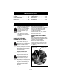
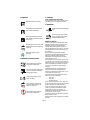
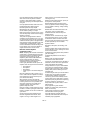
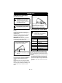
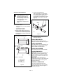
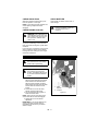
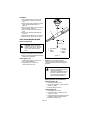
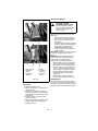
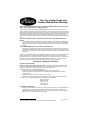
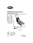
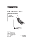
Wide Area Walk Mower
Owner/Operator Manual
Models
911403 – WAW 1034
911407 – WAW 1034 CARB
ENGLISH
01254000B 4/08
Printed in USA
TABLE OF CONTENTS
Safety . . . . . . . . . . . . . . . . . . . . . . . . . . . 4
Storage . . . . . . . . . . . . . . . . . . . . . . . . . 22
Assembly . . . . . . . . . . . . . . . . . . . . . . . . 9
Troubleshooting . . . . . . . . . . . . . . . . . 22
Controls and Features . . . . . . . . . . . . 11
Service Parts . . . . . . . . . . . . . . . . . . . . 23
Operation . . . . . . . . . . . . . . . . . . . . . . . 12
Accessories . . . . . . . . . . . . . . . . . . . . . 23
Maintenance. . . . . . . . . . . . . . . . . . . . . 15
Specifications . . . . . . . . . . . . . . . . . . . 24
Service and Adjustments . . . . . . . . . . 17
Warranty. . . . . . . . . . . . . . . . . . . . . . . . 25
INTRODUCTION
NON-ENGLISH MANUALS
THE MANUAL
Manuals in languages other than
English may be obtained from
your Dealer. Visit your dealer or
www.ariens.com for a list of
languages available for your
equipment.
Manuals printed in languages
other than English are also
available as a free download on
our website:
http://www.ariens.com
MANUALES EN IDIOMAS
DIFERENTES DEL INGLES
Puede obtener manuales en
idiomas diferentes del inglés en su
distribuidor. Visite a su distribuidor
o vaya a www.ariens.com para
obtener una lista de idiomas
disponibles para su equipo.
También puede imprimir manuales
en idiomas diferentes del inglés
descargándolos gratuitamente de
nuestra página Web:
Before using the unit, carefully and
completely read your manuals. The contents
will give you an understanding of safety
instructions and controls during normal
operation and maintenance.
All reference to left, right, front, or rear are
given from the operator’s position, facing the
direction of forward travel.
SERVICE AND REPLACEMENT
PARTS
When ordering replacement parts or making
service inquiries, know the Model and Serial
numbers of your unit and engine.
Numbers are located on the product
registration form in the unit literature
package. They are also printed on a serial
number label, located on the frame of your
unit (Figure 1).
Unit Serial
Number Label
Engine Serial
Number Label
http://www.ariens.com
MANUELS NON ANGLAIS
Des manuels dans différentes
langues sont disponibles chez
votre revendeur. Rendez-vous
chez votre revendeur ou allez sur
le site www.ariens.com pour
consulter la liste des langues
disponibles pour votre équipement.
Les manuels imprimés dans des
langues différentes de l’anglais
sont également disponibles en
téléchargement gratuit sur notre
site Web :
http://www.ariens.com
GB - 2
OM1600
Figure 1
DEALER DELIVERY
• Record Unit Model and Serial numbers
here:
• Record Engine Model & Serial numbers
here:
PRODUCT REGISTRATION
The Ariens dealer must register the product
at the time of purchase. Registering the
product will help the company process
warranty claims or contact you with the latest
service information. All claims meeting
requirements during the limited warranty
period will be honored, whether or not the
product registration card is returned. Keep a
proof of purchase if you do not register your
unit.
Customer Note: If the Dealer does not
register your product, please fill out, sign and
return the product registration card to Ariens
or go to www.ariens.com on the internet.
UNAUTHORIZED REPLACEMENT
PARTS
Dealer should:
1. Check that all assembly and
adjustments have been properly
completed.
2. Fill out Original Purchaser Registration
Card and return the card to Ariens.
3. Explain Ariens Limited Warranty Policy.
4. Explain recommended lubrication and
maintenance. Advise customer on
adjustments. Remind customer to
change oil in 4 cycle engine crankcase
after first five (5) hours of operation.
5. Instruct customer on controls and
operation of unit. Discuss and
emphasize the Safety Rules. Give
customer Owner/Operator, Parts, and
Engine manuals. Advise customer to
thoroughly read and understand them.
DISCLAIMER
Ariens reserves the right to discontinue,
make changes to, and add improvements
upon its products at any time without public
notice or obligation.The descriptions and
specifications contained in this manual were
in effect at printing. Equipment described
within this manual may be optional. Some
illustrations may not apply to your unit.
Use only Ariens replacement parts.
Replacing any part on this vehicle with
anything other than an Ariens authorized
replacement part may adversely affect the
performance, durability, or safety of this unit
and may void the warranty. Ariens disclaims
liability for any claims or damages, whether
warranty, property damage, personal injury or
death arising out of the use of unauthorized
replacement parts. To locate your nearest
Ariens Dealer, go to www.ariens.com on the
internet.
GB - 3
SAFETY
CAUTION: POTENTIALLY
HAZARDOUS SITUATION! If not
avoided, MAY RESULT in minor or
moderate injury. It may also be
used to alert against unsafe
practices.
WARNING: This cutting machine
is capable of amputating hands
and feet and throwing objects.
Failure to observe the safety
instructions in the manuals and
on decals could result in serious
injury or death.
Slopes are a major factor related
to slip and fall accidents.
Operation on all slopes requires
extra caution.
Tragic accidents can occur if the
operator is not alert to the
presence of children. Never
assume that children will remain
where you last saw them.
Gasoline is extremely flammable
and the vapors are explosive,
handle with care.
Stop unit and engine, remove key
(if equipped) and allow moving
parts to stop before leaving
operator’s position.
NOTATIONS
NOTE: General reference information for
proper operation and maintenance practices.
IMPORTANT: Specific procedures or
information required to prevent damage to
unit or attachment.
PRACTICES AND LAWS
Practice usual and customary safe working
precautions, for the benefit of yourself and
others. Understand and follow all safety
messages. Be alert to unsafe conditions and
the possibility of minor, moderate, or serious
injury or death. Learn applicable rules and
laws in your area.
REQUIRED OPERATOR
TRAINING
SAFETY ALERTS
Look for these symbols to point
out important safety precautions.
They mean:
Attention!
Original purchaser of this unit was instructed
by the seller on safe and proper operation. If
anyone other than the original purchaser will
use the unit, ALWAYS provide this manual
and any needed safety training before
operation.
Personal Safety Is Involved!
Become Alert!
Obey The Message!
The safety alert symbols above and signal
words below are used on decals and in this
manual.
Read and understand all safety messages.
DANGER: IMMINENTLY
HAZARDOUS SITUATION! If not
avoided, WILL RESULT in death or
serious injury.
WARNING: POTENTIALLY
HAZARDOUS SITUATION! If not
avoided, COULD RESULT in
death or serious injury.
GB - 4
SAFETY DECALS AND
LOCATIONS
ALWAYS replace missing or damaged safety
decals. Refer to Figure 2 for safety decal
locations.
+
2
1
05365400A
3
1
5
4
Figure 2
1. DANGER!
Do not operate mower unless
guards are in operating position
or entire bagger is attached.
TO AVOID SERIOUS INJURY OR DEATH
Read the operator’s manual.
OL1812
Keep safety devices (guards,
shields, switches, etc.) in place
and working.
OL1801
Keep children and others away
from unit while operating.
•
Go across slopes, not up and down.
•
Look down and behind before and
while moving backward.
•
Do not park on a slope unless
chocked or blocked.
•
Do not allow operation of machine by
untrained personnel.
OL4370
Never direct discharge toward
other people. Thrown objects can
cause injury.
OL0910
GB - 5
2. WARNING!
4. DANGER!
KEEP HANDS AND FEET AWAY
Do not operate mower unless guards are in
operating position or bagger is attached.
Read the operator’s manual.
5. WARNING!
OL1801
Always stand clear of discharge
area.
Keep children and others away
from unit while operating.
OL1814
OL4370
Do not operate mower unless
bagger is attached or guards
are in operating position.
Never direct discharge toward
other people. Thrown objects can
cause injury.
SAFETY RULES
OL0910
Shut off engine, remove key, and
read manual before you adjust or
repair unit.
OL1812
Wear appropriate hearing
protection.
3. DANGER! ROTATING PARTS
Always keep feet and hands
away from rotating parts.
OL1809
Always stand clear of discharge
area. Do not direct discharge
toward other people.
OL1810
Keep people away from unit
while operating.
OL18111
Shut off engine, remove key,
and read manual before you
adjust or repair unit.
OL1812
NO STEP! Always keep feet
away from rotating parts.
OL1813
OL1815
If unit is to be used by someone other than
original purchaser; loaned, rented or sold,
ALWAYS provide this manual and any
needed safety training before operation.
Learn applicable rules and laws in your area,
including those that may restrict the age of
the operator.
Read, understand and follow all safety
practices in Owner/Operator Manual before
beginning assembly. Failure to follow
instructions could result in personal injury
and/or damage to unit.
If the operator or the mechanic cannot read
the manual, it is the owner’s responsibility to
explain it to them. Only the user can prevent
and is responsible for accidents or injuries
occurring to themselves, other people or
property.
ALWAYS remove key (if equipped) and
disconnect wire from spark plug before
assembly. Unintentional engine start up can
cause death or serious injury.
Complete a walk around inspection of unit
and work area to understand:
• work area
• your unit
• all safety decals.
Clear work area of stones, sticks, wire and
foreign objects which might be picked up and
thrown. Tall grass can hide obstacles.
Know the work area. Stay alert for holes,
rocks, rough terrain and hidden hazards.
Keep away from drop-offs, ditches, or
embankments that could cause operator to
lose footing or control of unit.
ALWAYS be aware of traffic when operating
along streets or curbs.
Keep work area clear of all persons, children
and pets.
GB - 6
Keep children out of the work area and under
the watchful care of a responsible adult.
ALWAYS operate unit when there is good
visibility and light.
DO NOT mow wet grass.
ALWAYS be sure of your footing. Keep a firm
hold on handlebar. Walk, NEVER run.
Engine/blade control feature on mower stops
engine and blade within 5 seconds whenever
operator releases PTO lever. Check this
feature frequently. If feature fails to operate,
disconnect spark plug wire and adjust or have
it repaired before using unit.
Only trained adults may operate or service
unit. Training includes actual operation. The
owner is responsible for training users.
NEVER operate after or during the use of
medication, drugs or alcohol. Unit requires
complete and unimpaired attention.
NEVER allow children to use or service
mower.
ALWAYS keep hands and feet away from
rotating parts. Rotating parts can cut off body
parts.
ALWAYS keep hands away from pinch points.
Fumes from engine exhaust can cause death
or serious injury. DO NOT run engine in an
enclosed area.
ALWAYS protect eyes, face, and body with
adequate safety gear and protective clothes.
Wear sturdy footwear, gloves, a hard hat and
safety goggles or safety glasses with side
shields while operating mower.
Wear appropriate hearing protection.
NEVER operate mower barefoot or when
wearing open sandals or canvas shoes.
NEVER wear loose clothes, long hair or
jewelry that may get caught in rotating parts.
ALWAYS stand clear of discharge when
operating unit.
NEVER direct discharge toward bystanders.
Operator is responsible for bystander safety.
DO NOT touch hot parts. Allow parts to cool.
Keep safety devices or guards in place and
functioning properly. NEVER modify or
remove safety devices.
Read, understand, and follow all instructions
in the manual and on the machine before
starting. Understand:
• How to operate all controls
• The functions of all controls
• How to STOP in an emergency.
DO NOT attempt to start your engine until
you know what the controls do and how they
work.
DO NOT tilt mower when starting it.
Keep feet away when starting engine.
DO NOT start the engine or operate mower
without side discharge cover or side
discharge deflector installed.
Never leave a running unit unattended.
Take all possible precautions when leaving
unit unattended.
ALWAYS shut off engine, remove key
(electric start models) and disconnect spark
plug wire to prevent accidental starting or
unauthorized use.
Stop engine if anyone enters the work area.
NEVER attempt to make any adjustments to
unit while engine is running (except where
specifically recommended). Stop engine,
remove key (electric start models) and wait
for all moving parts to stop before servicing.
DO NOT make cutting height wheel
adjustments while the engine is running.
If you strike an object, or if equipment
vibrates abnormally, stop engine at once, wait
for moving parts to stop and disconnect wire
from spark plug. Repair any damage before
restarting unit.
Stop engine before removing and emptying
grass bag.
When mulching or bagging, ALWAYS install
discharge cover.
When side discharging, ALWAYS install side
discharge deflector.
ALWAYS shut off engine, allow blade to stop
and disconnect spark plug wire before
clearing clogs or cleaning unit.
Check grass bag for wear, damage, and/or
deterioration. Replace only with Ariens
original equipment replacement parts for
safety.
To reduce fire hazard and overheating, keep
equipment free of grass, leaves, debris or
excessive lubricants.
Use extra care when approaching blind
corners, shrubs, trees, or other objects which
may obscure vision.
DO NOT mow at too fast a rate. DO NOT
change engine governor setting or overspeed the engine.
Do not operate mower on gravel or loose
material such as sand. Stop mower when
crossing drives, walks, or roads to prevent
damage or injury from thrown objects.
DO NOT pull mower backwards unless
absolutely necessary. Look down and back,
especially for small children, before and while
moving backwards.
GB - 7
On self-propelled models, releasing wheel
drive control must stop mower’s forward
movement. If this feature fails to operate,
disconnect spark plug wire and repair before
using unit.
On self-propelled models, wheel drive must
be disengaged when starting engine.
DO NOT operate on steep slopes.
NEVER leave unit unattended on a slope.
Chock wheels if parking on a slope.
Mow across the face of slopes, never up and
down. Be especially cautious when changing
direction on slopes.
This product is equipped with an internal
combustion engine. DO NOT use on or near
any unimproved, forest or brush covered land
unless the exhaust system is equipped with a
spark arrestor meeting applicable local, state
or federal laws. A spark arrestor, if used,
must be maintained in effective working order
by the operator. See your Ariens Dealer or
engine manufacturer’s service center.
Emission Control System
Certification Label
NOTE: Tampering with emission controls and
components by unauthorized personnel may
result in severe fines or penalties. Emission
controls and components can only be
adjusted by EPA and/or CARB authorized
service centers.Contact your Ariens
Equipment Retailer concerning emission
controls and component questions.
Fuel is highly flammable and its vapors can
explode. ONLY use approved fuel containers.
• NO Smoking!
• NO Sparks!
• NO Flames!
• Allow engine to cool before filling fuel
tank.
Never fill containers inside a vehicle or on a
truck or trailer bed with a plastic liner. Always
place containers on the ground away from
your vehicle before filling.
When practical, remove gas-powered
equipment from the truck or trailer and refuel
it on the ground. If this is not possible, then
refuel such equipment on a trailer with a
portable container, rather than from a
gasoline dispenser nozzle.
Keep the nozzle in contact with the rim of the
fuel tank or container opening at all times until
fueling is complete. Do not use a nozzle lockopen device.
Check fuel supply before starting engine.
DO NOT fill gasoline tank indoors, when
engine is running, or while engine is hot.
Allow engine to cool several minutes before
removing fuel cap.
DO NOT overfill. Allow about 1/4" (6 mm) of
tank space for fuel expansion.
Replace gasoline tank cap securely and
clean any spilled fuel before starting engine.
If fuel is spilled on clothing, change clothing
immediately.
NEVER store fuel inside where there is an
open flame, such as a water heater.
ALWAYS drain fuel outdoors away from
ignition sources.
ALWAYS shut off and remove key, engine
when transporting unit on a truck or trailer.
Avoid Electric Shock. DO NOT disconnect
wire from spark plug while engine is running.
Do NOT put battery in fire or mutilate.
Explosive Gases!
NO flames, NO sparks, NO smoking, near
battery.
Poisonous battery fluid contains sulfuric acid.
Contact with skin, eyes or clothing can cause
severe chemical burns.
ALWAYS wear safety glasses and protective
gear near battery.
ALWAYS keep batteries out of reach of
children.
Battery posts, terminals and related
accessories contain lead and lead
compounds, chemicals known to the State of
California to cause cancer and reproductive
harm. Wash hands after handling.
Charge batteries in an open, well-ventilated
area, away from spark and flames. Unplug
charger before connecting or disconnecting
battery. Wear protective clothing and use
insulated tools.
Accidental engine start up can cause death or
serious injury. Except where specifically
recommended, ALWAYS stop engine,
remove key (electric start models), wait for
moving parts to stop, allow parts to cool and
disconnect spark plug wire before inspecting,
servicing, adjusting or repairing unit.
Keep mower free of grass, leaves, or other
debris build-up.
Keep equipment in good condition.
Maintain or replace safety and instruction
labels, as necessary.
Follow engine manufacturer’s safety
instruction when servicing engine.
Check all hardware at regular intervals,
especially blade attachment bolts. Keep all
hardware properly tightened.
GB - 8
An extension spring, when extended, stores
energy and can be dangerous. Always use
tools specifically designed for installing or
removing an extension spring. Always
compress or extend springs slowly.
Before tipping unit, remove fuel and battery (if
equipped).
Use extra care when loading or unloading
unit onto trailer or truck.
Ensure all wheel blocks, jack stands and tie
downs will support unit during maintenance.
Replace worn-out mufflers immediately.
Continued use could result in fire or
explosion.
Sharp edges can cut or amputate fingers or a
hand. Wrap blade or wear sturdy gloves to
service.
Only replace blades. NEVER straighten or
weld blades.
Use only replacement parts designed for your
unit. See your Ariens Dealer.
Allow engine to cool before storing in any
enclosure.
ALWAYS clean unit before extended storage.
See engine manual for proper storage.
DO NOT store unit inside a building with fuel
in the fuel tank where any ignition sources
are present.
Use only accessories which have been
approved by Ariens and are properly
installed.
Use only accessories or attachments that are
designed for your unit and that can be used
safely on your terrain.
Check attachments frequently and replace
worn or damaged components with
manufacturer’s recommended parts.
ASSEMBLY
ASSEMBLY
CAUTION: AVOID INJURY. Read
and understand the entire Safety
section before proceeding.
1. Remove all packing materials and straps
from unit.
2. Remove one pair of wing knobs from the
handlebars.
3. Rotate the handlebar into the operating
position and connect the two braces to
the handlebars.
4. Replace the wing knobs removed in
step 1 and then tighten the second pair
of wing knobs.
CARTON CONTENTS
1
2
1. Mower Unit
2. Literature Pack with
Installation Hardware
Figure 3
GB - 9
5. Check engine crankcase oil level. See
engine manual.
6. Connect the battery ground cable (–) to
the negative battery terminal.
7. Fill fuel tank. See FILLING THE FUEL
TANK on page 14
NOTE: After the first twenty-five hours of
operation, belt wear may require the pto
clutch cable and the drive control cables to be
adjusted. See Forward/Reverse Drive
Controls on page 18 and Wheel Drive Belts
on page 18.
IMPORTANT: Do not operate the unit without
understanding how the controls work and
how to safely start, stop and operate the unit.
1
1
2
2
3
1. Handlebar Folded Down
2. Wing Knob
3. Brace
Figure 4
1. Battery Cover
2. Negative (–) Battery Cable
Figure 5
GB - 10
CONTROLS AND FEATURES
1
+
2
05365400A
5
15
11
4
10
13
14
6
12
3
9
7
8
Figure 6
1. PTO Clutch Lever
2. Parking Brake Lever
3. Forward Drive Control
4. Reverse Drive Control
5. Handlebars
6. Fuel Tank and Cap
7. Height Adjustment Spacers
8. Muffler
9. Oil Fill/Dipstick
10. Air Filter
11. Fuel Filter
12. Belt Cover
13. Ignition Key
14. Safety Switch
15. Throttle/Choke Control
GB - 11
7
OPERATION
CONTROLS AND FEATURES
PTO Disengaged: Mower blades
stop rotating.
See Figure 6 for locations.
WARNING: Improper operation
can lead to injury. Learn what the
controls do and how they work.
Thoroughly read and understand
entire Operator Manual.
PTO Engaged: Hold down the lock
lever and then hold clutch lever
against handlebar to engage the
clutch and start the mower blades.
CAUTION: AVOID INJURY. Read
and understand the entire Safety
section before proceeding.
CUTTING HEIGHT ADJUSTMENT
Parking Brake Lever (Right Hand
Lever)
DANGER: Avoid injury from
rotating blade.
ALWAYS shut off engine before
adjusting cutting height.
Hold the parking brake lever against the
handlebar to release the wheel lock pin and
operate the unit.
Release the parking brake lever to engage
wheel lock pin and prevent the unit from
rolling forward or backward.
IMPORTANT: The wheel lock pin prevents
the unit from rolling forward or backward. The
unit can still pivot from side to side.
Parking Brake Engaged: Unit will
not roll forward or backward.
Parking Brake Disengaged: Hold
lever against handlebar to operate
the unit.
PTO Clutch Lever (Left Hand Lever)
Hold down the lock lever and then squeeze
the pto clutch lever against the handlebar to
engage the clutch and start the mower
blades.
Release the clutch lever to stop the blades.
NOTE: The lock lever prevents the pto clutch
lever from being squeezed accidentally. It will
engage each time you release the clutch
lever.
Cutting Height Settings Chart
Spacers
Cut Grass Length
Below Caster
Arms
0
1-3/4" (44.4 mm)
1
2" (50.8 mm)
2
2-1/2" (63.5 mm)
3
2-3/4" (69.8 mm)
4
3" (76.2 mm)
5
3-1/4" (82.6 mm)
6
3-1/2" (88.9 mm)
NOTE: Placing the spacers above the caster
arm lowers the deck and decreases cutting
height. Placing the spacers below the caster
arm raises the deck and increases the cutting
height.
To change cutting height, remove the lock pin
from the top of the caster fork. Support and
raise the deck slightly, turn the cutting height
spacers so the open end aligns with the flats
cut into the caster fork, and then remove the
spacers.
GB - 12
Install spacers on the wheel spindle above or
below the wheel support as shown. Turn the
spacers so the slot in the spacer does not
align with the flat on the wheel spindle.
Secure the spacers with the lock pin.
(Figure 7).
NOTE: Set both wheels at the same height
for a level cut.
Forward Drive Control (Lower Right
Hand Control)
CAUTION: Unit will move at
engine start if the wheel drive
controls are engaged. ALWAYS
release the wheel drive controls
before starting unit.
NOTE: Engine must be running for wheel
drive to propel unit.
To drive forward:
Hold the parking brake lever against the
handlebar and slowly squeeze and hold the
forward drive control. Hold the forward drive
control against the handlebar for fastest
speed.
To stop:
Release forward drive control.
Parking Brake
Lever
Align open end of the spacers
with the flat cut into the caster
fork. Remove the spacers from
the bottom of the stack.
GO
Secure spacers above the
caster arm with the lock pin.
Forward Drive
Control
STOP
OM1240
Figure 7
GB - 13
To stop the mower in an emergency:
1. Release the PTO clutch lever and the
parking brake lever.
2. Turn the ignition key to the "OFF"
position.
3. Allow all moving parts to stop before
leaving operator’s position.
Reverse Drive Control (Side Right
Hand Control)
CAUTION: Unit will move at
engine start if the wheel drive
controls are engaged. ALWAYS
release the wheel drive controls
before starting unit.
STARTING AND SHUT OFF
To drive in reverse:
Hold the parking brake lever against the
handlebar and slowly squeeze and hold the
reverse drive control. Hold the reverse drive
control against the handlebar for fastest
speed.
To stop:
Release reverse drive control.
WARNING: Improper operation
can lead to injury. Learn what the
controls do and how they work.
Thoroughly read and understand
entire Operator Manual.
See Figure 6 for all Controls and Features.
NOTE: Start engine on a level surface that is
free of debris.
Electric Start
Reverse Drive
Control
1. Check each item under Before Each
Use in the MAINTENANCE SCHEDULE
on page 15.
2. Place throttle control in the choke
position. Once the engine has started,
place throttle in the high speed detent.
3. Hold down the safety switch on the dash
panel and turn the ignition key to the
Start position.
4. Release the key and the safety switch
once engine starts.
STOP
GO
OM1240
Shut Off
1. Release the pto clutch lever, the parking
brake lever, and the wheel drive controls
and allow unit to stop completely.
2. Turn the ignition key to the "OFF"
position.
FILLING THE FUEL TANK
To add fuel to fuel tank:
1. Put unit in open or well-ventilated area.
2. Stop engine and allow to cool.
3. Clean fuel cap and surrounding area.
4. Remove cap.
IMPORTANT: See engine manual for correct
type and grade of fuel.
5. Fill fuel tank. (see SPECIFICATIONS on
page 24 for tank capacity.)
6. Replace fuel cap and tighten.
7. ALWAYS clean any spilled fuel.
EMERGENCY STOPPING
NOTE: The engine will run after the clutch
and parking brake levers are released.
ALWAYS shut off the engine with the ignition
key and remove the key before leaving the
operator’s position.
Mowing Tips
Cut grass when it is dry.
Keep mower blades sharp.
Do not set cutting height too low. For tall
grass, mow twice.
Do not mow too fast.
Mow with engine at full throttle. Discharge
clippings into areas already cut.
Vary cutting pattern with each mowing.
NOTE: To prevent dirt and grass from
collecting on mower pan, avoid operating
over bare ground with only patches of grass.
Mulching Tips
For best mulching performance, cut no more
than 1 inch (2.54 cm) of grass per cutting.
GB - 14
MAINTENANCE
CHECK PTO CLUTCH LEVER
CONTROL
CAUTION: AVOID INJURY. Read
and understand the entire Safety
section before proceeding.
Ariens Dealers will provide any service, parts
or adjustments which may be required to
keep your unit operating at peak efficiency.
Should engine require service, contact an
Ariens Dealer or an authorized engine
manufacturer's service center.
MAINTENANCE SCHEDULE
NOTE: Some working conditions (heavy
loads, high ambient temperatures, dusty
conditions, or airborne debris) may require
more frequent service.
See engine manual for further maintenance
and troubleshooting information.
Before
Each
Use
Check PTO
Clutch
•
Check Wheel
Drive Control
•
Clean Unit
•
Check Engine
Oil
•
Check Mower
Blade
•
Check Drive
Belts
•
Check
Fasteners
•
Check Air
Cleaner
25
hrs
50
hrs
100
hrs
•
*
Change
Engine Oil
•
•
Check Spark
Plug
Check Engine
Cooling
The unit must stop quickly and completely
when the drive controls are released. Adjust
or repair if necessary. See Forward/Reverse
Drive Controls on page 18
CLEAN UNIT
Before each use clean unit, muffler and
engine surfaces of debris, oil or fuel spills to
ensure proper cooling and prevent fires.
IMPORTANT: Maintain proper oil level at all
times or engine damage will result.
Check the level of the engine crankcase oil
before each use.
Make sure engine is level when checking oil.
See engine manual for instructions.
CHECK MOWER BLADE
•
General
Lubrication
CHECK WHEEL DRIVE CONTROL
CHECK ENGINE OIL
MAINTENANCE
SCHEDULE
Service
Performed
The engine and blade must stop within 5
seconds after releasing the control. If the
blade continues to run, adjust or repair
control immediately.
•
•
Check Muffler
* After first 5 Hours of operation.
•
•
See Figure 8.
Check blade mounting: blade must be secure
and bolt torqued to 37.5 - 50 lbf-ft
(51-68 N•m) (bolt should fully compress lock
washer).
Check blade for nicks and dull cutting edges.
Sharpen if necessary.
Check blade for rounded or broken ends,
thinned metal or other damage. Replace if
necessary.
NOTE: Blades should be sharpened and
balanced professionally. Contact your Ariens
Dealer.
To remove blade:
1. Stop engine, wait for all moving parts to
stop, and disconnect spark plug wire.
2. Block blade to prevent rotation.
3. Remove bolt, lock washer, flat washer
and blade from shaft.
To install blade:
1. Replace blade, flat washer, lock washer
and bolt on shaft.
2. Torque bolt to 37.5 - 50 lbf-ft
(51-68 N•m) (bolt should fully compress
lock washer).
3. Connect spark plug wire.
GB - 15
Sharpen the Mower Blades
3. Check mower blade balance.
Slide mower blade on an unthreaded
bolt. A balanced blade should remain in
a horizontal position. If either end of
mower blade moves downward, sharpen
the heavy end until blade is balanced
(Figure 9).
CAUTION: DO NOT sharpen
mower blades while on unit. An
imbalanced mower blade will
cause excessive vibration and
eventual damage to unit. Check
mower blade balance before
reinstalling blades.
NEVER weld or straighten bent
blades.
Blade
1. Remove mower blade from unit.
Discard mower blade if:
• More than 1/2 in. (1.27 cm) of metal is
removed.
• Air lifts become eroded.
• Blade is bent or broken.
2. Sharpen mower blade by removing an
equal amount of material from each end
of mower blade. DO NOT change angle
of cutting edge or round the corner of the
mower blade.
Bolt
OA0013
Figure 9
DO NOT Sharpen to This Pattern
4. Install mower blade on unit.
5. Tighten the bolts to a torque of 37.5 50 lbf-ft (51-68 N•m).
2
1
CHECK DRIVE BELTS
Check drive belts and replace if worn or
damaged. See Wheel Drive Belts on page 18
3
CHECK FASTENERS
DISCARD If More Than
1/2 in. (1.27 cm)
Check all fasteners for proper tightness. Pay
special attention to blade hardware and all
guards, shields and safety devices.
2
CHECK AIR CLEANER
See engine manual for specific information.
CHANGE ENGINE OIL
4
3
Sharpen to This Pattern
1.
2.
3.
4.
Square Corner
Cutting Edge
Air Lift
Air Lift Erosion
Figure 8
OT0792
IMPORTANT: Change engine crankcase oil
after first five (5) hours of operation. Then
change oil after every 25 hours of operation.
Refer to engine manual for instructions and
proper oil type.
IMPORTANT: Proper oil level must be
maintained at all times or engine damage will
result. DO NOT overfill. Be sure engine is
level when adding oil.
GENERAL LUBRICATION
The unit has sealed maintenance-free
spindles and transmission. The unit should
not require lubrication except for light oil or
grease at pivot points.
GB - 16
CHECK SPARK PLUG
CHECK MUFFLER
Spark plug should be replaced every 100
hours of operation or each year.
NOTE: Loose spark plug wire terminals can
cause sparking. Replace terminal if
damaged.
Check muffler for debris, cracks, wear, or
other damage.
CHECK ENGINE COOLING
CAUTION: Replace worn-out
mufflers immediately. Continued
use could result in fire or
explosion.
WARNING: HOT SURFACES can
cause death or serious injury. DO
NOT TOUCH parts which are hot
from operation. ALWAYS allow
parts to cool.
To prevent overheating, air must circulate
freely around the cooling fins, cylinder head
and block.
Every 100 hours of operation or yearly (more
often if conditions require) remove blower
housing and clean cooling fins. See engine
manual for instructions.
SERVICE AND ADJUSTMENTS
CAUTION: AVOID INJURY. Read
and understand the entire Safety
section before proceeding.
3
2
PTO CLUTCH
WARNING: If you cannot adjust
the controls so the unit drives
properly, immediately take the unit
to your local authorized dealer for
repairs.
1
1. Test the pto clutch adjustment.
With the clutch disengaged, the blade
brake should touch the brake drum.
With the clutch engaged, the blade
brake should not touch the brake drum
and the deck belt should be under
tension.
2. Loosen the lock nut on the cable
adjuster under the dash panel.
3. Turn the adjuster body to tighten or
loosen the clutch cable.
NOTE: There must be some slack in the
clutch cable with the clutch disengaged.
4. Tighten the lock nut to hold the
adjustment.
IMPORTANT: If you cannot adjust the pto
clutch or if it fails to operate properly,
immediately take the unit to your Ariens
dealer for repair.
GB - 17
1. Cable
Adjuster
2. Lock Nut
Figure 10
3. Check
Slack
BELT REPLACEMENT
Forward/Reverse Drive Controls
WARNING: If you cannot adjust
the controls so the unit drives
properly, immediately take the unit
to your local authorized dealer for
repairs.
WARNING: AVOID INJURY.
ALWAYS block wheels, engage
parking brake and know all jack
stands are strong, secure and will
hold weight of unit during
maintenance.
After new belts have been worn in or if the
drive seems to be losing power, the drive
control cable may need adjustment.
Adjust both drive controls the same way.
1. Loosen the lock nut on the drive lever.
2. Turn the cable adjuster to tighten or
loosen the cable.
3. Tighten the lock nut to hold the
adjustment.
4. Test the drive.
Unit should move forward when the
drive control is squeezed and it should
coast to a stop when the drive control is
released.
NOTE: The reverse drive control has been
removed from the unit for clarity of the
illustration.
Wheel Drive Belts
1. Stop engine, remove key, wait for all
moving parts to stop and hot parts to
cool.
2. Raise and support the rear of the unit.
3. Remove the rear cover and disconnect
the neutral return springs from the spring
anchors.
2
Disconnect neutral return
springs from the spring anchors.
Figure 12
1
1. Cable
Adjuster
Figure 11
2. Lock Nut
4. Remove the idler arm from the
transmission plate. See Figure 13.
5. Remove the forward drive belt from the
engine pulley and remove it from the
unit.
6. Remove the reverse drive belt from the
engine pulley and remove it from the
unit.
7. Route the new reverse belt through the
transmission idler arm and then install
belt on the engine pulley. See Figure 13.
8. Route the new forward belt through the
transmission idler arm and then install
belt on the engine pulley. See Figure 13.
9. Install the idler arms on the transmission
plate and install the belts on the
transmission pulleys. See Figure 13.
10. Replace the rear cover.
11. Start the unit and test operation of the
drive system. Adjust the wheel drive
controls, if needed.
GB - 18
NOTE: Check the wheel drive control
adjustment after the first 25 hours of use to
compensate for belt wear.
Rear of Unit - Forward Drive Belt Routing
4
2
1
Rear of Unit - Reverse Drive Belt Routing
PTO Belt
1. Stop engine, remove key, wait for all
moving parts to stop and hot parts to
cool.
2. Remove the two drive belts from engine
pulley. See Wheel Drive Belts on
page 18.
3. Remove the belt cover from the deck.
4. Disconnect the two idler springs from the
spring anchors.
NOTE: Do not remove the bolt holding the
engine pulley to the crankshaft. Loosen it
enough so the pto belt clears the belt finger.
5. Loosen the bolt holding the engine
pulley to the crankshaft and slide the
pulley down until the pto belt can be
removed from the pulley.
6. Install the new belt on the engine pulley
and on the deck pulleys.
7. Push the engine pulley up the crankshaft
and tighten the mounting bolt to 55 lbf-ft
(74.5 N•m).
8. Connect the two idler springs to spring
anchors.
9. Replace the belt cover.
10. Replace the wheel two drive belts on the
engine pulley.
Rear of Unit
2
3
1
4
5
3
3
2
1
1. Engine
Pulley
2. Idler Arm
3. Reverse
Drive Belt
4. Forward
Drive Belt
4
6
5
1. PTO Belt
2. Engine Pulley
3. Idler Arm
Figure 13
4. Tension
Spring
5. Spring Anchor
6. Deck Belt
Figure 14
GB - 19
Deck Belt
1. Stop engine, remove key, wait for all
moving parts to stop and hot parts to
cool.
2. Remove the two drive belts from engine
pulley. See Wheel Drive Belts on
page 18.
3. Remove the pto belt from the pto clutch.
See PTO Belt on page 19.
4. Remove the two idler arms from the
deck.
5. Remove the deck belt and install the
new belt.
6. Replace the two idler arms on the deck.
7. Replace the pto belt on the pro clutch.
1
4
REPLACING MOWER BLADE
2
Remove (Figure 15)
3
CAUTION: Mower blades are
sharp and can cut you. Wrap the
blades or wear gloves, and use
extra caution when servicing
them.
1. Flat Washer
2. Bevel
Washer
1. Block mower blades to prevent rotation.
2. Remove mounting hardware and mower
blades from mower deck.
Install (Figure 15)
1. Install mower blades on mower deck
with mounting hardware.
2. Torque 5/8-inch hex bolt to 80 –
120 lbf-ft (108–163 N•m).
3. 5/8-inch
Hex Bolt
4. Mower
Blade
Figure 15
SERVICING THE BATTERY
NOTE: Unit comes equipped with a
maintenance-free battery that requires no
regular maintenance except cleaning the
terminals.
WARNING: Battery posts,
terminals and related accessories
contain lead and lead
compounds, chemicals known to
the State of California to cause
cancer and reproductive harm.
Wash hands after handling.
Battery Removal and Installation
Remove (Figure 16)
1. Remove the battery cover.
2. Disconnect negative (–) cable first, then
positive (+) cable.
3. Remove battery from unit.
Install (Figure 16)
1. Install battery on the unit.
2. Connect positive (+) cable first, then
negative (–) cable.
3. Apply petroleum jelly or dielectric grease
to battery cable ends and terminals.
4. Replace the battery cover.
GB - 20
Charging the Battery
1
WARNING: FROZEN
BATTERIES CAN EXPLODE
and result in death or serious
injury. DO NOT charge a frozen
battery. Let the battery thaw
before charging.
3
Follow First Aid directions for contact with
battery fluid.
• External Contact: Flush with water.
• Eyes: Flush with water for at least 15
minutes and get medical attention
immediately!
• Internal Contact: Drink large quantities
of water. Follow with Milk of Magnesia,
beaten egg or vegetable oil. Get
medical attention immediately!
• In case of internal contact, DO NOT
induce vomiting!
IMPORTANT: DO NOT fast charge. Charging
at a higher rate will damage or destroy
battery.
IMPORTANT: ALWAYS follow information
provided on battery and battery charger.
Contact battery and battery charger
manufacturers’ for detailed instructions.
1. Remove battery from unit (see Battery
Removal and Installation on page 20).
2. Place battery in a well-ventilated area.
3. Connect positive (+) lead of charger to
positive (+) terminal, and negative (–)
lead of charger to negative (–) terminal.
4. Charge battery according to battery
charger and battery manufacturers’
instructions.
5. Install battery on unit (see Battery
Removal and Installation on page 20).
2
4
6
5
1. Battery Cover
2. Negative (–)
Cable
3. Negative (–)
Terminal
4. Battery
5. Positive (+)
Terminal
6. Positive (+)
cable
Jump-Starting
Figure 16
Cleaning Battery and Battery Cables
(Figure 16)
Ariens does not recommend jump-starting
your unit. Jump-starting can damage engine
and electrical system components. See your
engine manual for more detailed information.
1. Remove the battery cover.
2. Disconnect negative (–) cable first, then
positive (+) cable.
3. Clean battery cable ends, negative (–)
terminal, and positive (+) terminal with a
wire brush and rinse with a weak baking
soda solution.
4. Connect positive (+) cable first, then
negative (–) cable.
5. Apply petroleum jelly or dielectric grease
to battery cable ends and terminals.
6. Replace belt cover.
GB - 21
STORAGE
Engine
CAUTION: AVOID INJURY. Read
and understand the entire Safety
section before proceeding.
When storing unit for extended periods of
time, remove all fuel from tank and carburetor
(run dry). Refer to engine manual.
IMPORTANT: NEVER spray unit with highpressure water or store unit outdoors. Store
mower in a cool, dry, protected location.
Cleaning
NOTE: Allow unit to cool before cleaning.
Clean unit thoroughly with mild soap and low
pressure water. Brush off dirt and debris from
all surfaces. Touch up all scratched surfaces
to prevent rust. Matching touch-up paint is
available from your Ariens Dealer. Do not use
abrasives, solvents, or harsh cleaners.
Inspection
Inspect mower and repair or replace worn or
damaged parts to avoid delays when
beginning use again.
Regularly check all hardware and keep
fasteners tight. Know unit is in safe working
condition.
Grass Bag
Fuel System
Gasoline left in the fuel system for extended
periods without a stabilizer will deteriorate,
resulting in gum deposits in the system.
These deposits can damage the carburetor
and the fuel hoses, filter and tank. Prevent
deposits from forming in the fuel system
during storage by adding a quality fuel
stabilizer to the fuel. Follow the
recommended mix ratio found on the fuel
stabilizer container.
To treat the fuel system for storage:
1. Add fuel stabilizer according to
manufacturer’s instructions.
2. Run engine for at least 10 minutes after
adding stabilizer to allow it to reach the
carburetor.
NEVER store the engine with fuel in the fuel
tank inside of a building with potential
sources of ignition.
Wash out grass bag and allow to dry before
storage. Grass bag may be stored in position
on mower.
TROUBLESHOOTING
PROBLEM
PROBABLE CAUSE
Engine will not
start
1. Safety switch not held down.
Engine is
difficult to
restart
1. Out of fuel.
2. Ignition switch is faulty.
3. Wiring harness fuse is blown.
4. Loose or corroded battery
cables.
5. Discharged battery.
6. Faulty starter.
2. Fuel filter is dirty.
3. Faulty spark plug.
4. Air cleaner is plugged or dirty.
5. Faulty engine.
GB - 22
CORRECTION
1. Hold down safety switch
while turning the ignition key.
2. Replace ignition switch.
3. Replace fuse.
4. Clean and tighten battery
cables.
5. Charge the battery.
6. See your Dealer.
1. Fill fuel tank with clean, fresh
fuel.
2. Replace fuel filter.
3. Replace spark plug.
4. Clean or replace air cleaner.
5. Refer to the engine manual
or see your Dealer.
PROBLEM
PROBABLE CAUSE
Cut is poor
CORRECTION
1. Clean the deck cutting
chamber.
2. Sharpen or replace blades.
3. Wait for grass to dry.
4. Raise cutting height and cut
grass in two or more passes.
5. Adjust or replace PTO belt.
1. Deck is clogged with grass.
2. Blades are dull.
3. Cutting wet grass.
4. Cutting too low.
5. PTO belt is slipping.
Grass does
not disperse
evenly
1. Deck is clogged with grass.
Mower does
not bag
clippings
1. Deck is clogged with grass.
1. Clean the deck cutting
chamber.
2. Sharpen or replace blades.
3. Wait for grass to dry.
4. Raise cutting height and cut
grass in two or more passes.
2. Blades are dull.
3. Cutting wet grass.
4. Cutting too low.
1. Clean the deck cutting
chamber.
2. Sharpen or replace blades.
3. Wait for grass to dry.
4. Raise cutting height and cut
grass in two or more passes.
5. Adjust or replace PTO belt.
2. Blades are dull.
3. Cutting wet grass.
4. Cutting too low.
5. PTO belt is slipping.
Wheel drive
does not
engage
1. Loose or damaged drive belts.
1. Adjust or replace drive belts.
See Wheel Drive Belts on
page 18.
2. Replace drive cable. See
your authorized dealer for
repairs.
3. See your authorized dealer
for repairs.
2. Damaged drive cable.
3. Damaged transmission or
drive component.
SERVICE PARTS
ACCESSORIES
Always use genuine Ariens parts to keep
your mower running like new.
See your authorized Ariens Dealer to add
these optional accessories.
Description
Part Number
71106100
Bagger Kit
Blade
00651800
71508000
Mulch Kit
Drive Belt
07200440
PTO Belt
07243300
Deck Belt
07234300
GB - 23
SPECIFICATIONS
Model Number
Description
911403
911407
WAW 1034
WAW 1034 CARB
Length - in. (cm)
68.5 (174)
Height - in. (cm)
38 (96.5)
Width - in. (cm)
36 (91.4)
Actual Weight - lbs (kg)
285 (129.3)
Cutting Width- in. (cm)
34 (86.3)
Cutting Height - in. (cm)
1.75 – 3.5 (4.4 – 8.9)
Engine, 4 cycle
Briggs & Stratton
Model
I/C
Engine Power - @ Max. RPM
Max Rotation Speed of Cutting Edge
17900 ft/min (5448 m/min)
Governed RPM (May be different from
maximum rpm.)
3400 +/- 100
21 (344)
Displacement Cu. In. (cc)
Cylinder Bore
Engine Oil Type
I/C CARB
10.5 hp (7.8 kW)
Aluminum
5W-30 Synthetic
(see engine manual for operating ranges)
Crank Case Capacity - Oz. (Liter)
44 (1.3)
Oil System
See Engine Manual.
Spark Plug Gap - in. (mm)
0.030 (0.762)
Fuel Type
Unleaded
Fuel Tank Capacity - qt (Liter)
3 (2.8)
Air Cleaner
Dual Element
Starting
12V Electric
Differential
Yes
Forward Speed - MPH (km/hr)
3.5 (5.6)
Reverse Speed - MPH (km/hr)
2.0 (3.2)
Mower Deck
Two-Spindle
Front Wheel Dia - in. (cm)
8 (20.3)
Rear Wheel Dia - in. (cm)
13 (33)
Rear Wheel Tire Pressure psi (kPa)
28 (193)
Warranty
2-Year Consumer Warranty
GB - 24
Two-Year Limited Lawn and
Garden Walk Behind Warranty
This warranty statement applies only to 21-Inch Walk Behind Lawn Mowers, Wide Area
Walks, Super Striper Mowers, and Power Brushes
Ariens Company (Ariens) warrants to the original purchaser that Ariens and Gravely brand consumer
products manufactured and sold by Ariens after December 31, 2007 will be free from defects in material and
workmanship for a period of two years after the date of purchase. An authorized Ariens dealer (Ariens brand
products) or Gravely dealer (Gravely brand products) will repair any defect in material or workmanship, and
repair or replace any defective part, subject to the conditions, limitations and exclusions set forth herein.
Such repair or replacement will be free of charge (labor and parts) to the original purchaser except as noted
below.
One-Year Limited Warranty on Professional/Commercial 21-inch Walk-Behind Lawn
Mowers
21-inch walk-behind lawn mowers labeled or designated by Ariens as a Professional/Commercial product put to any business use, agricultural, commercial, or industrial, are warranted to the original purchaser to be free from defects in material and workmanship for a period of one year after the date of
purchase.
90-Day Limited Warranty on Service Parts and Accessories
Genuine Ariens or Gravely brand service parts and accessories are warranted to be free from defects
in material and workmanship for a period of 90 days after the date of purchase. An authorized Ariens or
Gravely dealer will repair or replace any such part or accessory free of charge, except for labor, during
that period.
Except for 21-inch walk-behind lawn mowers labeled or designated by Ariens as a Professional/Commercial
product, the duration of all warranties herein applies only if the product is put to personal use around a
household or residence. If the product is put to any business use, agricultural, commercial, or industrial, then
the duration of these warranties shall be 90 days after the date of purchase. If any product is rented or
leased, then the duration of these warranties shall be 90 days after the date of purchase.
Exceptions, Limitations, Exclusions
Customer Responsibilities
Register the product immediately at the time of sale. If the dealer does not register the product, the
customer must complete the product registration card in the literature package and return it to the Ariens
Company, or register the unit online at www.ariens.com or www.gravely.com.
To obtain warranty service, the original purchaser must:
• Perform the maintenance and minor adjustments explained in the owner’s manual.
• Promptly notify Ariens or an authorized Ariens or Gravely service representative of the need for
warranty service.
• Transport the product to and from the place of warranty service.
• Have the warranty service performed by an authorized Ariens or Gravely service representative.
To find an Ariens or Gravely authorized service representative, contact Ariens at:
655 W. Ryan Street
Brillion, WI 54110
(920) 756 - 2141
www.ariens.com
www.gravely.com
Exceptions and Limitations
•
Batteries are warranted only for a period of 12 months after date of purchase, on a prorated basis. For
the first 90 days of the warranty period, a defective battery will be replaced free of charge. If the
applicable warranty period is more than 90 days, Ariens will cover the prorated cost of any defective
battery, for up to 12 months after the date of purchase.
ARIENS COMPANY
GRAVELY® | STENS® | LOCKE® | NATIONAL® | BYNORM® | EVERRIDE® | GREAT DANE®
Con_Walk_2008
25
Exclusions – Items Not Covered by This Warranty
•
•
•
•
•
Engines and engine accessories are covered only by the engine manufacturer’s warranty and are not
covered by this warranty.
Parts that are not genuine Ariens or Gravely service parts are not covered by this warranty.
The following maintenance, service and replacement items are not covered by this warranty unless
they are noted in the Limitations section above: lubricants, spark plugs, oil, oil filters, air filters, fuel
filters, brake linings, brake arms, shoes, runners, scraper blades, shear bolts, mower blades, mower
vanes, brushes, headlights, light bulbs, knives, cutters.
Any misuse, alteration, improper assembly, improper adjustment, neglect, or accident which requires
repair is not covered by this warranty.
This warranty applies only to products purchased in the United States (including Puerto Rico) and
Canada. In all other countries, contact place of purchase for warranty information.
Disclaimer
Ariens may from time to time change the design of its products. Nothing contained in this warranty shall be
construed as obligating Ariens to incorporate such design changes into previously manufactured products,
nor shall such changes be construed as an admission that previous designs were defective.
LIMITATION OF REMEDY AND DAMAGES
Ariens Company’s liability under this warranty, and under any implied warranty that may exist, is limited to
repair of any defect in workmanship, and repair or replacement of any defective part. Ariens shall not be
liable for incidental, special, or consequential damages (including lost profits). Some states do not allow the
exclusion of incidental or consequential damages, so the above limitation or exclusion may not apply to you.
DISCLAIMER OF FURTHER WARRANTY
Ariens Company makes no warranty, express or implied, other than what is expressly made in this
warranty. If the law of your state provides that an implied warranty of merchantability, or an implied
warranty of fitness for particular purpose, or any other implied warranty, applies to Ariens Company,
then any such implied warranty is limited to the duration of this warranty. Some states do not allow
limitations on how long an implied warranty lasts, so the above limitation may not apply to you.
This warranty gives you specific legal rights, and you may also have other rights which
vary from state to state.
ARIENS COMPANY
GRAVELY® | STENS® | LOCKE® | NATIONAL® | BYNORM® | EVERRIDE® | GREAT DANE®
Con_Walk_2008
26
Ariens Company
655 West Ryan Street
Brillion, WI 54110-1072
920-756-2141
Fax 920-756-2407
www.ariens.com