1
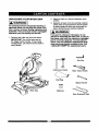
Operator's Manual
JCRHFTSMIIN°J
10 in. COMPOUND MITER SAW
WITH LASER TRAC _
Model No..137.212360
CAUTION:
Before using this Miter Saw,
read this manual and follow
all its Safety Rules and
Operating Instructions
Safety Instructions
Installation
•
For Technical
Support
Customer
Help Line
1-800-843-1682
Sears, Roebuck and Co., Hoffman
Estates, IL60179
Visit our Craftsman website: www.sears.com/craftsman
Part No. 13721236001
Operation
Maintenance
Parts List
Sears Parts &
Repair
Center
1-800-469-4663
USA
Printed in China
SECTION
PAGE
warranty ...............................................
Product Specifications ..........................
2
2
Symbols ................................................
Power Tool Safety .................................
Compound Miter Saw Safety .................
SECTION
PAGE
Know Your Compound Miter Saw ..........
Glossary of Terms .................................
10
11
3
Assembly and Adjustments ...................
12
4
6
Operation ...............................................
Maintenance ..........................................
18
23
Electrical Requirements and Safety ......
Accessories and Attachments ...............
7
8
Troubleshooting Guide ..........................
Parts List ................................................
24
25
Tools Needed for Assembly ..................
Carton Contents ....................................
8
9
Repair Protection Agreement ..................
28
CRAFTSMAN ONE YEAR FULL WARRANTY
If this Craftsman tool fails due to a defect in material or workmanship within one year from the
date of purchase, call 1-800-4-MY-HOME®to arrange for free repair(or replacement if repair
proves impossible).
This warranty applies for only90 days from the date of purchase if this product is ever used for
commercial or rental purposes.
This warranty does not includeexpendable parts, suchas lamps, batteries, bitsor blades.
This warranty gives you specific legal dghts, and you may also have other rightswhich vary from
state to state.
Sears, Roebuck and Co., Hoffman Estates, IL 60179
_i, WARNING J
Some dust created by using power tools contains chemicals known to the state of California to cause
cancer and birth defects or other reproductive harm. Some examples of these chemicals are:
•
Lead from lead-based paints
•
Crystalline silica from bricks, cement and other masonry products
•
Arsenic and chromium from chemically treated lumber
Your risk from these exposures varies, depending on how often you do this type of work. To reduce
your exposure to these chemicals, work in a well ventilated area and work with approved safety
masks that are
MOTOR
Cutting
Power Source ................ 120V AC, 60Hz, 15 Amp
Arbor Shaft Size ............ 5/8 in.
Crosscut
2-5/8
in. x 5-1/2 in.
Miter 450 R & L .................
2-5/8
in. x 3-7/8 in.
Speed ........................... 4800 RPM (No load)
Brake ............................ Electric
Double Insulated .......... No
MITER SAW
Bevel 45 ° L .......................
1-1/2 in. x 5-1/2 in.
Rotating Table:
Diameter ........................... 10 in.
Miter Detent Stops .......
Bevel Positive
Capacity:
...........................
45 ° Miter and 45 ° Bevel .... 1-1/2 in. x 3-7/8 in.
BLADE
0 °, 15 °, 22.5 °, 31.6 °, 45 ° R & L Arbor .................................
5/8 in.
Stops .... 0 °, 45 ° L
IA WARNING J
To avoid electrical hazards, fire hazards or damage to the tool, use proper circuit protection,
This tool is wired at the factory for 110-120 Volt operation. It must be connected to a 110-120
Volt / 15 Ampere time delay fuse or circuit breaker, To avoid shock or fire, replace power cord
immediately
if it is worn, cut or damaged in any way.
Before using your tool, it is critical that you read and understand
these safety rules. Failure to
follow these
2009/03
rules could result in serious
injury
n
2to--damage
-
to the tool.
I
WARNING
ICONS
Your power tool and its Operator's Manual may contain "WARNING
ICONS" (a picture symbol
intended to alert you to, and/or instruct you how to avoid, a potentially
hazardous condition).
Understanding
and heeding these symbols will help you operate your tool better and safer.
Shown below amsome
of the symbols you may see.
SAFETY
®
ALERT:
Precautions
that involve your safety.
PROHIBITION
WEAR EYE PROTECTION: Always wear safety goggles or safety glasses with side
shields.
READ AND UNDERSTAND
INSTRUCTION
MANUAL: To reduce the risk of injury,
user and all bystanders must read and understand instruction manual before using this
product,
®
KEEP HANDS AWAY FROM BLADE:
will result in serious personal injury.
SUPPORT
I,A
DANGER
IA
WARNING]
AND CLAMP
I
Failure to keep your hands away from the blade
WORK
DANGER: indicates an imminentlyhazardous situation which, if not
avoided, will result in death or serious injury.
WARNING:
indicates a potentially hazardous situation which, if not
avoided, could result in death or serious injury.
I,& CAUTION I
CAUTION: indicates a potentially hazardous situation which, if not
avoided, may result in minor or moderate injury.
I CAUTIONI
CAUTION:
hazardous
damage.
IIIIIIIII
IIIIIIIIII
IIII
used without the safety alert symbol indicates a potentially
situation which, if not avoided, may result in property
I
3
III
III
III
GENERAL
SAFETY
INSTRUCTIONS
BEFORE
USING
THIS
POWER
TOOL
Safety
isacombination
ofcommon
sense,
staying
alert
andknowing
how
touseyour
power
tool.
[_IL WARNING]
To avoid mistakes that could cause serious
Injury, do not plug the tool in until you have
read and understood the following.
1. _
READ and become familiar with the
entire Operator's Manual. LEARN
the tool's application,limitationsand
possiblehazards.
The table on page 7 shows the correct
size to use depending on cord length and
nameplate ampere rating.If in doubt, use the
next heavier gauge. The smallerthe gauge
number, the heavier the cord.
11.WEAR PROPER APPAREL. Do not wear
loose clothing,gloves, neckties, rings,
bracelets or otherjewelry which may get
caught in moving parts. Nonslip footwear is
recommended. Wear protectivehair covering
to contain long hair.
12.ALWAYS WEAR EYE PROTECTION. Any
intothe eyes and could cause
ower tool can
foreignobjects
permanent
eye throw
damage.
ALWAYS
wear Safety Goggles (not glasses)
that complywith ANSI Safety standard Z87.1.
Everyday eyeglasses have only impactresistant lenses. They ARE NOT safety
glasses. Safety Goggles are available at
Sears. NOTE: Glasses or goggles not in
compliance with ANSI 7.87.1 could seriously
injure you"when they break.
O
2. KEEP GUARDS IN PLACE and in working
order.
3. REMOVE
ADJUSTING
KEYS AND
WRENCHES.
Form the habit of checking to
see that keys and adjusting wrenches are
removed from the tool before turning ON.
4. KEEP WORK AREA CLEAN, Cluttered areas
and benches invite accidents.
5. DO NOT USE IN DANGEROUS
ENVIRONMENTS. Do not use power tools
in damp locations,or expose them to rain or
snow. Keep workarea well lit.
13.WEAR A FACE MASK OR DUST MASK.
Sawing operation producesdust.
14.SECURE
O
6. KEEP CHILDREN AWAY. All visitorsand
bystandersshould be kept a safe distance
from work area.
7. MAKE WORKSHOP CHILD PROOF with
padlocks, master switchesor by removing
starter keys.
8. DO NOT FORCE THE TOOL. It will do thejob
better and safer at the rate for which it was
designed.
9. USE THE RIGHT TOOL. Do not force the tool
or an attachment to do a job for which it was
not designed.
10.USE PROPER EXTENSION CORDS. Make
sure your extension cord is in good condition.
When using an extensioncord, be sure to use
one heavy enough to carry the current your
productwill draw. An undersizedcord will
result in a dropin line voltageand in loss of
power whichwill cause the toolto overheat.
III IIIIIIII
III
I
WORK,
Use clamps or a vise to
than using your hand and it frees
old work when practical. It is safer
both hands to operate the tool.
15.DISCONNECT TOOLS FROM POWER
SOURCE before servicing,and when
changing accessories such as blades, bits
and cutters.
16.REDUCE
THE RISK OF UNINTENTIONAL
STARTING,
Make sure switch is in the OFF
position before plugging the tool in.
17.USE RECOMMENDED
ACCESSORIES.
Consult this Operator's Manual for
recommended accessories. The use of
improper accessories may cause risk of injury
to yourself or others.
18.NEVER
STAND
ON THE TOOL.
Serious
injury could occur if the tool is tipped or if the
cutting tool is unintentionally contacted.
19.CHECK FOR DAMAGED PARTS, Before
further use of the tool, a guard or other part
that is damaged should be carefully checked
4 ---_
III
todetermine
that it will operate properly and
perform its intended function - check for
alignment of moving pads, binding of moving
parts, breakage of pads, mountingand any
other conditionsthat may affect its operation.
A guard or other part that is damaged should
be properly repaired or replaced.
20,NEVER LEAVE THE TOOL RUNNING
UNATTENDED. TURN THE POWER "OFF".
Do not walk away from a running tool untilthe
blade comes to a complete stop and the tool
is unpluggedfrom the power soume.
21,DO NOT OVERREACH. Keep proper footing
and balance at all times.
22,MAINTAIN TOOLS WITH CARE. Keep
tools sharp and clean_forbest_
performance,Follow instructionsfor
lubricatingand changing accessories,
23,WARNING: Dust generated from certain
materials can be hazardous to your health.
Always operate saw in well-ventilated area
and provide for proper dust removal.
24.1A DANGER I
People with electronic devices, such as
pacemakers, should consult their physician(s)
before using this product. Operation of
electrical equipment in close proximity to a
heart pacemaker could cause interferenceor
failure of the pacemaker.
SPECIFIC
SAFETY
INSTRUCTIONS
FOR
THIS
COMPOUND
MITER
SAW
1.
DO NOT USE THIN KERF BLADES they
can deflect and contact guard and can cause
possible injury to the operator.
stop before returningthe saw to the raised
position.
20. MAKE SURE the blade has come to a
complete stop before removingor secudng
the workpiece, changing the workpiece angle
or changing the angle of the blade.
2.
DO NOT operate the miter saw until it
is completely assembled and installed
according to these instructions.
21. NEVER cut metals or masonry productswith
thistool. This miter saw is designedfor use
on wood and wood-like products.
3.
IF YOU ARE NOT thoroughly familiar with
the operation of miter saws, seek guidance
from your supervisor, instructor or other
qualified person.
22. NEVER cut small pieces. If the workpiece
being cut would cause your hand or fingers
to be within 6-3/4 in. of the saw blade the
workpiece is too small.
4.
ALWAYS hold the work firmly against the
fence end table. DO NOT perform any
operation free hand (use clamp wherever
possible).
23. PROVIDE adequate support to the sides of
the saw table for long work pieces.
24. NEVER use the miter saw in an area with
flammable liquidsor gases.
5,
KEEP HANDS out of the path of the saw
blade. If the workpiece you are cutting would
cause your hands to be within 6-3/4 in. of the
saw blade, the workpiece should be clamped
in place before making the cut.
6.
BE SURE the blade is sharp,
is free of vibration.
7.
ALLOW the motor to come up to full speed
before starting a cut.
8.
KEEP THE MOTOR AIR SLOTS CLEAN
and free of chips or dust.
9.
ALWAYS MAKE SURE all handles are tight
before cutting, even if the table is positioned
in one of the positive stops.
25. NEVER use solvents to clean plasticparts.
Solvents could possiblydissolveor otherwise
damage the material.
26. SHUT OFF the power before servicingor
adjustingthe tool.
27. DISCONNECT the saw from the power
source and clean the machinewhen finished
using.
28. MAKE SURE the work area is clean before
leaving the machine.
runs freely and
29. SHOULD any part of your miter saw be
missing,damaged, or fail in any way, or any
electricalcomponent fail to perform properly,
lock the switch and remove the plugfrom
the power supply outlet. Replace missing,
damaged, or failed parts before resuming
operation.
10. BE SURE both the blade and the collar are
clean and the arbor bolt is tightened securely.
11. USE only blade collars specified for your saw.
12. NEVER use blades larger in diameter than
10 inches.
POWER SUPPLY AND MOTOR
SPECIFICATIONS
The AC motor used in this saw is a universal,
nonreversible type. See "MOTOR" in the
"PRODUCT SPECIFICATIONS"
section on
page 2.
13. NEVER apply lubricants to the blade when it
is running,
14. ALWAYS
check the blade for cracks or
damage before operation. Replace a cracked
or damaged blade immediately.
15. NEVER
use blades recommended
for
IA WARNINGI
operation at less than 4800 RPM.
16. ALWAYS keep the blade guards in place and
use at all times.
17. NEVER
To avoid electrical hazards, fire hazards,
or damage to the tool, use proper circuit
protection. Your saw is wired at the factory
for 120 V operation. Connect to a 120 V, 15
A circuit and use a 15 A time delay fuse or
circuit breaker. To avoid shock or fire, If
power cord is worn or cut, or damaged in any
way, have it replaced immediately.
reach around the saw blade.
18. MAKE SURE the blade is not contacting the
workpiece before the switch is turned ON.
19. IMPORTANT:
After completing the cut,
release the trigger and wait for the blade to
6
......
[....
GROUNDING
INSTRUCTIONS
NOTE: When using an extension cord on a
circuit with a #14 wire, the extension cord must
not exceed 25 feet in length. Before connecting
the motor to the power line, make sure the switch
is in the off position and the electric current is
rated the same as the current stamped on the
motor nameplate. Running at a lower voltage
will damage the motor. This tool is intended for
use on a circuit that has a receptacle like the one
illustrated in Fig. 1.
IN THE EVENT OF A MALFUNCTION
OR
BREAKDOWN,
grounding provides a path of
least resistance for electric currents and reduces
the risk of electric shock. This tool is equipped
with an electrical cord that has an equipmentgrounding conductor and a grounding plug. The
plug must be plugged into a matching receptacle
that is properly installed and grounded in
accordance with all local codes and ordinances.
Fig. 1 shows a three-pronged electrical plug and
receptacle that has a grounding conductor. If a
properly grounded receptacle is not available,
an adapter (Fig. 2) can be used to temporarily
connect this plug to a two-contact grounded
receptacle. The adapter (Fig. 2) has a rigid lug
extending from it that MUST be connected to
a permanent earth ground, such as a properly
DO NOT MODIFY THE PLUG PROVIDED.
If it will not fit the receptacle, have the proper
receptacle installed by a qualified electrician,
IMPROPER CONNECTION of the equipment
groundingconductorcan result in riskof electric
shock. The conductorwith the green insulation
(with or withoutyellowstripes) is the equipment
groundingconductor. If repairor replacement of
grounded receptaclebox.
or
IAWARNiNG
I
the equipment groundingconductorto a
oorv_'t
live terminal.
In all cases, make certain the receptacle is
properly grounded. If you are not sure, have a
qualified electrician check the receptacle.
CHECK with a qualifiedelectricianor service
person if youdo not completely understandthe
groundinginstructions,or if you are not certain
the tool is properlygrounded.
[A WARNING l
This tool is for indoor use only. Do not
expose to rain or use in damp locations.
USE onlythree-wire extensioncords that have
three-prongedgroundingplugswith three-pole
receptacles that accept the tool'splug. Repair or
replace damaged or worn cords immediately.
Fig. 1
GUIDELINES FOR EXTENSION
CORDS
Fig. 2
IIground
...-_
U/" -
III
II
_
Adapter
Two-Pronged
Receptacle
IA WARNING
[
This tool must be grounded while in use to
irotect the operator from electric shock.
iil,e] =-illi_ll r,_,_.vll
(When usin_l 120 volts only)
Use a separate electrical circuit for your tool. This
circuit must not be less than #12 wire with a 20 A
time-lag fuse or a #14 wire with a 15 A time-lag
fuse.
III
ProperlyGrounded
Three-Pronged
Receptacle
GroundingLug_
Make sure this
! I(_"l II iSconnected
_i-!.L ! "_'_l_lJ_
to a known
Make sure your extension cord is properly
wired and in good condition.Always replace a
damaged extensioncord or have it repaired by a
qualifiedtechnician beforeusing it. Protectyour
extensioncords from sharp objects, excessive
heat and damp or wet areas.
II
Plug
II'-0AJ Lrounding
Prong
USE THE PROPER EXTENSION CORD. Make
sure your extensioncord is in good condition.
Use an extensioncord heavy enough to carry
the current your productwill draw. An undersized
cord will cause a dropin line voltage resulting
in loss of power, overheating and burningout
of the motor.The table on the rightshows the
correct size to use dependingon cord length
and nameplate ampere rating.If in doubt,use
the next heaviergauge. The smallerthe gauge
number, the heavier the cord.
III
_i1 _:_:ee-Pronged
7
_e,][e,]
:k'.,5.-,[e]
-i i :[..,fzl _i elz|
RECOMMENDED
I,_
•
•
ii IVzTI,];i_v_
i:1_| i
munro_o]
nk,'ln
+l=1:lm:lntl=+o]
:ir;1.-,_-_:lm
i=]m¥_
SUPPLIED
ACCESSORIES
WARNING
NOT SUPPLIED
I
Use only accessories
recommended
for
this miter saw. Follow instructions
that
Blade Wrench
accompany
accessories.
Use of Improper
acceseorles
may cause hazards.
The use of any cutting tool except 10 in.
Adjustable Wrench
=====J
saw blades which meet the requirements
under recommended
accessories
is
:::::::::::::::::::::
Hex Key
Combination
Square
prohibited.
Do not use accessories
such
as shaper cutters or dado sets. Ferrous
metal cutting and the use of abrasive
wheels is prohibited.
•
Do not attempt to modify this tool or
create accessories
not recommended
Philips Screwdriver
for
Slotted Screwdriver
use with this tool. Any such alteration or
modification
is misuse and could result in
a hazardous
serious
condition
leading
to possible
injury.
ACCESSORIES
Visit your Sears Hardware Department or see the
Sears Power and Hand Tool Catalog to purchase
recommended accessories for this power tool.
COMBINATION
•
MUST BE TRUE
Should not gap or overlap when square is flipped
over (see dotted figure).
[A, WARNING]
•
SQUARE
To avoid the risk of personal injury, do not
modify this power tool or use accessories
Straight edge or
a 3/4 in. board,
this edge must be
perfectly straight.
Draw light line on
board along this
edge.
not recommended
by Sears.
Read warnings and conditions on your
CARBIDE TIPPED SAW BLADE. Do not
operate the saw without the proper saw
blade guard in place. Carbide is a very
hard but brittle material. Care should be
taken while mounting,
using, and storing
ji
carbide Upped blades to prevent accidental
damage. Slight shocks, such as striking
the tip while handling, can seriously
i
f
!
I
//
damage the blade. Foreign objects in the
workpiece, such as wire or nails, can also
cause tips to crack or break off. Before
using, always visually examine the blade
and tips for bent blade, cracks, breakage,
missing or loose tips, or other damage. Do
I I
L
not use if damage is suspected.
Failure to
heed safety instructions
and warnings can
result
in serious
II
Gap from untrue square when
. flipped over.
bodily injury.
8
!11
_
I
IIII
flllllllll
UNPACKING
YOURMITER
SAW
2. Place the saw on a secure stationarywork
surface.
IA WARNING I
3. Separate all parts from the packingmaterial.
Check each of the illustrationsshown below
to make certain all items are accounted for,
before discardingany packing material
To avoid injury from unexpected starting or
electrical shock, do not plug the power cord
into a source of power during unpacking and
assembly. This cord must remain unplugged
whenever you are working on the saw.
I,A WARNING
I
If any part is missing or damaged, do not
attempt to assemble the miter saw, or plug In
the power cord untll the mlssing or damaged
part Is correctly replaced. To avoid electric
shock, usa only Identical replacement parts
when servicing double insulated tools. Call
1-800-4-_AY-HOM_ for replacement parts.
1. Remove the miter saw from the carton.
iMPORTANT: Do not lift miter saw by
the trigger switch handle. It may cause
misalignment. Lift machine by the built-in
carry handle.
.._J
Hex Key
Hold-Down Clamp
Miter Table Handle
Dust Bag
Blade Wrench
Miter Saw
Batteries
Rear Extension Stay
II
III
9
IJ
IIIII
Safety Lock-Off Button
U
Cover Plate
Bevel
Positive Stop Locking Lever
Hand Hold for
Transportation
Miter Angle
Pointer
-Miter Lock Handle
ON/OFF
Arbor
Laser On/Off Switch
Latch
Bevel Lock Handle
Miter
Rear Extension Stay
Table Insert
Hand Holdfor
Transportation
10
II
COMPOUND
MITER
SAW TERMS
on machineand legible.
ARBOR LOCK - Allows the user to keep the
blade from rotating while tightening or loosening
the arbor bolt during blade replacement or
removal.
WRENCH STORAGE - Convenient storage to
prevent misplacingthe blade wrench.
BASE - Supports the table, holds accessories
and allows for workbench or leg set mounting.
ARBOR
mounted.
BEVEL LOCKING HANDLE - Locks the miter
saw at a desired bevel angle.
BEVEL CUT - An angle cut made through the
face of the workpiece.
BEVEL SCALE -To measure the bevel angle of
the saw blade 0° to 45° left.
COMPOUND CUT - A simultaneous bevel and
miter cut.
COVER PLATE SCREW - Loosen this screw
and rotate the plate for access to the blade arbor
bolt.
CROSS CUT - A cut made across the width of
the workpiece.
WOODWORKING TERMS
-
The
shaft
on which
a blade
is
FREEHAND" Performing a cut without using a
fence (guide), hold down or other proper device
to prevent the workpiece from twistingduring the
cuttingoperation.
FENCE - Helps to keep the workpiece from
moving when sawing. Scaled to assist with
accurate cutting.
LOWER BLADE GUARD - Helps protect your
hands from the blade in the raised position, it
retracts as the blade is lowered.
GUM - A stickysap from wood products.
MITER HANDLE - Used to rotate the table, and
to rotate the saw to a right or left cutting position.
KERF - The amount of material removed by
blade cut.
MITER SCALE - Measures
45 ° left and dght.
MITER CUT - An angle cut made across the
width of the workpiece.
MOUNTING
HOLES
a stable surface.
HEEL - Misalignment of the blade.
the miter angle 0 ° to
- To mount the miter saw to
RESIN - A sticky sap that has hardened.
REVOLUTIONS
PER MINUTE
(RPM) - The
number of turns completed by a spinning object
in one minute.
ON/OFF TRIGGER
SWITCH - To start the tool,
squeeze the trigger. Release the trigger to turn
off the miter saw.
POSITIVE STOP LOCKING LEVER - Locks the
miter saw at a preset positivestop for the desired
miter angle.
SAW BLADE PATH - The area of the workpiece
or table top directly in line with the travel of the
blade or the part of the workpiece which will be
cut.
STOP LATCH
- Locks the miter saw in the
lowered
position
for compact
storage
and
transportation.
SET - The distance between two saw blade tips,
bent outward in opposite directions to each other.
The further apart the tips are, the greater the set.
SWITCH
WORKPIECE - The item being cut. The surfaces
of a workpiece are commonly referred to as
faces, ends and edges.
HANDLE
- The switch handle contains
the trigger switch and
blade is lowered into
down on the handle.
upright position when
the laser on/off switch. The
the workpiece by pushing
The saw will return to its
the handle is released.
WARNING
LABELS - Read and understand for
your own safety. Make sure all labels are present
I
II
I
III
IIII III I
11
I
IIII II IIIII
I
INSTALLING
THE MITER HANDLE (FIG. A)
1. Thread the miter handle (1) into the hole (2)
located at the front of the miter table.
INSTALLING
1. Squeeze
bag(1).
2.
Fig. A
THE DUST BAG (FIG. C)
the metal collar wings (2) of the dust
Place the dust bag neck opening around the
exhaust port (3), and release the metal collar
wings.
Fig. C
IA WARNING I
To avoid injury and damage to the saw,
transport or store the miter saw with the
cutting head locked in the down position.
Never use the stop latch to hold the cutting
head in a down position
for cutting
operations.
CUTTING HEAD (FIG. B)
Raising the Cutting Head
1. Push clown slightly on the switch handle (1).
2. Pull the hold-down latch (2) out of the long slot (5)
of locking hole (3) and turn 90 ° to insert into the
short slot (6).
3. Pull up the switch handle (1) to raise to the up
position.
Fig. B
Locking Cutting Head in Down Position
When transporting or storing the miter saw, the
cutting head should always be locked in the
down position.
1. Push the switch handle (1) down to its lowest
position.
2. Pull the hold-down latch (2) out of the short slot
(6) of the locking hole (3) and turn 90 ° to insert
into the long slot (5).
IMPORTANT:
To avoid damage, never carry
the miter saw by the switch handle, the cutting
arm or the miter handle. ALWAYS use the
designated carrying handle (4).
III
IIIIIIIII
III
I
I 12
INSTALLING THE REAR EXTENSION STAY
(FIG. D)
I. Loosen the extension stay lockingscrew (I)
under the saw base (2).
2. Place the rear extension stay (3) into the
holes provided in the miter saw base. Make
sure the angle of stay is in the down position
(as shown in Fig. D) for maximum support.
3, Insert the extension stay locking screw back
to hole and tighten to hold the extension.
Fig. O
I
3
INSTALLING
THE HOLD-DOWN
CLAMP
ASSEMBLY
(FIG. E)
1. Loosen the lock knob (3) from the rear side of
the saw base (4).
2. Place the hold-down clamp assembly (1) in
one of the mounting holes (2),
3, Tighten the lock knob (3).
III
Fig.E
2
REMOVING OR INSTALLING THE BLADE
] A, WARNING]
Only use a 10-inch diameter blade.
To .avoid injury from an accidental start, make
sure the switch is in the OFF position and
plug iS not connected to the power source
outleL
Removing Blade (Fig. G, H, I)
1 Unplug the saw from the outlet.
2 Allowthe cuttinghead to riseto the upright
position. Raise the lower blade guard (1) to
the up position.(Fig. G)
3 Loosen the cover plate screw (2) with a
Phillipsscrewdriver.
4. Rotate the cover plate (3) towardsthe rear of
the tool to expose the arbor bolt (4).
5. Place the blade wrench over the arbor bolt.
Fig. G
INSERTING
AND
REPLACING
THE
LASER
BATrERIES
(FIG.
F)
• Unplug
your
miter
saw.
IAWARNING
l
Failure to unplugyour tool could result in
accidental startingcausing possibleserious
personal injury.
1. Remove the lockingscrew (1) on the
batterycover (2) with a Phillips screwdriver,
and open the cover.
2. Insert the two supplied AAA batteries in the
case as per the diagram below. If replacing
the batteries, take out the old batteries and
place with new AAA batteries. Dispose of old
batteries properly.
3. Put on the battery cover, replace the
locking screw and tightenit securely.
NOTE: Replace the batteries with batteries that
have a rating of 1.5 volts(Number 4 series and
AAA size or equivalent).
Locate the arbor lock (5) on the motor,below
the switch handle. (Fig. H)
7. Press the arbor lock, holding it in firmly
while turning the blade wrench clockwise.
The arbor lock will engage after turning the
wrench. Continueto hold the arbor lock in to
keep it engaged, while turningthe ,wrench
clockwise to loosen the arbor bolt.
6.
Fig. H
Fig, F
5
8.
I
II
Remove the arbor bolt (8), outer blade collar
(6), and the blade (7). Do not remove the
inner blade collar. (Fig. I)
13 JllllI
III
--
NOTE:
Pay
attention
tothepieces
removed,
the table and check for any contact
noting
their
position
anddirection
they
face.
the metal base or the tum table.
Wipe
theblade
collars
clean
ofanysawdust
ADJUSTMENT
INSTRUCTIONS
before
installing
thenew
blade.
IA, WARNING J
Fig.I
To avoid Injury from an accidental start, make
sure the swItch is in the OFF position and the
plug is not connected to the power source
outlet.
,7
Installing Blade (Fig. G, H, I)
1. Install a 10 in. blade with a 5/8 in. arbor
making sure the rotationarrow on the blade
matches the clockwise rotation arrow on the
upper guard, and the blade teeth are pointing
downward.
2. Place the blade collar (6) against the blade
and on the arbor. Thread the arbor bolt (4)
onto the arbor in a counterclockwisedirection.
(Fig. G) IMPORTANT: Make sure the flats of
the blade collars are engaged with the fiats on
the arbor shaft. Also, the flat side of the blade
collar must be placed againstthe blade.
3. Place the blade wrenchon the arbor bolt.
4. Press the arbor lock (5), holding it in firmly
while turningthe blade counterclockwise.
When arbor lockengages, continue to press it
in while tightening the arbor bolt securely.
(Fig. H) .
5. Rotate the cover plate (3) back to its odginal
positionuntil the slot in the cover plate
engages with the cover plate screw (2). While
holdingthe lower blade guard,tightenthe
screw with a Phillipsscrewdriver.(Fig. G)
NOTE: The lower blade guard must be raised
to the upright position to access the cover
plate screw.
6. Lowerthe blade guard (1) and verify that the
operation of the guarddoes not bind or stick.
7. Be sure the arbor lockis released so the
blade tums freely.
A
•
WARNING
AD,iUSTING FENCE SQUARENESS (FIG. J)
I. Loosen the three fence lockingbolts(I).
2. Lower the cuttingarm and lock in position.
3. Using a square, lay the heel of the square
againstthe blade, and the rule agaist the
fence(2) as shown. Check to see if the fence
is 90° to the blade.
4. If not, adjust fence 90° to the blade and
tighten the fence lockingbelts.
CAUTION: If the saw has not been used
recently, recheckblade squareness to the
fence and readjust if needed.
5. After fence has been aligned, usinga scrap
piece of wood, make a cut at 90° then
check squareness on the piece. Readjust if
necessary.
Fig. J
MITER SCALE (FIG. K)
The miter scale assists the user in setting
the desired miter angles from 45° left to 45°
right.The miter saw table has nineof the most
common angle setttingswith positive stops at
0 °, 15°, 22.5 °, 31.6°, and 45°. These positive
stopsposition the blade at the desired angle
quickly and accurately.
To Adjust the Angle:
1. Unlockthe miter table by turningthe miter
handle (1) counterclockwise.
2. Press down the positivestop lockinglever (2)
while holding the miter handle, and rotate the
table leftor rightto the desired angle.
3. Release positive stop lockinglever. Tighten
miter handle.
4. If the desired angle is one of the nine positive
stops, release the positivestop lockinglever,
making sure the lever snaps into position, and
I
To avoid Injury, never use the saw
without the cover plate secure In place. It
keeps the arbor bolt from failing out if it
accidentally loosens, and helps prevent
the splnning blade from comlng off the
saw.
•
with
Make sure the collars are clean and
propsdyarranged. Lower the blade into
14
then secure by tightening the miter handle.
5. If the miter angle desired is not one of the
nine positive stops, simply lock the miter table
into position by turning the miter handle in the
clockwise direction.
To Adjust
the Indicator:
(1) Adjust the indicator (3) to the 0 o mark on
the miter scale (4) to position the miter
table.
(2) Release positive stop locking
Tighten miter handle.
lever (2).
Fig. K
CUTTING ARM TRAVEL
Cutting Arm Downward Travel Adjustment
(Fig. L)
I A WARNING I
To avoid injury from unexpected stalling
or electrical shock, turn the switch OFF
and remove the power cord from the power
source.
BEVEL STOP ADJUSTMENT (FIG. M, N, O)
I& WARNING I
To avoid injury from unexpected starting
or electrical shock, make sure the trigger is
released and remove the power cord from the
power source.
90 ° Bevel Adjustment (Fig, M)
1. Loosen bevel lock handle (1) and tilt the
cuttingarm completelyto the right.Tighten
the bevel lock handle. Lowerblade.
2. Place a combinationsquare (2) on the miter
table with the rule againstthe table and the
heel of the square against the saw blade.
3. If the blade is not 90° square with the miter
table, loosen the bevel lock handle, tilt the
cuttinghead completelyto the left, loosen
the Iocknut(4) on the bevel angle adjustment
bolt (3) and use a 13 mm wrench to adjust
the bolt (3) in or out to increase or decrease
the bevel angle.
4. Tilt the cutting arm to back to the right at 90°
bevel and recheck for alignment.
5. Repeat steps t through 4 if further
adjustmentis needed.
6. Tighten bevel lock handle and Iocknut (4)
when alignment is achieved.
Fig. M
NOTE: Before each cutting operation, check the
positionof the blade to make sure it does not
contact any metal surface. If the blade contacts
any metal surface, the depth of travel must be
adjusted.
1. Lower the blade as far as possible.
2. Loosen the Iocknut (3).
3. Tum the adjustment bolt (4) out
(counterclockwise)to decrease the cutting
depth or in (clockwise)to increasethe cutting
depth.
4. Carefully rotate the blade manually to check
for contact. Avoid touchingblade points or
edges.
5. Repeat untiladjusted properly, and tighten
the Iocknut to secure the adjustment bolt into
position.
1
Fig. L
HI I
-
-
15_':::
.....
90 ° Bevel Indicator (Fig. N)
1. When the blade is exactly 90° to the table,
loosenthe bevel indicatorscrew (5) using a
#2 Phillipsscrewdriver.
2. Adjust bevel indicator(6) to the =0"mark (7)
on the bevel scale and retightenthe screw.
MOUNTING
THE MITER SAW (FIG. P, Q)
I A, WARNING}
To avoid injury from unexpected saw
movement:
•
Before moving the saw, disconnect the power
cord from the outlet, and lock the cutting arm
in the lower position using the stop latch.
NOTE: The stop |atch is for carrying or
storing the tool. It is not to be used for holding
the saw while cutting. Lower blade and press
in stop latch to secure saw for transport or
storage.
•
Never carry the miter saw by the power cord
or by the switch handle. Carrying the tool by
the power cord could cause damage to the
insulation or wire connections resulting in
electric shock or fire.
•
To avoid injury from flying debris, do not
allow visitors to stand behind the saw.
•
Place the saw on a firm, level work-surface
where there is room for handling and properly
supporting the workpiece.
•
Support the saw on a level work surface.
•
Bolt or clamp the saw to its support.
Fig. N
7------5/
15° Bevel Adjustment (Rg. O)
I. Unlock the bevel lock handle (1) and tiltthe
cuttingarm as far to the left as possible.
2. Usinga combinationsquare, check to see if
the blade angle is 45° to the table.
3. If the blade is not at 45° to the miter table,
tilt the cuttingarm to the right,loosen the
Iocknut(5) on the bevel angle adjustment
bolt (4) and use a 13 mm wrench to adjust
the bolt (4) in or out to increaseor decrease
the bevel angle.
4. Tilt the cuttingarm to the leftto 45 ° bevel and
recheckfor alignment.
5, Repeat steps 1 through4 untilthe blade is at
45 ° to the miter table.
6, Tighten bevel lock handle and Iocknut(5)
when alignment is achieved.
Place the saw in the desired location,either on a
work benchor recommended leg set. The base
of the saw has four mountingholes (10). (Fig. P)
Mounting instructions
1. For stationary use, place the sew in the
desired location, directly on a workbench
where there is room for handling and proper
support of the workpiece. The base of the
saw has four mounting holes. Bolt the base
of the miter saw (1) to the work surface (5),
using the fastening method as shown in Fig P.
Fig. P
Fig. 0
1.
2.
3.
4,
5.
6,
7,
8,
9,
Miter sew base
Hex head bolt
Rubberwasher
Fiat washer
Workbench
Flatwasher
Lockwasher
Hex nut
Jam nut
10
10
II
IIIIIII
II
III
16
NOTE: Mountinghardware is not includedwith
thistool. Bolts, nuts, washers, and screws must
be purchas_l separately.
2.
Laser Warning Label:
Max output <SmW DIODE LASER:
IS30-670nm, Complies with 21CFR 1040.10
and 1040. 11.
For portable use, place the saw on a 314 in.
thickpiece of plywood.Boltthe base of the
miter saw securely to the plywoodusingthe
mounting holes on the base. Use C-clamps
to clamp this mountingboard to a stable work
surface at the worksite.
AVOIOI_'T
EYEEXPO_IE OR_
_
FIADWION
DmL_TLY WfllH
0PTiCAL
Bd81RUMBMT_
Fig. Q
C_
_1_ 21CFR10S.10I',d 10W.ll
Cl*n k L_er Produd •
\._
I& WARNING I
Inch Plywood
•
IA
•
Hand Hold for
Transportation
•
/
THE LASER GUIDE (RG. R)
1. To turn laser on, tum switch(1)to "1"position.
2. To turn laser off, turn switchto "O" position.
Use of controls or adjustments or
performance of procedures other than
those specified herein may result in
hazardous radiation exposure.
WARNING
J
The use of optical Instruments with this
product will increase eye hazard.
Do not attempt to repair or disassemble
the laser. If unqualified persons attempt
to repair this laser product, serious injury
may resuIL Any repair required on this
laser product should be performed by a
Sears or other qualified service center.
NOTE: All the adjustments for the
operation of this machine have been
completed st the factory.
Fig. R+
Your tool is equipped with the Laser Guide
usinga Class III laser beam. The laser beam will
enable you to preview the sew blade path on
the stock to be cut beforestartingthe miter saw.
This laserguide is powered by two AAA 1.5 volt
batteries.
AVOID DIRECT EYE CONTACT
A
•
WARNING
I
Laser is radiated when laser guide is
turned on. Avoid direct eye contact.
Always un-plug the miter sew from power
source before making any adjustments.
17
IIIIII
SAFETY
INSTRUCTIONS
FOR BASIC SAW
saw is missing,bent, damaged or broken in
any way, or any electricalparts don't work,
turn the saw off and unplugit.
Replace bent, damaged, missingor defective
parts beforeusing the saw again.
Maintaintools with care. Keep the miter
saw clean for best and safest performance.
Follow instructionsfor lubricating.Do not put
lubricantson the blade while it is spinning.
Remove adjusting wrenchfrom the toot before
turning it on.
To avoid injury from jams, slips, or thrown
pieces, use only recommendedaccessories_
Check the dust bag before you work. Empty
the bag if it is more than half-fulL
OPERATION
BEFORE USING THE MITER SAW
•
[_
•
WARNING]
To avoid mistakes that could cause serious,
permanent injury, do not plug the tool in until
the following steps are completed:
• Completely assemble and adjUstthe saw,
followingthe instructions.(ASSEMBLY AND
ADJUSTMENTS)
• Learn the use and functionof the ON/OFF
switch, lock-off switch, upperand lower blade
guards, hold down latch; bevel lock handle
and cover plate screws.
• Review and understand all safety instructions
and operating procedures in thisOperator's
Manual. (SAFETY & OPERATIONS)
• Review the MAINTENANCE and
TROUBLESHOOTING GUIDE foryour miter
,
•
•
•
RECOMMENDED ACCESSORIES
•
Consult the ACCESSORIES and
ATTACHMENTS sectionof this Operators
Manual for recommendedaccessories. Follow
the insb'uctionsthat come with the accessory,
The use of improperaccessories may cause
riskof injuryto persons.
Choose the correct 10 in. diameter blade for
the material and the type of cuttingyou plan
to do. Do not use thin kerf blades.
Make sure the blade is sharp, undamaged
and properly aligned.With the saw
unplugged,push the cuttingarm all the way
down. Manually spinthe blade and check for
clearance. Tilt the power-head to a 45° bevel
and repeat the,test.
Make sure the blade and arbor collarsare
clean.
Make sure all clamps and locks are tightand
there is no excessive play in any parts.
saw,
•
To avoid injuryor possibledeath from
electricalshock:
Make sure your fingersdo not touch the
plug'smetal prongswhen pluggingor
unpluggingyour miter saw. (ELECTRICAL
EQUlREMENTS AND SAFETY)
•
•
BEFORE EACH USE INSPECT YOUR SAW.
•
•
•
•
•
•
II
•
Disconnect the miter saw, To avoid injury
fromaccidental starting,unplugI_ saw
before any adjustments, includingset-up and
blade changes.
Compare the direction of rotation arrow
on the guard tothe directionarrow on the
blade. The blade teeth should always point
downward at the front of the saw.
Tighten the arbor bolt,
Tighten the cover plate screw,
Check for damaged parts. Check for: •
• Alignment of moving parts
• Damaged eleCtriccords
• Binding of moving parts
• Mounting holes
• Function of arm return springand lower
guard: Push the cuttingarm all the way
down, then let it rise untilit stops. The
lower guard shouldfully close. Follow
instructionsin TROUBLESHOOTING
GUIDE for adjUstment if necessary.
• Other conditionsthat may affect the way
the miter saw works.
Keep all guards in place, in workingorder and
proper adjustment! If any part of this miter
III
•
KEEP YOUR WORK AREA CLEAN
Cluttered areas and benches invite accidents.
l_,
WARNING]
To avoid burns or other fire damage, never
use use the miter saw near flammable liquids,
vapors, or gases.
• Plan ahead to protectyour eyes, hands, face
and ears.
• Know your miter saw. Read and understand
thisOperator,s Manual and labels affixed to
this tool. Learn its application and limitations
as well as the specificpotential hazards
peculiarto this tool.To avoid injuryfrom
accidentalcontact with moving parts, do not
do layout,assembly, or setup workon the
miter saw while any parts are moving.
• Avoidaccidental starting,make sure the
trigger switch is disengaged before plugging
the miter saw into a power outlet.
18
II III
IIII
I1'
I
I'111111
IIq]
PLAN YOUR WORK
• Use the right tool. Don't force a tool or
attachment to do a job it was not designed
to do. Use a differenttool for any workpiece
that can't be held in a solidly braced, fixed
position.
LA CAUTION
I
This machine is not designed for cutting
masonry, masonry products, ferrous metals
(steel, iron, and iron-based metals.) Use
this miter sew to cut only wood, woodlike products, or non-ferrous metals. Other
material may shatter, bind the blade, or create
other dangers. Remove all nails that may be
in the workpieee to prevent sparking that
could cause a fire, Remove dust bag when
cutting non-ferrous metals.
•
•
•
•
Make sure there are no gaps between the
workpiece, fence and table that will let the
workplace shift after it is cut.
Keep the cut off piece free to move sideways
after it is cut off. Otherwise, it could get
wedged against the blade and thrown
violently.
Only the workpiece should be on the saw
table.
Secure work. Use clamps or a vise to help
hold the work when it's practical.
USE EXTRA CAUTION WITH LARGE OR ODD
SHAPED WORKPIECES.
• Use extra supports(tables, sawhorses,
blocks, etc.) for workpieces large enough to
tip.
• Never use another person as a substitute for
a table extension, or as an additional support
for a workpiece that is longer or wider than
the basic miter saw table, or to help feed,
support, or pull the workpiece.
• Do not use this saw to cut small pieces. If the
workpiece being cut would cause your hand
or fingers to be within 6-3/4 inches of the saw
blade the workpiece is too small. Keep hands
and fingers out of the "no hands zone" area
marked on the saw table.
• When cuttingodd shaped workpieces, plan
your work so it will not bind in the blade and
cause possible injury. Molding, for example,
must lie flat or be held by a fixture or jig that
will not let it move when cut.
• Properly support round material such as
dowel rods, or tubing, which have a tendency
to roll when cut, causing the blade to "bite".
DRESS FOR SAFETY
Any power tool can throw foreign
objects into the eyes. This can result in
permanent eye damage. Everyday
eyeglasseshave onlyimpact resistantlenses and
are not safety glasses. Glasses or goggles not
in compliancewith ANSI Z87.1 could seriously
injure youwhen they break.
• Do not wear loose clothing,gloves, neckties
or jewelry (rings,watches). They can get
caught and draw you into moving parts.
• Wear non-slipfootwear.
• Tie back long hair.
• Roll longsleeves above the elbow.
• Noise levelsvary widely. To avoid possible
hearing damage wear ear plugs when using
any miter saw.
• For dustyoperations, wear a dust mask along
with safety goggles.
1_, WARNING
INSPECT YOUR WORKPIECE
Make sure there are no nails or foreign objects in
the part of the workpiece beingcut.
Plan your work to avoid small pieces that may
bind,or that are too small to clamp and get a
solidgrasp on.
Plan the way you will grasp the workpiece from
start to finish. Avoidawkward operationsand
hand positions.A sudden slip could cause your
fingers or hand to move into the blade.
To avoid injury, follow all applicable safety
instructions, when cutting non-ferrous
metals:
• Use only saw blades specifically
recommended for non-ferrous metal cutting.
• Do not cut metal workpieces that must be
hand held. Clamp workpieces securely.
• Cut non-ferrous metals only if you are under
the supervision of an experienced person and
the dust bag has been removed from the saw.
DO NOT OVER-REACH
Keep good footing and balance. Keep your face
and body to one side, out of the line of a possible
kickback. NEVER stand in the line of the blade.
Never cut freehand:
• Braceyour workpiece firmlyagainst the fence
and table stopso it will not rock or twist during
the cut.
• Make sure there is no debris between the
workplace and the tableor fence.
!
]
WHEN SAW IS RUNNING
J_
WARNING
Do not allow familiarity from frequent use of
your miter sew to result in a careless mistake.
A careless fraction of a second is enough to
cause a severe injury.
Before cutting, if the saw makes an unfamiliar
noise or vibrates, stop immediately. Turn the
sew OFF. Unplug the sew. Do not restart until
finding and correcting the problem.
BODY AND
HAND POSITION
WARNING
(FIG. S)
I
area. Proper positioning of your body
Never
place when
handsoperating
near the the
cutting
and hands
miter
saw will make cutting easier and
safer. Keep children away. Keep all visitors
at a safe distance from the miter saw. Make
sure bystanders are clear of the saw and
workpiece, Don't force the saw. It will do the
job better and safer at its designed rate.
Starting a cut:
• Place hands at least 6-3/4 in. away from the
path of the blade - out of the "no-hands zone"
(1). (Fig. S)
• Hold workpiece firmly against the fence to
prevent movement toward the blade.
• With the power switch OFF, bring the saw
blade down to the workpiece to see the
cutting path of the blade.
• Press in lock-off switch in trigger switch
handle,
• Squeeze trigger switch to start saw.
• Lower blade into workpiece with a firm
downward motion.
Finishing a cut:
• Hold the cutting arm in the clown position.
• Release trigger switch and wait for all moving
parts to stop before moving your hands and
raising the cutting arm.
• If the blade doesn't stop within 6 seconds,
unplug the saw and follow the instructions in
TROUBLESHOOTING
GUIDE section.
Before freeing jammed material:
• Release trigger switch.
• Wait for all moving parts to stop. "
• Unplug the miter saw,
1
Fig
TURNING SAW ON (FIG. T)
To reduce the likelihood of accidental starting, a
thumb activated lock-OFF switch is located on
top of the switch handle. The lock-OFF switch (1)
must be pushed in before the trigger switch (2)
can be activated and the miter saw started.
WARNING I
Make the switch child-proof,
Insert a padlock
through the hole (3) in the trigger switch and
lock it. This will prevent children and other
unauthorized
users from engaging the trigger
switch ON.
Fig. T
BEFORE LEAVING THE SAW
• Never leave tool runningunattended.Turn
power OFF. Wait for all moving parts to stop
and unplugunit from power source.
• Make workshopchild- proof. Lockthe shop,
Disconnect master switches.Store tool away
from children and other unqualifiedusers.
MITER CUT (FIG. U)
1. When a miter cut is required, unlock the
miter table by turning the miter handle (1)
counterclockwise.
2. While holding the miter handle, press down
on the positive stop locking.lever (2) to
disengage the positive stop locking lever.
3. Rotate the miter table to the right or left with
the miter handle.
4. When the table is in the desired position as
shown on the miter scale (3), release the
positive stop locking lever handle and tighten
the miter handle. The table is now locked at
the desired angle. Positive stops are provided
at 0°,15 °, 22.5 ° , 31.6 ° and 45 ° .
IMPORTANT:
ALWAYS TIGHTEN the miter
table lock handle before cutting.
Fig. U
:
6-3/4 in.
' ?' _
6-3/4
in.
2
q]
__
2O
BEVEL
CUT
(FIG.
V)
Fig. X
1. When a bevel cutis required, loosenthe bevel
lock handle (1).
2. Tilt the cuttinghead to the desired angle as
shown on the bevel scale (2), The blade can
be positionedat any angle, from a 90° straight Hold-Dow_
cut (0 ° on the scale) to a 45 ° left bevel.
3. Tighten the bevel lock handle (1) to lockthe
cuttinghead in position.
4. Positive stopsare providedat 0° and 45 °.
Clamp
Fig.
COMPOUND CUT (FIG. W)
A compound cut is the combinationof a miter
and a bevel cut simultaneously.
1. Loosen the bevel lock handle (1) and position
the cuttinghead at the desired bevel position.
Lockthe bevel lock handle.
2. Loosen the miter table lock handle (2). Press
down the positivestop lockinglever (3)
and positionthe table at the desired angle.
Release the positivestoplocking leverand
lock the miter handle.
Fig. W
_
Workpi_
CUTTING BASE MOLDING (FIG. Y)
Base moldings and many other moldings can
be cut on a compound miter saw. The setup of
the saw depends on moldingcharacteristicsand
application,as shown.
Perform practice cutson scrap material to
achieve best results:
1. Always make sure moldings rest firmly against
fence and table. Use hold-downor C-clamps,
whenever possible,and place tape on the
area being clamped to avoid marks.
2. Reduce splinteringby taping the cut area prior
to making cut. Mark cut line directly on the
tape.
3. Splinteringtypically happens due to wrong
blade applicationand thinness of the material.
Fig. Y
Workpiece
e
Miter Saw Table
I Miter Saw Table
I
m_r at 45°, beret at 0° miter at 0o,bevel at 45o
"
1
NOTE: Always perform a dry run cut so you can
determine if the operation being attempted is
possible before power is applied to the saw.
CUTTING CROWN MOLDING (FIG. Z, AA )
CUTTING BOWED MATERIAL (FIG. X)
A bowed workpiece must be positioned against
the fence and secured with a clamping device as
shown before cutting. Do not position workpiece
incorrectly or try to cut the workpiece without the
support of the fence. This will cause the blade to
bind and could result in personal injury.
I
II!1111
IHIIII
Your compound miter saw is suited for the
difficulttask of cuttingcrown molding.To fit
propedy, crown molding must be compoundmiterd with extreme accuracy.
__
.
The two surfaces or1a piece of crowT_molding
that fitflat against the ceiling and wall are at
angles that, when added together equal exactly
90 ° ,
Most crown molding has a top rear angle [the
section that fits flat against the ceiling) of 52 °
and a bottom rear angle (the section that fits fiat
against the wall) of 38 ° .
21 IIIIIIIIIII II
IIIIII
NOTE: The chart below references a
compound cut for crown molding ONLY
WHEN THE ANGLE BETWEEN THE WALLS
EQUALS EXACTLY 90°.
In order to accurately cut crown molding for
a 90 ° Inside or outside corner, lay the molding
with its broad back surfaceflat on the saw table.
When setting the bevel and miter angles for
compoundmiters, rememberthat the settingsare
interdependent;changing one changes the other,
as well.
I BEVEL I
MITER
SETTING
Fig. Z
IL
33.9°
TYPE OF CUT
31.6 ° Right 1. Position top of molding _gatnst
fence.
2. Miter table set at RIGHT 31,6 °,
3. LEFT side is finished piece.
_ble
I
IR
33,9°
31,6 ° Left 1, Position bottom of molding
ngalost 1enos,
2. Miter table set at LEFT 31.6 °,
3, LEFT side is finished piece.
Outside €omer-L_t side
Bevel/Miter Settings
O!_
33.9°
31,6 ° Left 1. Position bottom of molding
against fence.
Rg. AA
2. Miter table set at LEFT 31.6 °.
Settings for standard crown molding lying flat on
compound miter saw table
OR
33.9°
31,S o R_ht 1. Positiontop of mddldg against
fence.
Inside Corner
2. Miter table set at RIGHT 31.6° ,
L RIGHT side is finished piece.
Outside Comer
I
22
MAINTENANCE
A
LOWER BLADE GUARD
Do not use the saw without the lower blade
guard. The lower blade guard is attached to the
saw for your protection. Should the lower guard
become damaged, do not use the saw untilthe
damaged guard has been replaced. Develop a
regular check to make sure the lower guard is
working propedy.Clean the lower guard of any
dust or buildup with a damp cloth.
DANGER I
To avoid injury, never put lubricants on the
blade while it is spinning.
WARNING I
To avoid fire or toxic reaction, never usa
gasoline, naphtha acetone, lacquer thinner or
similar highly volatile solvents to clean the
miter saw.
!_
CAUTION: Do not use solventson the guard.
The)/could make the plastic "cloudy_ and brittle.
WARNING
I,A WARNING
To avoid injury from unexpected starting
or electrical shock, unplug the power cord
before workin9 on the saw.
I_
WARNING
I
When cleaning the lower guard, unplug the
saw from the power source receptacle to
avoid unexpected startup.
I
EMPTYING SAWDUST BAG
Periodically,sawdust will accumulate under the
work table and base. This couldcause difficulty
in the movement of the worktablewhen setting
up a miter cut. Frequently blow out or vacuum up
the sawdust.
For your safety, this saw is doubis-insulsted.
To avoid electrical shock, fire or Injury, use
only parts identical to those identified in the
parts list. Reassemble exactly as the original
assembly to avoid electrical shock.
IA WARNING I
REPLACING
CARBON BRUSHES (FIG. BB)
Replace both carbon brushes when either has
less than 1/4 in. length of carbon remaining, or
if the spring or wire is damaged or burned. To
inspect or replace brushes, first unplug the saw.
Then remove the black plastic cap (1) on the
side of the motor (2). Remove the cap cautiously,
because it is springloaded. Then pull out the
brush and replace. Replace for the other side.
To reassemble reverse the procedure, The ears
on the metal end of the assembly go in the same
hole the carbon part fits into, Tighten the cap
snugly, but do not overtighten.
If blowing sawdust, wear proper eye
protection to keep debris from blowing into
eyes.
LUBRICATION (FIG. CC)
All the motor bearings in thistool are lubdcated
with a sufficientamount of high grade lubricant
for the life of the unit under normal operating
conditions;therefore, no furtherbearing
lubricationis required.
Lubricatethe followingas necessary:
Chop pivot: Apply light machineoil to points
indicated in illustration.
NOTE: To reinstall the same brushes,first make
sure the brushes go back in exactlythe way they
came out. This will avoid a break-in periodthat
reduces motor performance and increases wear.
Chop and Central pivot: Applylight machine oil
to points indicated in illustration.
Fig. CC
Fig. BB
Central pivot
of plastic,
Chop
III
23
pivot
III
[_
WARNING]
To avoid injury from accidental starting, always turn switch OFF and unplug the tool before
moving, replacing the blade or making adjustments,
TROUBLESHOOTING GUIDE - MOTOR
PROBLEM
PROBLEM CAUSE
SUGGESTED CORRECTIVE ACTION
Brake does not 1. Motorbrushes not sealed or lightly 1. Inspect/clean/replacebrushes. See
MAINTENANCE section.
stopthe blade
sticking.
within6 seconds. 2. Motor brake overheatedfrom use 2. Use a recommendedblade. Let cool
down, See REMOVING OR INSTALUNG
of defectiveor wrong size blade
THE BLADE sectioh.
or rapid ON/OFF cycling.
3. Arbor bolt loose.
3. Retighten. See REMOVING OR
4. Brushescracked, damaged, etc.
INSTALLING THE BLADE section.
5. Other.
4. Replace brushes.
5. Contact Sears ServiceCenter.
Motor does not
1. Limit switchfailure
1. Replace limitswitch.
start
2. Brush worn.
2. Replace brushes. See MAINTENANCE
3. Fuse blown or circuitbreaker
section.
tripped on home panel.
3. Vedfy there is electricalpower at the
outlet,
B,rush spark
1. Brush worn.
1. Replace Brushes. See MAINTENANCE
when switch
2. Other.
section.
released.
2. Contact Sears ServiceCenter.
TROUBLESHOOTING
GUIDE - sAw
OPERATION
PROBLEM
PROBLEM CAUSE
Biade hitstable. il Misalignment.
_,ngle of cut not
accurate. Can
not adjust miter.
SUGGESTED CORRECTIVE ACTION
1. See ADJUSTMENT - CuttingHead
DownwardTravel Adjustmentsection.
1. See OPERATION - Miter Angle
Adjustmentsection,
2. Vacuumor blowout dust.WEAR EYE
PROTECTION.
1. Contact Sears Service Center,
1. Miter table unlocked.
i2. Sawdust under table.
ICutting arm
Nobbles.
il.
Cutting ar_n will
=not fully #aise,
or blade guard
iwon't fully close.
Blade binds,
ams, bums
wood.
1, Pivot bolttoo tight.
1.
2. Pivot springnot replaced properly
after service.
2.
3. Sawdust build-up.
3,
1. Improperoperation.
1.
2. Dull or warpedblade.
2.
3. Improperblade size.
3.
4 Wood is moving during cut.
4.
Saw vibrates or
shakes.
1. Saw blade not round / damaged / 1. Replace blade.
loose,
2. Tighten arbor bolt.
2. Arbor Ix)it loose.
TROUBLESHOOTING
Loose pivot points.
GUIDE - LASER
Loosen pivotbolt lock nut (see adjustment
section).
Contact Sears Service Center.
Clean and lubricate rnovin9 parts.
See BASIC SAW OPERATION section.
Replace or sharpen blade.
Replace with 10in, diameter blade,
Use holddown clamp to secure workpiece
to table.
GUIDE
PROBLEM
PROBLEM CAUSE
SUGGESTED
The laser guide
fails to turn on,
1. The batteries are dead.
2. The batterycontactsneed
adjustment.
1. Replace with new AAA batteries.
2. Reload the batteries and make certain
that they make solid contact to the battery
spring.
IIIill
IIIII!1111
I
III
24
CORRECTIVE
ACTION
II
IIII
10 in. COMPOUND
MITER
SAW
MODEL
NO. 137.212360
ill WARNING l
When servicing use only CRAFTSMAN replacement parts. Use of any other parts many create
a HAZARD or cause product damage. Any attempt to repair or replace electrical parts on this
Miter Saw may create a HAZARD unless repair is done by a qualified service technician. Repair
service
is available
PARTS
LIST FOR SAW SCHEMATIC
LD.
Description
X3P1
COMPRESSION
t X3P2
BUTTON
at your nearest
Sears Service
Size
I.D.
Description
1
X3RT
COIL
1
X3RU
PLASTIC
2
X3RV
LOCK
1
X3S0
FLAT WASHER
QTY
SPRING
SWITCH
Centre.
Slze
SPRING
QTY
1
SLEEVE
1
NUT
M10
1
¢10
2
X3P4
BATTERY
X3P9
POWER
X3PA
SEGMENT
1
X3S2
POINTER
X3PC
MOTOR
HANDLE
(TOP)
1
X3S6
CR,
X3PD
MOTOR
HANDLE
(DOWN)
1
X3S7
SPRING
X3PE
CORD
CLAMP
1
X3S8
POINTER
X3PG
CORD
GUARD
1
X3SD
REAR
X3PH
LIMIT
SWITCH
1
X3SE
CR.
X3PJ
HEX,
HD.
1
X3SF
BOLT
X3PY
CUTTER
1
X3$G
FLAT
X3Q0
CR.
1
X3SH
SPRING
X3QI
SPRING
GUARD
1
X3SJ
FENCE
X:3Q3
CR.
RE.
PAN HD.
M5"6
4
X3SK
MITER
LOCK
X3Q4
CR.
RE. COUNT
M6"12
1
X3SM
FLAT
WASHER
X3Q5
RUBBER
1
X3SN
SPRING
X3Q6
COLLAR
1
X3SP
CR.
X3Q7
LOWER
!
X3SQ
SLIDE
X3Q8
BRACING
1
X3SS
BASE
X3Q9
COLLAR
1
X3ST
HEX.
X3QA
LOCK
M6
1
X3T0
MOTOR
X3QB
CR,
M6"12
1
X3T1
LASER
ASS'Y
X3OC
COLLAR
1
X3T2
BEVEL
LOCK
X3QD
FLAT
2
X3T3
ANGLE
REGULATOR
XSQW
CR.
i
X3T4
HOLD
X3R7
TRIGGER
1
X3T6
INSTRUCTION
X3R8
BLADE
1
X3T8
BEVEL
X3R9
ARBOR
2
X3T9
ROLLER
X3RA
ARBOR
1
X3TA
CR. RE PAN HD TAPPING
SCREW
M6"18
2
X3RB
BLADE
1
X3TB
CR. RE, PAN HD. TAPPING
SCREW
M4"16
8
X3RG
SHAFT
!
X3TC
CR.
M5"40
2
X3RH
TORSION
1
X3TF
RETAINING
X3RK
CR.
M5"10
1
X3TG
DUST
X3RL
HEX.
M8"20
2
X3TH
LEVER
X3RM
NUT
M8
2
X3TJ
PIVOT
X3RN
LOCK
NUT
M8
1
X3TL
CR.
X3RP
FLAT
WASHER
s8
!
X3W4
LABEL
1
X3RQ
TABLE
1
X3W9
SCALE
1
X3RR
CR,
4
X3WA
LABEL
1
X3RS
TABLE
1
X3WB
HEX
......
CABLE
HANDLE
BOLT
M6"14
SHAFT
GUARD
RE. COUNT
HD.
SCREW
SCREW
HD.
SCREW
M6"10
BLOCK
BLADE
GUARD
PLATE
NUT
RE.
PAN HD.
SCREW
WASHER
RE,
s6
COUNT
HD.
SCREW
COLLAR
BOLT
M8"20
WRENCH
SPRING
RE. PAN
HD.
HD.
SCREW
BOLT
INSERT
RE. COUNT
HD,
SCREW
M4"8
. .....
. _ 25
RE
1
PAN
HD.
SCREW
WASHER
M4"10
3
04
1
1
EXTENSION
RE. PAN
HD,
STAY
SCREW
1
M6"16
1
CLAMP
M6"14
1
WASHER
08
3
s8
3
WASHER
1
HANDLE
1
WASHER
RE,
PAN
HD,
SCREW
04
1
05
2
M5"12
2
PLATE
3
1
HD. BOLT
M8"30
ASS'Y
DOWN
1
1
HANDLE
CLAMP
ASS'Y
1
ASS'Y
1
ASS'Y
I
MANUAL
1
BOLT
M10"50
1
2
RE. PAN
HD,
SCREW
RING
2
BAG
1
1
SHAFT
RE, PAN
KEY
..................
4
HD,
SCREW
M10"55
1
M4"8
1
1
10 in. COMPOUND
SCHEMATIC
MITER
MODEL
SAW
NO, 137.212360
FOR SAW
'\,
)
X3T1
X3R9
X3RA
X3RB
(3TO
X3WB
X3T2
X3Q1
X3T_
X3RR4
-X3RS
X3SM
X3RT
X3SS
X3ST
.....
26 ......
10 in. COMPOUND
PARTS
MITER SAW
LIST AND SCHEMATIC
MODEL NO. 137.212360
FOR MOTOR
I.D.
X3P0
Description
HEX. SOC. HD. CAP SCREW
X3PK
Size
OTY
1
I.D.
X3QJ
Description
LABEL
LABEL
1
X3QK
BRUSHASS'Y
X3PL
BRUSHHOLDER ASS'Y
2
X3QL
FLOW GUIDE
]
X3PM
BRUSHCOVER
2
X3QM
CR. RE.PAN HD. TAPPING SCREW ST5"65
2
X3PQ
MOTOR HOUSING
1
X3QN
FIELDASS'Y
I
X3PR
BEARING
I
X3QU
HEX. SOC. HD. CAP SCREW
X3PS
SPRING
I
X3QR
HEX. SOC. HD. CAP SCREW
I
X3PT
ARMATURE ASS'Y
I
X3QS
ANCHOR BLOCK
I
X3PU , COMPRESSION SPRING
I
X3QY
NEEDLEBEARING
X3PV
I
X3R3
CR. RE. PAN HD. SCREW
M5"16
X3PW BEARING
I
X3SB
FLATWASHER
_5
2
X3PX
ARM
I
X3SN
SPRING WASHER
_5
4
X3PZ
FLATWASHER
4
X3TD
CR. RE. PAN HD. SCREW
M6"35
4
X3QE
RUBBERINSERT
1
X3TE
TOOTH WASHER
e4.2
I
X3QF
CAP
I
X3TM
CR. RE. PAN HD. SCREW
M4"10
I
×3QG
LABEL
1
X3WC
CUTTERSHAFTASS'Y
X3QH
LABEL
1
ARBOR LOCK
_6
OTY
Size
1
2
M6"25
i
I
2
I
_/X3PK
X3PQ_
X3PL2
X3PR
_
X3PS
_
X3PM2
'%3pz_X3TD4
X3SN
X3QM
X3QK
IIIIIIIIIII27 IIII
I
III
IIIIIII
Congratu/ations on making a smart purchase. Your new Craftsman_ product is designed and
manufactured for years of dependable operation. But like all products, it may require repair
from time to time. That's when having a Repair Protection Agreement can save you money and
aggravation.
Here's
[]
[]
[]
[]
[]
what the Repair
Protection
Agreement*
includes:
Expert service by our 10,000 professionalrepairspecialists
Unlimited service and no charge for parts and labor on all covered repairs
Product replacement up to $1500 if your covered product can't be fixed
Discount of 10% from regular pdce of service and related installedparts not covered by the
agreement; also, 10% off regular price of preventivemaintenance check
Fast help by phone - we call it Rapid Resolution- phone supportfrom a Sears representative.
Think of us as a "talking owner's manual."
Once you purchase the Repair ProtectionAgreement, a simple phone call is all that it takes for you
to schedule service. You can call anytime day or night,or schedulea service appointmentonline.
The Repair ProtectionAgreement is a risk-free purchase. If youcancel for any reason dudngthe
productwarranty period, we will provide a full refund. Or, a prorated refund anytimeafter
the product warranty period expires. Purchase your Repair ProtectionAgreement todayl
Some limitations and exclusions apply. For prices and additional information in the U.S.A.
call 1-800-827-6655.
*Coverage in Canada varies on some items. For full details cell Sears Canada at
1-600-361-6665.
Sears Installation Service
For Sears professionalinstallationof home appliances, garage door openers, water heaters, and
other major home items, in the U.S.A. or Canada call 1.600-4-MY-HOME _.
IIII
'1
I
III
III
I
28
IIIIIII
Your Home
For expert troubleshooting and home solutions advice:
manage
home
www.managemyhome.com
For repair - in your home - of all major brand appliances,
lawn and garden equipment, or heating and cooling systems,
no matter who made it, no matter who sold ,t!
For the replacement parts, accessories and
owner's manuals that you need to do-it-yourself.
For Sears professional installation of home appliances
and items like garage door openers and water heaters.
1-800-4-MY-HOME®
Call anytime, day or night
(1-800-469-4663)
www.sears.com
(U.S.A.
and Canada)
www.sears.ca
Our Home
For repair of carry-in items like vacuums, lawn equipment,
and electronics, call anytime for the location of the nearest
Sears Parts & Repair Service Center
1-800-488-1222
(U.S.A.) 1-800-469-4663
(Canada)
www.sears.com
www.sears.ca
To purchase a protection agreement on a product serviced by Sears:
1-800-827-6655
(U.S.A.)
Para pedir servicio de reparaci6n
a domicilio,y para ordenar piezas:
1-888-SU-HOGAR_
1-800-361-6665
Au Canada pour service en franc_.ais:
1-800-LE-FOYER Mc
(1-800-533-6937)
(1-888-784-6427)
www.sears.ca
oSears
©Sears
Brands,
® Registered
LLC
Trademark
® Marca Registrada
_c Marque
/
TM
de commerce
/
TM
Trademark
/ sM Service Mark of Sears Brands, LLC
Marca de Fdbrica / sM Marca de Servicio de Sears Brands,
/ _ Marque d(_posee de Sears Brands,
(Canada)
LLC
LLC