1
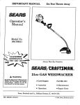
Operator's Manual
CRRFTSMRN
31 cc/2-Cycle/210 MPH
GAS POWEREDBLOWER/VAC
Model No,
316.797210
• Safety
• Assembly
• Operation
• Maintenance
• Parts List
• Espa6ol
_
Save this manual
Before
using this product,
ARNING:
read this manual and follow
for future reference.
all its Safety Rules and Operating
Instructions.
Sears, Roebuck, and Co., Hoffman Estates, IL 60179
OPERATOR'SMANUAL PARTNO. 1B2522
PRINTED IN U.S.A.
USA
Rev. B
9/99 17431)
Warranty Statement
2
Service and Adjustments
16
Safety Rules
2
Storage
17
Accessories or Attachments
6
Specifications
17
Assembly
Operation
6
9
Troubleshooting
Parts List
18
19
EspaSol
22
Maintenance
FULL
TWO
14
YEAR
WARRANTY
ON CRAFTSMAN
® GAS-POWERED
BLOWER
AND
BLOWER/VAC
For two (2) years from the date of purchase, when this Craftsman Gas-Powered Slower or BlowerNac is maintained,
lubricated and tuned up according to the operating and maintenance instructionsin the operator's manual, Sears will repair,
free of charge, any defect in materials or workmanship,
This warranty excludes blower tubes, spark plug, and air filter, which are expendable parts and become worn during normal
use.
If this blower is used for commercial purposes, this warranty applies for 90 days from the date of purchase.
If this blower is used for rental purposes, this warranty applies for 30 days from the date of purchase.
This warranty applies only while this product is in use in the United States.
WARRANTY SERVICE IS AVAILABLE BY RETURNING THE BLOWER OR BLOWERNAC
SERVICE CENTER IN THE UNITED STATES.
TO THE NEAREST SEARS
This warranty gives you specific legal rights, and you may also have other rights which vary from state to state.
Sears, Roebuck and COo,1:)/817 WA, Hoffman Estates, IL 60179
California
Proposition
65 Warning:
from this product contains chemicals
known to the state of California to
cause cancer, birth defects or other
reproductive harm.
WARNING: Theengine
exhaust
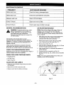
NOTE: For users on U.S. forest land and in the states of
California, Maine, Oregon, and Washington: All U.S.
forest land and the state of California (Public Resources
Codes 4442 and 4443), Oregon and Washington require,
by law that certain combustion engines operated on
forest brush and/or grass-covered areas be equipped
with a spark arrestor, maintained in effective working
order, or the engine be constructed, equipped and
maintained for the prevention of fire. Check with your
state or Iocat authorities for regulations pertaining to
these requirements. Failure to follow these requirements
could subject you to liability or a fine. This unit is factory
equipped with a spark arrestor.
-2-
SPECIAL NOTE: exposure to vibrations through
prolonged use of gasoline powered hand tools could
cause blood vessel or nerve damage in the fingers,
hands, and joints of people prone to cimulation disorders
or abnormal swelling. Prolonged use in cold weather has
been linked to blood vessel damage in otherwise healthy
people. If symptoms occur such as numbness, pain, loss
of strength, change in skin color or texture, or loss of feeling in the fingers, hands or joints, discontinue use of this
tool and seek medical attention. An anti-vibration system
does not guarantee the avoidance of these problems.
Users who operate power tools on a continual and
regular basis must monitor closely their physical
condition and the condition of this tool.
WARNING: Failure to obey a safety warning
can result in serious injury to yourself or to
others. Always follow the safety precautions
to reduce the risk of fire, electric shock, and
personal injury.
safety precautions
should
be observed,
WARNING:
To guard
against
injury, basic
including the following rules for safe operation:
The purpose of safety symbols is to attract your attention
to possible dangers. The safety symbols, and their explanations, deserve your careful attention and understanding. The safety warnings do not by themselves eliminate
any danger. The instructions or warnings they give are
not substitutes for proper accident prevention measures.
,_
A
,a,
danger,
caution. May
be used in
SAFETY warning,
ALERT orSYMBOL:
Indicates
conjunction with other symbols or pictographs.
CAUTION: Failure to obey a safety warning
may result in property damage or personal
minor or moderate injury to yourself or to others.
Always follow the safety precautions to reduce
the risk of fire, electric shock, and personal
injury.
NOTE: Advises you of information or instructions vital to
the operation or maintenance of the equipment.
DANGER: Failure to obey a safety warning
will result in serious injury to yourself or to
others. Always follow the safety precautions
to reduce the risk of fire, electric shock, and
personal injury.
• IMPORTANT SAFETY INFORMATION
READ ALL INSTRUCTIONS
BEFORE
• Always stop the engine and allow it to cool before
filling the fuel tank. Never remove the cap of the fuel
tank, or add fuel, when the engine is hot. Never
operate the unit without the fuel cap securely in place.
Loosen the fuel tank cap slowly to relieve any pressure
in the tank.
OPERATING
• Read the instructionscarefully. Be familiar with the
controls and proper use of the unit.
• Do not operate this unit when tired, ill, or under the
influence of alcohol, drugs, or medication.
• Mix and add fuel in a clean, well-ventilated area
outdoors where there are no sparks or flames. Slowly
remove the fuel cap only after stopping engine. Do not
smoke while fueling or mixing fuel. Wipe up any spilled
fuel from the unit immediately.
• Children and teens under the age of 15 must not use
the unit, except for teens guided by an adult.
• All guards and safety attachments must be installed
properly before operating the unit.
• Move the unit at least 30 ft. (9.! m) from the fueling
source and site before starting the engine, Do not
smoke, keep sparks and open flames from the area
while adding fuel or operating the unit.
• Inspect the unit before use. Replace damaged parts.
Check for fuel leaks. Make sure all fasteners are in
place and secure. Replace parts that are cracked,
chipped, or damaged in any way. Do not operate the
unit with loose or damaged parts.
WHILE OPERATING
• Never start or run the unit inside a closed room or
building. Breathing exhaust fumes can kill. Operate this
unit only in a well ventilated area outdoors.
• Carefully inspect the area before starting the unit.
Remove all debris and hard or sharp objects such
as glass, wire, etc.
• To reduce the risk of injury associated with thrown
objects, wear safety glasses or goggles that are
marked as meeting ANSI Z87.1-1989 standards,
• Clear the area of children, bystanders, and pets.
At a minimum, keep all children, bystanders and pets
outside a 50 ft. (15 m.) radius; there still may be a risk
to bystanders from thrown objects. Bystanders should
be encouraged to wear eye protection. If you are
approached, stop the unit immediately.
SAFETY
WARNINGS
FOR
GAS
•
• To reduce the risk of hearing loss associated with
sound level(s), always wear ear/hearing protection
when operating this unit.
• Wear heavy, long pants, boots and gloves. Do not
wear, short pants, sandals or go barefoot.
UNITS
WARNING: Gasoline is highly flammable, and its vapors
can explode if ignited. Take the following precautions:
• To avoid static electricity shock, do not wear rubber
gloves or any other insulated gloves while operating
this unit.
• Store fuel only in containers specifically designed and
approved for the storage of such materials.
• To reduce the risk of injury associated with objects
being drawn into rotating parts, do not wear loose
clothing, jewelry, scarves, and the like. Secure hair
above shoulder level.
• Avoid creating a source of ignition for spilled fuel, Do
not start the engine until fuel vapors dissipate.
-3-
• Wear a face or dust mask if the operation is dusty.
Long sleeve shirts are recommended.
• Never use this unit for spreading chemicals, fertilizers,
or other substances which may contain toxic materials.
• Use the unit only in daylight or good artificial light.
• To reduce fire hazard, replace faulty muffler and spark
arrestor, keep the engine and muffler free from grass,
leaves, excessive grease or carbon build up.
• Keep outside surfaces free from oil and fuel.
• Avoid accidental starting. Be in the starting position
whenever pulling the starter rope. The operator and
unit must be in a stable position while starting. See
Starting/Stopping Instructions.
WHILE OPERATING
UNIT AS A BLOWER
• Never run the unit without the the proper equipment
attached. When using unit as a blower, always install
blower tubes.
• Do not set unit on any surface except a clean, hard
area while engine is running. Debris such as gravel,
sand, dust, grass, etc. could be picked up by the air
intake and thrown out by the discharge opening,
damaging unit, property, or causing serious injury to
bystanders or operator.
• Never point the Blower in the direction of people or
pets, or in the direction of windows. Always direct the
blowing debris away from people, animals, glass, and
solid objects such as trees, automobiles, walls, etc.
WHILE OPERATING
• Use the right tool. Only use this tool for the purpose
intended.
UNIT AS A VACUUM
• Never run the unit without the the proper equipment
attached. When using unit as a vacuum, always install
vacuum tubes, vacuum bag and make sure the
vacuum bag is completely zipped closed.
• Do not force unit. It will do the job better and with:tess:
likelihood of injury at a rate for which it was designed.
• Do not overreach or use from unstable surfaces such
as ladders, trees, steep slopes, rooftops, etc. Always
keep proper footing and balance.
• Avoid situations that could catch the vacuum bag
on fire. Do not operate near an open flame. Do not
vacuum warm ash from fireplaces, barbecue pits,
brush piles, etc. Do not vacuum discarded cigars or
cigarettes unless the cinders are completely cool.
• Always hold the unit with a firm grip when operating.
• Keep hands, face, and feet at a distance from all
moving parts. Do not touch or try to stop the impeller
when it is rotating. Do not operate without guards in
place.
• The unit is designed to pickup dry material such as
leaves, grass, small twigs and bits of paper. Do not
attempt to vacuum wet debris and/or standing water
as this may result in damage to the Blower/Vacuum.
To avoid severe damage to the impeller, do not
vacuum metal, broken glass, etc.
• Do not put any object into openings. Do not use with
any opening blocked; keep free of dirt, debris and
anything that may reduce the air flow.
OTHER SAFETY WARNINGS
• Do not touch the engine or muffler. These parts get
extremely hot from operation. When turned off they
remain hot for a short time.
• Never store the unit, with fuel in the tank, inside a
building where fumes may reach an open flame or
spark.
• Do not operate the engine faster than the speed
needed to do the job. Do not run the engine at high
speed when not in use.
• Allow the engine to cool before storing or transporting.
Be sure to secure the unit while transporting.
• Always stop the engine when operation is delayed or
when walking from one location to another.
• Store the unit in a dry place, either locked up or up high
to prevent unauthorized use or damage, Keep out of
the reach of children,
• Stop the engine for maintenance, repair, to install or
remove the blower tubes or vacuum attachments.
The unit must be stopped and the impeller no longer
turning to avoid contact with the rotating blades.
• Never douse or squirt the unit with water or any other
liquid. Keep handles dry, clean and free from debris.
Clean after each use, see Cleaning and Storage
instructions.
• Use only genuine Craftsman ® replacement parts when
servicing this unit. These parts are available from
your authorized service dealer. Do not use parts,
accessories or attachments not authorized by
Craftsman ®for this unit. Doing so could lead to
serious injury to the user, or damage to the unit,
and void your warranty.
• Keep these instructions. Refer to them often and use
them to instruct other users. If you loan someone this
unit, also loan them these instructions.
SAVETHESEINSTRUCTIONS
WARNING: The operation of any power tool can result in foreign objects being thrown into your
eyes, which can result in severe eye damage. Before beginning power tool operation, always
wear safety goggles or safety glasses with side shields that are marked as meeting ANSI Z87.11989 standards and a full face shield when needed. We recommend Wide Vision Safety Mask for
use over eyeglasses or standard safety glasses with side shields, available at Seam.
-4-
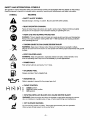
SAFETY
AND
INTERNATIONAL
SYMBOLS
This operator's manual describes safety and international symbols and pictographs that may appear on this product.
Read the operator's manual for complete safety, assembly, operating and maintenance and repair information.
SYMBOL
MEANING
,a,
• SAFETY
ALERT
SYMBOL
Indicates danger, warning, or caution. May be used with other symbols.
• READ OPERATOR'S
MANUAL
Failure to follow these instructions can result in serious injury. Read and follow all safety
precautions in the operator's manual before starting or operating this unit,
@
• WEAR
EYE AND HEARING
PROTECTION
WARNING: Thrown objects and loud noise can cause severe eye injury and hearing loss.
Always wear eye protection meeting ANSI Z87.1-1989 standards and hearing protection
when operating this unit.
• THROWN
OBJECTS
CAN CAUSE
SEVERE
INJURY
WARNING: Keep clear of blower outlet. Never point the blower at yourself or others.
Objects can be thrown from blower. Do not operate unit without proper attachments and guards
in place.
• KEEP CHILDREN
AWAY
WARNING: Keep all bystanders, especially children and pets, at least 50 feet (15 m)
from the operating area. Stop the unit immediately if you are approached.
5-7x
• PRIMER
BULB
Push primer bulb fully and slowly, 5 to 7 times.
• UNLEADED
FUEL
Always use clean, fresh unleaded fuel.
• INDICATES
OIL
Refer to operator's manual for the proper type of oil.
A
B
H I",1
C
• CHOKE
CONTROL
CHOKE
PARTIAL position.
choke position.
C
RUN position.
• ROTATING
IMPELLER
BLADES
CAN CAUSE SEVERE
INJURY
WARNING: Stop the engine and allow the impeller to stop before opening the vacuum
door or installing or changing tubes or bag, or before performing any maintenance.
• HOT SURFACE
WARNING
Do not touch the engine or muffler, These parts get extremely hot from operation,
When turned off they remain hot for a short time,
-5-
SYMBOL
I
MEANING
• ON/OFF STOP CONTROL
ON / START / RUN
o@
• ON/OFF
STOP CONTROL
OFF or STOP
• THRO'n'LE
CONTROL
Indicates "HIGH" or "FASTEST" speed.
• THROTTLE
CONTROL
Indicates "IDLE", "LOW" or "SLOWEST" speed.
A
This unit is vacuum capable and the vacuum attachment
comes with your unit.
Be sure to read and follow all safety, assembly and
operating instructions outlined in this operator's manual.
CARTON
CONTENTS
•
Blower
•
Blower Tube
•
Operator's Manual
•
Bottle of 2-Cycle Engine Oil
•
Upper VacuumTube
•
Lower Vacuum Tube
•
Vacuum Bag
ASSEMBLY
,_
•
WARNING: Do not use parts, accessories or
attachments not authorized by Craftsman® for
this unit. Doing so could lead to serious injury to
the user, or damage to the unit, and void your
warranty.
ASSEMBLING
UNIT AS A BLOWER
Blower Tube Assembly
stop
the engine
allowserious
the impeller
to stop
WARNING:
Toand
prevent
personal
injury,
before installing or changing tubes,
,_
or damage to To
WARNING:
theprevent
unit, theserious
blower personal
tube must
injury
be
installed while operating this unit as a blower.
INFORMATION
NOTE: If the unit was assembled as a vacuum unit,
remove all vacuum parts and store away in a secure
place for later use.
your
unit is properly
assembled.
Make
sure all
WARNING:
If received
assembled,
ensure
fasteners are in place and secure.
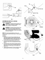
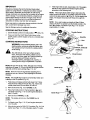
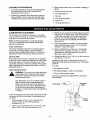
Installing
•
Install the blower tube over the blower outlet and
push on until both tabs snap into place (Fig. 1).
No tools are required for assembly
Removing
•
-6-
Remove the blower tube by pressing both tabs at the
same time and pulling off the blower (Fig. t).
Tab
Notch
Tabs
Upper Vac Tube
Fig. 2
Fig. 1
ASSEMBLING
UNIT AS A VACUUM
Vacuum Tube Assembly
stop
the engine
allowserious
the impeller
to stop
ARNING:
To and
prevent
personal
injury,
before installing or changing tubes.
_ll
A
Tab Button
WARNING: To prevent serious personal injury
or damage to the unit, always install vacuum
tubes, vacuum bag and make sure the vacuum
bag is completely zipped closed when operating
this unit as a vacuum.
Fig. 3
NOTE: If the unit was assembled as a blower unit,
remove all blower parts and store away in a secure place
for later use.
Installing
1, Assemble the vacuum tube by installing the lower
tube into the upper tube with the tab on the lower
tube aligning with the notch on the upper tube. Push
the lower tube down and snap into place (Fig, 2)
2,
Turn the unit over and open the vacuum door by
pressing the tab button and swinging the door open
(Fig. 3).
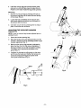
3.
Install the upper vacuum tube by hooking under the
hinge of the vacuum door and positioning the tube to
where the knob threads align with the tapped hole
(Figs 4 & 5).
4.
Tighten the knob securely. The tube should set even
with the bottom of the unit. Do not over tighten.
Fig. 4
Knob
Fig, 5
-7-
5.
Install the vacuum bag tube over the blower outlet
and push on until both tabs snap into place (Fig. 6).
Position so the elbow inside the bag slants upwards.
Removing
1. Remove the vacuum bag by pressing both tabs on
the vacuum bag elbow at the same time and pulling
off the blower (Fig. 6).
2.
Loosen the knob completely on the vacuum tube,
swing back slightly and unhook from the bottom of
the vacuum door to remove.
3.
Close the vacuum door by pressing down to snap in
place. Ensure the door is secure.
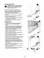
ADJUSTING THE SHOULDER
(vacuum kit)
HARNESS
NOTE: Have the vacuum bag harness adjusted prior to
starting the unit.
1. Extend the harness opening fully.
2.
Place the harness over your head and onto your left
shoulder. Hold the unit in the operating position to get
a proper adjustment (Fig. 7).
3.
Make sure the vacuum bag harness is adjusted to
allow free flow of air into the vacuum bag elbow. If
the bag is kinked, the unit will not perform correctly.
The bottom of the bag should be parallel to the
ground (Fig. 7).
4.
Lengthen the harness by pulling down on the strap
and moving the buckle up. Shorten the harness by
pulling the strap back through the buckle while
moving the buckle down (Fig. 8)
Flg. 7
\
Fig. 8
Tabs
Fig. 6
-8-
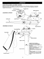
KNOWYOUR
BLOWER
or BLOWER/VACUUM
READ THIS OPERATOR'S MANUAL AND SAFETY RULES BEFORE OPERATING YOUR UNIT. Compare the
illustrations with your unit to familiarize yourself with the location of various controls and adjustments. Save this
manual for future reference.
Throttle Control
On/Off Stop Control
Primer Bulb
Assembled
as a Blower
Blower Tube
\
Assembled
Starter Rope Grip
Fuel Cap
Choke Control
Air Filter Cover
,%,
as a Vacuum
Vacuum Inlet Door
Cap
Vacuum Bag Elbow
Vacuum Bag
\
Knob
Vacuum Inlet Door
Upper Vac Tube
ON/OFF STOP CONTROL - a
momentary switch used to STOP
the engine. The switch is always in the
ON position.
THROTTLE CONTROL - controls engine
speed for various applications.
Lower Vac Tube
PRIMER BULB - removes air from the
fuel lines and fills the carburetor with
fuel.
CHOKE CONTROL - the choke helps
to supply fuel to the carburetor during
starting. This helps in starting a cold
engine.
Shoulder Harness
-9-
THIS ENGINE
IS CERTIFIED
TO OPERATE
ON UNLEADED
GAS AND OIL MIXTURE.
TO FUEL ENGINE
OII and Fuel Mixing Instructions
A
Thoroughly mix the proper ratio of unleaded gasoline with
2-cycle engine oil in a separate fuel can, 40:1. Do not mix
them directly in the engine fuel tank.
A
CAUTION: Be sure to read these instructions
carefully before attempting to start or operate
this unit. Using old or improper oil or fuel, or
improperly mixing the oil and fuel can cause
engine damage. This type of damage will VOID
the engine warranty.
Use 3.2 oz. (0.094 liter) of 2-cycle engine oil per one gallon of unleaded gasoline to achieve a 40:1 fuel/oil ratio.
Use of Blended Fuels
If you choose to use a blended fuel or its use is unavoidable, the following precautions are recommended.
WARNING: Gasoline is extremely flammable
and its vapors can explode if they are ignited.
Always stop the engine and allow it to cool
before filling the fuel tank. Do not smoke while
filling the tank. Keep sparks and open flames
away from the area.
Recommended
1. Always use fresh fuel mix.
Use a special additive.
3.
Always agitate the fuel mix before fueling the unit.
4.
Drain the tank and run the engine dry before storing
the unit.
Oil Type
Use of Fuel Stabilizer
A 3.2 oz. (0.094 liter) bottle of Craftsman engine oil,
containing fuel stabilizer, is included with your product.
Craftsman brand oil is recommended for this outdoor
power tool. If another brand is used, make sure it is high
quality oil, formulated for 2-cycle, air-cooled engines.
A
2.
If using a brand of oil other than Craftsman, use of fuel
stabilizer will inhibit corrosion and minimize the formation
of gum deposit. Add 0.8 oz. (23 ml) per gallon of fuel per
instructions on container. NEVER add fuel stabilizer
directly to the unit's fuel tank. Using a fuel stabilizer can
keep fuel fresh for up to six (6) months.
DANGER: Combustible mixture contains
petroleum distillate. Store away from heat or
open flame. Harmful or fatal if swallowed. If
swallowed, do not induce vomiting. CALL
PHYSICIAN IMMEDIATELY. Avoid prolonged
contact with skin. Wash thoroughly after
handling. Do not reuse bottle.
A
Recommended Fuel Type
Use clean, fresh, unleaded gasoline that is less than 60
days old.
-10-
CAUTION: For proper engine operation and
maximum reliability, pay strict attention to the oil
and fuel mixing instructions on the 2-cycle oil
container. Use a 40:1 fuel/oil ratio. Use 2-cycle
oil. Using improperly mixed fuel can severely
damage the engine.
IMPORTANT
7.
Experience indicatesthat alcohol blended fuels (called
gasohol or using ethanol or methanol) can attract moisture
which leads to separation and formation of acids during
storage. Acidic gas can damage the fuel system of an engine
while in storage. To avoid engine problems, empty the fuel
system before storage of 30 days or longer. Drain the fuel
tank, start the engine and let it run until the fuel lines and
carburetor are empty. Use fresh fuel next season.
NOTE: If the engine floods while tryingto start, place the
choke controlin the RUN (IH C) position.Move the throttle
control to the fast position ( 4_ ) (Fig 10). PuiI the starter rope
briskly. The engine shouldstart with three (3) to eight (8)
pulls.
NOTE: For a warm engine, go directly to Step 6. Move
choke to RUN (I} I C) position and the throttle controlin the
fast ( _ ) position. Pull starter rope (Figs. 11 & 12) until
engine starts(1-7 pulls).
Never use engine or carburetor cleaner products in the fuel
tank, or permanent damage may occur.
See the Storage section for additional information.
STOPPING
If the engine fails to start, repeat steps 1-6. If the engine
stillfails to start,perform the flooded engine starting
procedure in the following note.
INSTRUCTIONS
1,
Set the throttle control to the idle position ("JP) (Fig. 10).
2.
Press and hold the On/Off Stop Control down in the
STOP position untilthe engine comes to a complete stop
(Fig. 10).
Throttle Control
Control
S|owlldte
Fast
STARTING INSTRUCTIONS
WARNING: Avoid accidental starting.Be in the
starting position whenever pullingthe starter rope.
The operatorand unitmust be in a stable position
while starting.
Primer Bulb
RUN (C)
(e)
CHOKE (A)
/
Also, Do not set unit on any surface except a
clean, hard area while starting.Debris such as
gravel, sand, dust, grass, etc. could be picked up
by the air intake and thrown out by the
discharge opening, damaging unit, property, or
causing serious injury to bystanders or operator.
Choke Control
Fig.10
NOTE: Mix gas with oil (40:1 ratio). See gas and oil mixing
instructions on page 10. Fii{your unit with oil and gas mixture
and hold unit firmly when starting (Figs. 11 & 12).
Sterter Rope
NOTE: Have the vacuum bag hamess adjusted prior to
startingthe unit as a vacuum. See Adjusting the Shoulder
Hamess.
NOTE: The On/Off Stop Control is a momentary switch and
is always in the ON position (Fig. 10).
1.
Fully press and release primer bulb slowly5 to 7 times.
Fuel should be visible in the bulb (Fig. 10). If fuel is not
visible, press three (3) more times, or until it is.
2.
Move choke lever (Fig. 10) to CHOKE (H A).
3.
Place the throttle control in the fast position ( _ ) and
pull starter rope (Figs. 11 & 12) until engine attempts to
start (1-3 pulls).
4.
Fig. 11
Starter Rope
Move choke to PARTIAL (N B).
NOTE: The engine witlnet run in the CHOKE (H A)
position.
5.
Pull starter rope (Figs, 11 & 12) until engine attemptsto
run (1-3 pulls).
6.
Move choke control to RUN (1÷1C) position (Fig. 10). Pull
starter rope (Figs. 11 & 12) until engine starts (1-7 pulls).
Fig. 12
-11 -
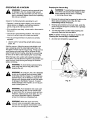
HOLDING
A
THE BLOWER
WARNING: To prevent serious personal injury
to yourself or others, or damage to the unit,
make sure all tubes and guards are in place
before operating your unit.
Check for the following before operating the unit:
• Operator is wearing proper clothing, such as boots,
safety glasses or goggles, ear/hearing protection,
gloves, long pants and long sleeve shirt.
• If the conditions are dusty, a dust mask or face mask is
being worn.
• The unit is in good working condition. The tubes and
guards are in place and secure.
1. Use the unit for cleaning debris away from driveways,
walls and fences (Figs 13 & 14).
2.
Fig,13
Use for cleaning around gardens, shrubbery and
trees (Fig. 15)
OPERATING
TIPS
• To reduce the risk of hearing lose associated with
sound level(s), the use of hearing protection is
required.
• Operate power equipment only at reasonable hours not early in the morning or late at night when people
might be disturbed. Comply with time listed in local
ordinance. Usual recommendations are 9:00 am to
5:00 pro, Monday through Saturday.
• To reduce noise levels, limit the number of pieces of
equipment used at any one time.
• To reduce noise levels, operate power blowers at the
lowest possible speed to do the job.
• Check your equipment before operation, especially the
muffler, air intakes, and air filters,
Fig. 14
• Use rakes and brooms to loosen debris before blowing.
• In dusty conditions, slightly dampen surfaces or use a
mister attachment when water is available.
• Conserve water by using power blowers instead of
hoses for many lawn and garden applications, including areas such as gutters, screens, patios, grills, porches, and gardens.
• Watch out for children, pets, open windows, or freshly
washed cars, and blow debris away.
• Use full blower nozzle extension so the air stream can
work close to the ground.
• After using blowers and other equipment, CLEAN UP!
Dispose of debris in trash receptacles.
Fig. 15
-12-
OPERATING
A
Emptying the Vacuum Bag
AS A VACUUM
WARNING: To avoid serious personal injury,
turn off the unit and allow the impeller to stop
before opening vacuum door or installing
or removing vacuum bag,
WARNING: TO prevent serious personal injury
or damage to the unit, always install vacuum
tubes, vacuum bag and make sure the vacuum
bag is completely zipped closed when operating
this unit as a vacuum.
1. Remove the vacuum bag by pressing the tabs on the
elbow tube and pulling it out of the unit, See
Assembling Unit as A Vacuum.
Check for the following before operating the unit:
• Operator is wearing proper clothing, such as boots,
safety glasses or goggles, ear/hearing protection,
gloves, long pants and long sleeve shirt.
2. Wearing eye protection and a dust mask, unzlp the
vacuum bag and empty the contents into a garbage
bag or container.
• If the conditions are dusty, a dust mask or face mask is
being worn.
3. Turn the bag inside out after initial emptying and
vigorously shake out dust and debris.
• The unit is in good working condition. The vacuum
tubes and vacuum bag are in place and secure.
NOTE: If addition cleaning of the bag is required, see
Cleaning the Vacuum Bag in Maintenance.
• The vacuum bag harness is in place and correctly
adiusted.
4.
Zip close and reinstall the vacuum bag.
1. Use the unit for vacuuming up light debris, leaves,
paper, etc.
Hold the vacuum, tilting the vacuum tube slightly, and
use a sweeping action to collect light debris (Fig. 16).
The debris will flow into the vacuum bag. Things such as
sma_l leaves and small twigs wilt be mulched as they
pass through the fan housing, allowing the vacuum bag
to hold a lot of debris. See Emptying the Vacuum Bag.
When the bag is full, suction will noticeably decrease.
Turn off the unit and allow the impeller to stop before you
unzip the bag. Unzip the bag and empty the contents
before continuing.
,_
A
A
A
never
unzip the
bag without
first injury,
WARNING:
To vacuum
avoid serious
personal
stopping the unit.
WARNING: As a vacuum, the unit is designed
to pick up dry material such as leaves, grass,
small twigs and bits of paper. To avoid serious
personal injury, do not attempt to vacuum wet
debris and/or standing water as this may result
in damage to the Blower/Vacuum. To avoid
severe damage to the impeller, do not vacuum
metal, broken glass, etc.
Fig. 16
WARNING: Avoid situations that could catch
the vacuum bag on fire. Do not operate near
an open flame. Do not vacuum warm ash from
fireplaces, barbecue pits, brush piles, etc. Do
not vacuum discarded cigars or cigarettes
unless the cinders are completely cool.
WARNING: When the upper and lower
vacuum tubes are removed, make sure the
vacuum door is snapped closed before using
the unit, to avoid injury from the impeller.
-13-
MAINTENANCE
SCHEDULE
FREQUENCY
MAINTENANCE
REQUIRED
Before each use
Check for loose or damaged parts.
Before each use
Check for loose fasteners and parts.
Between each use
Clean units and labels.
Every 10 hours
Clean and re-oil air filter
Every 50 hours
Check spark plug condition and gap.
GENERAL
RECOMMENDATIONS
AIR FILTER MAINTENANCE
NOTE: Clean and re-oil the air filter every 10 hours of
operation. Your unit's air filter is one of the most
important areas to maintain. If it is not maintained, you
will VOID the warranty. Before cleaning, make sure the
unit is turned off.
WARNING: To prevent serious injury, never
perform maintenance on the unit while it is
running. Shut off the unit and allow it to cool
down before doing any maintenance.
Disconnect the spark plug wire to prevent the
unit from starting.
1. Wipe down the air filter cover and surrounding area.
This will help prevent any debris entering the
carburetor when the cover is removed.
The warranty on this blower does not cover
items that have been subjected to operator abuse or
negligence. To receive full value from the warranty, the
operator must maintain the unit as instructed in this
operator's manual.
2.
3. Remove the air filter (Fig. 18).
These required maintenance procedures should be
performed at the frequency stated in the table. They
should also be included as part of any seasonal tune-up.
CHECK
FOR
DAMAGED/WORN
4.
FOR LOOSE FASTENER
Wash the filter in detergent and water (Fig. 19). Rinse
the filter thoroughly and allow it to dry.
5. Apply enough clean oil to saturate and squeeze out
excess (Fig. 20).
PARTS
6. Squeeze the filter to spread the oil (Fig. 21).
Inspect the unit for any worn or damaged parts. Repair or
replace damaged parts before operating.
CHECK
Remove the screws on each side of the air filter
cover. Remove the air filter cover (Fig. 17).
7.
PARTS
Reinstall the filter (Fig. 18), air filter cover and screws
(Fig. 17).
NOTE: If the unit is operated without the air filter cover
installed you will VOID the warranty.
• Housing Screws
• Air Filter Cover
• Spark Plug Wire
CLEAN
UNIT
AND
LABELS
• Clean the unit and labels using a damp cloth with a
mild detergent.
• Wipe off the unit with a clean dry cloth.
• Keep air vents free from debris at all times.
Air Filter Cover
Screws
Fig. 17
-14-
TO REPLACE
Use a Champion DJ7Y spark plug (or equivalent).
Correct air gap is 0.020 in. (0.50 mm). Remove plug
after every 50 hours of operation and check its condition
(Fig. 22).
m
1. Stop the engine and remove the air filter cover. See
Air Filter Maintenance.
o
Air Filter
SPARK PLUG
2.
Pull the wire off of the spark plug.
3.
Clean around the spark plug and remove it from the
cylinder head.
®
NOTE: Replace a cracked, fouled or dirty spark plug. Do
not sand blast, scrape or clean electrodes because the
engine could be damaged by grit entering the cylinder.
Fig. 18
<
.
Set the air gap at 0.020 in. (0.50 mm) using a wire
feeler gauge (Fig. 22). Install a correctly gapped
spark plug into the cylinder head. Torque to
110-120 inolb (12.3-13.5 N°m).
0.020 in.
(0,50 mm)
Fig. 19
Fig. 22
CLEARING
A
Fig. 20
1,
Fig. 21
-15-
A BLOCKED
IMPELLER
WARNING: During normal operation, parts of
this unit become hot. Wear protective clothing
and observe all safety instructions to prevent
serious personal injury.
Shut off the unit and wait for the engine to come to a
complete stop. Disconnect the spark plug wire to
prevent the unit from starting.
2.
Remove the vacuum tubes. See Assembling Unit
as a Vacuum. The vacuum bag can also be removed
for easier handling of the unit.
3.
Carefully remove material blocking the impeller.
Inspect the blades to assure no damage has
occurred. Rotate the blades by hand to assure the
blockage is completely cleared.
4,
Reconnect the spark plug wire.
5.
Replace the vacuum bag and vacuum tubes.
6.
Restart unit and resume use.
CLEANING
THE VACUUM
BAG
3. Wash the bag once a year or more often if needed as
follows:
1. Empty the bag after each use to avoid deterioration
and obstructing air flow, which will reduce the
performance of the vacuum.
2.
a. Remove the vacuum bag.
b. Turn bag inside out.
Wearing eye protection and a dust mask, clean the
bag as needed. Turn the bag inside out after initial
emptying and vigorously shake out dust and debris.
c. Hang up.
d. Hose down thoroughly.
e. Hang to dry.
f. Turn bag right side out.
CARBURETOR
ADJUSTMENT
.
The idle speed of the engine is adjustable, the air filter
cover must be removed to do so. Only make adjustments
while the unit is assembled as a blower.
NOTE: Careless adjustments can seriously damage
your unit. An authorized service dealer should make
carburetor adjustments.
Restart the unit, release the throttle trigger and let the
engine idle. If the engine stops, insert a small phillips
or flat blade screwdriver into the idle speed screw
(Fig. 23). Turn the idle speed screw in, clockwise,
1/8 of a turn at a time (as needed) until the engine
idles smoothly.
If the engine seems to idle fast, turn the idle speed
screw counterclockwise 1/8 of a turn at a time (as
needed), to reduce idle speed.
4.
Check Fuel Mixture
Old and/or improperly mixed fuel is usually the reason
for the unit not running properly. Drain and refill the
tank with fresh, properly mixed fuel prior to making any
adjustments. Refer to Oil and Fuel Information Pg. 10.
5.
Clean Air Filter
6.
The condition of the air filter is important to the operation
of the unit. A dirty air filter will restrict air flow and change
the air/fuel mixture. This is often mistaken for an out of
adjustment carburetor. Check the condition of the air filter
before adjusting the idle speed screw. Refer to Air Filter
Maintenance Pg. 14.
Checking the fuel mixture, cleaning the air filter, and
adjusting the idle speed screw should solve most engine
problems.
If not and:
Before reinstalling the air filter cover, Turn the idle
speed screw in, clockwise, 1/8 of a turn. This will
compensate for the speed reduction when the air
filter cover is back in place.
Reinstall the filter (Fig. 18, Pg. 15), air filter cover and
screws (Fig. 17, pg. 14).
• The engine will not idle,
Adjust Idle Speed Screw
A
• The engine hesitates or stalls on acceleration,
WARNING: The unit will be running during idle
speed adjustments. Wear protective clothing
and observe all safety instructions to prevent
serious personal injury.
• There is a loss of engine power,
have the unit checked and adjusted by an authorized
service dealer.
Also, Do not set unit on any surface except &
clean, hard area during these adjustments.
Debris such as gravel, sand, dust, grass, etc.
could be picked up by the air intake and thrown
out by the discharge opening, damaging unit,
property, or causing serious injury to bystanders
or operator.
Primer Bulb
Idle Speed
Screw
If after checking the fuel mixture and cleaning the air filter
the engine still will not idle, adjust the idle speed screw
as follows.
hoke
Control
1. Start the engine and let it run at a high idle for a
minute te warm up. See Starting/Stopping
Instructions, Pg. 15.
2. Shut the unit off and remove the air filter cover. See
steps 1 and 2 of Air Filter Maintenance Pg. 14.
Fig. 23
-16-
Fuel stabilizer is an acceptable alternative in
minimizing the formation of fuel gum deposits during
storage. Add stabilizer to the gasoline in fuel storage
container. Follow the mix instructions found on
stabilizer container. Run engine at least five
(5) minutes after adding stabilizer.
It is important to prevent gum deposits from forming in
essential fuel system parts such as the carburetor, fuel
filter, fuel hose or tank during storage. Also, experience
indicates that alcohol blended fuels (called gasohol or
using ethanol or methanol) can attract moisture which
leads to separation and formation of acids during
storage. Acidic gas can damage the fuel system of an
engine during storage.
CRAFTSMAN 40:1,2-cycle engine oil is already
blended with fuel stabilizer. If you do not use this
Craftsman oil, you can add a fuel stabilizer to your
fuel. NEVER add fuel stabilizer directly to the unit's
fuel tank.
To avoid engine problems, the fuel system should
be emptied before storage of 30 days or longer.
Follow these instructions:
1. Drain all fuel from the fuel tank and drain into a
container with the same 2-cycle fuel mixture. Do not
use fuel that has been stored for more than 60 days.
Dispose of the old fuel/oil mix in a safe manner and
use a fresh mix.
2.
Start the engine and allow it to run until it stalls.
This ensures that all fuel has been drained from
the carburetor.
3.
Under To Fuel Engine in the Operation section of this
manual, refer to the message labeled IMPORTANT,
regarding the use of gasohol in your engine.
4.
Allow the engine to cool. Remove the spark plug and
put about 1 oz. (30 ml) of any high quality motor oil or
2-cycle oil into the cylinder. Pull the starter rope
slowly to distribute the oil. Reinstall the spark plug.
NOTE: Remove the spark plug and drain all of the oil
from the cylinder before attempting to start the unit after
storage.
5.
Thoroughly clean the unit and inspect for any loose
or damaged parts. Repair or replace damaged parts
and tighten loose screws, nuts or bolts. The unit is
now ready for storage.
6. Store the unit in a dry, well ventilated area and out of
the reach of children.
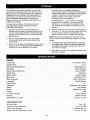
ENGINE
Engine Type ...................................................................
Displacement ............................................................................
Air-Cooled,
Operating RPM (Maximum)
.......................................................
Idle Speed .....................................................................
Blower Output (Maximum)
...........................................................
Ignition Type ..........................................................................
Ignition Switch .....................................................................
rpm
rpm
up to 210 MPH
Champion DJ7Y
0.020 in. (0.50 mm)
Fuel/Oil Mixture
40:1
Carburetor .................................................................
Starter ............................................................................
Diaphragm, All-Position
Auto Rewind
Muffler ........................................................................
Baffled with Guard
Throttle ..................................................................................
Lever
................................................................
18 oz. (530 ml)
Bearings ........................................................................
Weight (Blower, no fuel) ..........................................................
VACUUM
8,000-8,600
3,400-4,000
Electronic
Rocker Switch
Spark Plug ......................................................................
Spark Plug Gap ...............................................................
Lubrication .......................................................................
Fuel/Oil Ratio .............................................................................
Fuel Tank Capacity
2-Cycle
31 cc
Needle and Ball
10.8 Lbs. (4.9 kg)
OPTION
Mulching Ratio ........................................................................
Up to 16:1
Vacuum Air Flow (Maximum)
.........................................................
Vacuum Bag Capacity ..........................................................
Weight (Vacuum Bag Empty, no fuel) ................................................
-17-
up to 510 CFM
2.1 Bushels (40.7 L)
12.5 Lbs. (5.7 kg)
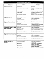
CAUSE
TROUBLE
Engine will not start
Engine will not idle
Engine will not accelerate
Engine lacks power or stalls
when under load
Engine smokes
excessively
Unit will not blow or
vacuum
REMEDY
Empty fuel tank
Fill fuel tank
Primer bulb wasn't pushed enough
Press primer bulb fully and slowly
5-7 times, Fuel should be visible in
the bulb
Fouled spark plug
Clean or replace spark plug; re-gap.
Engine flooded
Use starting procedure WITHOUT
USING CHOKE
Old or improperly mixed fuel
Drain fuel tank/add fresh fuel mixture
Old or improperly mixed fuel
Drain fuel tank/add fresh fuel mixture
Dirty air filter
Clean or replace air filter
Carburetor misadjusted
Adjust carburetor
Old or improperly mixed fuel
Drain fuel tank/add fresh fuel mixture
Dirty air filter
Clean or replace air filter
Improper carburetor adjustment
Take to an authorized service dealer
for carburetor adjustment
Dirty air filter
Clean or replace air filter
No oil in fuel or old fuel
Drain fuel tank/add fresh fuel mixture
Fouled spark plug
Clean or replace spark plug; re-gap.
Improper carburetor adjustment
Take to an authorized service dealer
for carburetor adjustment
Choke partially on
Adjust choke.
Dirty air filter
Clean or replace air filter
Too much oil in fuel mixture
Drain fuel tank/add fresh fuel mixture
Improper carburetor adjustment
Take to an authorized service dealer
for carburetor adjustment
Vacuum bag full of debris
Empty bag. See Empty the
Vacuum Bag.
Blocked tube
Clear blockage. See Clearing a
Blocked Tube/Impeller
Blocked impeller
Clear blockage. See Clearing a
Blocked Tube/Impeller
Damaged impeller
Take to an authorized service dealer
-18-
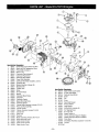
1
182441
2
182439
3
182524
4
5
182442
182443
6
180221
7
182444
8
181866
9
182445
10
181064
11
12
182446
182447
13
182525
14
15
182449
182450
16
182451
17
182452
18
182526
19
182454
20
182455
21
22
182456
182457
23
182458
24
25
182459
182460
26
182461
27
610311
28
29
182462
182463
30
182464
31
182493
32
182523
33
182494
@
On/Of Stop Control Switch with Wire
Switch and Coil Replacement Wires
Primer Bulb (includes 4)
Return Lines
Crankcase Plug (includes 6)
Crankcase Plug Screws
Crankcase Plug Gasket
Power Shaft Assembly
Crankcase Assembly (includes 6, 8 & 10)
Tinnerman Nut
Module Assembly (includes 12)
Module Screw
Throttle Lever
Screw
Air Cleaner Base
Washer
Carburetor Mount Screw
Carburetor
Carburetor Gasket
Spacer Mounting Screw
Carburetor Spacer
Cylinder Baffle Assembly (includes 41 & 42)
Piston and Rod Assembly
Cylinder Gasket
Cylinder Assembly (includes 24 & 26)
Cylinder Bolt
Spark Plug
Flywheel
Muffler Assembly (includes 30-34 & 37)
Muffler Mounting Screw
Spark Arrestor Screen
Spark Arrestor Gasket
Spark Arrestor Cover
Item
34
35
36
Part No.
182519
182515
182516
Descril#tion
Spark Arrestor Cover Screw
Air Filter Heat Shield
Carburetor Heat Shield
37
182188
Screw
38
39
182491
181930
Clip
Screw
40
41
182518
182564
Heat Shield Gasket
Exhaust Gasket
42
182563
Intake Gasket
43
182565
Muffler Baffle (includes 44)
44
182566
Setf Tapping Screw
182567
Kit, Foam Seal
182499
Engine Gasket Kit
182520
182521
O.E.M. Carburetor Repair Kit (Walbrc)
Gasket Diaphragm Repair Kit (Walbro)
180530
Piston Ring
182498
Short Block Assembly (includes 8-10 & 23-27)
610309
Oil Seal
Not Shown
-19-
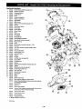
1
2
3
4
5
182465
182466
182467
182468
182469
HandleGrip Assembly(includes 2-5)
Vibration Dampener
Dampener Spacer
HandleScrew
Screw
6
7
8
9
10
11
12
13
14
15
16
17
18
19
20
21
22
23
24
25
26
27
28
29
30
31
32
33
34
35
36
182527
182471
182473
182474
182528
182482
182483
182484
182485
182486
613103
611061
181079
613102
182488
182487
182489
147049
182499
182529
182530
182495
182496
182497
181930
182568
182500
182531
182502
181064
182504
Diverter(includes9)
EngineCover Screw
Upper Baffle
Baffle Screw
EngineCoverAssembly(includes7-9)
Washer
Gear ReturnSpring
PulleyGear
FrictionSpring
StarterPulley
Rope
RopeGuide
PullHandle
RewindSpring
PulleyRetainerAssembly
Rope Guide RetainerAssembly
RecoilHousing
Screw
RecoilStarterAssembly(includes11-23)
FueICap
FuelTank Assembly(includes 25-28 & 30-31)
Fuel Line
Fuel LineAssembly
AssistHandle Cover
FuelTank Screw
Washer
Air Filter
Air FilterCover(includes23)
Ground Wire
Tinnerman Nut
Washer
37
38
39
40
41
42
43
44
45
182503
182506
182507
182508
182509
182510
182512
182513
182449
182478
182511
182532
Upper Housing Assembly (includes 35 & 36)
Impeller
Washer and Lock Nut Assembly
Lower Housing with Insert
FueI Tank Pad
Vacuum Door Assembly
Hinge Shaft
Spring
Screw
Blower Outlet Tube
Ring Reducer Gasket (on vacuum door)
Vacuum Bag Assembly (includes vacuum bag, cable tie
and vacuum bag adapter)
Vacuum Bag
Cable Tie
182533
612930
182477
182480
182479
182517
Vacuum Bag Adapter
Vacuum Tube Assembly (includes Upper Vacuum Tube,
Lower Vacuum Tube & Knob Assembly)
Upper Vacuum Tube
Lower Vacuum Tube
182481 Knob Assembly
182522 Operator's Manual
71-36549 Craftsman 2-Cycle Oil
Not Shown
- 20 -
- 21-
For in-home major brand repair service:
Call 24 hours a day, 7 days a week
1-800-4-MY-HOME
Para pedir servicio de reparacion
s" (1-800-469-4663)
a domicilio
- 1-800-676-5811
In Canada for all your service and parts needs call
Au Canada pour tout le service ou les pi_ces - 1-800-665-4455
For the repair or replacement parts you need:
Call 7 am - 7 pm, 7 days a week
1-800-366-PART
(1-800-366-7278)
Para ordenar piezas con entrega a domicilio - 1-800-659-7084
For the location of a Sears Parts and Repair Center in your area:
Call 24 hours a day, 7 days a week
1-800-488-1222
For information on purchasing a Sears Maintenance Agreement
or to inquire about an existing Agreement:
Call 9 am - 5 pm, Monday - Saturday
1-800-827-6655
HomeCentral
s"
'
SM
TheService
SideofSears