1
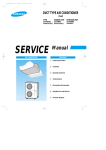
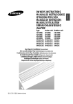
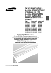
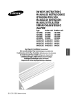
2-00216A(1)-PR
5/19/01 10:04 AM
Page 2-1
2. Installation
2-1 Wiring diagram
CN20 Connector
DIP Switch
MAIN PCB
SUB PCB
SW2
CN7
Rotary
Digital
Switch
SW1
Jumper
Wire
CN9
Receiver &
Display Unit
(Optional)
Indoor Unit
Transmitter
(Optional)
Ventilator
Motor
Float Switch
MAIN POWER
Wired
Remote
Controller
(Optional)
Centralized
Controller
(Optional)
Power
Earth
Drain Pump
Communication
220-240V~,
50Hz
Float Switch
Drain Pump
(Optional)
Outdoor Unit
MAIN POWER
3ø, 380-415V~,
50Hz
Cable Specifications
The following electrical characteristics must be respected.
MODEL
Power
Sub switch
Fuse
Min. size of electric Wires
from/to the indoor/outdoor unit
Size of electric
input wires
Samsung Electronics
20m or less
50m or less
ADH4400G / DH44ZA1(A2)
3Ø, 380-415V~, 50Hz
30A
30A
H07RN-F, 4G, 1.25mm2
H07RN-F, 3G, 2.5mm2
H07RN-F, 3G, 4.0mm2
Note
◆ The power cables are not
supplied with the air conditioner.
The user should purchase them separately.
◆ When connecting the cables to the
main power, you should connect each
cable(L1, L2 & L3) properly.
2-1
2-00216A(1)-PR
5/19/01 10:04 AM
Page 2-2
2-2 Wired Remote Controller Installation
Accessories
Wired Remote
Controller(1)
Cable-Tie(2)
Cable Clamp(5)
M4 X 16 Tapped
Screw(7)
Caution :
• Do Not keep the wired remote controller cables with a
220V cable because the remote controller cables have
low voltage.
• Do Not input 220V power to the R1, R2 and R3 in the
wired remote controller.
1. Disassemble the wired remote controller by
using two grooves on the top of it.
Note : Cable Specifications
Cable type
Size of cables
Max. length of electric wires from
the indoor unit to the wired remote
controller
Double-insulation, 3G
0.3mm2~0.75mm2
100m
4. Reassemble the wired remote controller.
2. Secure the rear cover of the wired remote
controller on the wall with two screws.
3. Connect the R1, R2 and R3 terminals in the
wired remote controller to the R1, R2 and R3
terminals on the electrical component box each.
Caution :
• The optional kits must be installed by an installation
specialist.
• Before installing the optional kits, ensure that you have
turned off the main power.
• All optional kits cables should be installed according to
the national wiring rules and you must install them in the
wall not to be touched by users.
Wired
Remote
Controller
2-2
Samsung Electronics
2-00216A(1)-PR
5/19/01 10:05 AM
Page 2-3
2-3 Wireless Remote Controller Installation
4. Close the receiver & display unit.
Accessories
Wireless Remote
Controller(1)
Battery(2)
M4 X 16 Tapped
Screw(2)
Remote Controller
Holder(1)
5. Secure the receiver & display unit on the wall
with two screws.
6. Reassemble the receiver & display unit cover.
Receiver &
Display Unit(1)
Cable-Tie(2)
Cable Clamp(5)
M4 X 16 Tapped
Screw(7)
Caution :
•The optional kits must be installed by an installation specialist.
•Before installing the optional kits, ensure that you have turned
off the main power.
Wire Kit
•All optional kits cables should be installed according to the
national wiring rules and you must install them in the wall not
to be touched by users.
Length : 10m
1. Remove the receiver & display unit cover by
using the tab on the bottom of it.
2. Open the receiver & display unit.
3. Connect the end of the connector wire to the
receiver & display unit and connect the other
end of the wire to the electrical component box
as shown in figure.
Caution :
•Do NOT keep the receiver & display unit cables with a
220V cable because the remote controller cables have
low voltage.
Samsung Electronics
2-3
2-00216A(1)-PR
5/19/01 10:05 AM
Page 2-4
2-4 Centralized Controller Installation
Accessories
Centralized
Controller(1)
Cable-Tie(2)
Cable Clamp(5)
M4 X 16 Tapped
Screw(7)
5. Connect the O1 and O2 terminals of the
centralized controller to the O1 and O2
terminals on the electrical component box as
shown in figure.
Note : Cable Specifications
Transmitter(1)
Spacer Support(4)
Cable-Tie(2)
M4 X 16 Tapped
Screw(7)
Cable type
Double-insulation,
2G(Shield Cable)
Size of cables
0.75mm2~1.25mm2
Max. length of electric wires from the
indoor unit to the centralized controller
1km
1. Open the centralized controller
cover by using two grooves on
the top of it.
2. Secure the rear cover of the centralized
controller on the wall with two screws.
3. Secure the transmitter
with four spacer supports
into the electrical
component box.
Centralized
Controller
6. Connect the power cables.
Note : Cable Specifications
Electrical component box
Transmitter
4. Connect the cable from the PCB and to the
transmitter.
And connect another cable from the O1, O2
terminals and to the transmitter as shown in
figure.
Cable type
Double-insulation, 2G
Size of cables
0.75mm2~1.25mm2
7. Reassemble the centralized controller.
Caution :
•The optional kits must be installed by an installation
specialist.
•Before installing the optional kits, ensure that you have
turned off the main power.
•All optional kits cables should be installed according to
the national wiring rules and you must install them in the
wall not to be touched by users.
2-4
Samsung Electronics
2-00216A(1)-PR
5/19/01 10:05 AM
Page 2-5
2-5 Air Filter Installation
1. Remove the air inlet duct flange.
3. To clean the air filter, remove the fixing bracket
on the base of air filter kit, then pull out the
filter.
2. Attach the air filter kit to the air inlet side of
indoor unit.
Note: Setting Up Filter Cleaning Cycle
• Adjust the DIP switch(SW2) in the main PCB to
the desired position referring the table below.
Switch No.
Switch Position
Filter Cleaning Cycle
4
ON
OFF
1,000 hours
2,000 hours
Caution :
•The optional kits must be installed by an installation
specialist.
•Before installing the optional kits, ensure that you have
turned off the main power.
•The optional air filter has to be cleaned only by an
authorized person or service agent.
Samsung Electronics
2-5
2-00216A(1)-PR
5/19/01 10:05 AM
Page 2-6
2-6 Drain Pump Installation
Care must be taken when installing the drain hose for
the indoor unit to ensure that any condensate water is
correctly drained outside.
4. Connect the cable to the electrical component
box as shown in figure.
1. Open the side of indoor unit.
Drain pump
Float
switch
5. Adjust the DIP switch(SW2) on the main PCB
according to the table below.
2. Screw the drain pump with two screws.
Note : When installing the drain pump, leave a 7mm
space between the bottom of the drain pan and
the drain pump.
Drain pump
Switch No.
Switch Position
2
3
ON
ON
Note : Wrap the drain tube outlet with an insulating
materials.
3. Connect the drain hose to the drain socket.
Drain pump hose
2-6
Samsung Electronics
2-00216A(1)-PR
5/19/01 10:05 AM
Page 2-7
2-7 Group Control Installation
* You should adjust the option switches in the electrical component box or on the PCB of the wired remote controller.
* Before setting up the option switches, always make sure that you have turned off the main power.
* After adjusting the options, you should supply the power. Otherwise, the options will not be applied.
2-7-1. With Wired Remote Controller
A user can operate up to sixteen air conditioners by using the wired remote controller In this case, the air conditioner can
be controlled by only one wired remote controller connected to the indoor unit and cannot be controlled by the others.
1. Connect the R1, R2 and R3 terminals in the wired remote
controller to the R1, R2 and R3 terminals in any indoor unit
“A” each.
2. Connect the R1 and R3 terminals in the indoor unit “A” to the
R1 and R3 terminals in another indoor unit “B”.
Unit A
CN20
Connector
Unit B
Caution :
When connecting the cables, you must keep these :
• The R1 terminals must be connected to the R1s.
• The R3 terminals must be connected to the R3s.
• Do not connect the R2 terminals to anywhere.
• If you connect R2 terminals, the PCB will be damaged.
Unit C
3. Connect the R1 and R3 terminals of “B” to any indoor unit
“C” and connect the others as the same way.
4. Remove the CN20 connectors on the sub PCBs except the unit
connected with remote controller(Adress “0”).
Switch No.
Number of
indoor unit(s)
Switch No.
Number of
indoor unit(s)
0
One
8
Nine
1
Two
9
Ten
2
Three
A
Eleven
3
Four
B
Twelve
4
Five
C
Thirteen
5
Six
D
Fourteen
6
Seven
E
Fifteen
7
Eight
F
Sixteen
5. Remove the CN20 connectors on the sub PCBs except the unit
connected with remote controller(Address “0”).
6. Adjust the DIP switch No. 2 in the wired remote controller to
“ON” position.
Note : You cannot install the centralized controller when the wired
remote controller for a group has already been installed.
Samsung Electronics
2-7
2-00216A(1)-PR
5/19/01 10:05 AM
Page 2-8
Product Specifications
2-7-2. With Centralized Controller
A user can turn on/off up to sixteen air conditioners by using the centralized controller.
In this case, the user can turn on/off all air conditioners or a specific air conditioner connected with the centralized
controller. And each air conditioner can be controlled by its own remote controller(s) depending on the setting.
1. Connect the O1 and O2 terminals in the centralized controller to
the O1 and O2 terminals in the indoor unit “A”.
2. Connect the O1 and O2 terminals in the indoor unit “A” to the
O1 and O2 terminals in another indoor unit “B”.
3. Connect the O1 and O2 terminals of “B” to any indoor unit “C”
and connect the others as the same way.
4. Adjust the DIP switch(DS01) in the centralized controller to the
desired position referring to the table below.
Switch
No.
1
2
3
4
Meaning
The air conditioner is operated by the controller
Centralized
Controller
OFF OFF OFF OFF adjusted last among the wired remote controller,
wireless remote controller and centralized controller.
Switch
OFF OFF OFF ON
Position
OFF OFF ON
A user can use wired/wireless remote controller when
the centralized controller is switched on.
And he/she cannot use the remote controller(s) when
the centralized controller is switched off.
Unit A
Unit B
Unit C
The air conditioner(s) can be controlled by only the
OFF centralized controller. The user cannot use the
wired/wireless remote controller in this case.
5. Adjust the rotary switch on the transmitter to the desired position
referring to the table on page 2-11.
Centralized
Controller
Note : You cannot install the centralized controller when the wired remote
controller for a group has already been installed.
2-8
Samsung Electronics
2-00216A(1)-PR
5/19/01 10:05 AM
Page 2-9
2-8 Setting Up Option Switches
IMPORTANT : Before setting up the option switches, always make sure that you have turned off the main power.
Main PCB in the Indoor Unit
Rotary Switch(SW1)
A user can operate up to sixteen air conditioners by using the wired remote
controller. Before controlling more than one air conditioner, you should
connect the air conditioner each other. And you must assign addresses to the
air conditioners. For further details on connecting air conditioners.
If the user would like to controller only one air conditioner, make sure that
the arrow is at “0” position.
Turn the arrow to the desired position referring to the table below.
Switch No.
Number of
indoor unit(s)
Switch No.
Number of
indoor unit(s)
0
One
8
Nine
1
Two
9
Ten
2
Three
A
Eleven
3
Four
B
Twelve
4
Five
C
Thirteen
5
Six
D
Fourteen
6
Seven
E
Fifteen
7
Eight
F
Sixteen
DIP Switch(SW2)
Adjust the switch to the desired position referring to the table below.
Switch
No.
Option Item
Switch Position
ON
OFF
Note
1
Ventilator Fan
Not installed
Installed
Not supplied
2
Drain Pump
Installed
Not installed
3
Float Switch
Installed
Not installed
Optionally
supplied
4
Filter Cleaning Cycle
1,000 hours
2,000 hours
5
Indoor Fan Motor Speed Normal
High speed
Caution :
• If you do not adjust the switch when not installing the drain pump, "✳9" error
will occurs. If this happens, adjust the No.2 and No.3 switches to the "OFF"
position.
Samsung Electronics
2-9
2-00216A(1)-PR
5/19/01 10:05 AM
Page 2-10
Setting Up Option Switches (Cont.)
Sub PCB in the Indoor Unit
CN20 Connector
Remove the CN20 connector in the sub PCB, if necessary, referring to the
table below. (This procedure is needed only when the user would like to
control a group by using the wired remote controller.)
Address
Situation of the CN20 Connector
0
Connected
1-F
Removed
Unit A
(Address 0)
CN20 Connector
Unit B
(Address 1)
Unit C
(Address 2)
Note : ◆ Up to 16 air conditioners can be controlled with one wired remote
controller.
Note : ◆ If the user does not want to control a group, do not remove the
CN20 Connector.
PCB in the wired remote controller
Dip Switch(DS01)
Adjust the DIP switch to the desired position referring to the table below.
Switch
No.
2-10
Option Item
1
Type of unit
2
Number of air conditioner(s) controlled
by the wired remote controller
3
Basic specification
4
Using wireless remote controller
Switch Position
ON
OFF
Cooling only
Heat pump
Group
controlling
One indoor unit
controlling
-
O
Can be used
Cannot be used
Samsung Electronics
2-00216A(1)-PR
5/19/01 10:05 AM
Page 2-11
Installation
Centralized Controller
DIP Switch(DS01)
Adjust the DIP switch to the desired position referring to the table below.
Switch
No.
1
2
3
4
Meaning
The air conditioner is operated by the controller
OFF OFF OFF OFF adjusted last among the wired remote controller,
wireless remote controller and centralized controller.
Switch
OFF OFF OFF ON
Position
A user can use wired/wireless remote controller when
the centralized controller is switched on.
And he/she cannot use the remote controller(s) when
the centralized controller is switched off.
The air conditioner(s) can be controlled by only the
OFF OFF ON OFF centralized controller. The user cannot use the
wired/wireless remote controller in this case.
Note : You cannot install the centralized controller
when the wired remote controller for a group
has already been installed.
Transmitter
Rotary Switch(DS01)
A user can turn on/off up to sixteen air conditioners by using the centralized controller. To use the controller,
you must assign addresses to the air conditioners. For further details on connecting air conditioners.
If the user would like to controller only one air conditioner, make sure that the arrow is at “0” position.
Turn the arrow to the desired position referring to the table below.
Switch No.
Number of
indoor unit(s)
Switch No.
Number of
indoor unit(s)
0
One
8
Nine
1
Two
9
Ten
2
Three
A
Eleven
3
Four
B
Twelve
4
Five
C
Thirteen
5
Six
D
Fourteen
6
Seven
E
Fifteen
7
Eight
F
Sixteen
Original Position of Option Switches
The option switches are preset by the manufacturer. Refer to the table below, if necessary.
Option Place
Main PCB in the
indoor unit
Component No.
State
Rotary Switch(SW1)
0
DIP Switch(SW2)
ON
Jumper Wire(SW05)
SHORT
Sub PCB in the indoor unit
CN20 Connector
Connected
Wired Remote Controller
DIP Switch(DS01)
OFF
Centralized Controller
DIP Switch(DS01)
OFF
Transmitter
Rotary Switch(DS01)
0
Samsung Electronics
Note : Before setting up the options, always make sure that you
have switched off the main power.
Note : After adjusting the options, you should supply the power.
Otherwise, the options will not be applied.
2-11
2-00216A(1)-PR
5/19/01 10:05 AM
Page 2-12
MEMO
2-12
Samsung Electronics