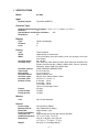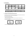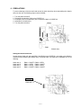
1
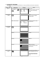
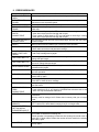
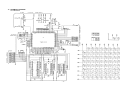
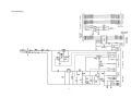
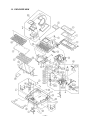
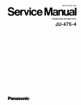
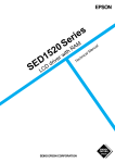
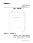
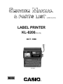
(without price)
LABEL PRINTER
KL-8200(ZX-579)
OCT. 1996
KL-8200
R
CONTENTS
1. SPECIFICATIONS --------------------------------------------------------------------------------- 1
2. MEASUREMENT ----------------------------------------------------------------------------------- 2
3. CLEANING THE PRINTER HEAD AND ROLLER ---------------------------------------- 2
4. RESET OPERATION ----------------------------------------------------------------------------- 3
5. BLOCK DIAGRAM -------------------------------------------------------------------------------- 4
6. PRECAUTIONS ------------------------------------------------------------------------------------ 5
7. LSI PIN FUNCTION ------------------------------------------------------------------------------- 6
8. DIAGNOSTIC PROGRAM ----------------------------------------------------------------------- 7
9. ERROR MESSAGES ----------------------------------------------------------------------------- 9
10. SCHEMATIC DIAGRAMS --------------------------------------------------------------------- 10
10-1. Main Block ------------------------------------------------------------------------------------------- 10
10-2. Power Supply --------------------------------------------------------------------------------------- 11
10-3. LCD Block-------------------------------------------------------------------------------------------- 12
10-4. Sub Block -------------------------------------------------------------------------------------------- 13
11. PARTS LIST --------------------------------------------------------------------------------------- 14
12. EXPLODED VIEW ------------------------------------------------------------------------------- 16
1. SPECIFICATIONS
Model:
KL-8200
Input
Keyboard layout:
Typewriter (QWERTY)
Character Types
.
Alpha (English and other languages): 52 (A ~ Z, a ~ z), 99 (Á, ß, Ç, Z etc.)
Numbers:
10
Symbols/Greek and Russian characters:
306
Illustrations:
50
Display
Type:
Columns:
Lines:
Liquid crystal display
12
4
Printing
Type:
Speed:
Width:
Character matrix:
Character fonts:
Character spacing:
Tape length:
Block length:
Character effects:
Character styles:
Character sizes:
Number of lines:
Frames:
Preset formats:
Preset phrases:
Thermal transfer
Approximately 10 mm/second
4 mm (6 mm tape); 8 mm (9 mm tape); 10 mm (12 mm tape); 16 mm (18/
24 mm tape)
48 × 48 dots
New Sans-serif, New Sans-Serif Italic, New Sans-serif Rounded, New
Roman, New Roman Italic, Oldface, Oldface Italic, Courier, Logostyle,
Richstroke, Stencil, Bold Script, Black Letter
NONE, NARROW, MEDIUM, WIDE
0.0 cm to 99.9 cm
0.0 cm to 99.9 cm
Shade, underline, box
Normal, bold, outline, shadow, raised
54 from 1/2 × 1/2 to 5 × 8
6 mm tape: 2 lines
9 mm tape: 4 lines
12 mm tape: 5 lines
18 mm or 24 mm tape: 8 lines
55 types
74 types
10 types
Memory
Text:
Up to 2,500 characters
General
Power supply:
Memory back-up:
Battery life:
Power consumption:
Auto power off:
Ambient temperature:
Dimensions:
Weight:
AD-A12140 AC adaptor
One CR2032 lithium battery
Approximately 1 year
11 W
Approximately six minutes after last key operation
10 ˚C to 35 ˚C (50 ˚F to 95 ˚F)
54.6 (H) x 196 (W) x 184.3 (D) mm
(2 1/8" (H) x 7 23/32" (W) x 7 1/4" (D))
630 g (22 oz.) (including battery)
—1—
2. MEASUREMENT
1. DC POWER SOURCE
MAX
50 mA
TYP
20 mA
MAX
25 µA
DISPLAY
POWER OFF
BACK UP
(OFF)
PRINTING
MAX
10 µA
MAX
1000 mA
TYP
850 mA
2. CHECK VOLTAGE
OFF VOLTAGE
4.5 V ± 2.5 %
LOW BATTERY VOLTAGE
2.5 V ± 2.5 %
(Note: Test voltage: DC 12 V ± 2 %)
3. CLEANING THE PRINTER HEAD AND ROLLER
A dirty printer head and roller can result in poor printing quality. If you have problems with print quality,
use the following procedure to clean the printer head and roller.
To clean the printer head and roller
1. Make sure the label printer is turned off.
2. Press the tape cartridge compartment cover release and open the compartment cover.
3. Remove the tape cartridge.
4. Use a cotton swab dipped in alcohol to clean the printer head and roller as shown in the illustration.
5. Replace the tape cartridge and close the compartment cover.
—2—
4. RESET OPERATION
Resetting initialize the memory
You should reset the memory of the label printer before using it for the first time, after you have not
used it for a long time, or if nothing happens when you turn power on.
Important!
Resetting label printer memory clears its memory of all input data.
To reset the memory
1. Make sure that label printer power is off.
2. While holding down the PRINT and ESC key, press ON to turn power on.
3. Press SET to initialize the label printer or ESC to abort the operation without initializing anything.
• The following are the initial setting of the label printer whenever you turn it power on or reset the
unit.
Item
Power on
Reset
Item
Power on
Reset
Display
Cleared
Cleared
Horz/Vert
Horizontal
Horizontal
Memory
Retained
Cleared
Text Alignment
Left
Left
User Characters
Retained
Cleared
Justification
Justified
Justified
Calendar Week Start Day
Sunday
Sunday
Character Spacing
Narrow
Narrow
Black Alignment
Left
Left
Block Length
Auto
Auto
Font
Retained
Sans-Serif
Mirror Printing
Normal
Normal
Insert/Overwriter
Insert
Insert
Proportional Spacing
On
On
Contrast (32 levels)
Retained
Level 15
Smoothing
On
On
Density (5 levels)
Retained
Level 3
Block Spacing
Narrow
Narrow
Sound
On
On
Auto Feed
Long
Long
Language
Retained
English
Tape Length
Auto
Auto
cm/inch
Retained
cm
—3—
5. BLOCK DIAGRAM
—4—
6. PRECAUTIONS
To prevent damage of the thermal head caused by static electricity when assembling the chassis
ass’y into the unit, the following steps must be followed;
1.
2.
3.
4.
5.
Turn the power switch off.
Discharge the capacitor C302 on the PCBZ570-3.
Connect the FPC of chassis ass’y into a connector CN301 of PCBZ570-3.
Assemble the chassis ass’y.
Turn the power switch on.
Chassis ass’y
Setting the thermal head rank
Set the thermal head rank with pads RNK1 and RNK2 on the PCBZ579-1 according to the following
conditions when replacing the chassis ass’y or thermal head. The head rank is indicated on FPC as
following.
Head rank A:
Head rank B:
Head rank C:
Head rank D:
RNK1 = SHORT,
RNK1 = OPEN,
RNK1 = OPEN,
RNK1 = SHORT,
RNK2 = OPEN
RNK2 = SHORT
RNK2 = OPEN
RNK2 = SHORT
XXXXXXC
Head rank = C
—5—
7. LSI PIN FUNCTION
CPU (T6C37): LSI1
No
1
Name
RD
I / O
Function
O Read signal for memory devices
2
3
4~15, 17~25
16
WR
VDD
A0~A11, EA12~EA20
GND
O
I
O
I
Write signal for memory devices
+5 V source
Address bus
Ground (0 V) source
26
27
29
VDD
RC1
RC3
I
O
O
+5 V source
Chip enable signal for ROM
Chip enable signal for RAM
31
32
33
RNK1
RNK2
PSTB
I
I
O
Thermal head rank setting
Thermal head rank setting
Strobe signal for thermal head
34
35
36
37
38
39
40
41~44
45
46~52
53
54
55
56
57
58
59~66
LTCH
SO
PCLK
VDD
XIN
XOUT
GND
MT1~MT4
TCON
VCK0~VCK6
RSI
RSO
VDE
VCON
PON
POFF
KI0~KI7
O
O
O
I
I
O
I
O
O
I
I
O
I
O
I
I
I
Latch signal for thermal head
Data
Clock pulse for thermal head
+5 V source
Main clock input
Main clock output
Ground (0 V) source
Motor drive signal
Control signal for voltage VH/VM
Voltage detecting signal for low battery
Reset delay input
Reset delay output
Reset signal input
Control signal for voltage VDD1
Power on signal from power switch
Power off signal from power switch
Key input signal
67~75
79
80
KO0~KO8
DPW
TX
O
I
O
Key common signal
Voltage detecting signal for forced power off
Serial data output.
81
82
83~85
RX
PCON
TAP1~TAP3
I
O
I
Serial data input.
Control signal for printer
Tape cartridge selecting signal. Connected to GND
86
87
88
LCS
RSTL
CRES
O
O
I
Chip enable signal for LCD driver
Reset signal for LCD driver
Reset timing signal input. Connected to reset pad
89, 90
91
92
93~100
DSW, GND
NBZ
BZ
CD0~CD7
— Connected to GND
O Buzzer signal output
O Buzzer signal output
I/O Data bus
—6—
8. DIAGNOSTIC PROGRAM
Note: Make the reset operation after RAM check, because the RAM check break the data stored in
RAM.
Check item
Operation
(BOOT)
Press ON while pressing
keys, SPACE + PP +
Z
RAM CHECK
(1 RAM)
Display
0:ALL
2:LCD
4:SW
6:COM
1:RAM
3:KEY
5:PR1
7:PR2
Note
8:CP
9:VP
Beep
With the beep the display
becomes clear.
1
(After a few seconds)
RAM
ROM
LCD CHECK
(2 LCD)
KEY CHECK
(3 KEY)
Main menu
Whenever returning to the main
menu there will be a beep
sound.
256KOK
4MOK5890
To return to the main menu,
press any key.
Frame
2
Any key
All dots
Any key
Checker
Any key
Reversed checker
To return to the main menu,
press any key.
Press the key according to
what is appeared on the LCD.
3
1
—7—
Press any key after last key
check to return to the main
menu.
Check item
RANK CHECK
(4 SW)
Operation
Display
4
RANK
TAPE
PRINT CHECK-1
(5 PR1)
5
PRINT CHECK-2
(6 COM)
6
PRINT CHECK-2
(7 PR2)
7
CP CHECK
(8 CP)
VP CHECK
(9 VP)
18
NOW PRINTING
DATA1
Check the rank of the thermal
head employed in the unit.
(RANK = A ~ D)
To return to the main menu,
press any key.
Refer to the following figure-1.
When finished printing it will
return to the main menu.
To return to the main menu,
press any key.
NOW PRINTING
CASIO COMPUT
CASIO COMPUT
CASIO COMPUT
Press
after
8
plugging communication
cable to communication
jack and shorting TX and
RX.
9
Refer to the following figure-2.
When finisned printing it will
return to the main menu.
To return to the main menu,
press any key.
Vp ON
12 0.1V
ALL ITEM CHECK
(0 ALL)
C
Note
TCON signal from CPU is H, voltage
VP is applied to the thermal head
and stepping motor.
Adjust the voltage to be 12 V ± 0.1
V. When pressing any key VP turns
off and will return to the main menu.
The 9 check items are
proceeded automatically by
pressing any key, according to
the following order.
RAM---LCD---KEY---SW---PR1--COM---PR2---CP---VP
0
PR-1 (Normal printing result)
Figure-1
PR-2 (Normal printing result)
Figure-2
—8—
9. ERROR MESSAGES
Message
Cause and Recommended Action
SAME NAME ALREADY
USED!
Name being assigned to a preset format is already used. Use a different name.
DATA ITEM NOT
FOUND!
No match for characters specified for a search operation. Change to other
characters or use sequential search.
TOO MANY LINES!
Too many lines to be printed. Reduce the number of lines or use a wider tape.
TOO MANY LINES TO
FRAME!
Too many lines for printing with a frame. Reduce the number of lines or use a
wider tape.
• Odd number of digits input for ITF bar code when a check digit is not being
used. Add a 0 (zero) as the first digit and re-input.
• Even number of digits input for ITF bar code when a check digit is being
used. Add a 0 (zero) as the first digit and re-input.
ODD NUMBER OF
DIGITS!
CANNOT PRINT
NOT ENOUGH DIGITS!
CANNOT PRINT
Bar code print printed does not have enough digits. Re-input with the proper
number of digits.
RESET!
Memory has not been initialized yet. Perform the reset operation.
SEND ERROR!
Label printer was unable to receive data being sent from an external source.
Check cable connections and parameter settings.
POWER OFF THEN
LOAD A TAPE CARTRIDGE
Printing operation performed while the tape cartridge compartment is empty.
Load a tape cartridge and try again.
TEXT DOES NOT FIT!
Text being printed does not fit within a fixed-length tape. Shorten the text or
change the tape length.
Text being printed with a frame does not fit within a fixed-length tape. Shorten
the text or change the tape length.
TEXT DOES NOT FIT!
DATA ERROR! RESET!
DATA ERROR! RESET!
DATA ERROR! RESET!
NO DATA!
TOO MANY BL!
ILLEGAL CHARACTERS!
CANNOT PRINT
MEMORY FULL!
Print operation attempted when memory is not initialized. Perform the reset
operation and try again.
Memory data has been deleted or corrupted by battery replacement. Perform
the reset operation.
Text storage attempted when memory is not initialized. Perform the reset operation and try again.
Recall or delete operation attempted while there is no more data in memory.
Press SET to clear the error message.
Attempt to input a 16th block mark (only 15 are allowed). Delete block marks
you don’t need.
• Invalid characters used in a bar code. Change to allowed characters.
• Letter other than A, B, C, or D input for CODABAR bar code start code or end
code. Use only the allowable characters.
Memory used for data communication is full. Reduce the amount of data being
transferred.
Memory used for storage is full. Delete data in memory that you no longer
need.
NOT ENOUGH
MEMORY!
Operation being attempted would cause memory used for storage to become
full. To store more, delete data in memory that you no longer need.
BACK-UP BATTERY
GETTING WEAK!
PLEASE REPLACE IT!
CANNOT COMBINE!
Memory backup battery power is low. Replace the battery.
INPUT TEXT!
Attempt to register characters when no characters are input. Input characters
and try again.
Recalling text into existing text results in more than 255 characters. Reduce
the number of characters in existing text.
Recall operation incorporating recalled text into existing text would result in
more than 15 block marks. Reduce the number of block marks in the existing
text and try again.
—9—
10. SCHEMATIC DIAGRAMS
10-1. Main Block
— 10 —
10-2. Power Supply
— 11 —
10-3. LCD Block
— 12 —
10-4. Sub Block
— 13 —
11. PARTS LIST
N
Item
Code No.
Parts Name
Specification
Q R
COMPONENTS
N
N
N
N
N
N
N
N
N
N
N
N
N
N
N
N
N
N
N
N
N
N
N
N
1
2
3
4
5
6
7
8
9
10
11
12
13
14
15
16
17
18
19
20
21
22
23
24
25
26
LSI1
LSI4
X1
C6
C7
LSI3
IC2
Q1
D1
27
6407 9150 W TAPE A-L277
6390 0432 CAP V332
6407 9010 CASSETTE COVER L-277
6407 9130 B COVER B-L277
6418 8190 DP PAN A-Z579
6418 8200 DP PAN B-Z579
6407 9051 C FILM L277
6407 9091 SPACER L277
6405 2790 SW KEY A-L244
6407 9220 SW KEY B-L244
3122 2520 BUZZER
6407 9030 CASSETTE CASE L277
6407 9140 SLIDE SWITCH L277
6418 8292 UPPER CASE Z579
6418 8301 RUBBER KEY Z579
6413 9620 Z570-S1 ASS'Y
6418 8170 Z570-3 ASS'Y
6413 9970 PC JOINER B-Z570
6418 8324 LOWER CASE Z579
6329 7620 BATTERY SPRING A-G272
6396 8870 BATTERY SPRING B-L531AA
6408 9950 RUBBER FOOT L277
6413 9570 CHASSIS ASS'Y
ZX570-1 PCB UNIT
6413 9640 Z570-2 ASS'Y
6418 8160 Z570-1 ASS'Y
6407 9330 FFC JOINER
ZX570-1 ASS'Y
2012 0385 LSI
2010 9499 LSI
2590 1995 CERAMIC OSCILLATOR
2803 7870 ELECTROLYTIC CAPACITOR
2807 2315 ELECTROLYTIC CAPACITOR
2012 5504 LSI
2105 2331 MOS-IC
2259 0959 CHIP DIGITAL TRANSISTOR
2390 0364 SCHOTTKY DIODE
6408 3580 STRAND WIRE SUB ASS'Y
A313217-1
A310765B-1
A110844-1
A313211A-1
A340266-4
A340265-3
A211298A-1
A211315A-1
A413391-1
A413391-3
KBS-15DA-5C-22
A110892-1
A313213-1
A110842B-5
A110845A-5
A240143E*1
A340275*2
A440429-1
A110843D-6
A33938-1
C310675-1
A414533-1
A140100D*1
1
1
1
1
1
1
1
1
2
1
1
1
2
1
1
1
1
1
1
1
1
4
1
A240146A*1
A240142M*3
A414077-1
1 B
1 B
1 A
T6C37A
TC55257BFL-8510L
EF0EC8004S4
RE2-6V222M-T4
RE3-10V101M-T2
UPD23C4001EJGW-C64
S-80745AN-D9-T1
DTC114YKT-146
MA713-TX
A414306*1
1
1
1
1
1
1
1
1
1
1
The following electronic parts will be not supplied from CASIO.
R100
CHIP JUMPER
R15~16
CHIP RESISTOR
R13~14
CHIP RESISTOR
R9
CHIP RESISTOR
R11
CHIP RESISTOR
R10
CHIP RESISTOR
R4~5
CHIP RESISTOR
R1~3R12
CHIP RESISTOR
R7,R8
CHIP RESISTOR
RM3,RM10
CHIP NETWORK RESISTOR
Notes: N – New parts
Q – Quantity used per unit
R – Rank
— 14 —
R–A:
B:
C:
X:
MCR10EZHJ000
MCR10EZHJ470
MCR10EZHJ101
MCR10EZHJ221
MCR10EZHJ102
MCR10EZHJ182
MCR10EZHJ103
MCR10EZHJ473
MCR10EZHJ334
MNR14EOAJB470
Essential
Stock recommended
Others
No stock recommended
1
2
2
1
1
1
2
4
2
8
B
B
B
B
B
B
B
C
B
B
C
B
C
C
C
B
B
A
C
C
C
X
A
B
B
B
B
B
B
B
B
B
C
N
Item
Code No.
RM1
RM2,RM11~12
C8
C5
C9,C14~15
C4,C10~13
EMI1,EMI2
C3
N
N
N
N
N
LSI201
LCD
24
25
26
Parts Name
Specification
CHIP NETWORK RESISTOR
CHIP NETWORK RESISTOR
CHIP CONDENSER
CHIP CONDENSER
CHIP CONDENSER
CHIP CONDENSER
CHIP EMI FILTER
CHIP CONDENSER
ZX570-2 ASS'Y
2011 6881 LSI
3335 4592 LCD
5610 7620 HEAT SEAL A-L277
5610 7630 HEAT SEAL B-L277
6407 9310 PC JOINER A-L277
Q R
MNR14EOAJB103
MNR14EOAJB473
MCH215SL101KK
MCH215C471KK
MCH215C102KK
MCH212F104ZK
ELKS101FB
MCH312F105ZP
1
3
1
1
3
5
SED1560TQA
LD-B8288A
A313215-1
A313216-1
A414075-1
1
1
1
1
1
1
B
B
B
B
A
The following electronic parts will be not supplied from CASIO.
R203
R202
R201
VR201
C201,C208
CHIP RESISTOR
CHIP RESISTOR
CHIP RESISTOR
CHIP VOLUME
CHIP CONDENSER
ZX570-3 ASS'Y
N
23
2803 7877 ELECTROLYTIC CAPACITOR
TAPE2
2312 1099 PUSH SWITCH
TAPE1,TAPE3 3412 0917 PUSH SWITCH
MCR10EZHJ124
MCR10EZHJ334
MCR10EZHG105
MVR32HXBRN204
MCH312F105ZP
1
1
1
1
8
RE3-16V222M-T4
ESE-103111
ESE-105SV1
1 A
1 B
2 B
The following electronic parts will be not supplied from CASIO.
C302
N
N
N
N
N
N
N
N
N
N
N
23--1
23--2
23--3
23--4
23--5
23--6
23--7
23--8
23--9
23--10
23--11
23--12
23--13
23--14
23--15
23--16
23--17
CHASSIS
6405 2700
6405 2740
6405 2720
6400 9710
6400 9720
6400 9730
6413 9802
6400 9750
6400 9760
6413 9951
6413 9960
6407 9170
6407 9260
3122 2765
3222 0126
6407 9190
6407 9080
CHIP CONDENSER
ASS'Y
GEAR B-L244
CLUTCH PLATE L244
WINDER TOP L244
CLUTCH FELT L240
SPRING WASHER L240
CLUTCH SPRING L240
HEAD ARM Z570
CUT WASHER B-L240
CUT WASHER C-L240
HEAD SPRING A-Z570
HEAD SPRING B-Z570
SCISSORS SUB ASS'Y
SCISSORS SPRING L277
THERMAL HEAD
STEPPING MOTOR
SWITCH LEVER L277
CUTTING KNOB L277
MCH212F104ZK
1
A312674-1
A312770-1
A312763-1
A412350-1
A412351-1
A412352-1
A211582-2
A412353-2
A412353-3
A440427A-1
A440428-1
A313223*1
A414025-1
KSH256CM-CA
STP-25NI48SVE
A313259-1
A211342-1
1
1
1
1
1
1
1
1
1
1
1
1
1
1
1
1
1
The Parts prices will be informed separately by Parts Price List.
Notes:
R–A:
B:
C:
X:
N – New parts
Q – Quantity used per unit
R – Rank
— 15 —
Essential
Stock recommended
Others
No stock recommended
A
C
C
B
C
C
C
C
C
C
C
B
C
A
A
C
C
12. EXPLODED VIEW
— 16 —
MA1200661A