1
Implementing UPS
Configurations with
Microsoft Cluster Server
Describes how to configure an
uninterruptible power supply in a cluster
Minimize the risks introduced by
UPS failure
Includes CMD files for
streamlined UPS control
Redpaper
Hendrik Ernst
Martin Zustak
Peter Fuchs
Silvio Erdenberger
Arwed Tschoeke
ibm.com/redbooks
International Technical Support Organization
Implementing UPS Configurations
with Microsoft Cluster Server
March 2001
Take Note!
Before using this information and the product it supports, be sure to read the general information in Appendix E,
“Special notices” on page 87.
First Edition (March 2001)
This edition applies to Microsoft Windows NT 4.0 Enterprise Edition with Service Pack 5 or 6a and APC PowerChute
PLUS 5.2 for Windows NT.
Comments may be addressed to:
IBM Corporation, International Technical Support Organization
Dept. HZ8 Building 662
P.O. Box 12195
Research Triangle Park, NC 27709-2195
When you send information to IBM, you grant IBM a non-exclusive right to use or distribute the information in any way
it believes appropriate without incurring any obligation to you.
© Copyright International Business Machines Corporation 2001. All rights reserved.
Note to U.S Government Users - Documentation related to restricted rights - Use, duplication or disclosure is subject to restrictions
set forth in GSA ADP Schedule Contract with IBM Corp.
Contents
Preface . . . . . . . . . . . . . . . . . . . . . . . . . . . . . . . . . . . . . . . . . . . . . . . . . . . . . . .v
The team that wrote this redpaper . . . . . . . . . . . . . . . . . . . . . . . . . . . . . . . . . . . . . . v
Comments welcome . . . . . . . . . . . . . . . . . . . . . . . . . . . . . . . . . . . . . . . . . . . . . . . . . vi
Chapter 1. The problem . . . . . . . . . . . . . . . . . . . . . . . . . . . . . . . . . . . . . . . . .1
Chapter 2. APC hardware and software background .
2.1 Smart-UPS family . . . . . . . . . . . . . . . . . . . . . . . . . . .
2.1.1 SU2200RMXLINET . . . . . . . . . . . . . . . . . . . . . .
2.1.2 SU3000RMINET (5U unit) . . . . . . . . . . . . . . . . .
2.1.3 SU5000RMINET . . . . . . . . . . . . . . . . . . . . . . . .
2.2 Symmetra . . . . . . . . . . . . . . . . . . . . . . . . . . . . . . . . .
2.2.1 Symmetra Masterframe/Miniframe. . . . . . . . . . .
2.3 UPS options . . . . . . . . . . . . . . . . . . . . . . . . . . . . . . .
2.3.1 APC AP9607 Interface Expander Card . . . . . . .
2.3.2 AP9606 Web/SNMP Management Card . . . . . .
2.3.3 Redundant Switch . . . . . . . . . . . . . . . . . . . . . . .
2.4 APC monitoring and management software . . . . . . .
2.4.1 PowerChute PLUS . . . . . . . . . . . . . . . . . . . . . .
2.4.2 PowerChute network shutdown . . . . . . . . . . . . .
2.4.3 Signaling cables . . . . . . . . . . . . . . . . . . . . . . . .
2.5 Power plugs and connectors . . . . . . . . . . . . . . . . . . .
.
.
.
.
.
.
.
.
.
.
.
.
.
.
.
.
.
.
.
.
.
.
.
.
.
.
.
.
.
.
.
.
.
.
.
.
.
.
.
.
.
.
.
.
.
.
.
.
.
.
.
.
.
.
.
.
.
.
.
.
.
.
.
.
..
..
..
..
..
..
..
..
..
..
..
..
..
..
..
..
.
.
.
.
.
.
.
.
.
.
.
.
.
.
.
.
.
.
.
.
.
.
.
.
.
.
.
.
.
.
.
.
.
.
.
.
.
.
.
.
.
.
.
.
.
.
.
.
.
.
.
.
.
.
.
.
.
.
.
.
.
.
.
.
..
..
..
..
..
..
..
..
..
..
..
..
..
..
..
..
.
.
.
.
.
.
.
.
.
.
.
.
.
.
.
.
.
.
.
.
.
.
.
.
.
.
.
.
.
.
.
.
.
.
.
.
.
.
.
.
.
.
.
.
.
.
.
.
. .3
. .4
. .4
. .6
. .8
.10
.11
.14
.14
.15
.16
.18
.18
.23
.24
.25
Chapter 3. UPS configurations for cluster. . . . . . . . . . . . . . . . . . . . . . . . . .27
3.1 General UPS configuration rules . . . . . . . . . . . . . . . . . . . . . . . . . . . . . . . .27
3.1.1 Timing of UPS actions . . . . . . . . . . . . . . . . . . . . . . . . . . . . . . . . . . . .28
3.1.2 UPS capacity planning . . . . . . . . . . . . . . . . . . . . . . . . . . . . . . . . . . .29
3.1.3 Recovery. . . . . . . . . . . . . . . . . . . . . . . . . . . . . . . . . . . . . . . . . . . . . .30
3.2 Single power line solutions . . . . . . . . . . . . . . . . . . . . . . . . . . . . . . . . . . . .31
3.2.1 Control flow in UPS.CMD . . . . . . . . . . . . . . . . . . . . . . . . . . . . . . . . .33
3.2.2 Example configuration with a single UPS . . . . . . . . . . . . . . . . . . . . .34
3.2.3 Preparing both nodes . . . . . . . . . . . . . . . . . . . . . . . . . . . . . . . . . . . .34
3.2.4 Installing PowerChute PLUS on the node with a black serial cable . .35
3.2.5 Configuring PowerChute PLUS on the node with a black serial cable 38
3.2.6 Installing PowerChute PLUS on the node with a grey serial cable . . .44
3.2.7 Configuring PowerChute PLUS on the node with a grey serial cable .47
3.3 Solutions with double power lines . . . . . . . . . . . . . . . . . . . . . . . . . . . . . . .51
3.3.1 Solution with multiple UPS units and Redundant Switch . . . . . . . . . .51
3.3.2 Solution with two UPS units. . . . . . . . . . . . . . . . . . . . . . . . . . . . . . . .52
3.3.3 Control flow in UPS.CMD . . . . . . . . . . . . . . . . . . . . . . . . . . . . . . . . .55
3.3.4 Example configuration with two UPS units. . . . . . . . . . . . . . . . . . . . .57
3.3.5 Preparing both nodes . . . . . . . . . . . . . . . . . . . . . . . . . . . . . . . . . . . .58
3.3.6 Installing PowerChute PLUS on both nodes . . . . . . . . . . . . . . . . . . .58
3.3.7 Configuring PowerChute PLUS . . . . . . . . . . . . . . . . . . . . . . . . . . . . .61
Chapter 4. The command file UPS.CMD . . . . . . . . .
4.1 Global Variables in the Command File UPS.CMD .
4.2 Parameter UPSOnBattery . . . . . . . . . . . . . . . . . . .
4.2.1 MoveClusterGroups . . . . . . . . . . . . . . . . . . .
4.2.2 GroupOffline . . . . . . . . . . . . . . . . . . . . . . . . .
4.3 Parameter SingleUPSOnBattery . . . . . . . . . . . . . .
© Copyright IBM Corp. 2001
.
.
.
.
.
.
.
.
.
.
.
.
.
.
.
.
.
.
.
.
.
.
.
.
.
.
.
.
.
.
.
.
.
.
.
.
.
.
.
.
.
.
.
.
.
.
.
.
.
.
.
.
.
.
.
.
.
.
.
.
.
.
.
.
.
.
.
.
.
.
.
.
.
.
.
.
.
.
.
.
.
.
.
.
.
.
.
.
.
.
.
.
.
.
.
.
.
.
.
.
.
.
.67
.67
.68
.69
.70
.71
iii
4.4 StartUp Parameter. . . . . . . . . . . . . . . . . . . . . . . . . . . . . . . . . . . . . . . . . . 72
Appendix A. Downloading the additional material. . . . . . . . . . . . . . . . . . . . . 73
A.1 Using the additional material . . . . . . . . . . . . . . . . . . . . . . . . . . . . . . . . . . . . . . 73
A.2 Readme . . . . . . . . . . . . . . . . . . . . . . . . . . . . . . . . . . . . . . . . . . . . . . . . . . . . . . 73
A.2.1 Windows NT 4.0. . . . . . . . . . . . . . . . . . . . . . . . . . . . . . . . . . . . . . . . . . . . 73
A.2.2 Windows 2000 . . . . . . . . . . . . . . . . . . . . . . . . . . . . . . . . . . . . . . . . . . . . .74
Appendix B. UPS.CMD . . . . . . . . . . . . . . . . . . . . . . . . . . . . . . . . . . . . . . . . . . . . 77
Appendix C. DELAY3.EXE source . . . . . . . . . . . . . . . . . . . . . . . . . . . . . . . . . . . 81
Appendix D. Referenced documents . . . . . . . . . . . . . . . . . . . . . . . . . . . . . . . . 85
Appendix E. Special notices . . . . . . . . . . . . . . . . . . . . . . . . . . . . . . . . . . . . . . . 87
iv
Implementing UPS Configurations with Microsoft Cluster Server
Preface
This redpaper is the product of a collaboration of specialists from American
Power Conversion, Inc. (APC), Computer Service GmbH (CSG), and IBM. The
intention was to find a solution for implementing uninterruptible power supplies
(UPS) in a Microsoft Cluster Server environment. To our knowledge, this is the
first document that covers this topic.
The intention in writing this redpaper was to develop a solution for using APC
UPS units in a two-node Microsoft Cluster Server environment. We discuss the
problems that we faced during the development of the solutions.
We introduce the APC hardware equipment we used for the implementation. Two
solutions are presented: using either one UPS or two UPS units. In the last
chapter we describe the result of our efforts — the command file UPS.CMD.
The team that wrote this redpaper
This redpaper was produced by a team of specialists from around the world:
Martin Zustak joined APC in September 1997 and worked as Technical Support
Engineer focused on Microsoft and UNIX-related issues. Currently Martin holds
the position of Continuous Improvement Leader, focusing on quality, developing
processes and leading projects in the APC Support Organization.
Peter Fuchs joined APC Galway in1997 and is part of the Enterprise Support
group for strategic partners. He specializes in the involvement of APC UPS units
in remote management strategies both in band and out of band.
Silvio Erdenberger is an IBM Netfinity systems engineer. He started at
Computer Service GmbH in Erfurt, providing support for ThinkPads. In 1997 he
joined the IBM SWAT Server Team doing on-site support. Since 1998 he has
been a member of the Netfinity Presales Support Team in Erfurt, Germany, where
he specializes in networking, Linux and Windows NT, particularly with MSCS. He
holds a degree in electrical engineering from the University of Magdeburg,
Germany and is a Microsoft Certified Systems Engineer.
Hendrik Ernst has worked for Computer Service GmbH in Erfurt since 1998
performing Netfinity presales support. In 1999, he joined the German country
postsales support team, specializing in the Netfinity Server and MSCS.
Arwed Tschoeke is an IBM Netfinity systems engineer on the Netfinity presales
support team in Hamburg, Germany. He specializes in Linux and MSCS. He holds
a degree in Physics from the University of Kaiserslautern, Germany.
This redpaper was reviewed and edited at the ITSO Raleigh Center. Thanks to
the following people for their assistance:
David Watts
Gail Christensen
Christine Johnson
© Copyright IBM Corp. 2001
v
Comments welcome
Your comments are important to us!
We want our redpapers to be as helpful as possible. Please send us your
comments about this redpaper or other Redbooks in one of the following ways:
• Use the online evaluation form found at ibm.com/redbooks
• Send your comments in an Internet note to redbook@us.ibm.com
vi
Implementing UPS Configurations with Microsoft Cluster Server
Chapter 1. The problem
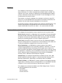
How can servers be protected against power failures? Usually redundant power
supplies and redundant power cords connected to different power lines are used
for basic protection.
The failure of one of these components does not affect the operation of the
server. To protect the system against a complete power loss, an uninterruptible
power supply (UPS) is required. If software such as PowerChute PLUS is
installed on the system and a communication link is set between the UPS and the
server, PowerChute PLUS can stop the applications and shut down the operating
system.
Power
Power
Server
UPS
Power
Communication
Smart signaling cable
Figure 1. UPS with one server
For larger solutions such as a Microsoft Cluster Server (MSCS) configuration, a
single UPS may not provide sufficient protection. The run-time capacity of one
UPS is inadequate in most cases for two servers with shared storage.
Additionally, one UPS is a single point of failure. Thus, you need two or more
UPS units. However, in an MSCS environment with one or two UPS units you
have certain problems:
• Application handling: In an MSCS environment you cannot simply stop an
application; the cluster application must be set to offline with the cluster
administration tool. If the application is stopped by normal procedures (such
as PowerChute PLUS’s Application Shutdown or application-specific stop
procedure), then the application would be considered as failed and restarted
by the cluster resource monitor.
• Server status: If a power loss occurs on one server, a communication about
the status of the other server is required. If only the local server is affected by
the power loss, then it makes sense to move all cluster resources from this
node to the surviving one. Otherwise, if no other node is available or if the
other node will also shut down, then the resources must be set to offline.
• Server power cabling: How are power cables connected? Some servers
have a N+1 redundancy in power supplies. If you connect a server with three
power supplies and three power cords to two power circuits, you have at least
two power supplies on the same circuit. It is possible that this circuit will fail.
With the one remaining power supply, the server will not work. In the case of a
server with two power cords, you could try to connect them to different UPS
units. But then you have the communication problem as described below.
© Copyright IBM Corp. 2001
1
• UPS monitoring: PowerChute PLUS can monitor only one UPS at a time,
independent of the type of communication link to this UPS (serial line or
network). If you attach more than one UPS to a server, then the server cannot
receive signals from all UPS units. Thus, you cannot attach more than one
UPS to a server.
• Storage protection: You must guarantee that the last component in your
cluster to fail is the shared storage, because the cluster service will stop
immediately when it loses access to shared storage.
• Storage power cabling: The shared storage typically consists of more than
one component (RAID controller and multiple drive enclosures). The wrong
order of failure of these components may destroy your RAID arrays. For
example, if a drive enclosure with more than one drive of a RAID-5 array fails
before the RAID controller fails, the RAID controller would mark the whole
array as dead.
In Chapter 3, “UPS configurations for cluster” on page 27, we develop solutions
for these cluster-specific problems.
2
Implementing UPS Configurations with Microsoft Cluster Server
Chapter 2. APC hardware and software background
In the following chapters, we describe some UPS units that are important for
cluster solutions. All described UPS units are by American Power Conversion
(APC). You can also get the Smart UPS units as an IBM option.
For a correct sizing of the UPS capacity you need some background information
on power.
They are different power types in alternate current (AC):
• Real power
• Blind or reactive power
• Apparent power
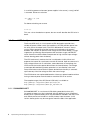
Real power is the actual power dissipated by the load and is calculated as
follows:
P = U ⋅ I ⋅ cos á ϕñ
Where:
P
U
I
Real power
RMS voltage
RMS current
Phase angle (phi) between the current and voltage
ϕ
However, with a purely resistive load, there is no phase shift between current and
voltage, hence cos( ϕ)=1.
P = U⋅I
Blind power, or reactive power, is the power that swings between generator and
load without any work in the load.
Q = U ⋅ I ⋅ sin á ϕñ
Blind power comes into coexistence if there is a phase shift between current and
voltage.
Apparent power is the quadratic sum of real and blind power:
2
2
S = P +Q
S =
2
2
P +Q
2
Chapter 2. APC hardware and software background
3
In a switching power environment (power supplies in the server), a cos( ϕ )=0.707
is assumed. So we can calculate:
S
P = ------------------ = S ⋅ 1, 414
cos ( ϕ )
For better calculating we assume:
P = S ⋅ 1, 5
This was a short introduction to power, but now we will describe the UPS units in
detail.
2.1 Smart-UPS family
The Smart-UPS family is a line-interactive UPS designed to provide clean,
reliable AC power. Under normal line conditions, the UPS provides power from
the utility line to the output loads. The UPS’s bidirectional inverter is always
running. When operating online the inverter runs backwards to charge the
batteries and maintain an optimum float charge on the internal battery. A surge
suppression and filtering network protects the load from surges and EMI/RFI
noise. SmartTrim and SmartBoost compensate for high and low input voltages
without drawing power from the battery.
The UPS continuously monitors the line in anticipation of utility failure and
prepares the inverter for synchronous transfer of the load. Upon occurrence of a
utility voltage failure such as a blackout, severe brownout or overvoltage, the
UPS transfers the load to power derived from the internal battery. The voltage
waveshape delivered during battery operation is a low-distortion sine wave.
Resynchronization and retransfer to power derived from the utility is automatic
upon recovery of the line voltage to within the normal range.
The UPS features user-replaceable batteries. Users can replace batteries without
having to remove power from the loads or send the UPS in for service.
The complete range of the APC Smart-UPS family is available at:
http://www.apcc.com/products/smart-ups/index.cfm
http://www.apcc.com/products/smart-ups_rm/index.cfm
2.1.1 SU2200RMXLINET
SU2200RMXLINET is a rack-mount UPS offering extended run-time (XL).
Increased on-battery run time is obtained with the addition of up to 10 optional
battery packs. Optional battery packs may be added as needed in the field, since
each battery enclosure includes an auxiliary battery input connector. In this
fashion, battery packs may be arranged to meet the needs of the application.
4
Implementing UPS Configurations with Microsoft Cluster Server
Table 1. Technical specifications
VA/W ratings
Maximum 2200 VA or 1600 W
Type of external battery
packs
SU48RMXLBP (8 x 12 V DC and 17 Ah. Nominal system
voltage 48 V DC)
Dimensions: UPS
Height 22.2 cm (5U) x width 48.3 cm x depth 45.1 cm.
(Depth is measured from front of bezel to back of chassis, with
a half-inch allowance for screws and outlets.)
Dimensions: battery pack
Height 17.8 cm x width 48.3 cm x depth 45.7cm
Maximum input current
12 Amps (for nominal line voltages indicated and load
p.f. ~ 0.7 includes load current)
Input resettable circuit
breaker rating
20 Amps
Input wiring devices
IEC 320 C20 16 Amp outlet (1x)
Hardwiring input option
Not available
Output wiring devices
IEC 320 C19 16 Amp outlet (1x)
IEC 320 C13 10 Amp outlet (8x)
Software monitoring and
management
940-0024C black APC serial cable (smart-signaling mode)
Software compatible with
the UPS
PowerChute PLUS 5.1 for Windows NT
PowerChute PLUS 5.2 for Windows NT/2000
Replacement battery
cartridge
RBC11
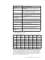
The typical SU2200RMXLINET on-battery run times versus VA load, in minutes
(with SU48RMXLBP) are as follows:
Table 2. Run time SU2200RMXLINET
Load
internal
battery
1 battery
pack
2 battery
packs
3 battery
packs
4 battery
packs
5 battery
packs
1000VA
25
120
225
335
440
550
1200VA
20
91
180
270
360
450
1400VA
16
73
150
225
300
375
1600VA
13
60
120
185
250
315
1800VA
11
52
105
160
220
280
2000VA
9
44
87
140
190
245
2200VA
8
38
75
120
170
215
The UPS is furnished with one input line cord terminated with a CEE7/7 plug and
three 1.8 m long output cords appropriate for connection to equipment with 10
Amp IEC320 appliance receptacles. There is also a set of 19'' rack mounting run
time in the package, together with L-bracket mounts, which adjust for different
depth racks and support the weight of the UPS, allowing the unit to slide in place
and for easy securing of the rack mount ears.
Chapter 2. APC hardware and software background
5
The UPS was designed to mount to any standard EIA RS-310 (ANSI C83.9) 19''
equipment rack.
More information available at:
http://www.apcc.com/products/techspecs/index.cfm?base_sku=SU2200RMXLINET
2.1.2 SU3000RMINET (5U unit)
SU3000RMINET is a rack-mounted UPS with expandable run time via one
battery pack.
Table 3. Technical specifications
VA/W ratings
Maximum 3000 VA or 2250 W
Optional battery pack
SU48BP (4 x 12 V DC and 17 Ah. Nominal system voltage
48 V DC). Only one pack can be connected. The battery pack
itself isn't rack-mountable and must be placed on a supporting
tray behind the UPS (SU035).
Dimensions: UPS
Height 22.2 cm x width 48.3 cm x depth 45.1 cm.
(Depth is measured from front of bezel to back of chassis, with
a half-inch allowance for screws and outlets.)
Battery pack
Height 21.6 cm (5U) x width 17.0 cm x depth 43.9 cm
Maximum input current
15 Amps (for nominal line voltages indicated and load
p.f. ~ 0.7 includes load current)
Input resettable circuit
breaker rating
20 Amps
Input wiring devices
IEC 320 C20 16 Amp outlet (1x)
Hardwiring input option
Not available
Output wiring devices
IEC 320 C19 16 Amp outlet (1x)
IEC 320 C13 10 Amp outlet (8x)
Software monitoring and
management
940-0024C black APC serial cable (smart-signaling mode)
Software compatible with
the UPS
PowerChute PLUS 5.1 for Windows NT
PowerChute PLUS 5.2 for Windows NT/2000
Replacement battery
cartridge
RBC11
The typical SU3000RMINET on-battery run times versus VA load, in minutes
(with SU48BP) are as follows:
Table 4. Run time SU3000RMINET
6
Load
Internal battery
With external battery pack
1000VA
26
73
1200VA
20
58
1400VA
16
42
1600VA
13
35
2000VA
10
25
Implementing UPS Configurations with Microsoft Cluster Server
Load
Internal battery
With external battery pack
2200VA
8
22
2500VA
7
18
3000VA
5
13
The UPS is furnished with one input line cord terminated with a CEE7/7 plug and
three 1.8 m long output cords appropriate for connection to equipment with
10 Amp IEC320 appliance receptacles. There is also a set of 19'' rack mounting
ears in the package, together with L-bracket mounts, which adjust for different
depth racks and support the weight of the UPS, allowing the unit to slide in place
and for easy securing of the rack mount ears.
The UPS was designed to mount to any standard EIA RS-310 (ANSI C83.9) 19''
equipment rack.
More information is available at:
http://www.apcc.com/products/techspecs/index.cfm?base_sku=SU3000RMINET
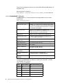
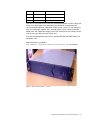
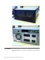
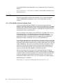
Figure 2. APC Smart UPS 3000 — front view
Chapter 2. APC hardware and software background
7
Figure 3. APC Smart UPS 3000 — rear view
In Figure 2 and Figure 3, you can see the APC Smart UPS 3000 that you can get
as an IBM option. Technical data is identical with the 5U model, but the option to
increase the run time with an additional battery pack is not available.
2.1.3 SU5000RMINET
SU5000RMINET is a rack-mount UPS. The extended run time feature isn't
available for this model.
Table 5. Technical specifications
8
VA/W ratings
Maximum 5000 VA or 3750 W
Dimensions: UPS
Height 22.9 cm (5U) x width 43.9 cm x depth 66.5 cm.
(Depth is measured from front of bezel to back of chassis,
with a half-inch allowance for screws and outlets.)
Maximum input current
30 Amps (for nominal line voltages indicated and load
p.f. ~ 0.7 includes load current)
Input resettable circuit breaker
rating
30 Amps
Input wiring devices
Hardwired only
Hardwiring input option
Yes
Output wiring devices
IEC 320 C19 16 Amp outlet (2x)
IEC 320 C13 10 Amp outlet (8x)
Software monitoring and
management
940-0024C black APC serial cable (smart-signaling mode)
Software compatible with the
UPS
PowerChute PLUS 5.1 for Windows NT
PowerChute PLUS 5.2 for Windows NT/2000
Replacement Battery
Cartridge
2x RBC12
Implementing UPS Configurations with Microsoft Cluster Server
The typical SU5000RMINET on-battery run times versus VA load, in minutes are
as follows:
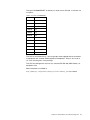
Table 6. Run time SU5000RMINET
Load
Internal battery
1000 VA
64
1200 VA
50
1400 VA
39
1600 VA
32
2000VA
23
2200 VA
20
2500 VA
16
3000 VA
11
3500 VA
10
4000 VA
8
4500 VA
7
5000 VA
5
The UPS is furnished with six 1.8 m long output cords appropriate for connection
to equipment with 10 Amp IEC320 appliance receptacles. There is also a set of
19'' rack mounting ears in the package.
The UPS was designed to mount to any standard EIA RS-310 (ANSI C83.9) 19''
equipment rack.
More information is available at:
http://www.apcc.com/products/techspecs/index.cfm?base_sku=SU5000RMI5U
Chapter 2. APC hardware and software background
9
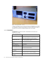
Figure 4. APC Smart UPS 5000 — front view
Figure 5. APC Smart UPS 5000 — rear view
2.2 Symmetra
You cannot buy Symmetra as an IBM option. The Symmetra is available only from
APC.
10
Implementing UPS Configurations with Microsoft Cluster Server
2.2.1 Symmetra Masterframe/Miniframe
The Symmetra is an uninterruptible power array system, designed for large-scale
loads. It provides conditioned, reliable AC power to load equipment, and provides
protection from power blackouts, brownouts, swells, sags, surges and
interference. The Symmetra Power Array system comprises either a Miniframe or
a Masterframe, and a variable set of modules (see 2.2.1.4, “VA ratings” on
page 12). Both battery modules and power modules are available.
A battery module contains 4-12 batteries to increase the run time of a Symmetra
Power Array. A power module has a main intelligence module (2.2.1.2, “Control”
on page 12) and some power supplies that provide power to the battery charger
and the MIM. You can use two or more battery modules, but you must use one
power module. The small modules are Miniframes and the larger modules are
Masterframes.
A Miniframe system can be configured to deliver a maximum output of 8 kVA, and
a Masterframe system can deliver a maximum of 16 kVA.
Figure 6. Symmetra Masterframe and Miniframe
The power processing system delivers conditioned AC output power with a
low-distortion sine wave. Under normal operating conditions, power is received
from the AC main (utility) power source, conditioned by the power processing
system, and delivered to the load equipment. In the event of an AC main power
source failure, the power processing system receives power from the battery
source (battery modules), converts it to conditioned AC, and delivers it to the load
equipment. When the AC main power source is present, the power processing
system also maintains the battery source at full charge.
The power processing system in Symmetra is comprised of one or more power
modules. Each power module contains the electronic components for a complete
4 kVA UPS, including the rectifier, charger, and inverter. When two or more power
modules are present, they operate in parallel, sharing the load equally. By
configuring the system with at least one more power module than is required to
power the load (a redundant power module), Symmetra can sustain a power
module failure and still deliver full power to the load equipment. When the failed
module is identified by the control/user interface system, an alarm is initiated to
notify the user of the module failure. The hot-swappable module can be replaced
by the user, without the need to power down the load equipment.
A Symmetra Miniframe provides bays for up to three power modules, and a
Masterframe provides bays for up to five. This affords the full system capacity
(8 kVA and 16 kVA respectively), plus one redundant power module.
Chapter 2. APC hardware and software background
11
2.2.1.1 Battery source
The battery source is comprised of parallel, hot-swappable, 120 V battery
modules. These are housed in the Symmetra frame, and in an optional XR
Extension Battery frame. A Symmetra Miniframe provides bays for up to two
battery modules, and a Masterframe provides bays for up to four. Both of these
frames can be connected to an XR Extension Battery frame. Additional battery
modules increase battery run time.
2.2.1.2 Control
Symmetra incorporates a main intelligence module (MIM) that continuously
monitors the system. The MIM does the following:
• Coordinates the initial startup of the system
• Transfers it into and out of bypass mode
• Transfers the power source between the main AC power and the battery
source
• Coordinates shutdown operations
• Gathers data about the system components
• Delivers it to the Powerview interface and the computer interface ports
System status monitoring and reporting data includes the current predicted run
time, the status of individual battery and power modules, the size of input and
output voltage, the input and output voltage frequency, and the size and status of
the output load.
2.2.1.3 Alarm condition detection
The control/user interface system monitors Symmetra for alarm conditions. If an
alarm condition is detected, the Powerview user interface initiates an audible and
visual alarm. Alarm conditions include on-battery, low battery, module faults,
overloads, loss of redundancy and a variety of other default and user-defined
events.
More information is available at:
http://www.apcc.com/products/symmetra/index.cfm
2.2.1.4 VA ratings
The Symmetra comes in different VA ratings:
• Miniframe:
4 - 8 kVA
• Masterframe: 8 - 16 kVA
(always + one 4 kVA power module for N+1 redundancy)
12
Implementing UPS Configurations with Microsoft Cluster Server
UPS
UPS
UPS
UPS
UPS
UPS
UPS
UPS
Intelligent
Battery
Battery
Power
8 kVA
31”H x 24”W x 27”D
SYMINI
Intelligent
Battery
Battery
Battery
Battery
Power
16 kVA
Battery
Battery
Battery
Battery
Extended Battery
Battery
Battery
Battery
Battery
Battery
Battery
Battery
Battery
Battery
Battery
Battery
Battery
Extended Battery
45”H x 24”W x 27”D
SYMSTR
18”H x 24”W x 27”D
SYXR4
46”H x 24”W x 27”D
SYXR12
APC part numbers:
•
•
•
•
•
•
•
•
•
SY4KEXI
SY8KI
SY8KEXI
SY12KEXI
SY16KI
SYPM
SYBATT
SYXR4
SYXR12
Miniframe with 1 PM (4 kVA) expandable to 8 kVA redundant
Miniframe with 2 PM (8 kVA) expandable to 8 kVA redundant
Masterframe with 2 PM (8 kVA) exp. to 16 kVA redundant
Masterframe with 3 PM (12 kVA) exp. to 16 kVA redundant
Masterframe with 4 PM (16 kVA) exp. to 16 kVA redundant
Additional power module
Additional battery module
Extended battery frame for up to 4 modules (not included)
Extended battery frame for up to 12 modules (not included)
You can find the IBM part numbers in Appendix C of the IBM Paper Configurator.
This document is available from http://www.pc.ibm.com/support/.
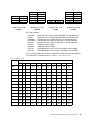
Table 7. Run time chart
VA load
Number of batteries installed
1
2
3
4
5
6
7
8
9
10
12
2000
15
40
66
96
126
162
192
222
258
288
354
3000
9
23
40
58
78
96
120
138
156
180
222
4000
6
15
27
40
53
66
84
96
114
126
156
5000
n/a
11
20
29
40
51
62
72
84
96
120
6000
n/a
9
15
23
31
40
49
58
66
78
96
7000
n/a
7
12
18
25
32
40
47
55
60
79
8000
n/a
6
10
15
21
27
33
40
46
53
66
9000
n/a
n/a
9
13
18
23
28
34
40
46
58
10000
n/a
n/a
7
11
15
20
24
29
34
40
51
12000
n/a
n/a
6
9
12
15
19
23
27
31
40
14000
n/a
n/a
n/a
7
10
12
15
18
22
25
32
15000
n/a
n/a
n/a
6
9
11
14
17
20
23
29
16000
n/a
n/a
n/a
6
8
10
13
15
18
21
27
Chapter 2. APC hardware and software background
13
For recommendations about Symmetra wiring, see the PDF file at the following
address:
http://sturgeon.apcc.com/techref.nsf/umanuals/094362544B00279C8525675C006F
AEE2?OpenDocument
2.3 UPS options
There are many options for UPS units available, such as Interface Expander
Cards or WEB/SNMP Management Cards, which we describe in the next
sections.
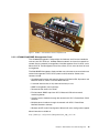
2.3.1 APC AP9607 Interface Expander Card
The UPS Interface Expander (AP9607) is an accessory that provides two
additional computer interface ports for your APC UPS equipped with a SmartSlot
accessory slot. It allows the UPS to work in conjunction with PowerChute PLUS
software to provide safe system shutdown in extended power outages for up to
three network servers or other devices.
Since the computer interface port of the UPS remains available while using the
Interface Expander, it is possible to provide advanced UPS and power
management functions to all protected devices. The Interface Expander draws
power from the UPS. It monitors the UPS and reports power conditions (for
example, On Battery, Low Battery, On Line) to all attached devices.
The communication between an APC UPS and a connected server can be of two
types: simple signaling or smart signaling. A master server is a server connected
to the advanced computer interface port of the UPS via the black smart-signaling
cable (#940-0024C). This server uses PowerChute PLUS, configured for smart
signaling, to monitor and control the UPS. Although the advanced port on the
UPS can provide simple signaling, we strongly recommend using it for smart
signaling with the advanced capabilities of PowerChute PLUS.
Servers connected to the basic ports of the Interface Expander via the grey
simple signaling cable (#940-0020B for Windows NT/Novell/OS2 or 940-0023A
for UNIX systems) use simple signaling with PowerChute PLUS to provide UPS
shutdown capabilities and advanced notification features. If you are running
PowerChute PLUS on these servers, you must configure it for simple signaling.
More information is available at:
http://www.apcc.com/products/management/shareups_smartslot.cfm
14
Implementing UPS Configurations with Microsoft Cluster Server
Figure 7. AP9607 — APC SmartSlot Interface Expander Card
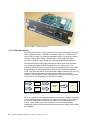
2.3.2 AP9606 Web/SNMP Management Card
The AP9606 Management Card provides the hardware and firmware needed to
connect your APC UPS to a 10 Mbps Ethernet network and use that network for
remote (over the network) management of the Management Card, its UPS, and a
Measure-UPS. The Management Card also allows you to use a terminal for local
management.
The Web/SNMP Management Card provides many features to ease and enhance
network management of APC UPS systems and accessories. Some of the
features include:
• Complete configuration and control of Smart-UPS, Matrix-UPS, Symmetra and
Measure-UPS via a built-in intuitive Web interface
• A console interface that is fully featured and easy to use
• SNMP management (sets and traps)
• Remote console access via Telnet
• Environmental SNMP traps from APC’s Measure-UPS environmental
monitoring device
• Graceful server shutdown through the network with APC’s PowerChute PLUS
software
• Multiple server shutdown through the network with APC’s PowerChute
Network Shutdown software
• Windows 95/NT 4.0 GUI Configuration Wizard with mass configuration support
More information available at:
http://www.apcc.com/products/management/web_snmp_card.cfm
Chapter 2. APC hardware and software background
15
Figure 8. AP9606 — APC Web/SNMP Card
2.3.3 Redundant Switch
The Redundant Switch is a high availability UPS accessory designed to provide
clean, reliable AC power. It provides a seamless transfer to an alternative AC
source when the input is outside the acceptable range. It can withstand zero to
twice the nominal input voltage, while preventing any possibly damaging
transients or gaps in output voltage from reaching the protected equipment.
The Redundant Switch should be used with two identical Smart-UPS models,
thus providing mirrored Smart-UPS protection to your critical loads. The
Redundant Switch transfers the load to the mirrored Smart-UPS unit should the
output voltage from the preferred Smart-UPS unit fall outside the acceptable
range. Transfer of the load to the mirrored UPS happens automatically, ensuring
virtually continuous AC power availability and availability of safe server
shutdown. The Redundant Switch is phase-locked to the utility, and will provide
as seamless a transfer between AC sources as possible.
Phase A
UPS 1
Power
Redundant
Switch
Phase B
UPS 1
Power
Server
Power
Figure 9. Redundant Switch
APC has created this cost-effective method to increase the AC power availability
of your protected network equipment. An important advantage of this solution is
that you can feed power to the two Smart-UPS units from two separate AC
circuits, further increasing system availability. This fault-tolerant product
combination allows monitoring and line filtering of these two separate AC sources
up to 3000VA.
16
Implementing UPS Configurations with Microsoft Cluster Server
The use of a double pole transfer switch by default makes the Redundant Switch
fault tolerant. A single point of failure in the electronics does not cause a dropout
of the output voltage. The transfer switch must select one input or the other,
which are both acceptable, by definition, when a single fault in the Redundant
Switch occurs.
The Redundant Switch is furnished with brackets and slides for mounting in
standard 19" rack systems. Brackets for 23" applications are available as an
accessory.
With the Redundant Switch SU044-1 you have two redundant UPS units.
SU044-1 is designed to work with two identical SU2200RMXLINET or two
SU3000RMINET UPS.
Table 8. Technical specifications
VA ratings
Maximum 3000 VA or 2250 W (2x SU2200RMXLINET or
SU3000RMINET)
Dimensions
Height 4.45 cm (1U) x width 43.2 cm x 23 cm
Maximum input current
16 Amps (for nominal line voltages indicated and load
p.f. ~ 0.7 including load current)
Input wiring devices
IEC 320 C20 16 Amp outlet (2x)
Hardwiring input option
Not available
Output wiring devices
IEC 320 C19 16 Amp outlet (1x)
IEC 320 C13 10 Amp outlet (2x)
EPO switch (emergency
power off)
Yes
Software monitoring and
management
940-0024C black APC serial cable (smart-signaling mode)
Software compatible with the
RS
PowerChute PLUS 5.1 for Windows NT
PowerChute PLUS 5.2 for Windows NT/2000
The Redundant Switch is furnished with one input line cord terminated with a
CEE7/7 plug. There is also a set of 19'' rack mounting ears in the package,
together with L-bracket mounts, which adjust for different depth racks and
support the weight of the RS, allowing the unit to slide in place and for easy
securing of the rack mount ears.
The Redundant Switch was designed to mount to any standard EIA RS-310
(ANSI C83.9) 19'' equipment rack.
More information is available at:
http://www.apcc.com/products/accessories/redundant.cfm
Chapter 2. APC hardware and software background
17
Figure 10. Redundant Switch
For the Redundant Switch SU044-1 we have a sample solution in 3.3.1, “Solution
with multiple UPS units and Redundant Switch” on page 51.
2.4 APC monitoring and management software
2.4.1 PowerChute PLUS
PowerChute PLUS software provides UPS manageability and safe system
shutdown for desktops, workstations, and servers protected by APC UPSs. The
software enables you to monitor and control any APC UPS that has a serial
interface port.
Figure 11. PowerChute PLUS User Interface Module
2.4.1.1 Overview of PowerChute PLUS
PowerChute PLUS provides the following features:
• Orderly shutdown of a network file server or a host computer in the event of an
extended AC power failure
18
Implementing UPS Configurations with Microsoft Cluster Server
• User notification of impending shutdown
• Power event and data logging
• Auto-restart upon power return
• UPS battery conservation features
• Diagnostic and management features, such as scheduled server shutdowns,
interactive/scheduled battery testing, and detailed power quality logging
• Real-time graphical displays of transient data, such as battery voltage, UPS
load, utility line voltage, run time remaining, battery capacity, and battery
voltage
2.4.1.2 PowerChute PLUS Structure
The PowerChute PLUS software consists of two main components:
1. The UPS Monitoring Module, or “server,” communicates with the UPS and
the User Interface Module, logs data and events, notifies users of impending
shutdowns, and when necessary, shuts down the operating system.
2. The User Interface Module consists of the PowerChute PLUS Main Screen
and the System, Logging, Configuration, Diagnostics, and Help menu options.
The User Interface Module lets you access real-time data from the local UPS
Monitoring Module or over a network from UPS Monitoring Modules connected
to other servers. Data includes UPS output, line minimum/maximum voltage,
UPS temperature, output frequency, ambient temperature, humidity, and UPS
status. The User Interface Module also displays event text for the two most
recent events and bar graphs that you can configure to display any three of
the following:
– Utility voltage data
– Battery voltage data
– UPS load data
– Run time remaining
– Battery capacity
– Output voltage
– UPS load
More information is available at:
http://www.apcc.com/products/management/pcp_win2000.cfm
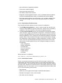
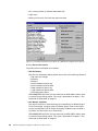
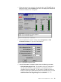
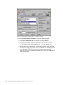
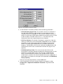
2.4.1.3 PowerChute events
Events are occurrences related to your APC UPS and range in severity from
informational (not critical) to severe (critical). If any of the critical events occur
(see the list below), you must ensure that the Cluster Groups are either moved to
the other node, set offline or the administrator is immediately notified and will take
appropriate action. For most events, you can configure PowerChute PLUS to take
any or all of the following seven actions.
• Log the event.
• Send early warning pop-up messages to specified administrators
• Broadcast messages to users on the network
• Shut down the host computer
Chapter 2. APC hardware and software background
19
• Run a command file (an external executable file)
• Page users
• Send e-mail to notify users that the event occurred
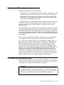
Figure 12. PowerChute PLUS Event Actions Menu (Go to Main Menu-Configuration-Event Actions)
2.4.1.4 Smart UPS events
The critical events monitored are as follows:
• UPS On Battery
The UPS has switched to battery power due to one of the following situations:
– High input line voltage
– Brownout
– Blackout
– Small momentary power sag
– Small momentary power spike
– Deep momentary power sag
– Large momentary power spike
– Simulated power failure
RECOMMENDED ACTION: Run the command file UPS.CMD to either move
or set the Cluster Groups offline. This script is described in Chapter 4, “The
command file UPS.CMD” on page 67.
• Low Battery Condition
The amount of UPS run time remaining has reached the Low Battery Signal
Time. For example, configuring the Low Battery Signal Time to 10 minutes
causes PowerChute PLUS to initiate low battery shutdown when the UPS is
on battery and 10 minutes of run time remain.
RECOMMENDED ACTION: Run the command file UPS.CMD to either move
or set the Cluster Groups offline. This script is described in Chapter 4, “The
command file UPS.CMD” on page 67.
20
Implementing UPS Configurations with Microsoft Cluster Server
• Comm Lost While On Battery
Communication with the UPS has been lost while the UPS is on battery. The
event may be caused by a loose communication cable or, rarely, by a software
conflict, such as an application inadvertently blocking PowerChute PLUS from
monitoring the serial port while the UPS is on battery.
RECOMMENDED ACTION: Run the command file UPS.CMD to either move
or set the Cluster Groups offline. This script is described in Chapter 4, “The
command file UPS.CMD” on page 67.
• PowerChute PLUS Started
PowerChute PLUS UPS monitoring has been started.
RECOMMENDED ACTION: None. After a shutdown, the cluster should be
brought back online manually by the Administrator.
• UPS Battery Is Discharged
The UPS is online, but its battery capacity is low. If power fails, PowerChute
PLUS shuts down the system immediately.
RECOMMENDED ACTION: Immediately notify the cluster administrator. Use
the notify function that was implemented in PowerChute PLUS.
• Lost Communication With UPS
PowerChute PLUS attempts to establish communication with the UPS and
fails, or communication that was established is lost.
RECOMMENDED ACTION: Immediately notify the cluster administrator. Use
the notify function that was implemented in PowerChute PLUS.
• UPS Output Overload
For an APC UPS, the equipment load on the UPS exceeds its rated load
capacity. Reduce the load by unplugging some equipment from the UPS, and
run a self-test.
A Smart-UPS will sound an alarm when loads greater than 107% of its rating
are applied for more than approximately four seconds. Sustained overloads
greater in amplitude than 107% may cause the UPS's input circuit breaker to
trip, depending on the level of overload and its duration. In this case, the UPS
will shut down and not attempt to transfer to battery power in order to protect
its internal circuitry. Note: an overload is detected and indicated independent
of line voltage at 107% of full rated load for all models.
When operating on-battery, the UPS will not attempt to support steady-state
overloads and will shut down after approximately two to five seconds of their
application. However, transient overloads applied while on-battery and lasting
less than one second will be supported up to 150% of the UPS's load rating. In
this case, the output voltage may not be within the specified regulation limits.
The likelihood of the UPS shutting down while operating on-battery due to
transient overload above this rating is increased as the battery becomes
discharged during an extended power outage.
RECOMMENDED ACTION: Immediately notify the cluster administrator.
• Battery Needs Replacing
One or more UPS batteries are heavily discharged and can no longer hold a
full charge. If utility power fails during this condition, an APC runs for less than
half its normal run time.
Chapter 2. APC hardware and software background
21
RECOMMENDED ACTION: Immediately notify the cluster administrator. Use
the notify function that was implemented in PowerChute PLUS.
2.4.1.5 Symmetra events
Apart from the events mentioned above, the Symmetra system features
additional events that are specific to that UPS model only:
• UPS On Bypass: Failure
The Symmetra UPS is on bypass due to a UPS failure.
RECOMMENDED ACTION: Immediately notify the cluster administrator.
• UPS Module Failed
One of the Symmetra power modules has failed.
RECOMMENDED ACTION: Immediately notify the cluster administrator.
• Main Intelligence Module Failed
The main intelligence module has failed.
RECOMMENDED ACTION: Immediately notify the cluster administrator.
• Redundant Intelligence Module Failed
The redundant intelligence module has failed.
RECOMMENDED ACTION: Immediately notify the cluster administrator.
• System Level Fan Failed
The Symmetra fan has failed.
RECOMMENDED ACTION: Immediately notify the cluster administrator.
• Bypass Contactor Failed
The bypass contactor has failed.
RECOMMENDED ACTION: Immediately notify the cluster administrator.
• Input Circuit Breaker Tripped
The input circuit breaker has tripped.
RECOMMENDED ACTION: Immediately notify the cluster administrator.
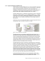
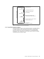
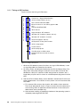
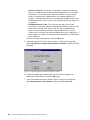
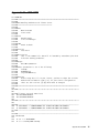
2.4.1.6 PowerChute and UPS delays
Various delays for event actions or shutdown come into play when configuring
PowerChute software. Figure 13 on page 23 explains the sequence in which the
delays are deployed.
22
Implementing UPS Configurations with Microsoft Cluster Server
UPS On Battery event
60 sec
on-battery delay
Total run time available
System Shutdown Starting event
60 sec
shutdown delay
600 sec
turn-off delay
Command File executed (after a
10-second delay)
Operating system shutdown starts
"S" issued to put the UPS in sleep mode
UPS enters sleep mode, powers outlets off
Low Battery Condition event
600 sec
Low battery
warning delay
Battery depleted
UPS switches off completely
Figure 13. PowerChute PLUS event actions and UPS delays
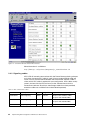
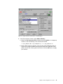
2.4.2 PowerChute network shutdown
PowerChute network shutdown software provides graceful, unattended shutdown
of multiple computer systems (up to 50) over the network. It communicates
across the network with an APC UPS equipped with an AP9606 Web/SNMP
Management Card. A Web browser can be used to quickly and easily configure
individualized server shutdown settings.
Chapter 2. APC hardware and software background
23
Figure 14. PowerChute Network shutdown Web interface
More information is available at:
http://www.apcc.com/products/management/pc_networkshutdown.cfm
2.4.3 Signaling cables
APC UPS will correctly communicate with the PowerChute monitoring software
only when the correct APC cable is used. Using a standard RS232 cable will
result in loss of communication between the UPS and the software. Table 9
shows which APC cable is required for your configuration. APC cables usually
come in the box with the UPS and serve as the software license for the
PowerChute software. Should you need longer cables than those provided,
extension cables are available and can be ordered separately.
Table 9. APC communication cables
Part Number
Description
Color
Length
OS platforms
AP940-0024C
Smart signaling
Black
2 meters
Windows, OS/2, NetWare, UNIX
(except for SGI, AS/400, VMS)
AP940-1524C
Smart signaling
Black
5 meters
Windows, OS/2, NetWare, UNIX
(except for SGI, AS/400, VMS)
AP940-0020B
Simple signaling
Grey
2 meters
Windows, OS/2, NetWare
24
Implementing UPS Configurations with Microsoft Cluster Server
AP940-0023A
Order # AP9823
Simple signaling
Grey
2 meters
UNIX (except True64, Digital,
DEC/OSF, SGI Irix, HP-UX on 800
machines and AS/400)
AP940-0095A
Plug & play cable
smart signaling
Grey
2 meters
Windows 95/98
AP940-0095B
Plug & play cable
smart signaling
Grey
2 meters
Windows 95/98, NT, 2000
AP940-1500
Order # AP9815
Extension cable
Grey
5 meters
Only to be used in connection with a
smart or simple signaling cable
AP9825
Extension cable
Grey
<100 meters
Isolated extension cable
AP940-0019
Simple signaling
Grey
2 meters
Macintosh
AP940-006A
Simple signaling
Grey
2 meters
15-pin male cable for AS/400
AP940-0031A
Simple signaling
Grey
2 meters
9-pin male cable for AS/400
AP940-0103
Null modem cable
Grey
2 meters
Configure Share-UPS/Masterswitch
AP940-0039
Simple signaling
Grey
2 meters
9-25pin for UNIX VMS
AP940-0049A
Smart signaling
Grey
2 meters
SGI Irix Indy or Indygo2 HW
AP940-1000A
signaling cable
Grey
3 meters
Triple chassis to UPS
Redundant Switch to UPS1 + UPS2
AP940-0110A
Powerview cable
Grey
3 meters
Powerview to Symmetra cable
More information is available at:
http://www.apcc.com/products/accessories/cable_kits.cfm
2.5 Power plugs and connectors
IEC320-C13
IEC 320-C14
Figure 15. Cable C12
Chapter 2. APC hardware and software background
25
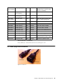
IEC 320-C19
IEC 320-C14
Figure 16. Cable D12
IEC 320-C19
CEE 7/7
Figure 17. Cable
CEE 7/7
IEC 320-C13
Figure 18. Cable
26
Implementing UPS Configurations with Microsoft Cluster Server
Chapter 3. UPS configurations for cluster
There are two different ways to use UPS units:
• Single power line: one UPS for both servers, controllers, and enclosures. This
will be used in small cluster configurations or with a large UPS (Symmetra).
• Double power line: two UPS units, one UPS for each server, controller and
enclosures are connected to both UPS units. This will be used in large data
centers with two independent power lines.
In a complete solution, this would be combined with UPS software that utilizes the
cluster API. Since such software does not exist at present, another solution is
required. A simple command file UPS.CMD is sufficient, but works only for
two-node clusters.
We recommend that the operating system of the cluster is installed in the English
language. We developed the command file, UPS.CMD, with the English version
of Microsoft Windows NT 4.0 Enterprise Edition. The messages may be different
if any other language than English is installed. The command file depends on the
exact spelling of English messages. For use with other languages, UPS.CMD has
to be adapted.
Every time the command file UPS.CMD is used, it makes an output redirection
into a log file LOG.TXT. This log file contains events related to the UPS.
As a test we used an MSCS solution with two IBM Netfinity 8500Rs (8681), an
IBM Netfinity Fibre Channel RAID Controller Unit (3526) with six IBM Netfinity
EXP15 (3520) storage expansion enclosures, and two IBM Netfinity Fibre
Channel hubs (3523). We implemented this cluster with two redundant Fibre
Channel loops. The computer name for the first Netfinity was NF8500L (Netfinity
8500 left), for the second Netfinity NF8500R (Netfinity 8500 right). On both
nodes, Microsoft Windows NT 4.0 Enterprise Edition with Service Pack 5 was
installed. The language of the operating system was English. Two virtual file
servers (VFS) were defined as cluster resources. Each virtual file server had its
own group with the names VFS_A and VFS_B. In each group we defined an IP
address, a network name, a shared disk resource, and a file share.
3.1 General UPS configuration rules
Note: Our solution is based on the command file UPS.CMD. It is mandatory that
the administrator adapt this file according to the cluster configuration. For details,
see Chapter 4, “The command file UPS.CMD” on page 67.
Important
It is important to understand which actions the UPS performs when a power
loss is detected. These issues are discussed in 3.1.1, “Timing of UPS actions”
on page 28. Then we consider UPS capacity planning in 3.1.2, “UPS capacity
planning” on page 29 and recovery in 3.1.3, “Recovery” on page 30.
Chapter 3. UPS configurations for cluster
27
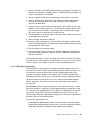
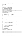
3.1.1 Timing of UPS actions
600 s
Power loss / Signal UPSOnBattery
UPS Tur n Of f Del ay max.
Figure 19 shows the timing of UPS actions.
Run command file UPS.CMD
Move res ources or set offline (approx. 300
sec)
Execute SHUTGUI.EXE
UPS On Battery Delay (5 s ec)
W ait 120 s ec
Begin W indows NT shutdown
W indows NT shutdown (approx. 90 s ec)
W indows NT shutdown finished
Res erved (approx. 90 sec)
UPS powers off the power outlets
UPS in sleep mode
Power restore
UPS wakeup phase
Provide power to UPS outlets
W indows NT boot (c luster resources
offline)
t
Figure 19. Timing of UPS actions
1. When the UPS detects a power line failure, the signal UPSOnBattery is sent
via signaling cables (or network) to the servers.
2. All further actions are delayed as defined by the UPS On Battery Delay. This
delay filters short power outages so they do not shut down the server. We
decided for a delay of 5 seconds to allow enough time for shutdown, but a
longer delay may be useful in case of an accidental power plug removal of the
UPS.
3. After the UPS On Battery Delay, actions defined in PowerChute PLUS for this
event are performed. In our solution, the only action is to run the command file
UPS.CMD.
a. This command file analyzes the situation and handles cluster resources.
The time of 300 seconds shown in Figure 19 means the time necessary to
move or bring offline all application-related resources in the cluster (thus
300 seconds are an example only).
b. After resource handling is completed, shutdown of the operating system is
initiated by executing SHUTGUI.EXE.
28
Implementing UPS Configurations with Microsoft Cluster Server
4. Some commands in UPS.CMD were launched asynchronously. To allow such
operations to complete, we added a delay as a SHUTGUI.EXE parameter. The
value of 120 seconds is an example.
5. After this SHUTGUI.EXE delay, the operating system begins to shut down.
6. From our experience, a Windows NT 4.0 shutdown requires approximately
90 seconds. This depends on the number of remaining (non-clustered)
services and applications.
7. Figure 19 shows a reserve interval of 90 seconds. We used this to get some
flexibility in UPS capacity planning. If any of the time estimates above turned
out to be too low (for example, an operating system shutdown takes longer
than usual), then this reserved time may be used up.
8. The UPS powers off the power outlets and enters sleep mode (monitors input
for reestablishment of power).
9. Some time later, the power is restored.
10.During the UPS wakeup phase, a certain level of recharge must be reached,
and the UPS Wakeup Delay must be passed. Recharge level and delay can be
configured by the administrator.
11.The UPS powers on the power outlets.
12.The servers begin to boot (except when Windows 2000 power management
requires operator intervention). With our solution, application-related cluster
resources are offline.
The time between steps 1 and 8 is limited by the UPS Turn Off Delay. This delay
cannot be set to a value greater than 600 seconds. Thus the sum of all intervals
shown in Figure 19 from step 1 to step 8 must not exceed 600 seconds.
3.1.2 UPS capacity planning
A UPS should have the capacity to manage a complete shutdown, even if the
next power loss occurs shortly after reestablishing power. With a APC UPS, you
can configure to which level the UPS must be charged before going online.
Capacity calculation is based on the shutdown time. The UPS must be able to
provide the total power workload for all components during a complete shutdown.
To get the minimum value for UPS run time, increase the estimated shutdown
time by 10 percent. This takes into account that each battery loses capacity
during its life.
We developed solutions for providing power via one power line see 3.2, “Single
power line solutions” on page 31) or with exploiting power line redundancy (see
3.3, “Solutions with double power lines” on page 51). Depending on the solution
you choose, one or two UPS units are needed. In the case of two units, the
cluster’s power workload is distributed among them, so that each unit provides (in
the ideal case) half of the total workload.
The electrical requirements are:
• An IBM Netfinity 8500R (8681) needs an electrical input in kilovolt-amperes
(kVA) between approximately 0.5 kVA and 2.1 kVA from three power supplies.
(Reference: IBM Netfinity 8500R Hardware Maintenance Manual.)
Chapter 3. UPS configurations for cluster
29
• The IBM Netfinity EXP15 storage expansion enclosure (3520) has an
electrical input between approximately 0.06 kVA and 0.39 kVA from two power
supplies. (Reference: IBM Netfinity EXP15 Storage Expansion Unit Hardware
Maintenance Manual.)
• The electrical input of an IBM Fibre Channel RAID Unit (3526) is similar to an
EXP15. (Reference: IBM Netfinity Fibre Channel Hardware Maintenance
Manual.) The requirement of the IBM Fibre Channel Hub (3523) is
approximately 0.2 kVA.
The electrical requirements depend on the configuration details of the devices
(for example, the number of processor or PCI adapters). More adapters in an IBM
Netfinity cause more electrical input. See http://www.pc.ibm.com/support/ for
details.
Additional components that have to be protected are network hubs or switches for
client access to the cluster. Approximately 0.6 kVA are used in the following
calculation.
Table 10. Total electrical input calculation
Component
Load
Number
Total
IBM Netfinity 8500R (8681)
2.1 kVA
2
4.2 kVA
IBM Netfinity Fibre Channel Hub (3523)
0.2 kVA
2
0.4 kVA
IBM Netfinity Fibre Channel RAID Unit (3526)
0.4 kVA
1
0.4 kVA
IBM Netfinity EXP15 Storage Expansion Unit (3520)
0.4 kVA
6
2.4 kVA
Network devices
0.6 kVA
1
0.6 kVA
8.0 kVA
Our estimated shutdown time is 600 seconds. We added 60 seconds for risks
such as battery aging, so for a solution with one UPS, we need a run time of
660 seconds with 8.0 kVA. For solutions with two UPS units, we need this run
time with 4.0 kVA per unit.
As we see in Chapter 2, “APC hardware and software background” on page 3,
only the APC Symmetra can provide an output of 8 kVA, leaving it the only choice
for single UPS solutions. For example, in the Symmetra run time chart, look on
the line “8 kVA” for a run time of at least 11 minutes. We see that we need
four batteries.
For solutions with two UPS units, the SU5000 is a good choice to provide the
output of 4 kVA. In the SU5000 run-time chart, notice that the estimated run time
with 4 kVA is 8 minutes only. Therefore, in a production environment, the SU5000
is not recommended, and a larger UPS is needed. In our test environment we
decided to use only one EXP15, giving us a run time of 11 minutes.
3.1.3 Recovery
We don’t recommend automatic recovery after a power failure for several
reasons:
• In a data center, a lot of services relay on each other. For example, connection
to a domain controller is needed to start the cluster service. This requires not
only a PDC or BDC, but also stable network connections. Therefore, an
30
Implementing UPS Configurations with Microsoft Cluster Server
administrator intervention is useful to analyze the status of such components
before starting production systems.
• There is a possibility that a resource operation might be aborted by an
operating system shutdown. In case of an aborted operation, you cannot
accurately predict the status of all resources at the moment of restart.
• With Windows 2000, the power management differs from Windows NT 4.0. At
the end of an operating system shutdown, the machine is powered off
automatically. When power is reestablished, the server must be switched on
by pressing the power button.
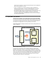
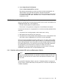
3.2 Single power line solutions
The first thing to consider is that all electric power for the cluster is provided by
one power line (one phase). This may be done via one or two UPS units. (More
than two UPS units per two-node cluster should not be used because each server
can configure or monitor only one UPS at a time.) The only possible scenario is
the failure of this single power line causing shutdown of the cluster.
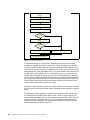
If one UPS is sufficient to supply the whole cluster, then the cabling schema is as
shown in Figure 20.
Communication - Smart-signaling cable
Server 1
Phase A
Cluster
UPS
Server 2
Communication - Simple-signaling cable
Figure 20. Single power line with one UPS
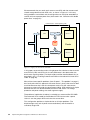
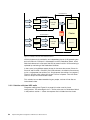
If two UPS units are necessary, then the power cabling for shared storage
equipment needs special attention. As described in Storage power cabling on
page 2, the wrong order of shared storage component failures may destroy RAID
arrays. Thus we have to ensure that all storage components will lose power at the
same moment. But the run time of the two UPS units is always different, even if
they are of the same type, with the same load attached, and with the same
shutdown parameters (because of aging effects).
Chapter 3. UPS configurations for cluster
31
We recommend that you attach each server to one UPS and then connect each
shared storage device to both UPS units, as shown in Figure 21. In this way,
timing problems are avoided, and the configuration can easily be extended to a
solution with two separate power lines (discussed in 3.3, “Solutions with double
power lines” on page 51).
Communication - Smart-signaling cable
UPS
Server 1
Phase A
Cluster
UPS
Server 2
Communication - Smart-signaling cable
Figure 21. Single power line with two UPS units
In this paper, we restrict discussion of single power line solutions to the case with
one UPS only. With two UPS units, the only difference is that both nodes use
black smart-signaling cables. Thus both nodes would be installed identically (as
described in 3.2.4, “Installing PowerChute PLUS on the node with a black serial
cable” on page 35).
Most of the cluster-specific problems (from Chapter 1, “The problem” on page 1)
don’t really exist with this approach; the server status is always the same for both
machines because they have the same power source. For the same reason,
there are no cases to consider for server power cabling. UPS monitoring is simple
because one UPS can be monitored by more than one server. For storage
protection and power cabling, the same arguments apply.
The problem of application shutdown is solved by our command file UPS.CMD.
The command file is started by the Windows NT UPS service after a power
failure. It sets the groups offline and shuts the server down.
This configuration provides a simple solution to all major problems. The
disadvantages are a lack of power source redundancy and the need for a
sufficiently large UPS.
32
Implementing UPS Configurations with Microsoft Cluster Server
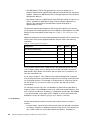
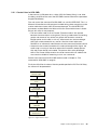
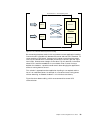
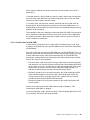
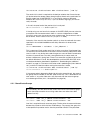
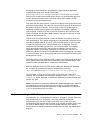
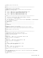
3.2.1 Control flow in UPS.CMD
In the event of a UPS power loss, a delay (UPS On Battery Delay) is set. After
this delay, the UPS service starts the UPS.CMD command file with the parameter
SingleUPSOnBattery.
The main task of the command file UPS.CMD is to call CLUSTER.EXE. This is a
Microsoft Cluster Server utility program installed during cluster setup that can be
used to administer clusters from the command prompt. The CLUSTER.EXE
parameters are described in the Microsoft Cluster Server Administrator’s Guide.
We use this utility for two purposes:
• The local cluster node is set to Paused. (The other node is also paused
because the same script is running there.) Pausing a node means that existing
groups and resources stay online, but groups and resources cannot be
brought online on this node. In this way, we ensure that a resource brought
offline will not be restarted for any reason. Also the cluster node status
PAUSED is an indicator for administrators that the command file takes control.
• Groups that are currently located on this node are brought offline. Again, the
same script is running on the other node and all resources (except quorum
disk and Cluster Group) are handled. The quorum disk cannot be brought
offline. The Cluster Group contains the cluster name and the IP address that
must remain available for executing CLUSTER.EXE commands.
Details of the command file UPS.CMD are discussed in Chapter 4, “The
command file UPS.CMD” on page 67.
Finally the OS will be shut down. After the period specified in UPS Turn Off Delay,
the servers will be powered off.
UPS on battery
abnormal condition
On Battery Delay
in PC+
run UPC.CMD
SingleUPSOnBattery
set local node to
PAUSED
set cluster groups
to OFFLINE
shutdown
Windows NT 4.0
Figure 22. Single UPS flow chart
Chapter 3. UPS configurations for cluster
33
The operating system shutdown is started from the command file, not by using
the PowerChute PLUS Shut Down Server action. When using this action, the
server would be stopped after a maximum delay of 300 seconds. Since the time
necessary to take a cluster resource offline varies, 300 seconds might be too
short. Therefore, the script utilizes the SHUTGUI.EXE tool from the Microsoft
Windows NT Resource Kit CD.
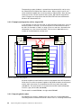
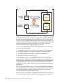
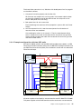
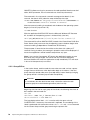
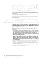
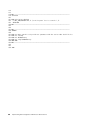
3.2.2 Example configuration with a single UPS
In our example, we use only one UPS, an APC Symmetra Power Array. It has an
electrical output of 16.0 kVA. Our cluster requires an overall electrical input of
8.0 kVA. For example, in Table 7 on page 13 you can see that a Symmetra with
10 batteries has a run time of 53 minutes. The run time is dependent on the
number of installed batteries and the load.
Network
Network
QLogic HBA
QLogic HBA
IBM Netfinity
COM
8500R
IBM Netfinity
8500R
FC HUB
FC HUB
Communications - Smart-signaling cable
IBM Netfinity Fibre Channel
RAID Controller
IBM Netfinity EXP Storage
Expansion Unit
IBM Netfinity EXP Storage
Expansion Unit
IBM Netfinity EXP Storage
Expansion Unit
IBM Netfinity EXP Storage
Expansion Unit
IBM Netfinity EXP Storage
Expansion Unit
Communications - Smart-signaling cable
COM
QLogic HBA
QLogic HBA
IBM Netfinity EXP Storage
Expansion Unit
APC Symmetra Power Array UPS
Figure 23. Single UPS cabling diagram
All power supplies of each Netfinity server are connected to the APC Symmetra
Power Array, as well as the power supplies of the RAID controller, the enclosures,
and the hubs. One server is connected to the UPS via a black serial cable
(940-0024C). The second server is connected to the UPS Interface Expander
Card via a grey serial cable (940-0020B).
The left node is named NF8500L, the right node NF8500R.
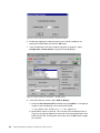
3.2.3 Preparing both nodes
To implement our solution, additional files are necessary, as described below.
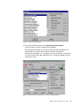
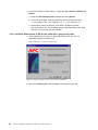
The configuration of PowerChute PLUS is shown in 3.2.4, “Installing PowerChute
34
Implementing UPS Configurations with Microsoft Cluster Server
PLUS on the node with a black serial cable” on page 35 and 3.2.6, “Installing
PowerChute PLUS on the node with a grey serial cable” on page 44.
1. Create a new directory C:\UPS_CMD.
2. Create the command file UPS.CMD in C:\UPS_CMD (you can find the content
of the file in Appendix B, “UPS.CMD” on page 77 or download it from
http://www.redbooks.ibm.com/).
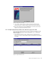
3. Copy the file SHUTGUI.EXE from the Windows NT Resource Kit CD to
C:\UPS_CMD.
As result, you should have a directory similar to Figure 24 on page 35.
C:\>tree ups_cmd /f
Directory PATH listing for volume NTWKS
Volume serial number is 0012FC94 166F:1BD3
C:\UPS_CMD
ups.cmd
shutgui.exe
No subdirectories exist
C:\>
Figure 24. Directory view
3.2.4 Installing PowerChute PLUS on the node with a black serial cable
In 2.4.3, “Signaling cables” on page 24 the differences between black and grey
cables are explained.
1. Install PowerChute PLUS 5.2 for Windows NT 4.0. You can download
PowerChute PLUS from:
http://www.apcc.com/tools/download/
Figure 25. Install PowerChute PLUS - Choose type of installation
Chapter 3. UPS configurations for cluster
35
2. Select the Custom option and click Next. This displays Figure 26.
Figure 26. Install PowerChute PLUS — select components
3. Select the boxes to install the components you wish to install. Select
PowerChute PLUS Client and PowerChute PLUS UPS Service. The other
components are optional. Click Next to display the Select Components
window.
Figure 27. Install PowerChute PLUS — automatic shutdown components
4. Do not check any boxes of these components for automatic application
shutdown. Click Next.
36
Implementing UPS Configurations with Microsoft Cluster Server
Figure 28. Install PowerChute PLUS — automatically detect UPS
5. The window shown in Figure 28 will be displayed. First, make sure that the
smart-signaling cable is connected to the PC interface port of the UPS and to
the serial COM port of the server. The smart-signaling cable is a black cable
with the part number 940-0024C (a short cable) or 940-1524C (a longer
cable).
6. Click the Yes button to automatically detect the UPS. The UPS will be found
by the installation program, and Figure 29 will be displayed.
Figure 29. Install PowerChute PLUS — automatically detect the UPS
7. Your UPS should be discovered correctly. If not, you can select the UPS type
and COM port manually from the pull-down menus. Click Next and Figure 30
will be displayed.
Chapter 3. UPS configurations for cluster
37
.
Figure 30. Install PowerChute PLUS — remote monitoring
8. In this window select the box to enable the PowerChute PLUS remote
monitoring function. For details see the PowerChute PLUS documentation.
9. Finish the installation by clicking Next. If you wish, you can now register your
hardware and software with APC.
3.2.5 Configuring PowerChute PLUS on the node with a black serial cable
Now we configure the time intervals as shown in Figure 19 on page 28, and we
define the actions according to the events described in 2.4.1.3, “PowerChute
events” on page 19.
1. Start PowerChute PLUS. You see a window (Figure 31) with all servers in the
same IP subnet segment where the PowerChute PLUS software is installed.
Figure 31. PowerChute PLUS — monitor server
38
Implementing UPS Configurations with Microsoft Cluster Server
2. Select your server. In our scenario, the second node is the NF8500R with the
black serial cable. Click the Attach button, which will display the PowerChute
PLUS main window shown in Figure 32.
Figure 32. PowerChute PLUS — main window
3. In the PowerChute PLUS main window, select Configuration > UPS
Shutdown Parameters. Figure 33 will be displayed.
Figure 33. UPS Shutdown Parameters window
4. In the UPS Shutdown Parameters window, enter the following parameters:
– UPS Low Battery Signal Time: This condition will occur if the battery is
very old and the UPS can supply power for a short period only (thus
immediate actions are required). It is the minimum number of minutes of
battery run time that the UPS needs to perform the essential tasks of a safe
system shutdown. Possible values are 2, 5, 7, and 10 minutes. We
recommend 10 minutes to get enough time for shutdown.
Chapter 3. UPS configurations for cluster
39
– UPS Turn Off Delay: This period of time begins at power loss. After this
interval, the UPS turns off its output power (independent of any shutdown
completion). If line voltage returns during this period, turning off output
power is canceled (again independent of any shutdown operations in
progress). Possible delay values are 20, 180, 300, and 600 seconds. We
recommend that you set the value as estimated in the time line (Figure 19
on page 28).
– UPS Wakeup Delay (Time): This is the time that the UPS must be
connected to a functioning power line before the attached systems can be
powered up. Possible delay values are 0, 60, 180, and 300 seconds.
Again, we recommend the maximum value of 300 seconds (to avoid
system boot in situations with short-time power return only). Additionally, a
percentage of full capacity for recharge may be specified as UPS Wakeup
Delay (Capacity).
Once you have set the parameters, click the OK button.
5. In the PowerChute PLUS main window (shown in Figure 32 on page 39),
select Configuration > Application Shutdown Parameters. Figure 34 will be
displayed.
Figure 34. Single UPS application Shutdown Parameters window
6. Disable the application shutdown (because this will be handled by the
command file UPS.CMD) and click the OK button.
7. In the PowerChute PLUS main window (shown in Figure 32 on page 39),
select Configuration > Event Actions. Figure 35 will be displayed.
40
Implementing UPS Configurations with Microsoft Cluster Server
Figure 35. Single UPS Run Command File — UPS On Battery
8. In the Event Actions window, select UPS On Battery.
a. Select the Run Command File checkbox and click Options. In the pop-up
window, insert the following in the Command File field:
“C:\UPS_CMD\UPS.CMD” SingleUPSOnBattery >> C:\UPS_CMD\LOG.TXT
b. Set the Wait value to 5 seconds. This wait time (UPS On Battery Delay in
Figure 19 on page 28) before executing the command file prevents short
power failures from shutting down the cluster. Click the OK button, to apply
your choices.
Chapter 3. UPS configurations for cluster
41
Figure 36. Single UPS Run Command File — Low Battery Condition
9. Now select Low Battery Condition in the Event Actions window.
a. Check Run Command File the checkbox and click Options.
b. In the pop-up window, insert the following in the Command File field:
“C:\UPS_CMD\UPS.CMD” SingleUPSOnBattery >> C:\UPS_CMD\LOG.TXT
c. Set the Wait value to 0 seconds. A low battery condition means that the
UPS can only supply the systems for a short period and immediate actions
must take place. This wait time forces immediate execution of the
command file when a low battery condition occurs. Click the OK button to
apply your choices.
42
Implementing UPS Configurations with Microsoft Cluster Server
Figure 37. Single UPS Event Actions
10.In the Event Actions window, select PowerChute PLUS Started.
Clear the check in the Run Command File checkbox.
We strongly recommend that you do not start the cluster automatically. An
administrator has to evaluate the situation and take the required
measurements. Besides, it is mandatory to start the systems in a data center
in a certain order (PDC, BDC, databases, etc.). Usually the MSCS is the last
component to start.
Figure 38. Single UPS Run Command File — Comm Lost While On Battery
Chapter 3. UPS configurations for cluster
43
11.In the Event Actions window shown in Figure 38, select Comm Lost While On
Battery.
a. Select the Run Command File checkbox and click Options.
b. In the pop-up window, insert the following in the Command File field:
“C:\UPS_CMD\UPS.CMD” SingleUPSOnBattery >> C:\UPS_CMD\LOG.TXT
c. Set the Wait value to 0 seconds. If the UPS is on battery and the
communication is lost, an immediate action is required because the state
and the run time of the UPS are unknown.
3.2.6 Installing PowerChute PLUS on the node with a grey serial cable
1. Install PowerChute PLUS 5.2 for Microsoft Windows NT 4.0. You can
download PowerChute PLUS from:
http://www.apcc.com/tools/download/
Figure 39. Install PowerChute PLUS — Choose Type of Installation
2. Select the Custom option and click Next. This displays Figure 40.
44
Implementing UPS Configurations with Microsoft Cluster Server
Figure 40. Install PowerChute PLUS — Select Components to Install
3. Select the boxes of the components you wish to install. Select PowerChute
PLUS Client and PowerChute PLUS UPS Service. The other components
are optional. Click Next to display the Select Components window.
Figure 41. Install PowerChute PLUS — Select Next Components
4. Do not check any boxes of these components for automatic application
shutdown. Click Next.
5. The window shown in Figure 42 will be displayed. First make sure that an
Interface Expander Card is installed in the Symmetra Power Array.
6. Make sure that the simple-signaling cable is connected to a basic monitoring
port of the Interface Expander Card in the Symmetra Power Array and to the
serial COM port of the server. The simple-signaling cable is a grey cable with
the part number 940-0020B.
Chapter 3. UPS configurations for cluster
45
Figure 42. Install PowerChute PLUS — automatically detect UPS parameters
7. The UPS will not be found by the installation program because auto detection
via the simple-signaling cable is not possible. Thus click the No button.
Figure 43 will be displayed.
Figure 43. Select UPS Type and COM Port window
8. Select Back-UPS as the UPS type and the COM port that is connected to the
UPS with the grey serial cable (part number 940-0020B). Click the Next button
and Figure 44 will be displayed.
46
Implementing UPS Configurations with Microsoft Cluster Server
Figure 44. Disable remote monitoring
9. In this window, select the box to enable the PowerChute PLUS remote
monitoring function. For details see the PowerChute PLUS documentation.
10.Finish the installation by clicking the Next button. If you wish, you can now
register your hardware and software with APC.
3.2.7 Configuring PowerChute PLUS on the node with a grey serial cable
Now we configure the time intervals as shown in Figure 19 on page 28, and we
define the actions according to the events described in 2.4.1.3, “PowerChute
events” on page 19.
1. Start PowerChute PLUS. You see a window (shown in Figure 45) with all
servers in the same IP subnet segment where the PowerChute PLUS software
is installed.
Figure 45. Single UPS Monitor Server
Chapter 3. UPS configurations for cluster
47
2. Select your server. In our scenario, the first node is the NF8500L with the grey
serial cable. Click the Attach button, which will display the main window,
shown in Figure 46.
Figure 46. PowerChute PLUS — main window
3. In the PowerChute PLUS main window, select Configuration > Application
Shutdown Parameters. Figure 47 will be displayed.
Figure 47. Single UPS Application Shutdown Parameters
4. In this window, clear the Enable Application Shutdown checkbox to disable the
application shutdown (because this will be handled by the command file
UPS.CMD) and click the OK button.
5. In the PowerChute PLUS main window (Figure 46), now select Configuration
> Event Actions. Figure 48 will be displayed.
48
Implementing UPS Configurations with Microsoft Cluster Server
Figure 48. Single UPS Run Command File — UPS On Battery
6. In the Event Actions window, select UPS On Battery.
a. Select the Run Command File checkbox and click Options. In the pop-up
window, insert the following in the Command File field:
“C:\UPS_CMD\UPS.CMD” SingleUPSOnBattery >> C:\UPS_CMD\LOG.TXT
b. Set the Wait value to 5 seconds. This wait time (UPS On Battery Delay in
Figure 19 on page 28) before executing the command file prevents short
power failures from shutting down the cluster. Click the OK button to apply
your choices.
Chapter 3. UPS configurations for cluster
49
Figure 49. Single UPS Run Command File — Low Battery Condition
7. In the Event Actions window, select Low Battery Condition.
a. Select the Run Command File checkbox and click Options.
b. In the pop-up window, enter the following in the Command File field:
“C:\UPS_CMD\UPS.CMD” SingleUPSOnBattery >> C:\UPS_CMD\LOG.TXT
c. Set Wait to 0 seconds. A low battery condition means that the UPS can
supply the systems for a short period only and immediate actions must take
place. This wait time forces immediate execution of the command file when
a low battery condition occurs. Click the OK button to apply your choices.
Figure 50. Single UPS Event Actions
50
Implementing UPS Configurations with Microsoft Cluster Server
8. Select PowerChute PLUS Started.
Clear the Run Command File checkbox.
We strongly recommend that you do not start the cluster automatically. An
administrator has to evaluate the situation and take the required
measurements. Besides, it is mandatory to start the systems in a data center
in a certain order (PDC, BDC, databases, etc.). Usually the MSCS is the last
component to start.
3.3 Solutions with double power lines
Now let’s consider the case when electric power for the cluster is provided by two
independent power lines, which happens if:
• The data center exploits two power phases.
• The cluster is a long-distance configuration in two different data centers.
In contrast to the case of a single power line, now there are three possible failure
scenarios:
1. One power line is working properly and the other one is failing.
2. Both power lines are failing at the same time.
3. One power line is failing and the second power line fails a short period of time
later (when actions triggered by the first failure are not completed).
There are several possibilities for power cabling, but in all cases, power cabling
for shared storage equipment needs special attention. As described in Storage
power cabling on page 2, the wrong order of shared storage component failures
may destroy RAID arrays. Thus we have to ensure that all storage components
will lose power at the same moment. However, the UPS units may fail
independently. Thus we strongly recommend that you dual-attach all storage
components to both UPS units via separate power cords.
3.3.1 Solution with multiple UPS units and Redundant Switch
Note
Because the Redundant Switch can provide a maximum output of 3 kVA, this
solution can be used only for clusters with a total power consumption of less
than 6 kVA.
Using the APC Redundant Switch (see 2.3.3, “Redundant Switch” on page 16),
you can attach a server redundantly to two power lines. Failure of one power line
is hidden completely.
Chapter 3. UPS configurations for cluster
51
Communication
Communication
Phase A
UPS 1
Power
Redundant
Switch
Phase B
UPS 2
Power
Server 1
Power
Communication
Cluster
Communication
Phase A'
UPS 3
Power
Redundant
Switch
Phase B'
UPS 4
Power
Server 2
Power
Communication
Communication
Figure 51. Multiple UPS units with Redundant Switch
UPS fault tolerance is provided by two independent phases (A, B) powering two
pairs of UPS units. Each pair is connected to an APC Redundant Switch, which
adds fault-tolerance in case one of the UPS or power line fails. UPS monitoring is
replaced by monitoring of the Redundant Switches.
In the case of using different power phases in the same data center (Phase A =
Phase A’ and Phase B = Phase B’), the UPS software is installed in the same way
as for a single power line solution (3.2, “Single power line solutions” on page 31).
The only situation which affects the cluster is loss of all power. Thus the server
status is always the same for both nodes.
This solution has not been tested during our project, and we will not discuss
further details here.
3.3.2 Solution with two UPS units
The power cabling from Figure 52 on page 53 is often used in cluster
configurations. The advantage is that — similar to the use of a Redundant Switch
in the previous section — failure of one power line is hidden from the cluster.
52
Implementing UPS Configurations with Microsoft Cluster Server
Communications - smart-signaling cable
Phase A
UPS 1
Server 1
Cluster
Phase B
UPS 2
Server 2
Communications - smart-signaling cable
Figure 52. Two UPS units without application handling
But connecting the power cords in this way prevents correct application handling.
Communication is possible only between one server and one UPS. Therefore, if a
server receives a UPS signal, software on this server cannot check the power
status of the second UPS. For example, phase B fails. Server 2 gets the signal
from UPS 2. Should server 2 begin to shut down? For this decision, information
about UPS 1 would be needed but is not available. Even if server 2 always
decides for shutdown, a question would remain about bringing the applications
offline or moving them to server 1.
This solution is appropriate when application handling is not required and the
focus is on redundant power. An example is a file server cluster; losing power
without executing an ordered shutdown is a risk for data consistency.
Figure 53 shows better cabling, which we recommend for correct UPS
communication.
Chapter 3. UPS configurations for cluster
53
Communications - smart signaling cable
Phase A
UPS 1
Server 1
Cluster
Phase B
UPS 2
Server 2
Communications - smart signaling cable
Figure 53. Two UPS units with application handling
This setup looks very similar to Figure 52 on page 53. The important difference is
the one-to-one relation between UPS status and server status. In Figure 52, the
status of a server is determined by the status of two UPS units, but the server can
communicate with one UPS only. In this setup, however, each UPS influences the
status of one server only. Each server monitors its own UPS. If the server
receives a power loss signal, it always begins to shut down.
The way to handle applications on this node depends on the status of the other
node. The other node may be:
1. Unaffected by the power failure (remaining available for cluster applications).
2. Unavailable (powered off, crashed, or unresponsive for other reasons).
3. Available but cannot be the target of a resource move operation.
4. Affected by a power loss but still running.
In terms of MSCS, status 1 corresponds to Node Up. This is the only status
where the node can receive cluster resources. Status 2 means Node Down, not
responding to a cluster heartbeat. Status 3 is Node Paused. A paused node may
run cluster applications, but it will not accept more resources than currently
owned. This can be used by the administrator to prevent overload or prepare for
maintenance.
Status 4 is outside of MSCS’s scope, but the time interval between UPS power
loss and node shutdown is similar to Node Paused: The node is still running, but
the node should not start additional applications. Thus we set a node that
received the power loss signal to Node Paused.
Because the two cluster nodes are supplied by independent power lines, there is
a chance that a power loss in one phase causes one node only to shut down.
54
Implementing UPS Configurations with Microsoft Cluster Server
What should a node do with cluster resources that are owned at the time of a
power loss?
If the other node is in status Node Up, then this node is able to get the resources
from the failing node. Because each node losing power sets its status to Node
Paused, we avoid useless resource moves.
In any other case, the resources currently owned by the failing node must be
brought offline. By bringing resources offline we ensure that applications shut
down properly and we prevent unwanted failovers that would be aborted (causing
problems when restarting).
These different cases are handled by the command file UPS.CMD. The command
file is started by the Windows NT UPS service after a power failure. Depending
on whether one node or both nodes are on battery, either a resource move or a
cluster shutdown is performed.
3.3.3 Control flow in UPS.CMD
In the event of a UPS power loss, a delay (UPS On Battery Delay) is set. After
this delay, the UPS service starts the UPS.CMD command file with the parameter
UPSOnBattery.
The main task of the command file UPS.CMD is to call CLUSTER.EXE. This is a
Microsoft Cluster Server utility program installed during cluster setup that can be
used to administer clusters from the command prompt. The CLUSTER.EXE
parameters are described in the Microsoft Cluster Server Administrator’s Guide.
We use this utility for three purposes:
• The local cluster node is paused. Pausing a node means that existing groups
and resources stay online, but groups and resources cannot be brought online
on this node. In this way, we ensure that a resource brought offline will not be
restarted for any reason. Also the cluster node status Node Paused is an
indicator for administrators that the command file takes control.
• Eventually, groups that are currently located on this node are brought offline.
There are two exceptions: the quorum disk cannot be brought offline. The
Cluster Group contains the cluster name and IP address that must remain
available for executing CLUSTER.EXE commands.
• Eventually, groups that are currently located on this node are moved to the
surviving node.
Details of the command file UPS.CMD are discussed in Chapter 4, “The
command file UPS.CMD” on page 67.
Finally the operating system will be shut down. After the period specified in UPS
Turn Off Delay, the servers will be powered off.
Chapter 3. UPS configurations for cluster
55
UPS On Battery abnormal
condition
On Battery Delay in PC+
run UPC.CMD UPSOnBattery
set local node to PAUSED
if remote
node "Up"
no
yes
Delay
if remote
node "Up"
no
yes
move Cluster Groups
set Cluster Groups to offline
shut down Windows NT 4.0
Figure 54. Double UPS flowchart
The flowchart shown in Figure 54 has three branches. The UPS On Battery
condition is signaled by the UPS. PowerChute PLUS recognizes this condition
and starts the UPS.CMD command file with the parameter UPSOnBattery. The
command file sets the node status to Node Paused. Then a branch block contains
three queries with a delay between them. If any query delivers the result that the
remote node is not Node Up, then it is impossible to move any resource to the
remote node. Therefore all groups will be set to offline except quorum disk and
Cluster Group. If both queries deliver the result that the remote node is Node Up,
then all resources will be moved to the remote node including quorum disk and
Cluster Group. After either setting the resources offline or moving them to the
remote node, the operating system shuts down.
The delay is implemented to ensure that if both systems start the script at exactly
the same time, the state of the other node is detected correctly during the second
query.
The operating system shutdown is started from the command file, not by using
the PowerChute PLUS Shut Down Server action. When using this action, the
server would be stopped after a maximum delay of 300 seconds. Since the time
necessary to take a resource offline or move a resource varies, 300 seconds
might be too short. Therefore, the script uses the SHUTGUI.EXE tool from the
Microsoft Windows NT Resource Kit CD.
56
Implementing UPS Configurations with Microsoft Cluster Server
The three failure scenarios in 3.3, “Solutions with double power lines” on page 51
are handled as follows:
1. One power line works properly and the other fails
All resources are moved to the surviving node. If the remote node has been
set manually to Node Paused by the administrator, the script will run the
branch “both power lines are failing”.
2. Both power lines fail at the same time
Each node brings the resources offline (exceptions: quorum disk and Cluster
Group).
3. At first one power line fails, later the second power line fails before all
resource moves are completed
One node begins actions as in scenario 1. Then the second power failure
occurs. Groups that are still on the node with the first failure also go offline.
Groups already moved to the node with the second failure will first go online
and then be taken offline.
3.3.4 Example configuration with two UPS units
We used an MSCS solution with two IBM Netfinity 8500 servers (8681), an IBM
Fibre Channel RAID Controller (3526) with six IBM EXP15 (3520) enclosures and
two IBM Fibre Channel hubs (3523). We installed this cluster with two redundant
Fibre Channel loops.
Network
Network
QLogic A.
QLogic A.
QLogic A.
QLogic A.
COM
IBM Netfinity
COM
8500R
IBM Netfinity
8500R
FC-AL HUB
FC-AL HUB
IBM Netfinity Fibre Channel
RAID Controller
IBM Netfinity EXP Storage
Expansion Unit
IBM Netfinity EXP Storage
Expansion Unit
IBM Netfinity EXP Storage
Expansion Unit
IBM Netfinity EXP Storage
Expansion Unit
IBM Netfinity EXP Storage
Expansion Unit
IBM Netfinity EXP Storage
Expansion Unit
APC Smart UPS
5000
Power 1
Power 2
APC Smart UPS
5000
Figure 55. Double UPS
All power supplies of one Netfinity are connected to one APC SMART-UPS 5000.
The power supplies of the RAID controller and the enclosures are connected to
Chapter 3. UPS configurations for cluster
57
both APC SMART-UPS 5000 for redundancy. The hubs are connected only to one
APC SMART-UPS 5000 because they have only one power supply. Each Netfinity
is connected with its UPS via a black serial cable (940-0024C).
The left node is named NF8500L, the right node NF8500R.
3.3.5 Preparing both nodes
To implement our solution, additional files are necessary, as follows:
1. Create a new directory C:\UPS_CMD.
2. For Windows NT, download the file UPS.CMD as described in Appendix A,
“Downloading the additional material” on page 73. For Windows 2000,
download UPS.CMD.W2K and rename it to UPS.CMD.
3. Download the DELAY3.EXE as described in Appendix A, “Downloading the
additional material” on page 73.
4. Copy the file SHUTGUI.EXE from the Windows NT Resource Kit CD to
C:\UPS_CMD.
As result, you should have a directory similar to Figure 56.
C:\>tree ups_cmd /f
Directory PATH listing for volume NTWKS
Volume serial number is 0012FC94 166F:1BD3
C:\UPS_CMD
ups.cmd
shutgui.exe
delay3.exe
No subdirectories exist
C:\>
Figure 56. Directory view
3.3.6 Installing PowerChute PLUS on both nodes
Each node is connected via a black smart-signaling cable to their corresponding
UPS; thus, the installation is identical on both nodes. The following steps have to
be made on both nodes:
1. Install PowerChute PLUS 5.2 for Windows NT 4.0. You can download
PowerChute PLUS from:
http://www.apcc.com/tools/download/
58
Implementing UPS Configurations with Microsoft Cluster Server
Figure 57. Install PowerChute PLUS — choose type of installation
1. Select the Custom option and click Next. This displays Figure 58.
Figure 58. Install PowerChute PLUS — select components to install
2. Select the boxes to install the components you wish to install. Select
PowerChute PLUS Client and the PowerChute PLUS UPS Service. The
other components are optional. Click Next to display the Select Components
window shown in Figure 59.
Chapter 3. UPS configurations for cluster
59
Figure 59. Install PowerChute PLUS — automatic shutdown components
3. Do not check any boxes of these components for automatic application
shutdown. Click Next. The window shown in Figure 60 will be displayed.
Figure 60. Install PowerChute PLUS — select UPS parameters
4. First, make sure that the current node’s COM port is connected via a
smart-signaling cable to the PC interface port of the corresponding UPS. The
smart-signaling cable is a black cable with the part number 940-0024C (a
short cable) or 940-1524C (a longer cable).
5. Click the Yes button to automatically detect the UPS. The UPS will be found
by the installation program and Figure 61 will be displayed.
60
Implementing UPS Configurations with Microsoft Cluster Server
Figure 61. Install PowerChute PLUS — automatically detect the UPS
6. Your UPS has been discovered correctly. Otherwise you can select the UPS
type and COM port manually from the pull-down menus. Click the Next button
and Figure 62 will be displayed.
.
Figure 62. Install PowerChute PLUS — remote monitoring
7. In this window, check the box to enable the PowerChute PLUS remote
monitoring function. For details see the PowerChute PLUS documentation.
8. Finish the installation by clicking Next. If you wish, you can now register your
hardware and software with APC.
3.3.7 Configuring PowerChute PLUS
Now we configure the time intervals as shown in Figure 19 on page 28, and we
define the actions according to the events as described in 2.4.1.3, “PowerChute
events” on page 19. The following steps have to be made on both nodes:
Chapter 3. UPS configurations for cluster
61
1. Start PowerChute PLUS. You see a window (shown in Figure 63) with all
servers in the same IP subnet segment where the PowerChute PLUS software
is installed.
Figure 63. Double UPS Monitor Server
2. Select the current node and click the Attach button. This will display the
PowerChute PLUS main window, shown in Figure 64.
Figure 64. PowerChute PLUS — main window
3. In the PowerChute PLUS main window, select Configuration > UPS
Shutdown Parameters. Figure 65 will be displayed.
62
Implementing UPS Configurations with Microsoft Cluster Server
Figure 65. UPS Shutdown Parameters window
4. On the Shutdown Parameters window, enter the following parameters:
– UPS Low Battery Signal Time: This condition will occur if the battery is
very old and the UPS can supply power for a short period only (thus
immediate actions are required). It is the minimum number of minutes of
battery run time that the UPS needs to perform the essential tasks of a safe
system shutdown. Possible values are 2, 5, 7, and 10 minutes. We
recommend 10 minutes to get enough time for shutdown.
– UPS Turn Off Delay: This period of time begins at power loss. After this
interval, the UPS turns off its output power (independent of any shutdown
completion). If line voltage returns during this period, turnoff of output
power is canceled (again independent of any shutdown operations in
progress). Possible delay values are 20, 180, 300, and 600 seconds. We
recommend to set the value as estimated in the time line (Figure 19 on
page 28).
– UPS Wakeup Delay (Time): This is the time that the UPS must be
connected to a functioning power line before the attached systems can be
powered up. Possible delay values are 0, 60, 180, and 300 seconds.
Again, we recommend the maximum value of 300 seconds (to avoid
system boot in situations with short-time power return only). Additionally, a
percentage of full capacity for recharge may be specified as UPS Wakeup
Delay (Capacity).
Once you have set the parameters, click the OK button.
5. In the PowerChute PLUS main window (Figure 64 on page 62), select
Configuration > Application Shutdown Parameters. Figure 66 will be
displayed.
Chapter 3. UPS configurations for cluster
63
Figure 66. Double UPS Application Shutdown Parameters window
6. Disable the application shutdown (because this will be handled by the
command file UPS.CMD) and click the OK button.
7. In the PowerChute PLUS main window (Figure 64 on page 62), select
Configuration > Event Actions. Figure 67 will be displayed.
Figure 67. Double UPS Run Command File — UPS On Battery
8. In the Event Actions window, select UPS On Battery.
a. Check the Run Command File checkbox and click Options. In the pop-up
window, insert the following in the Command File field:
“C:\UPS_CMD\UPS.CMD” UPSOnBattery >> C:\UPS_CMD\LOG.TXT
b. Set the Wait value to 5 seconds. This wait time (UPS On Battery Delay in
Figure 19 on page 28) before the command file is executed prevents short
power failures from shutting down the cluster. Click the OK button to apply
your choices.
64
Implementing UPS Configurations with Microsoft Cluster Server
Figure 68. Double UPS Run Command File — Low Battery Condition
9. In the Event Actions window, select Low Battery Condition.
a. Check the Run Command File checkbox and click Options.
b. In the pop-up window, insert the following in the Command File field:
“C:\UPS_CMD\UPS.CMD” UPSOnBattery >> C:\UPS_CMD\LOG.TXT
c. Set the Wait value to 0 seconds. A low battery condition means that the
UPS can only supply the systems for a short period, and immediate actions
must take place. This wait time forces immediate execution of the
command file when a low battery condition occurs. Click the OK button to
apply your choices.
Figure 69. Double UPS Run Command File — PowerChute PLUS Started
10.In the Event Actions window, select PowerChute PLUS Started.
Chapter 3. UPS configurations for cluster
65
Clear the check in the Run Command File checkbox.
We strongly recommend that you do not start the cluster automatically. An
administrator has to evaluate the situation and take the required
measurements. Besides, it is mandatory to start the systems in a data center
in a certain order (PDC, BDC, databases, etc.). Usually the MSCS is the last
component to start.
Figure 70. Double UPS Run Command File — Comm Lost While On Battery
11.In the Event Actions window, select Comm Lost While On Battery.
a. Select the Run Command File checkbox and click Options.
b. In the pop-up window, insert the following in the Command File field:
“C:\UPS_CMD\UPS.CMD” UPSOnBattery >> C:\UPS_CMD\LOG.TXT
c. Set the Wait value to 0 seconds. If the UPS is on battery and
communication is lost, an immediate action is required because the state
and run time of the UPS are unknown.
66
Implementing UPS Configurations with Microsoft Cluster Server
Chapter 4. The command file UPS.CMD
All actions necessary for shutting down a node in the cluster are performed by the
command file UPS.CMD. The command file covers attachment of the cluster to
one or two UPS units. Startup procedures may be implemented as well.
Downloading UPS.CMD
See Appendix A, “Downloading the additional material” on page 73 for
insturctions on how to download UPS.CMD.
In this chapter, we explain the command file’s structure. Understanding of these
internals is essentially because the administrator has to modify the file before
using it. There are four sections that must be changed.
The command file has been designed and tested with Microsoft Windows NT 4.0
Enterprise Edition, English version only. A version for Windows 2000 is also
available. See Appendix A, “Downloading the additional material” on page 73 for
details on how to get them.
The UPS.CMD file is also listed in full in Appendix B, “UPS.CMD” on page 77.
This chapter discusses the main segments of the command file:
• 4.1, “Global Variables in the Command File UPS.CMD” on page 67
• 4.2, “Parameter UPSOnBattery” on page 68
– Parameter UPSOnBattery — case: MoveClusterGroups
– Parameter UPSOnBattery — case: GroupOffline
• 4.3, “Parameter SingleUPSOnBattery” on page 71
• 4.4, “StartUp Parameter” on page 72
4.1 Global Variables in the Command File UPS.CMD
Like most other programs, some variables defined at the beginning of the
command file are used throughout the code. In lines 43 and 44, the names of the
cluster nodes are defined. In our scenario we have chosen NF8500R and
NF8500L.
043 SET NodeAName=NF8500R
044 SET NodeBName=NF8500L
Attention
The node names in lines 43 and 44 must be changed by the administrator.
The node name corresponds to the computer name in Microsoft Windows NT.
The computer name is defined in the system environment variable
COMPUTERNAME. The names have to be defined because the file relies on
variables in order to use the same code on both nodes. This reduces the
administrative efforts necessary to run the script.
Chapter 4. The command file UPS.CMD
67
In lines 49 and 50, the environment variable for the computer name is compared
with variables defined in line 43 and 44.
049 IF %NodeAName% == %COMPUTERNAME% SET TheOtherNodeName=%NodeBName%
050 IF %NodeBName% == %COMPUTERNAME% SET TheOtherNodeName=%NodeAName%
This comparison is used to set the name of the remote node.
In line 56, a check for the start parameter is made. If there is no parameter
provided, then (after a jump to line 188) a message shows the possible start
parameters StartUp, UPSOnBattery and SingleUPSOnBattery.
056 IF s%1 == s GOTO ERROR1
188 :ERROR1
189
190 ECHO You must run this script with one parameter with the action that
should be do!
191 ECHO use StartUp
192 ECHO use UPSOnBattery
193 ECHO use SingleUPSOnBattery
194 GOTO END
The code in lines 57 to 59 analyzes the start parameter and branches to the
corresponding label in the command file.
057 IF %1 == StartUp GOTO StartUp
058 IF %1 == UPSOnBattery GOTO UPSOnBattery
059 IF %1 == SingleUPSOnBattery GOTO SingleUPSOnBattery
If the parameter is wrong, then (after a jump to line 188) the message about
possible start parameters StartUp, UPSOnBattery and SingleUPSOnBattery is
displayed.
4.2 Parameter UPSOnBattery
As explained in 3.2, “Single power line solutions” on page 31, and 3.3, “Solutions
with double power lines” on page 51, the same command file handles
configurations with one UPS as well as two UPS units. In both scenarios,
PowerChute PLUS launches the command file at the UPS on Battery event (after
the UPS On Battery Delay). The startup parameter indicates which type of
configuration has to been handled (for example with two UPS units, see
Figure 66 on page 64).
A parameter value UPSOnBattery means a configuration with two UPS units. This
is explained below. The parameter value SingleUPSOnBattery in the case of a
single UPS is discussed in 4.3, “Parameter SingleUPSOnBattery” on page 71.
If the condition in line 58 is fulfilled, then we have the case of two UPS units. The
code for this case begins on line 89.
As a first step, the node that runs the command file enters Node Paused status
(line 92).
092 CLUSTER . NODE %COMPUTERNAME% /PAUSE
Second, the node checks (line 94) if the remote node has a status of Node Up.
68
Implementing UPS Configurations with Microsoft Cluster Server
094 CLUSTER.EXE %TheOtherNodeName% NODE %TheOtherNodeName% | FIND "Up"
The result of this check is required for the decision whether the Cluster Groups
will be moved to the remote node or brought offline. Note that the code looks for
English output from CLUSTER.EXE. In a non-English version of Microsoft
Windows NT 4.0, this may fail! Thus, if you use another language, you have to
verify the code.
In line 95, the error level of the previous line is analyzed:
095 IF %errorlevel% == 1 GOTO GroupOffline
If the Up string was not found in the output of CLUSTER.EXE, then we make the
assumption that the remote node is either in a status of Node Down or Node
Paused. In every case, the resources must not be moved. The resources have to
be set offline, which is done in line 141 (GroupOffline label).
Otherwise, if the result is that the other node is up, then the node with the name
specified in the variable NodeBName will delay execution for three further
seconds:
097 IF %COMPUTERNAME == %NodeBName%
C:\UPS_CMD\DELAY3 3
This is necessary if both nodes reach line 94 at the same time. If both power lines
fail at exactly the same moment, then there is some uncertainty about which node
status is seen. It may be that one node changes to a status of Node Paused some
fractions of seconds later. To avoid a wrong decision by the other node, we
enforce a difference in timing here. There is no command available to do so from
the default Windows NT shell. We developed the small tool DELAY3.EXE, which
can be downloaded as described in Appendix A, “Downloading the additional
material” on page 73. The status of the other node is probed again (lines 100 and
101), and the final decision about moving the resources is made:
100 CLUSTER.EXE %TheOtherNodeName% NODE %TheOtherNodeName% | FIND "Up"
101 IF %errorlevel% == 1 GOTO GroupOffline
If the remote node is detected as Node Up during the second check, the move of
the groups will be initiated (in line 103: jump to line 116). This is described in the
next section. If any other node status was returned, then the resource groups
must be brought offline (4.2.2, “GroupOffline” on page 70).
4.2.1 MoveClusterGroups
Note
It is mandatory that the administrator enters one line for each resource group
which should be moved to the surviving node when one node shuts down
(below line 125).
126 cluster . GROUP "VFS_a" /MOVETO:%TheOtherNodeName% > NUL
127 cluster . GROUP "VFS_b" /MOVETO:%TheOtherNodeName% > NUL
One line is required for each resource group. The dot after the command cluster
denotes the cluster to which the local node belongs. The name of the group has
to be specified in quotation marks after the parameter GROUP. The parameter
Chapter 4. The command file UPS.CMD
69
/MOVETO initiates moving of a resource to the node specified. Note that we don’t
add a /WAIT parameter; thus all commands are issued asynchronously.
The command in line 136 sends a network message to the domain (in our
scenario, the domain APC) about the steps initiated by the script.
136 NET SEND /DOMAIN:APC "The groups are moved from node %COMPUTERNAME% to
%TheOtherNodeName% and will be shutdown in 2 minutes!"
Now the resource handling is completed, and shutdown of the operating system
begins (in line 137 jump to line 179).
137 GOTO Shutdown
With the application SHUTGUI.EXE from the Microsoft Windows NT Resource
Kit, shutdown of the operating system is initiated finally (line 182).
182 C:\UPS_CMD\SHUTGUI.EXE /L /T:120 "A power loss has occurred !" /C
The command file utilizes SHUTGUI.EXE (instead of the PowerChute PLUS Shut
Down Server action) to ensure that the operating system shutdown begins after
resource handling (independent of PowerChute PLUS timers).
The parameter /L forces the local machine to shut down with a delay of /T
seconds. During shutdown, the message in quotation marks will be displayed. /C
means that applications will be forced to stop without any input.
Note: If you use the /C parameter, NT ignores the application’s option to save
data which may have changed. You will not see any File-Save dialog box
because Windows NT forces the application to stop immediately. This will result
in loss of all data previously not saved.
4.2.2 GroupOffline
In the section above, we discussed the case when one node survives a power
outage. Now we will discuss when both nodes begin to shut down. If the final
query about the remote node status (line 100) doesn’t return Node Up, bringing
the groups offline is initiated (jump to label GroupOffline).
Attention
It is mandatory that the administrator enter a three-line section for each
resource group that should be brought offline (after line 154).
Beginning with line 163 for each group of the cluster, the following lines have to
be inserted in the command file:
163 :off3
164 cluster . GROUP "VFS_a" /OFFLINE /WAIT:30 > NUL
165 IF %errorlevel% == 5023 GOTO off3
The jump backwards to label :off3 is used to verify the return value of
CLUSTER.EXE. If necessary, the command is repeated. The numbering of the
labels is performed with consecutive values. Labels :off1 and :off2 are reserved
for the Cluster Group and the group containing the quorum disk.
70
Implementing UPS Configurations with Microsoft Cluster Server
According to recommendations from Microsoft, there should no application
resources belonging to the Cluster Group (see
http://support.microsoft.com/support/kb/articles/Q168/9/48.ASP). It is not
necessary to set the Cluster Group offline. Hence, it is not required to bring the
Cluster Group online after restart; the cluster name and IP address will be
accessible via network automatically.
The group with the quorum disk is a special case because the quorum disk itself
cannot be brought offline. This does not matter because the quorum disk should
be used for the quorum log only. Thus the quorum disk will not belong to an
application-related resource group. In our example, we created a separate
Quorum group. Another usual way is to move the quorum disk into the Cluster
Group (as default with Windows 2000). However, the quorum resource must be
ignored by the command file.
The dot after the command cluster in line 164 denotes the cluster to which the
local node belongs. The name of the group has to be specified in quotation marks
after the parameter GROUP. As action /OFFLINE takes place. In contrast to the
case of moving groups (4.2.1, “MoveClusterGroups” on page 69), here the
commands are executed synchronously. If the command does not complete
within 30 seconds successfully, the command is aborted. The wait time is
application-specific and must be adjusted to the configuration. The next line
allows a low-level error control: Error code 5023 means that the group is currently
in “Online Pending” status. Setting the group offline can take place as soon as the
pending phase is over.
The command file utilizes SHUTGUI.EXE (instead of the PowerChute PLUS Shut
Down Server action) to ensure that the operating system shutdown begins after
resource handling (independent of PowerChute PLUS timers).
With the application SHUTGUI.EXE from the Microsoft Windows NT Resource
Kit, shutdown of the operating system is initiated finally (line 182).
182 C:\UPS_CMD\SHUTGUI.EXE /L /T:120 "A power loss has occurred !" /C
The parameter /L forces the local machine to shut down with a delay of /T
seconds. During shutdown, the message in quotation marks ("A power loss has
occurred !") will be displayed. /C means that applications will be forced to stop
without any input.
Note: If you use the /C parameter, Windows NT ignores the application’s option to
save data that may have changed. You will not see any File-Save dialog box
because Windows NT forces the application to stop immediately. This will result
in loss of all data previously not saved.
4.3 Parameter SingleUPSOnBattery
As explained in 3.2, “Single power line solutions” on page 31, and 3.3, “Solutions
with double power lines” on page 51, the same command file handles
configurations with one UPS as well as two UPS units. In both scenarios,
PowerChute PLUS launches the command file at the UPS on Battery event (after
the UPS On Battery Delay). The startup parameter indicates which type of
configuration has to been handled (for example with one UPS; see Figure 35 on
page 41).
Chapter 4. The command file UPS.CMD
71
A parameter value SingleUPSOnBattery means a configuration with one UPS.
This is explained below. The parameter value UPSOnBattery in the case of two
UPS units was discussed in 4.2, “Parameter UPSOnBattery” on page 68.
If the condition in line 59 is fulfilled, then there is one UPS. The code for this case
begins on line 107:
107 IF %1 == SingleUPSOnBattery GOTO SingleUPSOnBattery
As the first step, the node that runs the command file enters the Node Paused
status (line 110):
110 CLUSTER . NODE %COMPUTERNAME% /PAUSE
As the second step, all groups are brought offline (jump to label GroupOffline):
112 GOTO GroupOffline
The actions to bring the resource groups offline are the same as described in
4.2.2, “GroupOffline” on page 70.
4.4 StartUp Parameter
In the StartUp section, actions can be defined that have to be performed after the
power is reestablished and the system is restarted. PowerChute PLUS generates
a PowerChute PLUS Started event. You may configure the event action to launch
UPS.CMD with the StartUp parameter.
However, we don’t recommend automatic recovery after a power failure for
several reasons:
• In a data center, a lot of services relay on each other. For example, connection
to a domain controller is needed to start the cluster service. This requires not
only a PDC or BDC, but also stable network connections. Therefore, an
administrator intervention is useful to analyze the status of such components
before starting production systems.
• There is a possibility that a resource operation might be aborted by an
operating system shutdown. According to Microsoft, resource operations are
not atomic (Windows NT 4.0 Enterprise Edition, Release Notes ). In case of an
aborted operation, you cannot accurately predict the status of all resources at
the moment of restart.
• With Windows 2000, the power management differs from Windows NT 4.0. At
the end of an operating system shutdown, the machine is powered off
automatically. When power is reestablished, the server must be switched on
by pressing the power button.
Thus we don’t discuss further details here.
72
Implementing UPS Configurations with Microsoft Cluster Server
Appendix A. Downloading the additional material
The programs and CMD files shown in Appendix B, “UPS.CMD” on page 77 and
Appendix C, “DELAY3.EXE source” on page 81 are also available from the IBM
Redbooks Web server.
Point your Web browser to:
ftp://www.redbooks.ibm.com/redbooks/REDP0402
Case sensative
This FTP URL is case sensative — REDP0402 is in uppercase.
Alternatively, you can go to the IBM Redbooks Web site at:
ibm.com/redbooks
Select the Additional materials and open the directory REDP0402.
Note for IBM employees
If you are a user behind the IBM firewall and you use Microsoft Internet
Explorer, you may not be able to view the files on the FTP site. You may get the
error:
425 Can’t build data connection: Connection refused.
The workaround is to use Netscape Navigator instead.
A.1 Using the additional material
The additional material that accompanies this redpaper is as follows:
File name
delay3.exe
delay3.pas
ups.cmd
ups.cmd.w2k
readme.txt
Description
Program to pause a command file
Pascal source code for delay3.exe
CMD file used to control a cluster UPS, for Windows NT
CMD file used to control a cluster UPS, for Windows 2000
(rename to UPS.CMD)
readme file for this additional material, listed below
A.2 Readme
This file contains additional information to this redpaper. Note: Before you use
this solution in a production environment, you must make comprehensive tests.
A.2.1 Windows NT 4.0
A.2.1.1 UPS.CMD and the StartUp Option
Some tests have shown that it may be useful to use the PowerChute Started
event in PowerChute PLUS to resume the node in the cluster. If the other node
then fails, this node can take over the resources from the failed node.
Appendix A. Downloading the additional material
73
1. In the PowerChute PLUS main window, select Configuration > Event
Actions.
2. In the Event Actions window, select the PowerChute PLUS Started event.
3. Select the RunCommand File checkbox and click Options. Insert the
following in the Command File field:
"C:\UPS_CMD\UPS.CMD" StartUp >> C:\UPS_CMD\LOG.TXT
You must also change the UPS.CMD command file at point 2. Start the cluster
Server. If the Cluster is already started at this moment, you get an error message
that the service already started. Then resume the node.
A.2.1.2 PowerChute 5.2.1
We have written this redpaper with PowerChute PLUS Version 5.2. V5.2.1 is now
available. This version varies somewhat from PowerChute PLUS Version 5.2. If
you use a newer version than V5.2, we recommend that you perform intensive
tests.
A.2.1.3 LOG.TXT
The output of the command file UPS.CMD will be written to
C:\UPS_CMD\LOG.TXT. It may be possible to make this output more useful and
more readable with some time or date commands in the UPS.CMD command file.
A.2.2 Windows 2000
A.2.2.1 ACPI or power management
If you install Windows 2000 on a new model of IBM PC server, Windows 2000 will
automatically install the power management. However, you now have a problem:
PowerChute PLUS shuts Windows 2000 down. After shutting down, Windows
2000 switches the system off. Then, the UPS powers off. As soon as the power
failure is resolved, the UPS puts power on the power outlets but the server will
not start because it was switched off before the UPS turned off the power.
In our opinion you use the function key to disable the power management
function of Windows 2000 during the textmode setup of Windows 2000.
A.2.2.2 The UPS.CMD command file
The UPS.CMD command file as described in this redpaper will not work in
Windows 2000. Instead, you should use UPS.CMD.W2K, rename this file to
UPS.CMD, and configure your UPS as described in this redpaper.
The changes are:
• Enable the operating system shutdown function from PowerChute PLUS 5.2.1
• The script checks which resources are owned by the node and sets them
offline or moves them
• Some small changes for the cluster command tool.
A.2.2.3 DELAY3.EXE
You should use SLEEP.EXE found in the Windows 2000 Resource Kit. This
Microsoft tool works in the same way as DELAY3.EXE. The difference is the use
of resources. SLEEP.EXE does not need as much CPU time as DELAY3.EXE.
74
Implementing UPS Configurations with Microsoft Cluster Server
A hint for Windows 2000 users: The quorum resource is no longer in a separate
resource group. It is now in the Cluster Group.
Appendix A. Downloading the additional material
75
76
Implementing UPS Configurations with Microsoft Cluster Server
Appendix B. UPS.CMD
001
002
003
004
005
006
007
008
009
010
011
012
013
014
015
016
017
018
019
020
021
022
023
024
025
026
027
028
029
030
031
032
033
034
035
036
037
038
039
040
041
042
043
044
045
046
047
048
049
050
051
052
053
054
055
056
057
@ECHO OFF
REM ***************************************************************************
REM
REM UPS Handling with Microsoft Cluster Server
REM ==========================================
REM
REM APC:
REM
Martin Zustak
REM
Peter Fuchs
REM
REM CSG:
REM
Hendrik Ernst
REM
Silvio Erdenberger
REM
REM IBM:
REM
Arwed Tschoeke
REM
REM Version:
REM
2000-08-10
REM
REM Description:
REM
This is the command file that will be launched by PowerChute plus with
REM
different startup parameters.
REM
REM Usage:
REM
UPS.CMD <parameter>
REM
REM where <parameter> is one of the following:
REM
StartUp
REM
UPSOnBattery
REM
SingleUPSOnBattery
REM
REM Warning:
REM
Before using this file in your cluster, you have to adapt the sections
REM
marked with exclamation signs (!!!) for your cluster configuration!
REM
There are four sections (1)-(4) which must be changed!
REM
REM ***************************************************************************
REM !!!!!!!!!!!!!!!!!!!!!!!!!!!!!!!!!!!!!!!!!!!!!!!!!!!!!!!!!!!!!!!!!!!!!!!!!!!
REM (1) Enter your node names here!
SET NodeAName=NF8500L
SET NodeBName=NF8500R
REM !!!!!!!!!!!!!!!!!!!!!!!!!!!!!!!!!!!!!!!!!!!!!!!!!!!!!!!!!!!!!!!!!!!!!!!!!!!
REM --------------------------------------------------------------------------IF %NodeAName% == %COMPUTERNAME% SET TheOtherNodeName=%NodeBName%
IF %NodeBName% == %COMPUTERNAME% SET TheOtherNodeName=%NodeAName%
REM --------------------------------------------------------------------------REM --------------------------------------------------------------------------:CheckParam1
IF s%1 == s GOTO ERROR1
IF %1 == StartUp GOTO StartUp
Appendix B. UPS.CMD
77
058
059
060
061
062
063
064
065
066
067
068
069
070
071
072
073
074
075
076
077
078
079
080
081
082
083
084
085
086
087
088
089
090
091
092
093
094
095
096
097
098
099
100
101
102
103
104
105
106
107
108
109
110
111
112
113
114
115
116
117
78
IF %1 == UPSOnBattery GOTO UPSOnBattery
IF %1 == SingleUPSOnBattery GOTO SingleUPSOnBattery
GOTO ERROR1
REM --------------------------------------------------------------------------REM --------------------------------------------------------------------------:StartUp
REM Set this node in the resume state
NET START “Cluster Server”
CLUSTER . NODE %COMPUTERNAME% /RESUME
REM Set the resources online state
REM !!!!!!!!!!!!!!!!!!!!!!!!!!!!!!!!!!!!!!!!!!!!!!!!!!!!!!!!!!!!!!!!!!!!!!!!!!!
REM (2) Enter one line as shown below
REM for each resource group which should be brought online automatically
REM during startup!
REM CLUSTER . GROUP “Cluster Group” /ONLINE > NUL
REM CLUSTER . GROUP “Quorum”
/ONLINE > NUL
CLUSTER . GROUP “VFS_a”
/ONLINE > NUL
CLUSTER . GROUP “VFS_b”
/ONLINE > NUL
REM !!!!!!!!!!!!!!!!!!!!!!!!!!!!!!!!!!!!!!!!!!!!!!!!!!!!!!!!!!!!!!!!!!!!!!!!!!!
GOTO END
REM --------------------------------------------------------------------------REM --------------------------------------------------------------------------:UPSOnBattery
REM Set this node in the pause state
CLUSTER . NODE %COMPUTERNAME% /PAUSE
CLUSTER.EXE %TheOtherNodeName% NODE %TheOtherNodeName% | FIND “Up”
IF %errorlevel% == 1 GOTO GroupOffline
IF %COMPUTERNAME == %NodeBName%
C:\UPS_CMD\DELAY3 3
C:\UPS_CMD\DELAY3 3
CLUSTER.EXE %TheOtherNodeName% NODE %TheOtherNodeName% | FIND “Up”
IF %errorlevel% == 1 GOTO GroupOffline
GOTO MoveClusterGroups
REM --------------------------------------------------------------------------REM --------------------------------------------------------------------------:SingleUPSOnBattery
REM Set this node in the pause state
CLUSTER . NODE %COMPUTERNAME% /PAUSE
GOTO GroupOffline
REM --------------------------------------------------------------------------REM --------------------------------------------------------------------------:MoveClusterGroups
Implementing UPS Configurations with Microsoft Cluster Server
118 REM Move groups to the other node
119
120 REM !!!!!!!!!!!!!!!!!!!!!!!!!!!!!!!!!!!!!!!!!!!!!!!!!!!!!!!!!!!!!!!!!!!!!!!!!!!
121
122 REM (3) Enter one line as shown below
123 REM for each resource group which should be moved to the surviving node
124 REM when one node shuts down!
125
126
cluster . GROUP “Cluster Group” /MOVETO:%TheOtherNodeName% > NUL
127
cluster . GROUP “Quorum” /MOVETO:%TheOtherNodeName% > NUL
128
cluster . GROUP “VFS_a” /MOVETO:%TheOtherNodeName% > NUL
129
cluster . GROUP “VFS_b” /MOVETO:%TheOtherNodeName% > NUL
130
131 REM !!!!!!!!!!!!!!!!!!!!!!!!!!!!!!!!!!!!!!!!!!!!!!!!!!!!!!!!!!!!!!!!!!!!!!!!!!!
132
133
CLUSTER.EXE %TheOtherNodeName% NODE %TheOtherNodeName% | FIND “Up”
134
IF %errorlevel% == 1 GOTO GroupOffline
135
136
NET SEND /DOMAIN:APC “The groups are moved from node %COMPUTERNAME% to %TheOtherNodeName%
and will be shutdown in 2 minutes!”
137
GOTO Shutdown
138 REM --------------------------------------------------------------------------139
140 REM --------------------------------------------------------------------------141 :GroupOffline
142
143 REM 5005 the other node is not available
144 REM 5023 the group is in the state online pending and could not changed
145 REM 70 the node is in pause status and the resouce could not be set to online
146
147 REM Set groups to the offline state
148
149 REM !!!!!!!!!!!!!!!!!!!!!!!!!!!!!!!!!!!!!!!!!!!!!!!!!!!!!!!!!!!!!!!!!!!!!!!!!!!
150
151 REM (4) Enter one three-line section as shown below
152 REM for each resource group which should be brought offline
153 REM when both nodes shut down!
154
155 REM :off1
156 REM cluster . GROUP “Cluster Group” /OFFLINE /WAIT:30 > NUL
157 REM IF %errorlevel% == 5023 GOTO off1
158
159 REM :off2
160 REM cluster . GROUP “Quorum” /OFFLINE /WAIT:30 > NUL
161 REM IF %errorlevel% == 5023 GOTO off2
162
163 :off3
164
cluster . GROUP “VFS_a” /OFFLINE /WAIT:30 > NUL
165 IF %errorlevel% == 5023 GOTO off3
166
167 :off4
168 cluster . GROUP “VFS_b” /OFFLINE /WAIT:30 > NUL
169 IF %errorlevel% == 5023 GOTO off4
170
171 REM !!!!!!!!!!!!!!!!!!!!!!!!!!!!!!!!!!!!!!!!!!!!!!!!!!!!!!!!!!!!!!!!!!!!!!!!!!!
172
173 NET SEND /DOMAIN:APC “The cluster server is down due to powerfailure! Node %COMPUTERNAME%
will be shutdown in 2 minutes!”
174
GOTO shutdown
175 REM ---------------------------------------------------------------------------
Appendix B. UPS.CMD
79
176
177
178
179
180
181
182
183
184
185
186
187
188
189
190
191
192
193
194
195
196
197
198
80
REM --------------------------------------------------------------------------:Shutdown
ECHO Initiating shutdown
C:\UPS_CMD\SHUTGUI.EXE /L /T:120 “A power loss is occured !” /C
GOTO END
REM --------------------------------------------------------------------------REM --------------------------------------------------------------------------:ERROR1
ECHO You must run this script with one parameter with the action that should be do!
ECHO use StartUp
ECHO use UPSOnBattery
ECHO use SingleUPSOnBattery
GOTO END
REM --------------------------------------------------------------------------:END
Implementing UPS Configurations with Microsoft Cluster Server
Appendix C. DELAY3.EXE source
{************************************************}
{ Delay3 tool
}
{ written by Hendrik Ernst
}
{ C 2000-04-05
}
{************************************************}
uses windos,wincrt,strings;
var TimeDelay,
StartHour, StartMinute, StartSeconds,
DelayHour, DelayMinute, DelaySeconds,
StopHour, StopMinute, StopSeconds,
OldSecond : word;
Hour, Minute, Second, Sec100: Word;
i, temp: word;
Code: Integer;
strHour, strMinute, strSeconds,
strStopHour, strStopMinute, strStopSeconds,
strTime,strStopTime:string;
begin
if ParamCount <> 1 then
begin
writeln('*******************************************************************************');
writeln('* Written by Hendrik Ernst
*');
writeln('* Version 2000040703
*');
writeln('* C 2000-04-07
*');
writeln('*******************************************************************************');
writeln('* No or too many parameters!
writeln('*
writeln('* Please use the following syntax:
writeln('* delay xxx
writeln('* where xxx are the seconds that should be waited.
writeln('* The maximum time is 65000 Seconds
*');
*');
*');
*');
*');
*');
writeln('*******************************************************************************');
end
else
begin
{ Get text from command line }
Val(ParamStr(1), TimeDelay, Code);
{ Error during conversion to integer? }
if code <> 0 then
Writeln('Error at position: ', Code)
else
if (TimeDelay > 0) AND (TimeDelay < 65001) then
begin
Writeln('Value = ', TimeDelay);
GetTime(Hour, Minute, Second, Sec100);
StartHour:=Hour;
StartMinute:=Minute;
StartSeconds:=Second;
DelayHour:= TimeDelay div 3600;
DelayMinute:=(TimeDelay - DelayHour * 3600) div 60;
DelaySeconds:=(TimeDelay - DelayHour * 3600 - DelayMinute * 60);
Appendix C. DELAY3.EXE source
81
StopSeconds:=Second + DelaySeconds;
Temp := 0;
if StopSeconds >= 60 then
begin
StopSeconds := Stopseconds - 60;
Temp := 1;
end;
StopMinute:=Minute + DelayMinute + Temp;
Temp := 0;
if StopMinute >= 60 then
begin
StopMinute := StopMinute - 60;
Temp := 1;
end;
StopHour:=Hour + DelayHour + Temp;
Temp := 0;
if StopHour >= 24 then
begin
StopHour := StopHour - 24;
Temp := 1;
end;
str(Hour,strHour);
str(Minute,strMinute);
str(Second,strSeconds);
strTime:=strHour+ strMinute+ strSeconds;
str(StopHour,strStopHour);
str(StopMinute,strStopMinute);
str(StopSeconds,strStopSeconds);
strStopTime:=strStopHour+ strStopMinute+ strStopSeconds;
while (strTime <> strStopTime) do
begin
GetTime(Hour, Minute, Second, Sec100);
if OldSecond <> Second then write('.');
OldSecond := Second;
str(Hour,strHour);
str(Minute,strMinute);
str(Second,strSeconds);
strTime:=strHour+ strMinute+ strSeconds;
end;
donewincrt;
end
else
begin
writeln('*******************************************************************************');
writeln('* Written by Hendrik Ernst
*');
writeln('* Version 2000040703
*');
writeln('* C 2000-04-07
*');
writeln('*******************************************************************************');
writeln('* No or too many parameters!
writeln('*
writeln('* Please use the following syntax:
writeln('* delay xxx
82
Implementing UPS Configurations with Microsoft Cluster Server
*');
*');
*');
*');
writeln('* where xxx are the seconds that should be waited.
writeln('* The maximum time is 65000 Seconds
*');
*');
writeln('*******************************************************************************');
end;
end;
{donewincrt;}
end.
Appendix C. DELAY3.EXE source
83
84
Implementing UPS Configurations with Microsoft Cluster Server
Appendix D. Referenced documents
• IBM Netfinity 8500R Hardware Maintenance Manual (8681-4RY, 4RG, 5RY,
5RG, 6RY, and 6RG), available from:
ftp://ftp.pc.ibm.com/pub/pccbbs/pc_servers/37l5123.pdf
• IBM Netfinity EXP15 Storage Expansion Unit Hardware Maintenance Manual
(Type 3520), available from
ftp://ftp.pc.ibm.com/pub/pccbbs/pc_servers/10l9839.pdf
• IBM Netfinity Fibre Channel Hardware Maintenance Manual, available from
ftp://ftp.pc.ibm.com/pub/pccbbs/pc_servers/19k2481.pdf
• Microsoft KB document, Information About the Cluster Group, available from:
http://support.microsoft.com/support/kb/articles/Q168/9/48.ASP
• Microsoft Cluster Server Administrator’s Guide, available from: ???????????
Appendix D. Referenced documents
85
86
Implementing UPS Configurations with Microsoft Cluster Server
Appendix E. Special notices
This publication is intended to help customers implement uninterruptible power
supplies in a Microsoft Cluster Server environment. The information in this
publication is not intended as the specification of any programming interfaces that
are provided by Netfinity servers. See the PUBLICATIONS section of the IBM
Programming Announcements for more information about what publications are
considered to be product documentation.
References in this publication to IBM products, programs or services do not imply
that IBM intends to make these available in all countries in which IBM operates.
Any reference to an IBM product, program, or service is not intended to state or
imply that only IBM's product, program, or service may be used. Any functionally
equivalent program that does not infringe any of IBM's intellectual property rights
may be used instead of the IBM product, program or service.
Information in this book was developed in conjunction with use of the equipment
specified, and is limited in application to those specific hardware and software
products and levels.
IBM may have patents or pending patent applications covering subject matter in
this document. The furnishing of this document does not give you any license to
these patents. You can send license inquiries, in writing, to the IBM Director of
Licensing, IBM Corporation, North Castle Drive, Armonk, NY 10504-1785.
Licensees of this program who wish to have information about it for the purpose
of enabling: (i) the exchange of information between independently created
programs and other programs (including this one) and (ii) the mutual use of the
information which has been exchanged, should contact IBM Corporation, Dept.
600A, Mail Drop 1329, Somers, NY 10589 USA.
Such information may be available, subject to appropriate terms and conditions,
including in some cases, payment of a fee.
The information contained in this document has not been submitted to any formal
IBM test and is distributed AS IS. The use of this information or the
implementation of any of these techniques is a customer responsibility and
depends on the customer's ability to evaluate and integrate them into the
customer's operational environment. While each item may have been reviewed by
IBM for accuracy in a specific situation, there is no guarantee that the same or
similar results will be obtained elsewhere. Customers attempting to adapt these
techniques to their own environments do so at their own risk.
Any pointers in this publication to external Web sites are provided for
convenience only and do not in any manner serve as an endorsement of these
Web sites.
The following terms are trademarks of the International Business Machines
Corporation in the United States and/or other countries:
AS/400
e (logo)®
IBM
Netfinity
â
© Copyright IBM Corp. 2001
OS/2
Redbooks
Redbooks Logo
87
The following terms are trademarks of other companies:
Tivoli, Manage. Anything. Anywhere.,The Power To Manage., Anything.
Anywhere.,TME, NetView, Cross-Site, Tivoli Ready, Tivoli Certified, Planet Tivoli,
and Tivoli Enterprise are trademarks or registered trademarks of Tivoli Systems
Inc., an IBM company, in the United States, other countries, or both. In Denmark,
Tivoli is a trademark licensed from Kjøbenhavns Sommer - Tivoli A/S.
C-bus is a trademark of Corollary, Inc. in the United States and/or other countries.
Java and all Java-based trademarks and logos are trademarks or registered
trademarks of Sun Microsystems, Inc. in the United States and/or other countries.
Microsoft, Windows, Windows NT, and the Windows logo are trademarks of
Microsoft Corporation in the United States and/or other countries.
PC Direct is a trademark of Ziff Communications Company in the United States
and/or other countries and is used by IBM Corporation under license.
ActionMedia, LANDesk, MMX, Pentium and ProShare are trademarks of Intel
Corporation in the United States and/or other countries.
UNIX is a registered trademark in the United States and other countries licensed
exclusively through The Open Group.
SET, SET Secure Electronic Transaction, and the SET Logo are trademarks owned
by SET Secure Electronic Transaction LLC.
Other company, product, and service names may be trademarks or service marks
of others.
88
Implementing UPS Configurations with Microsoft Cluster Server