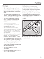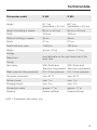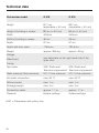
1
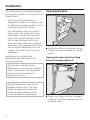
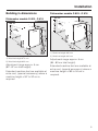
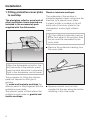
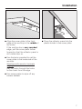
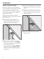
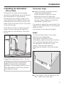
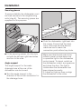
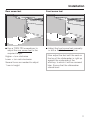
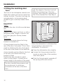
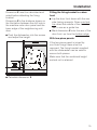
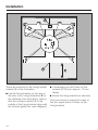
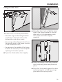
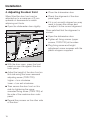
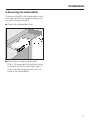
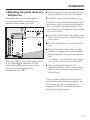
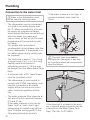
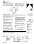
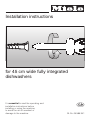
Installation instructions
for 45 cm wide fully integrated
dishwashers
It is essential to read the operating and
installation instructions before
installing or using the machine,
to avoid the risk of accident or
damage to the machine.
G
M.-Nr. 05 585 941
These installation instructions apply to several different dishwasher models.
Model numbers in this booklet refer to the model designation specified on the
data plate on the machine (and not the description on the control panel).
The data plate is located on the right hand side of the door when open.
The model numbers quoted refer only to the basic model number, e.g. the
G 603 SC-Vi is described as the G 603.
It is essential to read the "Warning and Safety Instructions" in the Operating
Instruction booklet before installing the dishwasher.
2
Contents
Installation . . . . . . . . . . . . . . . . . . . . . . . . . . . . . . . . . . . . . . . . . . . . . . . . . . . . . . . 4
Opening the door. . . . . . . . . . . . . . . . . . . . . . . . . . . . . . . . . . . . . . . . . . . . . . . . . . . 4
Opening the door when the fixing bracket has been taken off: . . . . . . . . . . . . . 4
1. Fitting protective cover plate to worktop . . . . . . . . . . . . . . . . . . . . . . . . . . . . . . . 6
2. Building the dishwasher into a niche . . . . . . . . . . . . . . . . . . . . . . . . . . . . . . . . . . 9
Dishwasher height . . . . . . . . . . . . . . . . . . . . . . . . . . . . . . . . . . . . . . . . . . . . . . . 9
Slides . . . . . . . . . . . . . . . . . . . . . . . . . . . . . . . . . . . . . . . . . . . . . . . . . . . . . . . . . 9
Securing pieces . . . . . . . . . . . . . . . . . . . . . . . . . . . . . . . . . . . . . . . . . . . . . . . . 10
3. Fitting the matching door front. . . . . . . . . . . . . . . . . . . . . . . . . . . . . . . . . . . . . . 12
4. Adjusting the door front . . . . . . . . . . . . . . . . . . . . . . . . . . . . . . . . . . . . . . . . . . . 16
5. Securing the dishwasher . . . . . . . . . . . . . . . . . . . . . . . . . . . . . . . . . . . . . . . . . 17
6. Adjusting the door springs . . . . . . . . . . . . . . . . . . . . . . . . . . . . . . . . . . . . . . . . 18
7. Matching the plinth facia of a kitchen run . . . . . . . . . . . . . . . . . . . . . . . . . . . . . 19
Electrical connection . . . . . . . . . . . . . . . . . . . . . . . . . . . . . . . . . . . . . . . . . . . . . . 20
Plumbing. . . . . . . . . . . . . . . . . . . . . . . . . . . . . . . . . . . . . . . . . . . . . . . . . . . . . . . . 22
Connection to the water inlet . . . . . . . . . . . . . . . . . . . . . . . . . . . . . . . . . . . . . . . . . 22
Drainage . . . . . . . . . . . . . . . . . . . . . . . . . . . . . . . . . . . . . . . . . . . . . . . . . . . . . . . . 23
Venting the drainage system . . . . . . . . . . . . . . . . . . . . . . . . . . . . . . . . . . . . . . 23
Special accessories . . . . . . . . . . . . . . . . . . . . . . . . . . . . . . . . . . . . . . . . . . . . . . . 24
Technical data . . . . . . . . . . . . . . . . . . . . . . . . . . . . . . . . . . . . . . . . . . . . . . . . . . . 25
3
Installation
This dishwasher is specially designed
for integration under a worktop run in a
fitted kitchen.
Opening the door
– The front of the dishwasher is
designed to take a front panel. It can
be fitted with a base unit door front to
match the rest of the kitchen.
– The dishwasher does not have a
plinth facia. The plinth area of the
dishwasher needs to be covered
either with a plinth facing to match
the kitchen furniture or with one
which can be ordered as a special
accessory. The separate plinth facia
can be height adjusted to suit the
kitchen. The plinth return is freely
adjustable.
^ Hold one corner of the upper fixing
bracket and pull towards you (small
arrow).
Instructions for installing the
dishwasher are described in the
following sections.
Opening the door when the fixing
bracket has been taken off:
,To ensure stability, these
dishwashers must only be installed
under a continuous worktop which
must be securely screwed to
neighbouring units.
,The dishwasher must not be
installed under a hob. The high
radiant temperatures which are
sometimes generated by a hob
could damage the dishwasher.
^ Insert your finger into the T-shaped
opening in the door opener and pull
the door open.
4
Installation
Building in dimensions
Dishwasher models G 803 - G 818
Dishwasher models G 603 - G 618
1) Machine height 890 mm
2) Machine height 840 mm
1) Machine height 870 mm
2) Machine height 820 mm
Adjustment range approx. 5 cm
(82 - 87 cm total height).
Extended machine feet are available at
extra cost, (special accessory) where a
machine height of 87 to 92 cm is
required.
Adjustment range approx. 5 cm
(84 - 89 cm total height).
Extended machine feet are available at
extra cost, (special accessory) where a
machine height of 89 to 94 cm is
required.
5
Installation
1. Fitting protective cover plate
to worktop
The plexiglass relfector panel and all
other installation items required are
included in the accessories pack
supplied with the dishwasher.
Wood or laminate worktops:
The underside of the worktop is
protected against steam rising from the
machine by a special cover plate.
A plastic holder is located on the left
hand side of the cover plate for the
dishwasher’s control light reflector
panel.
,If two different materials meet up
at the front edge of the worktop, then
the join must be concealed by the
cover plate.
^ Remove the protective backing from
the cover plate.
When the dishwasher is built-in, the
left hand side of the reflector panel
must be sited above the in-operation
light in the dishwasher control panel.
The procedure for fitting the reflector
panel will depend on the type of
worktop.
On wood and laminate worktops the
reflector panel is fitted together with the
protective cover plate.
The reflector panel is fitted without the
protective cover plate on granite and
marble worktops.
6
^ Squeeze sealant from the tube
supplied all the way along the hollow
moulding in the cover plate.
Installation
^ Align the cover plate to the front
edge of the worktop in the middle of
the niche.
If the worktop has a very rounded
edge, pull the cover plate further
forward so that the reflector panel is
still visible later on.
^ Press the reflector panel into the
plastic holder in the cover plate.
^ Use the tacks supplied to nail the
cover plate to the underside of the
worktop.
Worktops with wood or laminate
edging:
Nail the tacks through the holes
further back from the edge.
^ Use soapy water to wipe off any
excess sealant.
7
Installation
Granite or marble worktops:
Worktops made from hard materials
such as granite or marble do not need
the cover plate for protection. The
cover plate is only used as a guide for
marking the position for the reflector
panel plastic holder.
^ Stick the doublesided adhesive strip
supplied onto the back of the plastic
holder.
^ Remove the protective foil from the
adhesive strip and stick the holder to
the underside of the worktop at the
marked position.
Keep the cover plate in case the
dishwasher is ever fitted under another
type of worktop.
^ First, remove the protective foil
covering the plastic holder for the
reflector panel and then take the
holder out of the cover plate.
^ Press the reflector panel into the
plastic holder.
^ Align the cover plate to the front
edge of the worktop in the middle of
the niche. Draw around the cut-out
for the plastic holder.
If the worktop has a very rounded
edge, pull the cover plate further
forward so that the reflector panel is
visible later.
8
Installation
2. Building the dishwasher
into a niche
Connection to water and drainage
should be sited beside and not behind
the dishwasher for accessibility.
Connections are usually made in the
area under the sink. Many kitchen unit
manufacturers provide a cut-out in the
base of the sink base unit for the hoses
to be fed through.
If the base unit has no opening and if
there is not an opening through the
plinth area for connections, one must
be cut.
Dishwasher height
^ Adjust the height manually before
installing the dishwasher.
Leave a space of approx. 5 mm
below the worktop to allow the
dishwasher to be pushed back easily
into the recess. Make sure that the
dishwasher stands level.
It is easier to adjust the screw feet if the
weight of the dishwasher is not bearing
down on them.
If possible tip the machine slightly.
Slides
You will find the slides in the upper
basket of the dishwasher.
They make installation of the
dishwasher easier and protect the floor
from possible damage when moving
the appliance into and out of the
recess. They are also used for
adjusting the height of the rear screw
feet.
Suggested dimensions: 60 x 110 mm.
,There must be no electrical
sockets behind the dishwasher.
Danger of overheating and fire risk if
the dishwasher were to be pushed
up against a plug.
^ Fit the slides - with the ratchet at the
rear - under the screw feet.
9
Installation
Securing pieces
To ensure stability, the dishwasher must
be fixed securely to the neighbouring
units (step 5). Two securing pieces are
supplied for this purpose.
^ Push the dishwasher right back into
the recess. Ensure that the drain
hose, inlet hose and the electric
cable are laid to reach the
connection point without any kinks.
^ Fit the securing pieces into the slots
on both the left and right hand sides
and turn to the side.
Angle support
The angle support for the water
drainage hose at the rear of the
dishwasher can be turned.
^ Turn the angle support in the
direction of the on-site connection for
the drainage hose.
10
Make sure that the left side of the
reflector panel is sited above the
in-operation light in the dishwasher
control panel. To check, switch on
the dishwasher, select a programme
and close the door. The light is
visible when the dishwasher has
been aligned correctly.
If it does not light up then re-align
the dishwasher in the niche.
Installation
Rear screw feet
Front screw feet
^ Use a TORX T20 screwdriver to
adjust the rear screw feet to the
required height.
^ Adjust the front screw feet manually
or with a flat blade screwdriver.
Higher = turn clockwise
Lower = turn anti-clockwise
Several turns are needed to adjust
1 mm in height.
Now adjust the feet until the seal on
the top of the dishwasher is right up
against the underside of the
worktop, to which it will be screwed
later. Ensure that the dishwasher
stands level.
11
Installation
3. Fitting the matching door
front
The front of the dishwasher needs to be
fitted with a base unit front to match the
kitchen furniture. This door front may be
a single panel or a two-piece panel,
divided to give a dummy drawer facia
line.
,The weight of the door front will
affect the functioning of the door
springs. After fitting it is essential for
this to be checked out. See Step 6.
Dimensions:
Width:
to match the door of a 45 cm wide base
unit.
Total height:
Height of a full base unit front, or with a
two-piece panel, height of shorter unit
front plus gap plus dummy drawer
facia.
Thickness:
18 mm in the areas where the fixing
bracket is screwed on.
A fixing bracket must be fitted to the
rear of the door front panel. This is then
used for attaching the door front panel
to the door outer panel on the machine.
When the dishwasher is delivered the
fixing bracket is secured to the
dishwasher. To remove it:
A door handle must be fitted to the front
of the door front before the fixing
bracket is fitted.
Position the door handle to match
others in the kitchen. It should be at
drawer height in the centre of the panel.
^ Loosen the fixing screws (see thin
arrow) on each side of the machine
outer door panel.
The door handle fixing screws must
be countersunk, to avoid any
protrusions at the rear of the door
front.
12
^ Open the dishwasher door slightly.
^ Push the fixing bracket upwards off
the sprung bolts and remove.
Installation
Dimension X must be calculated and
noted before attaching the fixing
bracket.
Dimension X is the distance shown on
the illustration between the drill hole in
the machine outer door panel and the
lower edge of the neighbouring unit
door.
^ Push the dishwasher into the recess
and adjust the height.
Fitting the fixing bracket to a door
front
^ Lay the door front down with the rear
side facing upwards. Draw a vertical
line down the middle of the door front
rear to use as a guide line.
^ Mark dimension X onto the rear of the
door front, up from the bottom edge.
With two-piece panels:
If the two-piece panel is joined by
non-flush fixings these must be
removed. The fixing bracket supplied
with the dishwasher can be used to
secure both pieces.
Make sure that the combined height
worked out is retained.
^ Calculate dimension X.
13
Installation
There are notches on the fixing bracket,
marked a in the illustration.
^ Lay the fixing bracket on the rear of
the door front, using dimension X for
the distance from the bottom, and so
that the notches marked a in the
middle of the fixing bracket align with
the vertical guide line, (see diagram).
14
^ If necessary pre-drill holes for the
screws (Ø 2.5 mm, approx. 10 mm
deep).
^ Screw the fixing bracket on securely.
Only one screw is required in each of
the four upper pairs of holes on the
fixing bracket.
Installation
Fitting the door front
The door front is correctly fitted when:
– the lower lugs on the fixing bracket
rest firmly in the lower slits of the
dishwasher outer door panel,
^ Hang the door front so that the lower
lugs of the fixing bracket fit into the
lower slits of the dishwasher outer
door panel, and draw slightly
upwards.
– the prongs of the fixing bracket lie on
the sprung bolts in the upper corners
of the dishwasher door,
– the recess in the middle of the fixing
bracket fits securely in the T-shaped
opening in the door opener.
^ Open the dishwasher door slightly.
^ Slide the prongs of the fixing bracket
over the sprung bolts and press into
place.
^ Press the front panel against the door
and downwards, so that the prongs
grip behind the sprung bolts.
15
Installation
4. Adjusting the door front
^ Close the dishwasher door.
When fitted the door front can be
adjusted up to a maximum of 2 mm
upwards or downwards to match
adjoining unit fronts.
^ Check the alignment of the door
panel again.
^ Open the dishwasher door slightly.
^ If it is not correctly aligned you may
need to loosen the screws and
re-adjust it to the correct alignment.
Once satisfied that the alignment is
correct:
^ Open the dishwasher door.
^ Tighten all fixing screws (upper
screws, TORX T20) at the sides.
^ Plug fixing screw and height
adjustment screw recesses with the
plastic stoppers supplied.
^ With the door open, press the front
panel on one side against the door
outer panel.
^ Adjust the height of the door front on
this side using the lower recessed
adjusting screw (TORX T20).
higher = turn clockwise
lower = turn anti-clockwise
^ Then secure the door front on this
side by tightening the upper
recessed fixing screw (TORX T20) at
the side of the machine door outer
panel.
^ Repeat the process on the other side
of the door.
16
Installation
5. Securing the dishwasher
To ensure stability, the dishwasher must
be fixed securely to neighbouring units
using the fixing brackets.
^ Open the dishwasher door.
^ Screw the countersunk screws
(3.5 x 15) supplied through the fixing
brackets on the left and right hand
sides into the neighbouring units to
secure the dishwasher.
17
Installation
6. Adjusting the door springs
^ Half open the dishwasher door.
The door springs are correctly adjusted
when the door remains stationary when
left open at 45 °.
The door springs are easier to adjust
when the door is only half open than
when it is fully open.
If the door drops down, then the door
springs need to be tightened.
If it closes then the springs need to be
loosened.
The adjusting screw is located in the
upper front strip at the left hand side of
the dishwasher.
Please note:
If the the door front is too heavy for the
door springs (i.e. the door falls open)
then stronger springs should be fitted.
Please contact your Miele dealer or the
Miele Spare Parts Department for
advice.
18
^ Adjust the door spring with a Torx
T20 or a 1 x 5.5 mm screwdriver until
it is correctly balanced:
- Turn clockwise = tighten
- Turn anti-clockwise = loosen.
Installation
7. Matching the plinth facia of a
kitchen run
^ Place the plinth facia directly in front
of the kitchen run but do not attach.
The plinth area of the dishwasher is
normally covered with a plinth run
matching the kitchen furniture.
^ Carefully open the dishwasher door.
If the door front comes into contact with
the kitchen plinth when the dishwasher
door is opened the plinth facia in the
area behind the dishwasher door needs
to be cut to size.
^ To do this mark where the edge of the
door front comes into contact with the
plinth facia.
^ Cut the plinth facia to size along this
line.
The height (H) of the plinth facia in front
of the dishwasher depends on the
plinth return (R) and how much the
door front extends below the
dishwasher door (P).
^ Place the plinth facia in front of the
kitchen run again and check whether
the dishwasher door can be opened
fully.
If it cannot, trim the plinth facia again
until to the correct size is achieved.
^ Secure the plinth facia to the
adjacent kitchen units in accordance
with kitchen furniture manufacturer’s
instructions.
If your kitchen does not have a plinth
run matching the kitchen furniture, the
plinth area can be covered with a
separate plinth kit, available at extra
cost (special accessory).
19
Electrical connection
,Please follow the installation
instructions carefully.
All electrical work should be carried
out only by a suitably qualified and
competent person, in strict
accordance with national and local
safety regulations.
Ensure power is not supplied to the
appliance while installation work is
being carried out.
This dishwasher is supplied with a
mains cable and moulded plug ready
for connection to an a.c. single phase
supply, (230 -240 V 50 Hz for the UK
and Australia) via a fused plug and
suitable switched socket which is easily
accessible after installation.
^ The voltage, rated load and fuse
rating are given on the data plate
located on the right hand side of the
door. Please ensure that these match
the household mains supply.
For extra safety it is advisable to install
a residual current device (RCD), with a
trip current of 30 mA (in accordance
with DIN VDE 0664, VDE 0100 Section
739).
^ Do not connect via an extension lead.
Danger of overheating.
,If the connection cable is
damaged it must be replaced with a
complete connection box and cable
by a Miele approved service
technician only.
Important
If this machine is fitted with a
non-rewireable plug (BS 1363) and the
socket outlets are not suitable for the
plug supplied or if the existing plug
needs to be replaced by a new one, the
old plug will need to be cut off and an
appropriate plug fitted. The fuse carrier
and the fuse should be removed from
the old plug and disposed of.
The plug cut from the cable should then
be disposed of and on no account be
inserted into any socket elsewhere in
the house (electric shock hazard).
The fuse cover must be refitted when
changing the fuse, and if the fuse cover
is lost, the plug must not be used until a
suitable replacement is obtained. The
colour of the correct replacement cover
is that of the coloured insert in the base
of the plug, or the colour that is
embossed in words on the base of the
plug (as applicable to the design of
plug fitted).
The correct fuse rating of the
replacement fuses that are ASTA
approved to BS 1362 should be fitted.
Replacement fuse covers may be
purchased from your local electrical
supplier or Miele Service Agent.
20
Electrical connection
The wires in the mains lead are
coloured in accordance with the
following code:
Green/yellow = earth
Blue
= neutral
Brown
= live
If the colours of the wires in the mains
lead of this appliance do not
correspond with the coloured markings
identifying the terminals of your plug,
proceed as follows:
^ The wire which is coloured green and
yellow must be connected to the
terminal in the plug which is marked
with the letter E or by the earth
symbol z or coloured green, or
green and yellow.
^ The wire which is coloured blue must
be connected to the terminal in the
plug which is marked with the letter N
or coloured black.
^ The wire which is coloured brown
must be connected to the terminal in
the plug which is marked with the
letter L or coloured red (UK), or
marked with the letter A
(AUSTRALIA).
WARNING:
THIS APPLIANCE
MUST BE EARTHED
21
Plumbing
Connection to the water inlet
,Water in the dishwasher must
not be used as drinking water.
– The dishwasher may be connected
to a cold or hot water supply, max.
60 °C. When connected to a hot water supply all programme stages
which would otherwise be carried out
with cold water (pre-wash and
interim rinse) as well as the Pre-wash
programme will be carried out with
hot water.
On models with recirculation
condensation drying please note that
if your dishwasher is connected to a
hot water supply drying results may
be impaired.
– The inlet hose is approx. 1.5 m long;
a longer hose (4 m), or a 1.5 m long
flexible metal hose tested to
withstand pressure of 140 bar may
be bought from the Miele Spare Parts
Dept.
If the water pressure is too high, a
pressure reducer valve must be
fitted.
!The inlet hose must not be
shortened or damaged in any way
as it contains electrical components
(see illustration).
– A stopcock with a 3/4 " male thread
must be provided on site.
– The dishwasher is constructed to
comply with DVGW regulations, and
may be connected to a suitable
supply without an extra non-return
valve if national regulations allow
this.
– The water pressure (flow pressure at
the take-off point) must be between
0.3 and 10 bar.
If the water pressure is too low the
Water "inlet" or "inlet / drain" light
(depending on model) may light up,
(see "Problem solving guide" in the
Operating Instruction booklet).
22
If the stopcock is situated in the worktop, a special angle connector can be
ordered from the Miele Spare Parts
Dept. (Part No. 04 274 820).
Plumbing
Drainage
Venting the drainage system
– The machine drainage system is
fitted with a non-return valve, which
prevents dirty water from flowing
back into the machine via the drain
hose.
^ Open the dishwasher door fully.
– The dishwasher is supplied with an
approx. 1.5 m long flexible drain hose
with an internal diameter of 22 mm.
– The drain hose can be extended
using a connection piece and an
extra drain hose, (up to max. 4
metres).
If the site drain connection is situated
lower than the guide path for the
bottom basket rollers in the open door
the drainage system must be vented.
Otherwise a siphoning effect during a
programme can cause the machine to
empty itself of water.
To vent:
– A hose clip is supplied for
connecting the drain hose to the
on-site drainage outlet.
– The connection socket on the
dishwasher can be turned. The hose
can thus be laid to the right or left
without needing to loosen the hose
clip supplied.
– The drain system must not exceed 4
metres. The drain pump has a
maximum delivery head of 1 metre.
– The on-site water pipe connection for
the drain hose may be designed to fit
more than one diameter of hose. The
connection socket must be
shortened if it juts too far into the
drain hose. Otherwise the drain hose
can become blocked.
^ Cut off the top of the vent valve in the
wash cabinet.
– The drain hose must not be
shortened.
– Ensure that the drain hose is laid so
that it is free from kinks.
23
Special accessories
You would like to...
Then you need...
... build the dishwasher into a kitchen which
does not have a matching plinth run
...a separate plinth kit
available in: white
black
... adjust the height of the dishwasher to
...kit with extended machine feet
between 87 cm and 92 cm (G 603 - G 618) or
between 89 cm and 94 cm (G 803 - G 818)
24
Technical data
Dishwasher model
G 603
G 803
Height
81.7 cm
(adjustable + 5.0 cm)
84.7 cm
(adjustable + 5.0 cm)
Height of building in recess
82 cm (+ 5.0 cm)
84 cm (+ 5.0 cm)
Width
44.8 cm
44.8 cm
Width of building in recess
45 cm
45 cm
Depth
57 cm
57 cm
Depth with door open
115.5 cm
120.5 cm
Weight
approx. 47 kg
approx. 47.5 kg
Voltage
Rated load
see data plate on the right hand side of the
open door
Fusing
Test marks
VDE, Radio and
VDE, Radio and
Television suppressed Television suppressed
Water pressure (flow pressure)
0.3 - 10 bar pressure
0.3 - 10 bar pressure
Hot water connection
max. 60 °C
max. 60 °C
Delivery head
max. 1 m
max. 1 m
Drainage length
max. 4 m
max. 4 m
Connection cable
approx. 1.7 m
approx. 1.7 m
Capacity
8 place settings
9 place settings
# SC = Dishwasher with cutlery tray
25
Technical data
Dishwasher model
G 618
G 818
Height
81.7 cm
(adjustable + 5.0 cm)
83.7 cm
(adjustable + 5.0 cm)
Height of building in recess
82 cm (+ 5.0 cm)
84 cm (+ 5.0 cm)
Width
44.8 cm
44.8 cm
Width of building in recess
45 cm
45 cm
Depth
57 cm
57 cm
Depth with door open
115.5 cm
120.5 cm
Weight
approx. 48.5 kg
approx. 49 kg
Voltage
Rated load
see data plate on the right hand side of the
open door
Fusing
Test marks
VDE, Radio and
VDE, Radio and
Television suppressed Television suppressed
Water pressure (flow pressure)
0.3 - 10 bar pressure
0.3 - 10 bar pressure
Hot water connection
max. 60 °C
max. 60 °C
Delivery head
max. 1 m
max. 1 m
Drainage length
max. 4 m
max. 4 m
Connection cable
approx. 1.7 m
approx. 1.7 m
Capacity
8 place settings
9 place settings
# SC = Dishwasher with cutlery tray
26
27
Alteration rights reserved (NovoPlus Vi45) / 2006
M.-Nr. 05 585 941 / 01
en - GB