1
TRANSISTORIZED INVERTER
INSTRUCTION MANUAL
e
VFD SETUP SOFTWARE
FR-SW1-SETUP-WE
-Windows (English) Version-
OVERVIEW
1
FUNCTIONS
2
ERROR
INDICATIONS
3
APPENDICES
4
INTRODUCTION
Thank you for choosing the Mitsubishi Transistorized VFD Setup Software.
This instruction manual gives handling information and precautions for use of this software.
Incorrect handling might cause an unexpected fault. Before using this product, please read this manual carefully to
use it to the optimum.
Please forward this manual to the end user.
When reading this manual, note the following:
• This manual is written on the basis that Windows® 95 (English version) is the operating system.
• The [return] and [enter] keys are represented by the
key.
• Drive D is described as the CD-ROM drive and Drive C as the hard disk drive.
• In keyboard operation, simultaneous pressing of keys is indicated by "+".
Example: Pressing the [Alt] and [G] keys simultaneously is indicated by (Alt+G).
• The screens, parameter names, set values and so on given in this manual are written on the basis of the FRA500 series. When using the inverter of any other series, refer to the instruction manual of the used inverter.
Trademarks
• Microsoft and Windows are registered trademark or trademark of Microsoft Corporation in the United States and/
or other countries.
1) The formal name of Windows 95 is Microsoft® Windows® 95 operating system.
2) The formal name of Windows 98 is Microsoft® Windows® 98 operating system.
3) The formal name of Windows NT® is Microsoft® Windows NT® operating system.
4) The formal name of Windows® 2000 is Microsoft® Windows® 2000 operating system.
5) The formal name of Windows® Me is Microsoft® Windows® Me operating system.
•
•
•
•
6) The formal name of Windows® XP is Microsoft® Windows® XP operating system.
The DOS/V personal computer is a registered trademark of IBM Corporation.
The "Mitsubishi Transistorized VFD Setup Software" is a registered trademark of Mitsubishi Electric Corporation.
The copyright and other rights of this software all belong to Mitsubishi Electric Corporation.
No part of this manual may be copied or reproduced without the permission of Mitsubishi Electric Corporation.
Other company and product names herein are the trademarks or registered trademarks of their respective owners.
For Maximum Safety
• Mitsubishi vector inverters are not designed or manufactured to be used in equipment or systems in situations
that can affect or endanger human life.
• When considering this product for operation in special applications such as machinery or systems used in passenger transportation, medical, aerospace, atomic power, electric power, or submarine repeating applications,
please contact your nearest Mitsubishi sales representative.
• Although this product was manufactured under conditions of strict quality control, you are strongly advised to
install safety devices to prevent serious accidents when it is used in facilities where breakdowns of the product
are likely to cause a serious accident.
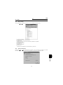
CONTENTS
1 OVERVIEW
1.1
Before Using This Software ................................................................................ 2
1.1.1
1.2
Packing list ................................................................................................................................ 2
Preparations for Startup...................................................................................... 3
1.2.1
1.2.2
System configuration ................................................................................................................. 3
Installing the Setup Software ..................................................................................................... 4
2 FUNCTIONS
2.1
2.2
Machine analyzer (for FR-V500 series only) ........................................................................... 37
Saving, Reading and Printing the Files ........................................................... 42
2.8.1
2.8.2
2.8.3
2.8.4
2.9
Test Running ........................................................................................................................... 35
Auto Tuning ............................................................................................................................. 35
Advanced Function............................................................................................ 37
2.7.1
2.8
VFD Status .............................................................................................................................. 33
Diagnosis................................................................................................................................. 33
Test Running ...................................................................................................... 35
2.6.1
2.6.2
2.7
Data Display ............................................................................................................................ 20
Meter Display........................................................................................................................... 21
Oscilloscopes .......................................................................................................................... 21
Alarm History ........................................................................................................................... 23
Trace Oscilloscopes (for FR-V500 series only) ....................................................................... 24
Diagnosis ............................................................................................................ 33
2.5.1
2.5.2
2.6
All List Format.......................................................................................................................... 14
Functional List Format ............................................................................................................. 17
Individual List Format .............................................................................................................. 18
Basic Settings.......................................................................................................................... 19
Monitor ................................................................................................................ 20
2.4.1
2.4.2
2.4.3
2.4.4
2.4.5
2.5
System Settings....................................................................................................................... 11
Communication Settings.......................................................................................................... 12
Environmental Setting ............................................................................................................. 13
Parameter ........................................................................................................... 14
2.3.1
2.3.2
2.3.3
2.3.4
2.4
File types ................................................................................................................................. 42
Saving method......................................................................................................................... 42
Reading the file........................................................................................................................ 42
Printing .................................................................................................................................... 42
Help ..................................................................................................................... 43
2.9.1
2.9.2
Help contents........................................................................................................................... 43
Version information.................................................................................................................. 43
3 ERROR INDICATIONS
3.1
45
Error codes ......................................................................................................... 46
3.1.1
3.1.2
Error code lists......................................................................................................................... 46
Panel-displayed errors............................................................................................................. 46
4 APPENDICES
4.1
7
Starting the VFD Setup Software........................................................................ 8
Settings................................................................................................................. 9
2.2.1
2.2.2
2.2.3
2.3
1
47
Supplementary Software ................................................................................... 48
4.1.1
4.1.2
4.1.3
Introduction .............................................................................................................................. 48
Parameter files ........................................................................................................................ 48
Parameter file edit software (PREDITE) .................................................................................. 49
1
OVERVIEW
This chapter provides the fundamental "overview" for use of this
product.
Always read the instructions before using this software.
1.1 Before Using This Software ...........................................2
1.2 Preparations for Startup.................................................3
When using this software to make communication with the inverters, set a
value other than 0 in Pr. 122 "communication check time interval" on the
inverter's operation panel. When using the FR-A5NR, set any value other
than 0 in Pr. 336 "communication check time interval", and when using the
FR-S500 series, set any value other than 0 in the communication parameter
n6 (336) "communication check time interval".
(Refer to the inverter instruction manual for the setting method.)
1
2
3
4
1
Before Using This Software
1.1 Before Using This Software
• This software can be used effectively as a support tool for operations from startup to maintenance of the Mitsubishi transistorized inverter. The following functions can be performed efficiently on the Windows® screen of a personal computer.
⋅ System setting function
⋅ Parameter editing function
⋅ Monitoring function
⋅ Diagnosis function
⋅ Test running function
⋅ File management function
⋅ Advanced function
⋅ Help function
1.1.1
Packing list
After unpacking, check that the following items are contained in the package:
Item
Quantity
CD-ROM
Instruction manual
1 disk
1 book
2
Preparations for Startup
1.2 Preparations for Startup
1.2.1
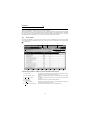
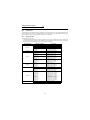
System configuration
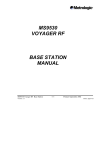
The following devices are required to use the VFD Setup Software. Configure the system in accordance with the
instruction manuals of the corresponding devices.
2)
3)
1)
Mouse
VFD Setup Software
Converter *1
Communication option used
*2
PU connector used *2
Connection cable
RS-485/RS-422
Connection cable
Connector: RJ45 connector
Example: Tyco Electronics Corporation 5-554720-3
Cable: Cable in compliance with EIA568
(such as 10BASE-T cable)
Example: Mitsubishi Cable Industries, Ltd.,
SGLPEV-T 0.5mm×4P
(Twisted pair cable, 4 pairs)
Printer cable
Commercially available
printer
(ESC/P compatible)
Multidrop link system
Termination resistor
Distribution terminal
FR-A5NR
Power supply
NFB
Inverter
Inverter
Inverter
Inverter
Inverter
4) Inverters
Motors
*1: A converter commercially available is required when the personal computer uses the RS-232C port.
<Example of a commercially available product>
Model: FA-T-RS40 Converter (Model with connectors and cable is also available)
Mitsubishi Electric Engineering Co., Ltd.
*2: The PU connector or FR-A5NR (FR-A500 (L) / F500 (L) / V500 series) can be used to make communication.
(Refer to the corresponding instruction manual for details.)
Model, Specifications, Etc.
1) Personal computer
2) Mouse
3) Setup software
4) Inverter
One on which Windows® 95, Windows® 98, Windows NT®, Windows® 2000, Windows® Me or
Windows® XP (English version) operates
Mouse which can be connected to the personal computer
VFD Setup Software (FR-SW1-SETUP-WE)
FR-A520 (-NA), FR-A540 (-NA) (-EC) (-CH),
FR-A520L-75K, 90K, FR-A540L-75K to 280K (-NA) (-EC), FR-A560-NA,
FR-E520-0.1K to 7.5K (-NA), FR-E540-0.4K to 7.5K (-NA) (-EC) (-CH),
FR-E520S-0.1K to 0.75K, FR-E520S-0.4K to 2.2K-EC (-CH), FR-E510W-0.1K to 0.75K (-NA),
FR-F520-0.75K to 55K, FR-F540-0.75K to 55K (-EC) (-CH),
FR-S520-0.1K to 3.7K-R, FR-S540-0.4K to 3.7K-R (-NAR) (-ECR) (-CHR),
FR-S520S-0.1K to 1.5K-R, FR-S520S-0.2K to 1.5K-ECR (-CHR), FR-S510W-0.1K to 0.75K-R
FR-V520, FR-V540
3
1
OVERVIEW
The converter cable cannot connect two or more inverters (the computer and inverter are
connected on a 1:1 basis). Since the product is packed with the RS-232C cable and RS-485 cable
(10BASE-T + RJ-45 connector), the cable and connector need not be prepared separately.
Preparations for Startup
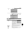
[Connection example between converter and inverter (PU connection port)]
Personal computer
(RS-232C)
Connector
coupling
1.2.2
Inverter
(PU connection port)
FA-T-RS40
Connector
coupling
Installing the Setup Software
To use the VFD Setup Software (FR-SW1-SETUP-WE), the files included in the setup disks must be installed onto
the personal computer.
If the former version of VFD setup software has been installed, delete it before starting the installation of the latest
one.
To install the VFD Setup Software, use the setup program (SETUP.EXE) on the Setup Disk (CD-ROM). The setup
program creates a directory on the specified hard disk and copies the required files.
CAUTION
1. Since the files in the Setup Disk are compressed, the VFD Setup Software will not operate by merely
copying the files. Always use the setup program to install the software.
2. Install the software in accordance with the Windows® installation procedure.
3. When installing on Windows® 95, be sure to install Microsoft DCOM95 for Windows 95, Version 1.3
before installing setup software. You can download DCOM95 for Windows 95, Version 1.3 from the following website of Microsoft Corporation. Note that URL is subject to variation.
http://www.microsoft.com/com/
• Installation procedure
Use the following procedure to register (install) the VFD Setup Software onto the
hard disk drive of the personal computer:
(1) Insert the CD-ROM into the CD-ROM drive.
(2) Press the [Start] button and choose the [Run] command.
CAUTION
Close any other applications that have already been started.
4
Preparations for Startup
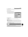
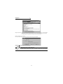
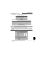
(3) Running the installation program
1) The [Run] dialog box appears.
2) Type "D:\SETUP" (use half-size letters) in [Open] and click the [OK] button or press the
key. (When the
CD-ROM drive is drive D)
3) After that, perform operation in accordance with the setup guide (screen).
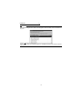
(4) When file copying is over, the following screen appears. Always enter the user and company names and click
the [OK] button.
Installation is not completed unless the user and company names are entered.
(5) When installation is finished, the "Uninstall", "VFD Setup S/W" and "VFD Setup S/W Help" icons are registered
and the following screen appears.
OVERVIEW
1
5
MEMO
6
2
FUNCTIONS
This chapter describes the "functions" for use of this product.
Always read the instructions before using this software.
2.1
2.2
2.3
2.4
2.5
2.6
2.7
2.8
2.9
Starting the VFD Setup Software...................................8
Settings..........................................................................9
Parameter ....................................................................14
Monitor.........................................................................20
Diagnosis .....................................................................33
Test Running................................................................35
Advanced Function ......................................................37
Saving, Reading and Printing the Files........................42
Help .............................................................................43
1
2
3
4
7
Starting the VFD Setup Software
2.1 Starting the VFD Setup Software
Start the VFD Setup Software with "INVSUPE.EXE".
CAUTION
Start only one VFD setup software program.
<Primary screen>
※
REMARKS
" Next time no disp.": When you check , the above screen will not appear from the next time the software is run.
To display it again, check the check box "Display the initial screen", see section "2.2.3 Environmental Setting" (refer to page 13).
<Initial screen>
8
Settings
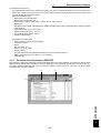
2.2 Settings
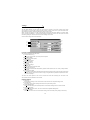
When you press the [OK] button on the initial screen, the following screen appears:
1)
2)
3)
4)
5)
6)
7)
8)
(1) Menu list
This software has the following functions:
File
(Alt+F)
Settings
(Alt+S)
Pull-Down Menu
Function/Operation
Ctrl+O
Open
Close
Save
Ctrl+S
Save As Ctrl+A
Print
Ctrl+P
Exit
System Settings
Communication Settings
Opens a file.
Closes the screen.
Saves data.
Save data with a new name.
Selects printing.
Performs exiting procedure.
Sets the model, capacity (size) and option type. (Stations 00 to 31)
Sets serial communication information.
Sets the directory where data will be stored and sets re-display of the initial
screen.
Shows and sets the parameter list.
Shows and sets the related parameters function-by-function.
You can register or delete a total of 32 parameters out of all parameters to
or from two different user groups.
You can set the parameters required for starting up the inverter without
being aware of parameter numbers.
Shows four pieces of data (up to four stations) in terms of values.
Shows four pieces of data (up to four stations) in terms of meter deflections.
Shows four pieces of data (up to four stations) in terms of waveforms.
Shows the alarm history of all inverter stations connected.
Analyzes various types of data.
Shows various data of all stations connected in real time in terms of values.
Examine the estimated cause of the alarm in accordance with the alarm
display.
Gives the operation command from the personal computer to actually test
run the inverter.
Performs auto tuning in accordance with the motor connected to the
inverter.
Measures the response frequency characteristic of speed relative to the
motor torque of the machine.
Overlapping Windows.
Windows are side-by-side.
Various help functions (parameter explanations, function explanations, etc.)
Version information (copyright, version information, user and company
names, etc.)
Environmental Settings
All list Format
Functional List Format
Parameter
(Alt+P)
Individual list Format
Basic Settings
Monitor
(Alt+M)
Diagnosis
(Alt+N)
Test Running
(Alt+T)
Advanced function
(Alt+V)
Window
(Alt+W)
Help
(Alt+H)
Data Display
Meter Display
Oscilloscopes
Alarm History
Trace Oscilloscopes
VFD Status
Diagnosis
Test Running
Auto Tuning
Machine Analyzer
Cascade Display
Tile Display
Contents
About VFD Setup S/W
9
2
FUNCTIONS
Menu
Settings
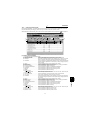
(2) Description of various buttons and indications
1) Node
The station number selected is displayed.
2) [EXT] (Alt+X), [PU] (Alt+U) and [LNK] (Alt+L) buttons
You can choose the inverter operation mode for online operation.
⋅ [EXT] button: External operation mode
⋅ [PU] button: PU operation mode
⋅ [LNK] button: Computer link operation mode
3) The operation mode and error codes appear. (Refer to page 46 for the error codes.)
Operation mode indications
⋅ EXT............................ External operation mode
⋅ PU.............................. PU operation mode
⋅ EXT JOG ................... External jog mode
⋅ PU JOG ..................... PU jog mode
⋅ LNK............................ Computer link mode
⋅ PU EXT...................... PU-external combined mode
⋅ TIME .......................... Time scheduled operation
⋅ SP .............................. Special mode
⋅ No Node..................... Time-out occurred in the online mode
In any other case, the error number at NAK error occurrence appears.
⋅ When an alarm occurs, the operation mode and error codes are displayed in red.
⋅ To display a warning, the operation mode and warning appear.
4) [ONLINE/OFFLINE] (Alt+O) button
⋅ [ONLINE] (online) button: Online operation mode
⋅ [OFFLINE] (offline) button: Offline operation mode
Click the corresponding button to select the online or offline mode.
5) System settings
You can set the environment of the inverters of stations 00 to 31.
Set the model, capacity and options for these inverters.
6) [New] button (Alt+E)
Used to make new system settings.
7) [System Read] button (Alt+Y)
Used to batch-read all inverters in the system with which the personal computer communicates.
8) [Confirmed] button (Alt+I)
You can register the data specified in the system settings. Always confirm the entry with the [Confirmed] button when you have changed the setting of the system configuration manually.
10
Settings
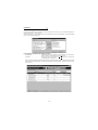
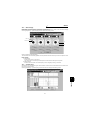
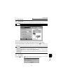
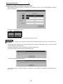
2.2.1
System Settings
This screen appears when you start this software and press the [OK] button on the initial screen.
On this screen, set the station numbers, models, capacities and plug-in options of the inverters connected. Inverters
can be set to stations 0 to 31.
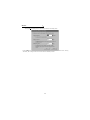
(1) Station selection (Ctrl+N)
Click the required station number. That line is then chosen.
(2) Selection of model, capacity and options
When you double-click the selected line, the "VFD
Structure" panel (as shown on the right) appears. Set
the model, capacity and options and press the [OK]
button to complete the settings. Using the same procedure, set all inverter stations which connected.
(3) [Confirmed] button (Alt+I)
After setting all stations, pressing the Confirmed button completes the system settings.
(4) [New] button (Alt+E)
Press the New button to initialize (clear) the system settings/communication settings being edited.
(5) [System Read] button (Alt+Y)
Before pressing the [System Read] button, press the [ONLINE/OFFLINE] button to change the mode indication
to [ONLINE] and select the online operation mode. In the online operation mode, the personal computer is
switched to the inverter communication status and clicking the [System Read] button reads the models, capacities and options of all stations (stations 0 to 31) and displays the stations connected (with which the personal
computer can communicate).
After reading, the settings are registered automatically.
When the system settings have not yet been made, the read stations are displayed. When the system settings
have already been registered, check is performed. If the check result is different from the read data, select
whether different points are displayed and changed or not.
11
2
FUNCTIONS
CAUTION
1. When the [Cancel] button is clicked during [System Read], the system setting made until then is verified.
2. When the [System Read] button is pressed, the 100V or 200V class of the FR-E500 series is displayed
as the FR-E520-NA, the 400V class as the FR-E540-NA, and the 100V class of the FR-S500 series as
the 200V class.
When the model differs from that, change the model manually.
Settings
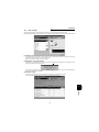
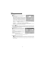
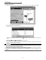
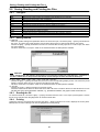
2.2.2
Communication Settings
The VFD Setup Software uses the serial port of the personal computer to control the inverters through serial
communication. Its communication settings must be the same as those of the inverter. (The initial values of the
setup software have been matched with the factory settings of the inverter.)
When you start this software, the initial screen appears. Pressing the [OK] button displays the system setting
screen. Choosing the [Settings] → [Communication settings] command on the menu bar. The screen then shows
the following dialog box, where various communication settings can be made.
Communication settings will be described below:
5)
1)
2)
6)
3)
4)
7)
8)
(1) Screen explanations
The values in parentheses are initial values.
1) Communication Port (1)
Choose the communication port of the personal computer.
2) Baud Rate (19200)
Set the communication speed.
3) Data Length (8)
Set the data bit length.
4) Parity Check (Even)
Specify the parity bit.
5) Stop Bit (2)
Set the stop bit length.
6) Delimiter (CR)
Specify the delimiter at the data trailer.
7) Interrogate Time [sec] (1)
Set the interval at which data transmission (operation mode indication and error check) is always made to
the inverter.
8) Time Out [msec] (1000)
Set the time from when data is transferred from the personal computer to the inverter until when the personal
computer receives a reply from the inverter. If a reply is not given after the preset time has passed, the "timeout" error is displayed.
The above set values depend on the inverter connected. Set them after confirming the set values of the
communication function parameters of the inverter.
(2) Button settings
1) [OK] button
Recognizes the settings on the communication screen and returns to the system setting screen.
2) [Cancel] button
Cancels the communication settings and returns to the system setting screen.
3) [Reflect Default] button
Used to omit the setting of the values specified in communication settings from the next time onward.
4) [Default Read] button
Used to read the default values. The value is as set with the [Reflect Default] button.
5) [Initial Value] button
This button is used to return the communication setting to the initial value (factory setting of the inverter).
12
Settings
(3) Inverter communication settings
The values set for communication depend on the inverter and connection method.
Inverter
FR-A520(-NA)
FR-A520L
FR-A540(-NA) (-EC) (-CH)
FR-A540L (-NA) (-EC)
FR-F520
FR-F540 (-EC) (-CH)
FR-V520
FR-V540
FR-E520 (-NA)
FR-E520S (-EC) (-CH)
FR-E510W (-NA)
FR-E540 (-NA) (-EC) (-CH)
FR-S520-R
FR-S520S-R
FR-S520S-ECR (-CHR)
FR-S510W-R
FR-S540-R (-NAR) (-ECR) (-CHR)
Connection Method
Operation mode
PU connector
(RS-485 connector)
or
FR-A5NR
⋅ When PU connector
(RS-485 connector) is
connected PU mode
⋅ When FR-A5NR is
connected LINK
mode
PU connector
(RS-485 connector)
PU mode
RS-485 connector
LINK mode
Setting Range
[Node]
[Baud rate]
[Stop bit]
[Data length]
[Parity bit]
[Delimiter]
Station 0 to 31
4800, 9600, 19200 bps
1 bit, 2 bits
7 bits, 8 bits
None, odd, even
None, CR, CR+LF
CAUTION
When making communication with the inverters, set a value other than 0 in Pr. 122 "communication
check time interval" on the inverter's operation panel. For the FR-A5NR, set any value other than 0 in Pr.
336 "communication check time interval", and for the FR-S500 series, set any value other than 0 in the
communication parameter n6 (336) "communication check time interval".
(Refer to the inverter instruction manual for the setting method.)
(4) Interrogate time
Set the interval at which data is always sent or received to or from the inverter.
It must be set to at least 2 seconds shorter than the communication check time interval setting of the inverter. If
its setting is longer than the communication check time interval setting, the inverter will come to an alarm stop.
CAUTION
The setting of short interrogate time may slow down the response of the menus and buttons on each
window depending on the operating model and communication speed.
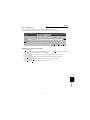
2.2.3
Environmental Setting
You can specify the data directory (place where data is saved) and default system file.
1)
2)
5)
3)
4)
1) Data Directory..................................... You can change the directory where data will be saved.
2) Display the initial screen ..................... Checking the check box displays the initial screen.
3) Default Sys File .................................. Shows the system file (*.MEL) which is automatically set when starting of the software.
There is no default registered.
4) Browse................................................ Default system file browsing button.
Shows the file selection common dialog and displays the chosen file
name in the default system file text box.
5) When the parameter is read it is
distinguished automatical ................... Turn on the check box to hide the parameters read-disabled for
parameter batch-read or batch-verify from the error panel. (Refer to
page 16)
13
FUNCTIONS
2
(1) Screen explanations
Parameter
2.3 Parameter
When system settings are complete, you can choose menu parameters.
Choose the [Parameter] → [All List Format], [Functional List Format], [Individual List Format] or [Basic Settings]
command in the menu to select the corresponding format, and set parameters. Any parameter setting is changed by
first entering new data in the Updated column and then pressing the [Write] or [Blk Write] button. The new data is
then displayed in the Current setting column, which shows the current settings of the inverter.
2.3.1
All List Format
By choosing the [Parameter] → [All List Format] command in the menu, all parameters of the inverter are displayed
as a list. When changing any parameter setting, enter a new value in the required parameter column and press the
key to register it.
1)
2)
3)
4)
5)
6)
7)
8)
9)
10)
11)
12)
13)
14)
(1) Buttons and indications common to various parameter setting screens
1) Node (Ctrl+N) ............................. Indicates the inverter station number to be set (only the station numbers
registered in the system settings may be selected.)
2) Inverter operation mode ............. Used to choose/display the operation mode of the selected inverter station
number.
3) Online/offline (Alt+O) .................. To read/write the parameter values of the inverter, select the online operation mode.
4) Setting Range............................. Indicates the setting range of the selected parameter.
5) Pr Jmp (Alt+J),
updated Val (Alt+E)..................... Shows the number and new value of the selected parameter. Values may
be entered directly into these columns.
6) Detail Information (Alt+D,F1) ...... Shows the function explanation of the selected parameter.
14
Parameter
7) Change List (Alt+G) .................... Lists the parameters with the present set values which have been changed
from the initial values.
8) Parameter initialization (Alt+R) ... Initializes the parameters of the inverter. (The communication parameters
are not initialized.)
Choose the clearing method from among "Parameter Clear", "All Clear"
and "User Clear" on the following panel and click the [OK] button to execute clear.
CAUTION
Changing the Pr. 21 setting automatically switches the minimum setting increments of the acceleration/
deceleration time-related parameters (Pr. 7, Pr. 8, Pr. 16, Pr. 45, Pr. 46, Pr. 110, Pr. 111, Pr. 264, Pr.265).
(Increments are 0.1s when Pr. 21=0, 0.01s when Pr. 21=1)
The acceleration deceleration time-related parameters differ according to the inverter. Refer to the
inverter manual for details.
15
2
FUNCTONS
9) Copy (Alt+Y) .................................. ⋅ System setting file (*.MEL)
Used to copy the parameter list as
a file to the inverter. Choose the
system setting file (*.MEL) and
click the [OK] button to display the
panel shown on the right. Making
selections at "Copy" and "Node"
and clicking the [OK] button reads
the parameter settings and sets
them to the Updated column.
Therefore, by performing block
write after that, they are copied to the inverter. (Parameter copy cannot be
made between different models.)
⋅Parameter setting file (*.PRM)
Choosing the parameter setting file (*.PRM) displays the present settings
in the Updated value field of the screen. (When only the present settings
are saved)
When there are both the present settings and updated values, display the
parameter copy panel (shown above) and select the values to be copied.
10) Blk Read (Alt+B) ....................... Reads all parameters of the selected inverter station number.
11) Read (Alt+A) ............................. Reads the data of the parameter numbers selected on the screen.
12) Blk Check (Alt+C) ..................... Batch-checks the parameters of the inverter against those of the personal
computer.
13) Blk write (Alt+K) ........................ Writes new parameter values to the inverter.
(When there are no values in the Updated value field, the screen for
selecting whether the present settings will be written or not appears. Perform operation following the screen prompts.)
14) Write (Alt+I) ............................... Writes the data of the parameter numbers selected on the screen.
Parameter
CAUTION
If an error occurred during "block read", "block check" or "block write", the parameter list appears on the
panel. Double-clicking the error number in the displayed list shows the details of the error definition on
the panel.
[When the parameter is read it is distinguished automatically]
Turning on this check box automatically judges the read-disabled parameters and hide them from the
read error panel.
16
Parameter
2.3.2
Functional List Format
By choosing the [Parameter] → [Functional List Format] command in the menu, the parameters are displayed as a function list.
For parameter setting and changing, values may only be written in the online operation mode.
When changing any parameter setting, enter a new value in the required parameter column and press the
key to register it.
14)
15)
2)
16)
3) 4)
13)
5)
6)
1)
7)
8)
9)
10)
11)
12)
(1) Various panel indications
•
1)
2)
3)
17
2
FUNCTONS
FR-A500(L)/F500(L)/E500/S500 series
Terminal allocation...................... Lists the parameters concerned with the control circuit terminals.
Magnetic flux vector.................... Lists only the parameters for magnetic flux vector control.
Intelligent .................................... Shows the parameters related to the intelligent mode in which the inverter
performs operation after setting appropriate parameters automatically.
4) Calibration .................................. Lists the parameters related to the calibration of the FM and AM terminals
and the bias/gain adjustments of the frequency setting voltage (frequency
setting current).
5) Option ......................................... Lists the parameters of the values related to the options.
6) Special running........................... Lists the parameters such as the functions used by making pre-selection.
7) Motor torque ............................... Lists the parameters related to motor torque.
8) Frequency settings ..................... Lists the parameters related to frequency.
9) Acceleration/deceleration ........... Lists the parameters related to acceleration/deceleration.
10) Protection.................................. Lists the parameters related to the protective functions.
11) Monitor ...................................... Lists the parameters related to the monitoring function.
12) Brake......................................... Lists the parameters related to braking.
13) Pr Jmp (Alt+J),
Updated Val (Alt+E) .................. Show the selected parameter number and its new value. Values may be
entered directly into these columns.
• FR-V500 series
1) Terminal allocation...................... Lists the parameters concerned with the control circuit terminals.
2) V/F control .................................. Lists only the parameters used to exercise V/F control.
4) Calibration .................................. Lists the parameters related to the calibration of the DA1 and DA2 terminals and the bias/gain adjustment of the speed setting voltage (speed setting current).
5) Option ......................................... Lists the parameters of the values related to the options.
6) Special running........................... Lists the parameters such as the functions used by making pre-selection.
7) Motor .......................................... Lists the parameters related to the motor.
8) Speed setting.............................. Lists the parameters related to the speed.
9) Acceleration/deceleration ........... Lists the parameters related to acceleration/deceleration.
10) Protection.................................. Lists the parameters related to the protective functions.
11) Monitor ...................................... Lists the parameters related to the monitoring function.
12) Brake......................................... Lists the parameters related to braking.
13) Pr Jmp (Alt+J),
Updated Val (Alt+E) .................. Show the selected parameter number and its new value. Values may be
entered directly into these columns.
14) Speed control............................ Lists the parameters related to speed control.
15) Torque control ........................... Lists the parameters related to torque control.
16) Position control ......................... Lists the parameters related to position control.
Parameter
2.3.3
Individual List Format
By choosing the [Parameter] → [Individual List Format] command in the menu, you can select two different user
groups ("User Group 1", "User Group 2").
To these user groups, you can register a total of 32 parameters from among all parameters. Click the [Edit Reg.]
button. The following panel appears.
(1) Description of individual list editing operation
1) Registration ................................. Choose the items to be registered in the "Parameter List" and press the
[Add>>>] button to register them to the "Individual List".
2) Deletion ....................................... Choose the items to be deleted in the "Individual List" and press the
[<<<Delete] button to delete them.
After choosing the parameters, pressing the [OK] button completes the user setting and displays the individually
selected list in the following panel. To save the individual list, choose the [File] → [Save] command from the
menu to save it.
18
Parameter
2.3.4
Basic Settings
Choosing the [Parameter] → [Basic Settings] command in the menu displays the following screen.
By entering data into the items shown on the screen, you can set the parameters without being aware of the parameter numbers.
(1) Setting of each specification
Set the specification of each item in the Specification column. When the [Click] button is provided, clicking it displays choices. Make selection and click the [OK] button.
60Hz is the maximum setting for operation speed.
(2) Registration of the specifications
After entering the specifications of all items, press the [Confirmed] button to register them. Pressing the [Confirmed] button displays the following panel.
By pressing the [OK] button, the parameters are set automatically and the new values of the parameters that
may be set automatically are displayed.
(3) Parameter setting
When the automatic settings of the parameters are registered, the following panel appears.
To write the new parameter values to the inverter, press the [Blk Write] button.
FUNCTONS
2
19
Monitor
2.4 Monitor
Choosing the [Monitor] - [Data Display], [Meter Display], [Oscilloscopes], [Alarm History] or [Trace Oscilloscopes]
command in the menu allows you to select the corresponding monitor item.
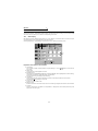
2.4.1
Data Display
Data Display shows four different signals (those of up to four stations) as numerical values in real time. The input
and output statuses of the control terminals can also be monitored.
Choosing the [Monitor] → [Data Display] command from the menu displays the following screen:
1)
2)
5)
6)
7)
4)
3)
Explanation of the buttons and indications
1) Node setting
You can enter the station number specified in "System Settings" or use the [ / ] button to choose the station number.
2) Display items
Choose the items to be displayed in the menu.
3) Start/Stop (Alt+A)
After pressing the [ONLINE/OFFLINE] button to display [ONLINE], click the [Start] button to start monitoring.
(The function of this button toggles depending upon the mode.)
Click this button during monitoring to stop monitoring.
4) Hold (Alt+D)
Clicking the [Hold] button holds the data being monitored. In this state, the data can also be saved.
Click this button during holding to cancel hold.
5) Present value
Shows the real-time monitor value.
6) Maximum value
Shows the maximum value of the monitor value. Once monitoring is stopped, the maximum value is cleared.
7) I/O status
When you have chosen "Input Status" or "Output Status" in "Display Item", the I/O status (ON or OFF) is displayed. (ON: red, OFF: gray)
20
Monitor
2.4.2
Meter Display
Meter Display shows four different signals (those of up to four stations) as meters in real time. Meter Display
handles show only data which can be indicated by meter deflections.
Choosing the [Monitor] → [Meter Display] command shows the following screen:
Max Val.
Present Val.
1)
2)
Perform operation as with Data Display.
The meter scales are automatically adjusted. After the parameters are batch-read, they are set to the optimum values.
Panel display
1) Meter display
Shows monitor values on the meters.
The present value is indicated by the black pointer and the maximum value by the red pointer.
2) Meter full-scale
Shows the full-scale value of the meter display. It can be changed by entering a new value.
2.4.3
Oscilloscopes
Oscilloscopes show four different signals, which had been received from the inverter beforehand, as waveforms on
the personal computer screen.
Choosing the [Monitor] → [Oscilloscopes] command from the menu displays the following screen:
FUNCTIONS
2
21
Monitor
[Operating procedure]
1) Setting (Alt+E)
Pressing the [Settings] button shows the "Measurement Conditions" panel.
a. Choose the station number and measurement item.
b. Trigger signal setting
Choose the outside, inside or alarm trigger. For "Outside
Trigger", pressing the [Measurement Start] button starts
measurement. For "Inside Trigger", since the signal from the
inverter is used as a trigger signal, set the station number
measurement signal, timing, trigger terminal and conditions.
For "Alarm Trigger", the alarm occurrence signal of the
inverter is used as a trigger signal. In this case, the trigger
settings valid are the station number and timing only.
[Timing] ...................... Choose the displayed data from among "Before", "During" and "After" the trigger
signal.
[Sampling Time] ......... Set the interval of importing data. (100 to 60000msec)
[Conditions] ................ Choose the "Rise" or "Down" timing when the trigger is activated.
c. After setting the measurement conditions, press the [OK] button. The screen returns to Oscilloscopes
and the station numbers and measurement items set appear.
2) Measurement start (Alt+A)
Press the [ONLINE] button. For "Inside Trigger", press the [Measurement Start] button to start the importing
of data. On a trigger condition match, waveforms are displayed on the screen. For "Outside Trigger", pressing the [Measurement Start] button starts the importing of data endlessly. After completion or (suspension),
press the [Play Back] button to display the data.
3) Scale Change (Alt+C)
To change the vertical and horizontal axis scales of the displayed waveforms, press the [Scale Change] button to display the "Scale Change" panel, on which the scales are to
be changed.
The full-scale values on the vertical axes and time axes
(horizontal axes) of the displayed waveforms of the four
channels (four stations) can be changed.
Specify the sampling count as the unit for the time axis (horizontal axis).
(Reference) Time converting method
: [sampling count] × [sampling interval]
+ [personal computer processing time] + [data importing time]
4) Play Back (Alt+B)
You can play back the measured oscilloscope data.
a. By pressing the [Play Back] button after the end of measurement, the oscilloscope data can be played
back. When the waveforms are being displayed, the screen is blanked once and the waveforms are then
played back.
b. You can play back saved oscilloscope data. By choosing [File] → [Open] to read the data, the waveforms
appear (are loaded).
22
Monitor
2.4.4
Alarm History
Alarm History displays the history of eight past alarms of all inverter stations connected.
Choosing the [Monitor] → [Alarm History] command from the menu displays the following screen.
2)
3)
5)
4)
1)
Explanation of the buttons and indications
1) Block Read (Alt+B)
Press the [ONLINE/OFFLINE] button to show [ONLINE] and then click the [Block Read] button to display the
alarm history of all stations specified in the system settings.
2) Alarm History
Lists the station numbers specified in the system settings and their history of eight past alarms.
3) Alarm Explanation
Clicking the alarm display column in the alarm history list shows the explanation of that alarm.
4) Alarm Clear (Alt+C)
Clicking the [Alarm Clear] button clears the alarm history of the chosen station inverter.
5) VFD Reset (Alt+R)
Clicking the [VFD Reset] button resets the chosen station inverter.
FUNCTIONS
2
23
Monitor
2.4.5
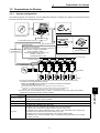
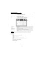
Trace Oscilloscopes (for FR-V500 series only)
The FR-V500 series allows you to trace various data by setting Pr. 520 to Pr. 536 and Pr. 538.
Using the trace function of the setup software, you can set the parameters on the trace function setting screen and
analyze the traced data. The trace function is available for the FR-V500 series only.
When using the trace function, the trace option unit T-TRC50 need to be fitted to the inverter. Install the trace option
unit T-TRC50 in Slot 1 of the inverter. If you install it in Slot 2 or 3, operation is not performed. The traced data are
stored in the memory of the trace option unit T-TRC50.
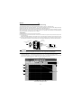
<Installation>
(1) Make sure that the input power of the inverter is OFF.
(2) Insert the option unit connector into the connector of the inverter securely. At this time, also insert the option fixing holes securely.
Refer to the following diagram for the position of Slot 1. Push the option unit securely into the option fixing hook.
(3) Fix the two left and right places of the option unit to the inverter securely with the accessory mounting screws. If
the screw holes do not line-up, the connector may not have been inserted securely. Check for insecure insertion.
Inverter
(without cover)
Trace option unit
Accessory screw
(2 pcs.)
Slot 1
Inverter side connector
Slot 2
Option fixing hook
Slot 3
Option side
connector
The slots 1, 2, and 3 are provided
with an option fixing hook.
CAUTION
1. You cannot use more than one same option units.
2. Option error (E.OP1) is displayed if the inverter does not recognize the mounted option.
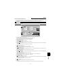
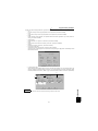
(1) Trace function oscilloscope screen
Choosing the [Monitor] → [Trace Oscilloscopes] command in the menu displays the following screen.
To use the trace function, you need to make trace function setting. Click the [Settings] button 14 to make trace
function setting. (Refer to page 27 for details of the trace function setting screen.)
1)
12) 15)
13)
11)
14)
10)
2)
9)
3)
7)
5)
8)
4)
6)
Trace function oscilloscope screen
24
Monitor
•Explanation of the buttons and indications
1) Channel setting indication
Shows a data name according of the setting of each channel. The indication is blanked when no data is set.
2) Screen split selection
You can choose any of one to four way splits. (Initial setting: One way split)
3) Channel indication
Clicking the channel of the data you want to display shows the data assigned to the clicked channel.
4) Terminal signal indication
Clicking [ ] displays a list of terminal signals to enable setting. Unset signal names are blanked.
Up to four terminal signals can be displayed simultaneously.
The input/output terminal signals can be displayed only when the input/output terminal signal data are
included in the CH1 to CH10 data.
Input terminal signals
STF, STR, DI1, DI2, DI3, DI4, OH, RES
Output terminal signals
DO1, DO2, DO3, ABC
5) CH signal screen/Terminal signal screen switchover
Clicking here alternates between the channel (CH) indication (3) and terminal signal indication (4).
6) Scroll
Clicking here shifts the whole screen left to right.
7) Scale adjustment
Click [ ]/[ ] to adjust the scale. The adjustable range is 50% to 400%. (Initial setting: 100%)
8) Data indication
Clicking [ ] and choosing the channel from the list displays on the screen the data value of the selected
channel at the point of the cursor A.
9) TA/TB
Clicking [ ]/[ ] moves the cursor to the left/right. The time indication of the cursor A on the right hand side
of [TA] also varies with the movement of the cursor A. This also applies to the operation of the cursor B.
10) Horizontal axis time unit
Clicking [ ]/[ ] changes the time unit of the horizontal axis. The changing range is 10ms to 500s. (Initial
setting: 20ms)
11) Read Data
Clicking [Read Data] starts data read. At the same time, the following screen also appears. Clicking "Cancel" stops data read and returns to the trace function oscilloscope screen.
12) Start Trace/Stop Trace
Clicking [Start Trace]/[Stop Trace] starts/stops a trace. (At this time, write "1" in Pr. 538 "trace start/stop
selection" for a start or "0" for a stop.)
13) Trace status indication
Shows the trace status. The trace status is monitored at intervals of 500ms.
Indication
Stop, waiting for pre-trigger, waiting for trigger,
during trace, trace completed
2
FUNCTIONS
14) Setting
Clicking [Setting] displays the trace function setting screen.
25
Monitor
15) Reference Data
Clicking [Reference Data] shows the data display reference value setting screen.
Clicking [ ]/[ ] varies the reference value setting. Clicking [OK] changes the data reference value. Clicking
"Cancel" stops the setting and returns to the trace function oscilloscope screen.
26
Monitor
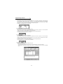
(2) Trace function setting screen
By changing the set values on the trace function setting screen and writing them to the parameters, you can
change the parameter settings of the inverter. (Refer to page 28 for details of the parameters.)
CAUTION
The trace function setting screen is used to only set the parameter values and not to write them. Use the
parameter check screen to write them. Click [Parameter check]. (Refer to page 32 for details of the
parameter check screen.)
1)
2)
3)
6)
4)
8)
5)
9)
7)
10)
27
2
FUNCTIONS
Trace function setting screen
1) Function setting [Pr. 520 to Pr. 529]
Select the data of CH1 to CH10. The selected data are displayed.
You can assign one piece of data to two or more channels.
Selecting the data changes the Pr. 520 to Pr. 529 values.
2) Sample Time [Pr. 530]
Vary the sampling period. (1 = 444s)
Varying the sampling period changes the Pr. 530 value.
3) Sample Mode [Pr. 531]
Set the number of samplings made at one time. Increasing the sampling count limits the number of data that
can be traced.
Changing the sampling mode changes the Pr. 531 value.
4) Trigger Signal 1 [Pr. 532]
A specific signal times the start and end of a trace.
Changing the trigger signal choice 1 changes the Pr. 532 value.
5) Trigger Signal 2 [Pr. 533]
When you have selected "Error (trigger signal choice 2)" in the trigger signal choice 1, select the error that
will output a trigger signal.
Changing the trigger signal choice 2 changes the Pr. 533 value.
6) Trigger Level [Pr. 534]
A trigger is enabled when the value of the data set in the trigger signal choice 1 reaches the set trigger level
on the trigger condition.
Changing the trigger level changes the Pr. 534 value.
7) Trigger conditions [Pr. 535]
Select whether a trigger will be enabled on the "leading edge" or on the "trailing edge".
Changing the trigger condition changes the Pr. 535 value.
8) Pre-trigger [Pr. 536]
Used to trace the data before trigger.
Specify the percentage of the trigger point on the assumption that the recording starting point is 0% and the
recording end point is 100%.
Changing the pre-trigger changes the Pr. 536 value.
9) View Parameter
Clicking [View Parameter] shifts to the parameter check screen.
10) Cancel
Clicking [Cancel] cancels function changing and returns to the trace function oscilloscope screen.
Monitor
(3) Parameter list
Parameter
Name
Setting Range
52
PU/DU main display data
selection
190
191
192
DO1 terminal function selection
DO2 terminal function selection
DO3 terminal function selection
195
ABC terminal function selection
520
521
522
523
524
525
526
527
528
529
530
531
532
Trace data CH1
Trace data CH2
Trace data CH3
Trace data CH4
Trace data CH5
Trace data CH6
Trace data CH7
Trace data CH8
Trace data CH9
Trace data CH10
Sampling period
Sampling count selection
Trigger source selection 1
533
Trigger source selection 2
534
535
536
538
Trigger level
Trigger slope selection
Pre-trigger
Trace start/stop selection
Factory Setting
0, 5 to 12, 17 to 20, 23,
24, 32 to 35, 38, 100
(5 to 12 are invalid for FR-PU04V)
0 to 8, 10 to 16, 20, 25 to 27, 30 to
37, 39 to 44, 96 to 99,
100 to 108, 110 to 116, 120,
125 to 127, 130 to 137,
139 to 144, 196 to 199, 9999
1 to 12, 15 to 20, 23, 24,
32 to 36, 50 to 56, 9999
1 to 9998
1, 2, 3, 4
0 to 17, 22, 31 to 34, 9999
0 to 23, 25, 26, 29 to 40,
46 to 48, 51, 52, 9999
600% to 1400% (*)
0, 1
0 to 100%
0, 1
0
0
1
2
99
1 (speed)
2 (output current)
3 (output voltage)
4 (alarm display)
5 (set speed)
15 (input status (DI))
16 (output status (DO))
50 (U phase output current)
51 (V phase output current)
52 (W phase output current)
1
1
9999
9999
1000%
0
85%
0
REMARKS
1. *: In Pr. 534, set the trigger level value (-400% to 400%) plus 1000.
2. When Pr. 538 = "1", you cannot write any parameter values to Pr. 520 to Pr. 536.
3. You can write parameter values to Pr. 520 to Pr. 536 and Pr. 538 if Pr. 77 = "0".
(4) Parameter details
1. Trace status (Pr. 52, Pr. 190 to Pr. 192, Pr. 195)
The trace progress status, data output status and so on can be displayed on the DU/PU monitor and output to the
external output terminals.
⋅ Pr. 52 "PU/DU main display data selection"
When "38 (trace status)" is set in Pr. 52, the trace status is displayed on the FR-DU04-1/FR-PU04V.
Monitor Display
Trace Status
0
1
2
3
4
Stop
During pre-trigger
Waiting for trigger
During trace
Trace completed
REMARKS
• The trace status is displayed instead of the output voltage monitor of the DU/PU main monitor.
⋅ Pr. 190 to Pr. 192, Pr. 195 "output terminal function selection"
When you set "40 (positive logic) and 140 (negative logic)" (Y40 signal: trace status) in Pr. 190 to Pr. 192 and
Pr. 195, the trace status is output from the output terminals.
Y40 Signal
40
140
(positive logic) (negative logic)
OFF
ON
ON
OFF
Trace Status
Stop, trace completed, during data output, data output completed
During pre-trigger, waiting for trigger, during trace
28
Monitor
2. Function setting (Pr. 520 to Pr. 529)
⋅ Pr. 520 to Pr. 529 "trace data CH1 to CH10" (1 to 12, 15 to 20, 23, 24, 32 to 36, 50 to 56, 9999)
Set the data to be traced. You can set the data of CH1 to CH10.
Setting
Name
Setting
Name
Setting
Name
9999
1
2
3
4
5
6
7*
8
9
10
No trace data CH setting
Speed
Output current value
Output voltage value
Alarm display
Set speed
Output frequency
Motor torque
DC bus voltage
Regenerative brake duty
Thermal load factor
11
12
15
16
17*
18*
19
20
23
24
32*
Output current peak value
Converter voltage peak value
Input status (DI)
Output status (DO)
Load meter
Motor exciting current
Position pulse
Energization time
Operation time
Motor load factor
Torque command
33*
34*
35*
36*
50
51
52
53*
54
55
56
Torque current command
Motor output
Feedback pulse
Torque monitor
U phase output current
V phase output current
W phase output current
Torque current
U phase voltage command value
V phase voltage command value
W phase voltage command value
CAUTION
*: Data that are made invalid under V/F control. If they are traced, correct values will not be displayed.
REMARKS
The data to be traced can be assigned to two or more channels.
3. Sampling setting (Pr.530, Pr.531)
⋅ Pr.530 "Sampling period" (1 to 9998)
Change the sampling period.
Sampling period = T
× Pr.530
T=444 µ s
⋅ Pr.531 "Sampling count selection" (1 to 4)
Set the number of samplings made at one time. Increasing the sampling count limits the number of data that
can be traced.
Pr. 531 Setting
Sampling Count
Number of Usable Channels
1
2
3
4
360
720
1080
1440
10
4
2
1
CAUTION
1. Set "9999" (no trace data CH setting) in Pr. 520 to Pr. 529 of any unused channel.
2. When Pr. 531 = "2 to 4", the operating channels have the priorities of CH1, CH2 ... and the channel that
has exceeded the number of usable channels does not operate.
4. Trigger source setting (Pr.532, Pr.533)
⋅ Pr.532 "Trigger source selection 1" (0 to 17, 22, 31 to 34, 9999)
A specific signal can be used to time the start and end of a trace.
When Pr. 532 = "1 to 10", set the trigger level in Pr. 534 and Pr. 535.
Trigger Source
Setting
Trigger Source
9999
0
1
2
3
4
5
6
7
8
9
10
Error (all errors)
Error (any error can be selected using Pr. 533)
Trace data CH1 setting data
Trace data CH2 setting data
Trace data CH3 setting data
Trace data CH4 setting data
Trace data CH5 setting data
Trace data CH6 setting data
Trace data CH7 setting data
Trace data CH8 setting data
Trace data CH9 setting data
Trace data CH10 setting data
11
12
13
14
15
16
17
22
31
32
33
34
STF
STR
RES
DI1
DI2
DI3
DI4
OH
ABC
DO1
DO2
DO3
CAUTION
1. A trace start trigger is made valid when Pr. 538 = "1". To trace data again after a trace start trigger, set
"1" in Pr. 538.
2. When using the input/output terminal signal as a trigger source, set any of "11 to 17, 22, 31 to 34" in Pr.
532. Do not set the trace data CH1 to 10 (Pr. 520 to Pr. 529 = "15, 16"), to which the input status/output
status has been set, as a trigger source.
29
2
FUNCTIONS
Setting
Monitor
⋅ Pr.533 "Trigger source selection 2" (0 to 23, 25, 26, 29 to 40, 46 to 48, 51, 52, 9999)
Pr.532 "Trigger source selection 1" = When you selected "0 (error)", choose the error that will output the trigger
signal.
Setting
Indication
Code
Setting
Indication
Code
9999
0
No error
Overcurrent shutoff during acceleration
Overcurrent shutoff during
constant speed
Overcurrent shutoff during deceleration
Regenerative overvoltage shutoff
during acceleration
Regenerative overvoltage shutoff
during constant speed
Regenerative overvoltage shutoff
during deceleration
Motor overload shutoff
Inverter overload shutoff
Momentary voltage
interruption protection
Undervoltage protection
Brake transistor alarm detection
Output side ground fault
overcurrent protection
External thermal operation
Stall prevention
Option alarm
Option slot 1 alarm
Option slot 2 alarm
Option slot 3 alarm
Parameter storage device alarm
Parameter unit disconnection
Retry count excess
E.0
E.OC1
21
22
CPU error
Fan fault
E.CPU
FN
E.OC2
23
Fin overheat
E.FIN
E.OC3
25
Excessive acceleration deviation detection
E.OSD
E.OV1
26
Open cable detection
E.ECR
E.OV2
29
Brake sequence error 1
E.MB1
E.OV3
30
Brake sequence error 2
E.MB2
E.THM
E.THT
31
32
Brake sequence error 3
Brake sequence error 4
E.MB3
E.MB4
E.IPF
33
Brake sequence error 5
E.MB5
E.UVT
E.BE
34
35
Brake sequence error 6
Brake sequence error 7
E.MB6
E.MB7
E.GF
36
24VDC power output short circuit
E.P24
E.OHT
E.OLT
E.OPT
E.OP1
E.OP2
E.OP3
E.PE
E.PUE
E.RET
37
38
39
40
46
47
48
51
52
Operation panel power supply short circuit
Lost output phase failure protection
P12 alarm
Encoder phase error
Error 1
Error 2
Error 3
Error 6
Error 7
E.CTE
E.LF
E.P12
E.EP
E.E1
E.E2
E.E3
E.E6
E.E7
1
2
3
4
5
6
7
8
9
10
11
12
13
14
15
16
17
18
19
20
5. Trigger level setting (Pr.534, Pr.535)
A trigger is enabled when the value of the data set in Pr. 532 "Trigger source selection 1" reaches the trigger level
set in Pr. 534 on the trigger condition set in Pr. 535.
This setting is made valid when Pr. 532 = "1 to 10".
REMARKS
Set the trigger level (Pr. 534, Pr. 535) when Pr. 532 = "1 to 10". However, the trigger level is made invalid when the channel
where "4: alarm display" is set to the trace data CH setting (Pr. 520 to Pr. 529) is used as a trigger source.
⋅ Pr.534 "Trigger level" (-400% to 400%)
Refer to the following table for calculation of the trigger level.
Trigger Data
Reference
Value
Speed
Pr.55
Output current value
Output voltage value
Alarm display
Set speed
Output frequency
Motor torque
Pr.56
400V/800V
1
Pr.55
120
Pr.866
DC bus voltage
500V/1000V
Regenerative brake duty
100%
Thermal load factor
100%
Output current peak value
Pr.56
Trigger Data
Converter voltage peak
value
Input status (DI)
Output status (DO)
Load meter
Motor exciting current
Position pulse
Energization time
Reference
Value
Trigger Data
Reference
Value
Inverter
capacity
--Feedback pulse
0×ffff/4
--Torque monitor
Pr.866
Pr.866
U phase output current Rated current
4096/rating V phase output current Rated current
0×ffff/4
W phase output current Rated current
0×ffff/4
Torque current
Rated current
U phase voltage
Operation time
0×ffff/4
400V/800V
command value
V phase voltage
400V/800V
Motor load factor
100%
command value
W phase voltage
400V/800V
Torque command
Rated current
command value
Torque current command Rated current
400V/800V
Motor output
CAUTION
When setting the trigger level on the setup software, set it within the range -400% to 400%. When directly
setting the parameter (Pr. 534) of the inverter, set the calculated trigger level plus 1000 (600% to 1400%).
30
Monitor
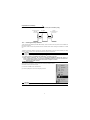
⋅ Pr.535 "Trigger condition"
Select whether a trigger will be enabled on the "leading edge" or on the "trailing edge".
Pr. 535 Setting
0
1
Function
Trigger is enabled on the leading edge.
Trigger is enabled on the trailing edge.
Time
Trigger point
Trigger point
Trigger data
Trigger data
Trigger level
(Pr.534)
Trigger level
(Pr.534)
Trailing edge
(Pr.535=1)
Leading edge
(Pr.535=0)
6. Pre-trigger (Pr.536)
⋅ Pr.536 "Pre-trigger" (0 to 100%)
Used to trace the data before a trigger.
Specify the percentage of the trigger point on the assumption that the recording starting point is 0% and the
recording end point is 100%.
<Example>
Pr.536 = "85%"
Trigger point
Pre-trigger
85%
15%
Recording length
Time
Trace record
CAUTION
If a trigger occurs during a pre-trigger, the trigger signal is not made valid. The trigger signal is made
valid after the pre-trigger time zone has ended.
7. Trace start, stop (Pr.538)
⋅ Pr.538 "Trace start/stop selection"
Select the start or stop of a trace.
On completion of a trace, Pr. 538 is automatically set to "0".
Pr. 538 Setting
0
1
Description
Trace stop/completion
Trace start
CAUTION
When "1" is set in Pr. 538, the previous trace data is deleted.
FUNCTIONS
2
31
Monitor
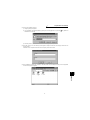
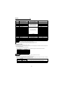
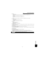
(5) Parameter check
1)
2)
4)
3)
Parameter check screen
1) Present setting
Parameter value currently stored in the inverter.
2) Updated value
New parameter value set using the trace function.
3) OK
Checking the parameter setting and clicking [OK] writes that value to the parameter.
Completion of write returns to the trace function oscilloscope screen.
4) NG
Clicking [NG] returns to the trace function setting screen without write to the parameter being performed.
32
Diagnosis
2.5 Diagnosis
2.5.1
VFD Status
Choosing the [Diagnosis] → [VFD Status] command in the menu displays the following screen.
CAUTION
This command can be chosen in the online mode only.
VFD Status: Displays the output current, output voltage, DC link V, Regenerative brake duty, THM factor, Power on
Time and Running Time data of all inverter stations specified in the system settings in real time. The
data can also be locked by pressing the [Hold] button (Alt+D). The values displayed can be switched
between absolute value indication and % indication (Alt+V).
CAUTION
The FR-E500 series or FR-S500 series displays only the output currents/output voltages.
2.5.2
Diagnosis
Choosing the [Diagnosis] → [Diagnosis] command from the menu displays the following screen:
CAUTION
This command can be chosen in the online mode only.
Alarm
Diagnosis (Alarm): Click the [Block Read] button (Alt+B) to batch-read the information of the inverters where alarms
have occurred. By clicking the corresponding item, its comment appears.
• Alarm Clear (Alt+C)
Clicking the [Alarm Clear] button clears the alarm history of the chosen station inverter.
• VFD Reset (Alt+R)
Clicking the [VFD Reset] button resets the chosen station inverter.
FUNCTIONS
2
33
Diagnosis
No Alarm
Diagnosis (No Alarm): Shows the diagnosis items. When you choose the corresponding item, the panel appears.
Enter data in accordance with the display. As a result, the estimated cause, etc. is shown.
For diagnosing the running status, the online mode must be selected.
[Alarm occurrence in online mode]
If an inverter alarm has occurred in the online mode, the following panel appears:
Clicking the [Yes] button shows the Diagnosis (Alarm) screen.
Clicking the [Help] button shows the alarm detail help.
CAUTION
The above alarm panel appears only once in the online mode.
Once you have closed the alarm panel, it will not appear even during alarm occurrence. By changing the
online mode to the offline, then to the online again, however, the panel will appear again if an alarm has
occurred.
34
Test Running
2.6 Test Running
2.6.1
Test Running
Choosing the [Test Running] → [Test Running] command from the menu displays the following screen.
CAUTION
This command can be chosen in the online mode only.
Operation procedure
1) Set the station number of the inverter to be run and the operation mode (PU or LNK (Link) operation).
2) Enter the running frequency (running speed for the FR-V500 series) and press the
key to confirm.
3) Click the [JOG FWD] (Shift+F5) or [JOG REV] (Shift+F6) button. The motor rotates while the button is being
pressed. The output frequency (speed for the FR-V500 series), output voltage and output current are monitored
on the screen.
CAUTION
1. If your inverter is the FR-E500 series, set any value other than "0" in Pr. 146 "frequency setting command selection".
2. When selecting [JOG REV (Shift+F6)] for the FR-S500 series, set "---" in Pr. 63 "STR terminal function
selection". Setting other than "---" does not enable [JOG REV (Shift+F6)].
3. The inverter stops if the F6 key is pressed and then released while the inverter is running with [JOG
FWD (shift+F5)].
Likewise, the inverter also stops if the F5 key is pressed and then released during running with [JOG
REV (shift+F6)].
Auto Tuning
2
Choosing the [Test Running] → [Auto Tuning] command from the menu enables auto tuning. You have to set the
auto tuning parameters in advance. If they have not been set, the following screen appears:
35
FUNCTIONS
2.6.2
Test Running
<Operation procedure>
1) Set the station number of the inverter to be run and the operation mode (PU or LNK (Link) operation).
2) Confirmation of the auto tuning parameters
Clicking the [Check] button (Alt+C) shows the parameters on the screen in a dialog box.
After entering all parameter set values, click the [Blk Write] button to write the new parameter values to the
inverter.
3) Click the [FWD] (Alt+D) or [REV] (Alt+R) button.
The LED block and monitor screen display the auto tuning status.
When Pr. 96 = "101", the motor is rotated. The motor stops on completion of auto tuning. If the auto tuning
has failed, follow the dialog box instructions.
CAUTION
1. In the offline mode, test running and auto tuning cannot be performed.
2. Before starting test running, check and if necessary adjust the parameters. Not doing so may cause
some machines to perform unexpected operation.
3. Provide safety backup devices such as emergency brakes to ensure that the machinery and equipment are not put in hazardous conditions if the inverters become faulty.
4. Auto tuning is not available for the FR-F500 series and FR-S500 series. (Can be displayed on the
screen.)
36
Advanced Function
2.7 Advanced Function
2.7.1
Machine analyzer (for FR-V500 series only)
Machine analyzer reads and analyzes the torque and speed data available when the inverter oscillates the motor at
random torque for about 0.5 to 4 seconds.
This allows measurement of the response frequency characteristic of speed relative to the motor torque of the
machine so that you can grasp the frequency at which the mechanical system has the resonance point.
CAUTION
1. The machine analyzer function is available for only the system that can perform PLG vector control
with the FR-V500 series.
2. The machine analyzer function is not performed in any of the following cases.
⋅ During inverter operation
⋅ When the second motor is selected (Pr. 450 ≠ "9999")
⋅ When the control mode is other than the PLG vector control mode (Pr. 800 ≠ "0 to 5")
(1) Machine analyzer screen
Choosing the [Advanced function] → [Machine analyzer] command in the menu displays the following screen.
Before starting machine analyzer operation, set the oscillation conditions and oscillation mode.
2)
3)
4)
1)
5)
6)
37
2
FUNCTIONS
Machine analyzer screen
•Various buttons, status indications
1) Waveform data
Frequency characteristic measurement results are displayed in the board chart (gain, phase).
2) Start
Used to start Machine analyzer.
3) Stml Condition
Set the oscillation conditions for Machine analyzer.
4) Stml Mode
Set the oscillation mode for Machine analyzer.
5) Resonance point, opposite resonance point cursors
Used to directly enter and specify the resonance point and opposite resonance point when they cannot be
detected automatically.
6) Y-axis Scale Optimization
Used to change the scale automatically so that the waveform is contained within the screen.
Advanced Function
(2) Machine analyzer setting
Make the following settings when using Machine analyzer.
1) Stml condition
⋅ "% of rated Torque".................................... Set the maximum oscillation torque for oscillating the motor
under a random torque command. (Setting range: 1 to 100%)
⋅ "Stroke"...................................................... Set the rotation range permitted for oscillation, beginning at the
motor position when Machine analyzer is started. If this range is
exceeded, Machine analyzer is stopped immediately, and the
motor is coasted in the vertical shaft mode or is coasted after
deceleration in the normal mode. (Setting range: ±1 to ±1000
revolutions)
REMARKS
• If a measurement result varies, accurate measurement may not have been made.
• Accurate measurement may not be made in a mechanical system whose oscillation torque is too small or whose friction is
large. In such a case, increase the oscillation torque and restart Machine analyzer.
• If the oscillation torque is too large relative to the load inertia moment, an overcurrent or similar alarm may occur. At that
time, reduce the oscillation torque and restart Machine analyzer.
• Starting oscillation switches to the torque control mode automatically, shifting a position. Before starting operation after
oscillation, therefore, always make a home position return.
2) Stml mode
⋅ "Normally Mode" ................ The inverter operates in the torque control mode, oscillating the motor randomly.
⋅ "Vertical Axis Mode"........... A servo lock is placed in the speed control mode, preventing a drop. Gain setting must have been made to ensure that stable servo lock operation will be
performed at that time.
REMARKS
In "vertical shaft mode"
⋅ The accuracy of 100Hz or less on the low frequency side may become low.
⋅ Too high setting of the position loop gain (Pr. 422) may lower the measurement accuracy.
CAUTION
When the machine is a vertical shaft, always perform this function in the "vertical shaft mode" since a
drop may occur.
38
Advanced Function
(3) Starting Machine analyzer operation
1) Checking the settings
Click the [Start] button to check the settings of "Stml condition" and "Stml mode".
⋅ "Stml condition".................. The following screen appears if either or both "% of rated Torque" and "Stroke"
are set outside the setting ranges.
Clicking the [OK] button returns to the Machine analyzer setting screen.
⋅ "Stml mode" ....................... In the "normally mode", the Machine analyzer operation start screen appears.
The following screen appears when the "vertical axis mode" is selected.
Clicking the [Cancel] button returns to the Machine analyzer setting screen.
Clicking the [OK] button displays the Machine analyzer operation start screen.
CAUTION
1. When Machine analyzer is executed in the vertical shaft mode, a servo lock is first placed, the "Operation ready 2" signal is then output, and in 0.5 seconds, the motor is started.
2. When an electromagnetic brake is used, assign the "Operation ready 2" signal to any of the output
terminals (DO1 to DO3, ABC) and modify the circuit to open the electromagnetic brake using this signal. If this is not done, a machine drop or an overcurrent or similar alarm may occur. (For details of Pr.
190 to Pr. 192 and Pr. 195 "output terminal function selection", refer to the instruction manual (basics)
of the inverter.)
2) Operation start
Machine analyzer operation start screen
Clicking the [Cancel] button returns to the Machine analyzer screen.
Clicking the [OK] button starts Machine analyzer and displays the Machine analyzer operation data read status screen.
39
FUNCTIONS
2
Advanced Function
(4) Reading the Machine analyzer operation data
When Machine analyzer is started, the following screen appears so that you can check the Machine analyzer
progress conditions.
Machine analyzer operation data read status screen
Oscillation time varies with the step.
Step
Oscillation Time
Step 1
Step 2
Step 3
Analysis
About 0.5s
About 1s
About 5s
About 15s
Clicking the [Cancel] button returns to the Machine analyzer screen.
REMARKS
• During oscillation, oscillation can be stopped with the [Cancel] button, MRS signal (output stop signal) or the parameter unit
[STOP] key.
The following screen appears if the motor rotation stroke exceeds the permissible range or the motor speed
exceeds 3000r/min during oscillation.
Clicking the [OK] button returns to the Machine analyzer setting screen.
⋅ If the motor rotation stroke exceeds the permissible range
⋅ If the motor speed exceeds 3000r/min
On normal completion of Machine analyzer, the frequency characteristics are displayed on the Machine analyzer screen.
40
Advanced Function
(1) Observation of waveforms
The frequency characteristics measured by Machine analyzer are displayed in board charts.
For the waveform data, you can change the vertical axis scale and/or move the resonance point and opposite
resonance point cursors.
2)
1)
3)
2)
1) Changing the scale
• Vertical axis .............. Clicking [ ] displays the drop-down list, from which you can choose the unit of the
vertical axis scale.
By clicking the " Y-axis scale optimization" button, you can change the scale value to
the one that will put the waveform within the screen automatically.
• Horizontal axis.......... The horizontal axis is fixed.
2) Moving the zero point position in the waveform
• Vertical axis .............. Click the [ ]/[ ] button to move the position of the zero point.
• Horizontal axi............ The horizontal axis is fixed.
3) Resonance point, opposite resonance point cursors
The resonance point (red cursor) and opposite resonance point (yellow cursor) are automatically detected,
but they may not be detected automatically depending on the characteristic. In such a case, move the cursors to the normal positions by directly rewriting the resonance point and opposite resonance point frequencies.
REMARKS
Inverters (FR-V500 series) manufactured in and before February 2002 need the trace option unit T-TRC50 to be fitted. Any of
the models may be used with the trace option unit if its SERIAL number indicated on the rating plate and package has the following numbers or earlier.
(Only the first three digits of the control number are printed on the package.)
2
SERIAL
F 2 2 !!!!!!
FR-V520-37K
C 2 2 !!!!!!
F
2
2
!!!!!!
Symbol Year Month Control number
SERIAL number
Refer to page 24 for installation of the trace option unit T-TRC50.
41
FUNCTIONS
Type
FR-V520-1.5K to 7.5K
Saving, Reading and Printing the Files
2.8 Saving, Reading and Printing the Files
2.8.1
File types
File Name
Description
*.MEL
*.ADT
*.MDT
*.MMT
*.ODT
*.TDT
*.TXT, *.CSV
*.PRM
*.HDT
Manages the system settings and parameter lists (all stations) as a single file.
Manages the alarm history data. (All stations)
Manages the data indication data in monitoring. (Data on one screen)
Manages the meter indication data in monitoring. (Data on one screen)
Manages the oscilloscope data in monitoring. (Data on one screen)
Controls the trace data of the monitor.
Saves the parameter list in a text file format.
Saves the parameter setting information.
Controls the frequency characteristic measurement data of Machine analyzer.
*.XLS
Saves the parameter list in a Microsoft® Excel file format. (edditable with Microsoft® Excel 97 or later)
2.8.2
Saving method
1) *.MEL file
When the system settings and parameter lists to be saved are open, choose the [File] → [Save] command from
the menu. The "Save As" panel appears. Choose "Save file as type" to save the file with the "File name".
Choose the [File] → [Save] command in the menu to overwrite the currently open file. If no file is open, the "Save
As" panel appears.
The file is saved in the "invsupe1" folder in the hard-disk where the Setup S/W is installed.
CAUTION
When saving the file, the stations whose data are not opened are judged as "data absence". Therefore, if
the file is saved as it is, the previous data will be erased. Always save the file with the data open.
2) *.ADT, *.MDT, *.MMT, *.ODT, *.HDT, *.TXT, *.CSV and *.XLS files
Choose the [File] → [Save] command from the menu on the corresponding display screen. The "Save As" panel
appears. Choose "Save as type" to save the file with the "File name".
The file is saved in the "invsupe1" folder in the hard-disk where the Setup S/W is installed.
3) *.TDT file
Choose the [File] → [Save] command on the trace screen.
Choose a location for the file to be saved and save it with a file name. The file is saved in a TDT file format. You can
edit TDT files using various application software, e.g., spreadsheet software, and graph out their traced data, etc.
2.8.3
Reading the file
To read the saved file, choose the [File] → [Open] command from the menu. The "Open" panel appears. Choose
the file to be read and click the [OK] button to read the saved data.
2.8.4
Printing
Calling the screen to be printed and choosing the [File] → [Print] command in the menu displays the "Print" panel.
Make printer and other settings and click the [OK] button to start printing.
42
Help
2.9 Help
2.9.1
Help contents
Choosing the [Help] → [Contents] command from the menu displays the following screen:
1) About VFD Setup S/W
Explains how to use the VFD Setup Software.
2) Applicable VFD
Displays a list of inverters with which the VFD Setup Software is compatible.
3) VFD Parameter List
Explains each parameter.
4) VFD Alarm List
Explains inverter alarms.
5) NAK Error List
Explains the errors displayed in the setup software, e.g. NAK error.
2.9.2
Version information
Choosing the [Help] → [About VFD Setup S/W] command in the menu displays the copyright, the version
information, the user and company names set for installation and other data on the following screen:
FUNCTIONS
2
43
MEMO
44
3
ERROR INDICATIONS
This chapter explains the "error indications" which may be given
during use of this product.
Always read the instructions before using this software.
3.1 Error codes ..................................................................46
1
2
3
4
45
Error codes
3.1 Error codes
3.1.1
Error code lists
When any error occurs, the corresponding error code is output to the error code display column (indicated by 3) on
the screen on page 6).
(1) Error codes related to a communication error (inverter side)
Error Code
(HEX)
Error Name
0(00H)
Computer NAK error
1(01H)
2(02H)
Parity error
Sumcheck error
3(03H)
Protocol error
4(04H)
5(05H)
7(07H)
Framing error
Overrun error
Character error
Definition
The number of errors consecutively detected in communication data from the
computer is greater than the permissible number of retries.
The parity check result does not match the specified parity.
The sum check code in the computer does not match that of the data received by the inverter.
Data received by the inverter is in wrong protocol or data receiving is not completed
within the predetermined time.
The stop bit length is different from the setting.
New data has been sent by the computer before the inverter completes receiving the present data.
The character received is invalid (other than 0 to 9, A to F, control code).
(2) Error codes related to an inverter error
Error Code
(HEX)
Error Name
17(11H)
Outside parameter range
18(12H)
19(13H)
20(14H)
22(16H)
23(17H)
24(18H)
26(1AH)
Operation mode error
Running
Parameter write inhibit
No parameters
No options
Narrow error
Instruction code error
33(21H)
Running in present mode
34(22H)
35(23H)
With STF
With STR
Operation mode
specified
Pr. 75 specified
36(24H)
37(25H)
Definition
Data outside the setting range was specified for the running frequency (running
speed), parameter write or like.
The present operation mode is not allowed to perform. Change the operation modes.
The inverter is running.
Parameter write is inhibited.
There are no parameters or related parameters have not been set.
The preset option is not connected to the inverter.
There is no difference between analog value settings of Pr. 902 (Pr. 904) and Pr. 903 (Pr. 905).
A non-existing instruction code was sent to the inverter.
Mode change etc. cannot be made since the inverter is running in the present
operation mode.
Mode change etc. cannot be made since the forward rotation command is entered.
Mode change etc. cannot be made since the reverse rotation command is entered.
Cannot be executed in the present operation mode.
Since Pr. 75 is specified, inverter reset cannot be executed.
(3) Error codes related to a communication error (personal computer side)
Error Code
2000
2001
2002
2003
2004
2005
2006
2007
3.1.2
Error Name
Normal termination
Time-out occurrence
Send data error
occurrence
Checksum error
Receive data error
NAK receive
Line offline
Unconnected
Definition
Communication terminated without fault.
Communication with the inverter cannot be made.
Send data error
The sum check code value of the data received by the computer is invalid.
Data from the inverter is invalid.
Data from the inverter is invalid.
The present line is offline.
This station number is not yet connected.
Panel-displayed errors
Display
Definition
There is no program file read from the EXE file.
Program setting environment is invalid. Redo setup again.
The program directory is different.
Data directory is invalid. After starting, make environmental setting. Data directory setting is invalid.
The following file is not found. The program is terminated.
The user file is not in the specified directory.
Time-out occurred. Check the wiring and communication settings.
Communication stopped for some reason in the online mode.
REMARKS
When making communication with the inverters, set a value other than 0 in Pr. 122 "communication check time interval" on the
inverter's operation panel. For the FR-S500 series, set a value other than 0 in the communication parameter n6 (336) "communication check time interval". (Refer to the inverter instruction manual for the setting method.)
46
4
APPENDICES
This chapter provides the "appendices" for use of this product.
Always read the instructions before using this equipment.
4.1 Supplementary Software .............................................48
1
2
3
4
47
Supplementary Software
4.1 Supplementary Software
4.1.1
Introduction
The parameter file edit software (hereafter "PREDIT") is specifically designed to make changes/additions to the
models supported by the VFD setup software (hereafter "setup software") and additions/deletions/changes to the
display parameters. Please acknowledge that the PREDIT is not supported.
4.1.2
Parameter files
(1) What are parameter files?
Parameter files are text files which consist of information on the models compatible with the setup software and
the parameter information of those models. Installing the setup software into the personal computer also installs
the following files into the directory where the setup software is installed.
Applicable Model
FR-A500
FR-A560
FR-E500
FR-A500L
FR-F500
FR-S500
FR-V500
Parameter File Name
Description
fra520. ine
fra540. ine
fra520na. ine
fra540na. ine
fra540ec. ine
fra540ch. ine
fra560na. ine
fre520. ine
fre520na. ine
fre520w. ine
fre52wna. ine
fre520s. ine
fre52sec. ine
fre52sch. ine
fre540. ine
fre540na. ine
fre540ec. ine
fre540ch. ine
fra52l. ine
fra54l. ine
fra54lna. ine
fra54lec. ine
frf520. ine
frf540. ine
frf540ec. ine
frf540ch. ine
frs520. ine
frs520na.ine
frs510w.ine
frs510wna.ine
frs520s. ine
frs52sec. ine
frs52sch. ine
frs540. ine
frs540na. ine
frs540ec. ine
frs540ch. ine
frv520. ine
frv540. ine
FR-A520-0.4K to 55K
FR-A540-0.4K to 55K
FR-A520-0.4K to 55K-NA
FR-A540-0.4K to 55K-NA
FR-A540-0.4K to 55K-EC
FR-A540-0.4K to 55K-CH
FR-A560-0.75K to 55K-NA
FR-E520-0.1K to 7.5K
FR-E520-0.1K to 7.5K-NA
FR-E510W-0.1K to 0.75K
FR-E510W-0.1K to 0.75K-NA
FR-E520S-0.1K to 0.75K
FR-E520S-0.4K to 2.2K-EC
FR-E520S-0.4K to 2.2K-CH
FR-E540-0.4K to 7.5K
FR-E540-0.4K to 7.5K-NA
FR-E540-0.4K to 7.5K-EC
FR-E540-0.4K to 7.5K-CH
FR-A520L-75K, 90K
FR-A540L-75K to 280K
FR-A540L-75K to 280K-NA
FR-A540L-75K to 280K-EC
FR-F520-0.75K to 55K
FR-F540-0.75K to 55K
FR-F540-0.75K to 55K-EC
FR-F540-0.75K to 55K-CH
FR-S520-0.1K to 3.7K-R
FR-S520-0.1K to 3.7K-NA
FR-S510W-0.1K to 0.75K-R
FR-S510W-0.1K to 0.75K-NA
FR-S520S-0.1K to 1.5K-R
FR-S520S-0.2K to 1.5K-ECR
FR-S520S-0.2K to 1.5K-CHR
FR-S540-0.4K to 3.7K-R
FR-S540-0.4K to 3.7K-NAR
FR-S540-0.4K to 3.7K-ECR
FR-S540-0.4K to 3.7K-CHR
FR-V520-1.5K to 55K
FR-V540-1.5K to 55K
48
Supplementary Software
(2) Parameter file structure
The parameter file consists of a machine information part and a parameter information part. The machine information part is used to choose a model on the system setting screen and the parameter information part is used
to chiefly display the parameter screen.
[Machine information part]
• Model name (such as FR-A520)
• Model type code (NA, EC, CH...)
• Power supply capacity (100V class: 1, 200V class: 2, 400V class: 4)
• Model code
(FR-A500 series: &HA5, FR-E500 series: &HBF, FR-F500 series: &HF5, FR-S500 series: &H55, FR-V500
series: &25H)
• Allowable capacity (0.1K, 0.2K, 0.4K...)
• Rated current value (0.8A, 1.5A, 3A...)
• Connectable option (A5AX, A5AY...)
• Number of parameters
[Parameter information part]
• Help context ID (number for help display)
• Parameter number
• Name
• Unit (Hz, r/min, V, A...)
• Step (1, 0.1, 0.01, 0.001)
• Factory setting
• Function-based list code (parameter displayed on the functional list screen)
• Setting range check flag (0: checked, 1: not checked)
• Setting range
4.1.3
Parameter file edit software (PREDITE)
This software is specifically designed to edit the parameter file for the setup software, and cannot be used for other
applications. By editing and saving the file, it can be displayed on the parameter screen (all list, functional list, etc.)
as a setup software parameter file. You can make an updated inverter version or a special or another inverter
compatible with the setup software.
2)
3)
4)
APPENDICES
1)
4
49
Supplementary Software
(1) Input items
1) Pr ................................. Write the parameter number. Set the parameter numbers in the ascending order and
do not write the same parameter number.
2) Name ........................... Write the parameter name.
3) Setting Range.............. Enter the parameter setting range and use "," and "-" for separation.
Example: 0 to 6, 9999 → 0-6, 9999
4) Range .......................... Choose whether the setup software range is checked or not. By checking this column, a range check is not made in the setup software.
5)
6)
7)
8)
9)
10)
5) Minimum ...................... Choose the minimum setting increment from among "1", "0.1", "0.01" and "0.001" in
the combo box.
6) Unit .............................. Write the parameter unit. This column may be left blank for parameters which do not
have units.
7) Factory setting ............. Write the value set at the factory.
8) Help ID......................... Write the help ID. Used to display help relating to the chosen parameter. When adding a parameter, you cannot add its help and therefore set "0".
9) Function list ................. Enter the hexadecimal code as the function class for display on the functional list format screen. Choosing "Edit" → "Functional List Code" shows the functional list code
edit panel.
10) Condition count .......... Shows the number of conditions set in parameter read condition editing.
REMARKS
The number of parameters and the number of setting ranges need not be entered as they are set automatically.
(2) Functions
1) File
• Open
Opens the parameter file (Tool button available)
• Close
Closes the currently open file.
• Save
Overwrites the currently open file. (Tool button available)
• Save As
Shows the file saving combo box and saves the file with a new name.
• Print
Prints the open file. (Tool button available)
• Exit
Exits from the software.
50
Supplementary Software
2) Edit (may also be displayed with the right button of the mouse)
• Cut
Cuts the currently chosen range and pastes it to the clipboard. (Tool button available)
• Copy
Copies the currently chosen range and pastes it to the clipboard. (Tool button available)
• Paste
Pastes the data of the clipboard. (The clipboard data from another application may not be pasted correctly.) (Tool button available)
• Insert & Paste
Inserts the data cut or copied on a line basis. (Tool button available)
• Insert
Inserts a blank line to above the currently chosen line. (Tool button available)
• Delete
Deletes the currently chosen line. (Tool button available)
• Functional list code edit
Shows the functional code list of the currently chosen parameter.
Clicking the item to be displayed in the functional list and pressing the [OK] button automatically shows
the functional list code.
•
Functional List Code Edit Panel
Pr read condition edit
When performing Block Read or Block Check by the VFD setup software, no error indication will be displayed by setting the parameter reading conditions, even if the parameters of inverter’s parameter setting
and setup software do not match. (Refer to page 14 for Block Read and Block Check of the parameters.)
3)
4)
2)
REMARKS
Refer to the inverter instruction manual for the parameter reading conditions of the inverter.
APPENDICES
1)
4
51
Supplementary Software
1) Parameter condition
Set the read disable conditions for other parameters.
When adding a condition, press the [Add] button and add one row. Enter the parameter number that will be
the read disable condition into the Pr. item, = (equal) or <> (not equal) as the condition, and the parameter
setting into the Cond1 item. When the setting has a range, enter the range into Cond1 and Cond2. To delete
the condition, choose the item to be deleted and press the [Delete] button.
ex) When Pr. 19=9999, Pr. 60=1 to 6, Pr. 71<>2
2) Operation mode condition
Set the read disable conditions for the operation mode.
When adding a condition, press the [Add] button and add one row. Choose = (equal) or <> (not equal) as the
condition, and select the mode disabled for read from Op mode.
To delete the condition, choose the item to be deleted and press the [Delete] button.
ex) In the external mode the reading is not correct
3) Inboard option condition
Set the read disable conditions for option fitting.
When adding a condition, press the [Add] button and add one row. Choose = (equal) or <> (not equal) as the
condition, and enter the option name into the Option item. The option name to be entered is the one set in
the model information panel of the setup software.
To delete the condition, choose the item to be deleted and press the [Delete] button.
ex) The parameter can only be read with FR-A5AX fitted
4) Number of Condition
Display setting condition. Automatic setting "OK" button.
• Machine information edit
Shows the machine information part edit panel of the parameter file. (Tool button available)
You can edit the inverter type, voltage code, model code, inverter rating, rated current and compatible
options.
Machine Information Edit Panel
52
Supplementary Software
3) Display
• Display column
Choose whether the display column (refer to the input items) is to be displayed or not.
• Toolbar
Choose whether the toolbar is to be displayed or not.
• Status bar
Choose whether the status bar is to be displayed or not.
• Font
Choose the font of the display list. The set font is also displayed after the next startup.
4) Window
• Cascade display
Shows the displayed windows side by side.
• Tile display
Shows the displayed windows one over another.
5) Help
• Contents
Shows the contents of help.
• Version information
Shows the version information panel.
6) Parameter count
Shows the number of parameters currently being displayed. Line insertion or deletion automatically changes
the number of parameters.
7) Parameter No.
Shows the parameter number currently being chosen. After entering the parameter number, pressing the
return key displays the entered parameter number at the front of the list.
8) Automatic cell width adjustment
Double-click the item name (Pr., name, range check ...) in the list to adjust the cell width to the maximum
width of the column.
9) Mouse right-click
Press the right button of the mouse to show the edit menu.
10) Tool button function display
Placing the mouse on the tool button shows the button function details on the status bar.
11) By relating this software with the parameter file, you can open this software from the parameter file.
APPENDICES
CAUTION
Before editing the parameter file, always make a backup copy of the file.
4
53
REVISIONS
*The manual number is given on the bottom left of the back cover.
Print Date
*Manual Number
Nov., 2002
IB(NA)-0600081-A
Revision
First edition