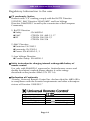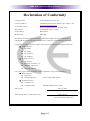
1
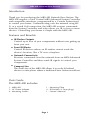
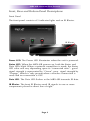
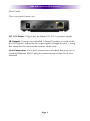
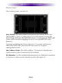
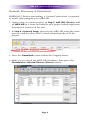
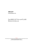
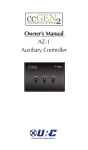
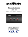
Owner’s Manual
MRX-4IR
Network Base Station
MRX-4IR Network Base Station Owners Manual ©2012 - 2014 Universal
Remote Control, Inc.
The information in this Owner’s Manual is copyright protected. No part of
this manual may be copied or reproduced in any form without prior
written consent from Universal Remote Control, Inc.
UNIVERSAL REMOTE CONTROL, INC. SHALL NOT BE LIABLE FOR
OPERATIONAL, TECHNICAL OR EDITORIAL ERRORS/OMISSIONS MADE
IN THIS MANUAL.
The information in this Owner’s Manual may be subject to change
without prior notice.
Total Control is a registered trademark of Universal Remote Control, Inc.
URC - Control the Experience is a registered trademark of Universal
Remote Control, Inc.
All other brand or product names are trademarks or registered trademarks
of their respective companies or organizations.
500 Mamaroneck Avenue, Harrison, NY 10528
Phone: (914) 835-4484 Fax: (914) 835-4532
TABLE OF CONTENTS
Introduction
1
Features and Benefits
1
Parts Guide
1
Front, Rear and Bottom Panel Descriptions
2
Network Installation
5
Network Discovery & Download
6
Optimizing IR Flasher Levels
7
Overview of IR Routing
8
Limited Warranty Statement
9
End User Agreement
11
Specifications
12
Federal Communication Commission
Interference Statement
13
Regulatory Information to the user
14
Declaration of Conformity
15
MRX-4IR NETWORK BASE STATION
Introduction
Thank you for purchasing the MRX-4IR Network Base Station. The
MRX-4IR requires a Total Control MRX Advanced System Controller
and compatible interfaces, programmed by a Custom Professional,
to control your home. Communicating over the network using WiFi, or a wired LAN connection, the MRX-4IR receives commands
from the System Controller and relays them, via IR, to four or more
devices. Controlling your home is simple with the MRX-4IR.
Features and Benefits
=
IR Flasher Outputs
Control up to four of your components without ever getting up
from your seat.
=
Front IR Blaster
Control IR devices where an IR emitter cannot reach the
device’s location, like a TV over a fireplace.
=
Network Connectivity
Receives commands over the network from an MRX Advanced
System Controller and then sends IR signals to control your
components.
=
Compact Size
The small size of the MRX-4IR allows it to easily fit behind
devices or into places where a traditional base station would not.
Parts Guide
The MRX-4IR includes:
1 - MRX-4IR
1 - AC Power Adapter
4 - Mounting Screws
1 - Mounting Plate
4 - IR Emitters (3.5mm plugs)
1 - Owner’s Manual
Page 1
MRX-4IR NETWORK BASE STATION
Front, Rear and Bottom Panel Descriptions
Front Panel
The front panel consists of 3 indicator lights and an IR Blaster.
IR Blaster
Power LED: The Power LED illuminates when the unit is powered.
Status LED: When the MRX-4IR powers up, both the Status and
Data LEDs blink. When a network connection is made, the Status
LED color will vary depending upon its “connected state”: good
signal strength is represented by “Green”, poor signal strength by
“Orange” (which is only present when a wireless connection is
used) and no connection is OFF.
Data LED: The Data LED flashes as the MRX-4IR transmits IR data.
IR Blaster: The front IR Blaster sends IR signals to one or more
components placed in direct line of sight.
Page 2
MRX-4IR NETWORK BASE STATION
Rear Panel
The rear panel ports are:
DC 12V Power: Plug in the included 12V DC 1A power supply.
IR Outputs: Connect an included 3.5mm IR emitter to each of the
four IR outputs. Adjust the IR output signal strength for port 1 using
the attenuator located on the bottom of the unit.
LAN Connection: If a wired connection is needed, this port uses a
standard Ethernet (RJ-45) plug to communicate via the local area
network.
Page 3
MRX-4IR NETWORK BASE STATION
Bottom Panel
The bottom panel consists of:
Reset Button: The Reset button is located on the bottom of the unit,
and requires a stylus, or paper clip to press the button. Pressing the
Reset button will cycle the MRX-4IR’s power. (Unplugging the MRX-4IR’s
power cable and then plugging it back in, also performs the same
function.)
Pressing and holding the Reset button for 15 seconds, will factory
default the MRX-4IR, and return the unit back to its original
unprogrammed state.
Mac Address Sticker: The MAC Address (12 numbers) identifies this
wireless device when connected to the network.
IR Attenuator: Use the included adjustment tool (or a flathead screwdriver)
to increase or decrease the intensity level for IR output #1.
Page 4
MRX-4IR NETWORK BASE STATION
Network Installation
WARNING!! Before proceeding, a Custom Professional is required
to install and configure your MRX-4IR.
The MRX-4IR is a network base station that allows full control of
your components with the use of Total Control MRX Advanced
System Controllers and compatible interfaces. Once installed on the
network, and a button is pressed on an interface, a command is
transferred over the customer’s network to the MRX Advanced
Network System Controller, which in turn is routed to the MRX-4IR
and then sends IR commands to the components you specify.
1. Connect the MRX-4IR onto the network (wired or wireless).
2. Connect your laptop into the same network as the MRX-4IR.
MRX-4IR
Wi-Fi Router
Page 5
MRX-4IR NETWORK BASE STATION
Network Discovery & Download
WARNING!! Before proceeding, a Custom Professional is required
to install and configure your MRX-4IR.
1. Open a new or current project. In Step 3: Add URC Devices, add
an MRX-4IR to a room included in your project which represents
the physical location of the unit.
2. In Step 6: Network Setup, discover the MRX-4IR using the same
process used for other Total Control network products in the
project.
3. Press the Download button within the Program menu.
4. Make sure to check the MRX-4IR checkbox, then press the
Download to Selected Devices (Direct) button.
Page 6
MRX-4IR NETWORK BASE STATION
Optimizing IR Flasher Levels
Test a few commands for each component before fixing the flasher
in place on the front panel of a device.
Since TiVo, Satellite Receivers and Cable Boxes are all extremely
sensitive to IR overload or saturation, you should test them
thoroughly. Put up the on screen guide and test the navigation
arrows. If operation is inconsistent or sluggish, lowerthe IR line
output for port 1 only and/or reposition the flasher.
If you still have sluggish operation, make sure IR routing is used
rather than ALL. When IR commands are sent to all the flashers in a
cabinet, you can have difficulty adjusting the IR Output. Program
URC Accelerator to send IR commands only via a specific IR port
(1-4), then readjust the IR Line Output level.
Connect an IR emitter to each IR output and run the emitter wire to
the IR receiver of each component. DO NOT STICK the emitter in
place yet. Adjust the LEVELon IR port 1 or adjust the emitter
PLACEMENT for ports 2-4 until the component responds to IR
commands then stick the emitter in place.
IR Outputs: These ports can be as discrete, ‘routed’ outputs that
only send IR commands to the specific component that each
emitter is attached. This assures accurate control in that a given
component’s commands are routed only to its dedicated IR output
and emitter, preventing IR oversaturation from multiple emitters
flashing at the same time.
POLARITY: Tip=IR data, Sleeve=GND.
Page 7
MRX-4IR NETWORK BASE STATION
Overview of IR Routing
There are several considerations to take into account when you are
installing an MRX-4IR to control an array of components:
1. When connecting a flasher from the MRX-4IR to your component make sure to notate the IR outputs being used. Program the
sameport designations into URC Accelerator.
2. Assigning each component with its own individualized port
number helps to control multiple components eliminating
interference.
3. Identical components must receive IR commands ONLY from a
dedicated flasher affixed to its front panel or a rear panel direct
IR input.
MRX-4IR
Wi-Fi Router
Page 8
MRX-4IR NETWORK BASE STATION
Limited Warranty Statement
1. Limited Warranty and Disclaimers
Universal Remote Control, Inc. (“URC”) warrants that the URC equipment shall
be free from defects in material and workmanship under normal usage for two
(2) years from purchase when such is purchased from URC. This limited
warranty is valid only in the United States of America. URC warrants that the
software will substantially conform in any material respect to its functional
specifications at the time of delivery. URC SHALL NOT BE LIABLE FOR
OPERATIONAL, TECHNICAL OR EDITORIAL ERRORS AND/OR
OMISSIONS MADE IN THE URC DOCUMENTATION. URC DOES NOT
WARRANT THAT THE URC SOFTWARE IS BUG-FREE OR ERROR FREE OR
THAT THERE ARE NO ERRORS/BUGS IN THE URC SOFTWARE.
URC warrants that at the time of purchase the URC equipment and the URC
software complied with all applicable regulations and policies of the Federal
Communications Commissions (“FCC”) regarding electromagnetic interference
caused by electronic/computing devices and to the extent that the URC
equipment and/or the URC software fails to so comply, URC shall, at its own
expense, take all reasonable measures to promptly cause such to comply.
URC equipment purchases from other than an authorized URC dealer or
distributor are without warranty.
THIS LIMITED WARRANTY DOES NOT COVER TECHNICAL ASSISTANCE
FOR HARDWARE OR SOFTWARE USAGE EXCEPT AS EXPRESSLY
PROVIDED FOR HEREIN, THE EQUIPMENT, SOFTWARE AND
DOCUMENTATION OF URC ARE SUPPLIED “AS IS” WITHOUT ANY
WARRANTY, EXPRESS, STATUTORY OR IMPLIED, OF ANY KIND. TO
THE MAXIMUM EXTENT PERMITTED BY APPLICABLE LAW, URC
EXPRESSLY DISCLAIMS ALL WARRANTIES, EXPRESS, STATUTORY OR
IMPLIED, INCLUDING BUT NOT LIMITED TO THE WARRANTIES OF
MERCHANTABILITY AND FITNESS FOR A PARTICULAR PURPOSE. URC
DOES NOT WARRANT, GUARANTEE, OR MAKE ANY
REPRESENTATIONS REGARDING THE USE OF, OR THE RESULTS OF THE
USE OF, THE EQUIPMENT, SOFTWARE OR DOCUMENTATION IN
TERMS OF CORRECTNESS, ACCURACY, RELIABILITY OR OTHERWISE.
EXCEPT AS EXPRESSLY PROVIDED FOR HEREIN, TECHNICAL SERVICES
ARE SUPPLIED “AS IS”, WITHOUT ANY WARRANTY, EXPRESS,
STATUTORY OR IMPLIED, OF ANY KIND. TO THE MAXIMUM EXTENT
PERMITTED BY APPLICABLE LAW, URC EXPRESSLY DISCLAIMS ALL
WARRANTIES, EXPRESS, STATUTORY OR IMPLIED, INCLUDING BUT
Page 9
MRX-4IR NETWORK BASE STATION
NOT LIMITED TO THE WARRANTIES OF QUALITY OR REASONABLE
SKILL AND CARE, OR OUTCOME OR RESULTS. WITHOUT IN ANY WAY
LIMITING THE GENERALITY OF THE OTHER PROVISIONS HEREIN,
WARRANTY DOES NOT COVER: (I) DAMAGE FROM MISUSE, NEGLECT
OR ACTS OF NATURE, (II) MODIFICATIONS, (III) INTEGRATION WITH
THIRD PARTY CONTENT (IV) BEYOND THE WARRANTY PERIOD AND/
OR FAILURE TO FOLLOW URC WARRANTY CLAIM PROCEDURE.
The warranty limitations and warranty disclaimers may not apply to end user in
whole or in part, where such are restricted or excluded by applicable law and
such shall apply to the maximum extent permitted by applicable law.
In the event of any warranty claim, URC will, at its sole option, repair the URC
equipment using new or comparable rebuilt parts, or exchange the URC
equipment for new or rebuilt equipment. In the event of a defect, these are the
end user’s exclusive remedies.
All the URC equipment returned for service, exchange or repair require an
RGA number. To obtain an RGA number, you must complete a Return
Request Form which you may obtain by calling (914) 835-4484 or contacting
URC at returnrequest@universalremote.com. To obtain warranty service, end
user must deliver the URC equipment, freight prepaid, in its original packaging
or packaging affording adequate protection to URC at 420 Columbus Avenue,
Valhalla, NY 10595. It is the end user’s responsibility to backup any macro
programming, artwork, software or other materials that may have been
programmed into the unit. It is likely that such data, software, or other materials
will be lost during service and URC will not be responsible for any such
damage or loss. A dated purchase receipt, bill of sale, installation contract or
other verifiable proof of purchase is required. For the URC equipment support
and other important information, please visit URC's website available at
www.universalremote.com or call the Customer Service Center at (914) 8354484.
This limited warranty only covers the URC equipment issues caused by defects
in material or workmanship during ordinary consumer use. It does not cover
product issues caused by any other reason, including but not limited to product
issues due to commercial use, acts of God, third-party installation, misuse,
limitations of technology, or modification of or to any part of the URC
equipment. This limited warranty does not cover the URC equipment sold as
used, as is, refurbished, so called "B stock" or consumables (such as batteries).
This limited warranty is invalid if the factory applied serial number has been
altered or removed from the URC equipment. This limited warranty
specifically excludes the URC equipment sold by unauthorized resellers.
Page 10
MRX-4IR NETWORK BASE STATION
With the exception of URC’s IR-only, broad-based consumer remotes, none of
URC’s PC programmable remotes or any of our Total Control® whole-house
equipment are authorized for online internet sales. Buying URC’s PC
programmable remotes or any of our Total Control® whole-house equipment
online means buying equipment that does not have a URC’s limited warranty.
Such equipment is not eligible for URC tech support or software support, either.
2. URC’S Limitations of Liability
IN NO EVENT SHALL URC BE LIABLE FOR INDIRECT, SPECIAL,
INCIDENTAL, EXEMPLARY, PUNITIVE OR CONSEQUENTIAL DAMAGES
OF ANY KIND OR LOSS OF PROFITS OR BUSINESS OPPORTUNITY, EVEN
IF URC IS ADVISED OF THE POSSIBILITY OF SUCH DAMAGES.
IN NO EVENT SHALL URC BE LIABLE FOR LOSS OF OR DAMAGE TO
DATA, COMPUTER SYSTEMS OR COMPUTER PROGRAMS. URC’S
LIABILITY, IF ANY, FOR DIRECT DAMAGES OF ANY FORM SHALL BE
LIMITED TO ACTUAL DAMAGES, NOT IN EXCESS OF AMOUNTS PAID
BY END USER FOR THE URC EQUIPMENT.
IN NO EVENT SHALL URC BE LIABLE FOR ANY EVENTS BEYOND ITS
CONTROL, INCLUDING ANY INSTANCE OF FORCE MAJEURE.
IN NO EVENT SHALL URC BE LIABLE FOR THE ACTS OR OMISSIONS OF
END USER OR ANY THIRD PARTY.
THE LIMITATIONS OF LIABILITY MAY NOT APPLY TO END USER IN
WHOLE OR IN PART, WHERE SUCH ARE RESTRICTED LIMITED OR
EXCLUDED BY APPLICABLE LAW AND SUCH SHALL APPLY TO THE
MAXIMUM EXTENT PERMITTED BY APPLICABLE LAW. URC SHALL NOT
BE HELD RESPONSIBLE FOR THE STATEMENTS MADE BY OTHERS.
SOME STATES OR JURISDICTIONS DO NOT ALLOW THE EXCLUSION OR
LIMITATION OF INCIDENTAL OR CONSEQUENTIAL DAMAGES, OR
ALLOW LIMITATIONS ON HOW LONG AN IMPLIED WARRANTY LASTS,
SO THE ABOVE LIMITATIONS OR EXCLUSIONS MAY NOT APPLY TO
END USER. THIS LIMITED WARRANTY GIVES END USER SPECIFIC LEGAL
RIGHTS AND END USER MAY HAVE OTHER RIGHTS WHICH VARY
FROM STATE TO STATE OR JURISDICTION TO JURISDICTION.
End User Agreement
The terms and conditions of the End User Agreement available at www.universalremote.com/eua.php shall apply.
Page 11
MRX-4IR NETWORK BASE STATION
Specifications
CPU : ARM 32-bit Cortex-M3(120MHz)
Memory : 128Kbyte SRAM, 768Kbyte Flash
Macro Capability : Up to 255 steps each
IR Range(Line of Sight via Infrared) : 30 to 50 feet, depending on
the environment
RF Range(radio frequency) : 50 to 100 feet, depending upon the
environment
Wi-Fi : IEEE 802.11 b/g/n
Weight : 3.0 oz
Size : 3.74” X 2.7” X 1.1”
Power : 12V DC 1A
Page 12
MRX-4IR NETWORK BASE STATION
Federal Communication Commission
Interference Statement
This equipment has been tested and found to comply with the limits for a
Class B digital device, pursuant to part 15 of the FCC Rules. These limits are
designed to provide reasonable protection against harmful interference in a
residential installation. This equipment generates, uses and can radiate radio
frequency energy and, if not installed and used in accordance with the
instructions, may cause harmful interference to radio communications.
However, there is no guarantee that interference will not occur in a particular
installation. If this equipment does cause harmful interference to radio or
television reception, which can be determined by turning the equipment off
and on, the user is encouraged to try to correct the interference by one more
of the following measures:
u Reorient or relocate the receiving antenna.
u Increase the separation between the equipment and receiver.
u Connect the equipment into an outlet on a circuit different from
that to which the receiver is connected.
u Consult the dealer or an experienced radio/TV technician for
help.
Warning!
Changes or modifications not expressly approved by the manufacturer could
void the user's authority to operate the equipment.
Note : The manufacturer is not responsible for any Radio or TV interference
caused by unauthorized modifications to this equipment. Such modifications
could void the user's authority to operate the equipment.
FCC Caution
This device complies with Part 15 of the FCC Rules. Operation is subject to the
following two conditions: (1) this device may not cause harmful interference,
and (2) this device must accept any interference received, including interference
that may cause undesired operation.
Any changes or modifications not expressly approved by the party responsible
for compliance could void the authority to operate equipment.
Federal Communication Commission (FCC) Radiation Exposure Statement
The device and the antenna for this device must be installed to ensure a minimum separation distance of 20 cm more from a person's body. Other operating
configurations should be avoided.
Page 13
MRX-4IR NETWORK BASE STATION
Regulatory Information to the user
n CE conformity Notice
Products with “CE” marking comply with the R&TTE Directive
1995/5/EC, EMC Directive 2004/108/EC and Low Voltage
Directive 2006/95/EEC issued by the commission of the European
Community.
1) R&TTE Directive
l Safety
: EN 60950-1
l EMC
: ETSI EN 301 489-1,3, 17
l RF
: ETSI EN 300 220-1,2
: ETSI EN 300 328
2) EMC Directive
l Emission: EN 55022
l Immunity: EN 55024
l Power: EN-61000-3-2, 3
3) Low Voltage Directive
l Product safety: EN 60950-1
n Safety instruction for charging internal rechargeable battery of
remote control
Use only with EN60950-1 approved as Limited power source and
double insulation() marked power adaptor & same ratings
described on the product label (12V DC 1A).
n Declaration of Conformity
“Hereby, Universal Remote Control Inc. declares that this MRX-4IR is
in compliance with the Essential requirements and other relevantprovisions of Directive 1999/5/EC.”
Certification
Type No.(Model No.)
Batch/Serial No.
Power Rating
Frequency band
MRX-4IR
12V
1.0A
Wi-Fi : IEEE 802.11 b/g/n
Page 14
MRX-4IR NETWORK BASE STATION
Declaration of Conformity
Company Name
:
Universal Remote Control Inc.
Company Address
:
Contact Information
:
500 Mamaroneck Avenue, Harrison, NY 10528, U.S.A
www.universalremote.com
Brand Name
:
Phone: (914)835-4484 Fax: (914)835-4532
UNIVERSAL remote control
Product Name
:
Base Station
Model Name
:
MRX-4IR
This product herewith complies with the requirements of EMC Directive (2004/108/EC)
and R&TTE Directive(1995/5/EC) issued by the Commission of the European Community
Compliance with these directives implies conformity to the following European Community
n EMC Directive
l
EN 55022
l
EN 55024
l
EN 61000-3-2
l
EN 61000-3-3
n R&TTE Directive
l
EN 60950-1
l
ETSI EN 301-489-1,3,17
l
ETSI EN 300 220-1,2
l
ETSI EN 300 328-
List of test reports and/or certificate verified compliance with the standards above
n EMC Directive
l
Report No.
l
Testing Laboratory
: Gumi College EMC Center
n R&TTE Directive
l
Certificate No.
l
Certificate Body
: SIEMIC Rheinland (No. 2200)
Date of issue
:
Name and signature of authorized person
:
Page 15
May 30, 2012
James Novak
Senior Product Manager
Universal Remote Control Inc.
500 Mamaroneck Avenue, Harrison, NY 10528
Phone: (914) 835-4484 Fax: (914) 835-4532
www.universalremote.com
OCE-0131A Rev 02