1
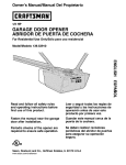
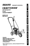
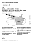
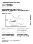
Owner's Manual/Manual
Del Propietario
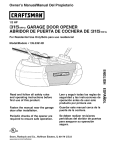
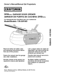
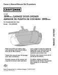
112 HP
GARAGE DOOR OPENER
ABRIDOR DE PUERTA DE COCHERA
For Residential
Model/Modelo
Use Only/S61o para uso residencial
139.5399211
m
m
Z_
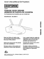
Read and follow all safety rules
and operating instructions before
first use of this product.
Leer y seguir todas las reglas de
seguridad y las instrucciones de
operaci6n antes de usar este
producto por primera vez.
Fasten the manual near the garage
door after installation.
Guardar este manual cerca de la
puerta de la cochera.
Periodic checks of the opener are
required to ensure safe operation.
Se deben realizar revisiones
peri6dicas del abridor de puertas
para asegurar su operaci6n
segura.
Sears, Roebuck
and Co.,
www.sears.com/craftsman
Hoffman
Estates,
IL 60179
U.S.A
TABLE
OF CONTENTS
Introduction
2.7
Adjustment
Section
27.29
Safety symbol and signal word review ........................ 2
Adjust the travel limits ...............................................
27
Preparing your garage door ........................................
Tools needed ...............................................................
Adjust the force .........................................................
28
Planning ..................................................................
3
3
Test the safety reversing sensor ............................... 29
4-5
Test the Protector System ®........................................
Carton inventory ..........................................................
6
Operation
Hardware inventory .....................................................
7
Operation safety instructions .....................................
29
30.34
30
Assembly
8-11
Assemble the rail .....................................................
8-9
Using your garage door opener ................................ 30
Fasten rail to motor unit and install trolley ................ 10
Attach rail brackets ....................................................
11
To open the door manually ........................................
Installation
Having a problem? ....................................................
33
Diagnostic Chart ........................................................
34
Using the watt-mounted Door Control ....................... 31
Care of your garage door opener .............................. 32
11.26
Installation safety instructions .................................... 11
Determine the header bracket location ..................... 12
Install the header bracket ..........................................
31
Programming
13
35-36
Attach the rail to the header bracket ......................... 14
To add or reprogram a hand-held remote control .....35
To erase all codes .....................................................
35
Install the Protector System ®................................ 15-17
3-Function Remote Control .......................................
Position the opener ...................................................
18
To add or change a Keyless Entry PIN ..................... 36
Hang the opener .......................................................
19
Repair
Parts
35
37.38
Install the door control and connect wiring ............... 20
Rail assembly parts ...................................................
37
Electrical requirements ..............................................
Installation parts ........................................................
37
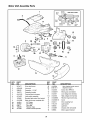
Motor unit assembly parts .........................................
38
21
Complete the sensor installation ............................... 21
Install the lights and lens ...........................................
22
Attach the emergency release rope and handle ....... 22
Fasten the door bracket ....................................... 23-24
Connect door arm to trolley ................................. 25-26
Accessories
39
Warranty
39
Service
Numbers
Back
cover
INTRODUCTION
Safety Symbol
and Signal Word Review
This garage door opener has been designed and tested to offer safe service provided it is installed, operated,
maintained and tested in strict accordance with the instructions and warnings contained in this manual.
When you see these Safety Symbols and Signal
Words on the following pages, they will alert you to
the possibility of serious injury or death if you do
not comply with the warnings that accompany them.
The hazard may come from something mechanical
or from electric shock. Read the warnings carefully.
Mechanical
Electrical
When you see this Signal Word on the following
pages, it will alert you to the possibility of damage to
your garage door and/or the garage door opener if
you do not comply with the cautionary statements
that accompany it. Read them carefully.
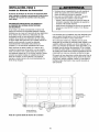
2
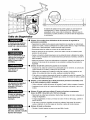
Preparing
your
garage
door
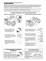
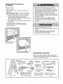
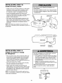
Before you begin:
• Disable locks.
To prevent possibleSERIOUSINJURY or DEATH:
• ALWAYScall a trained door systems technician if
garage door binds, sticks, or is out of balance.An
unbalancedgarage door may not reverse when
required.
• NEVERtry to loosen, move or adjust garage door, door
springs, cables, pulleys, brackets or their hardware, all
of which are under EXTREMEtension.
• Remove any ropes connected to garage door.
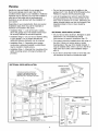
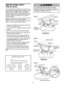
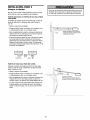
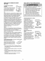
• Complete the following test to make sure your
garage door is balanced and is not sticking or
binding:
1. Lift the door about halfway as shown. Release
the door. If balanced, it should stay in place,
supported entirely by its springs.
• Disable ALL locks and remove ALL ropes connected to
garage door BEFOREinstalling and operating garage
door opener to avoid entanglement.
2. Raise and lower the door to see if there is any
binding or sticking.
If your door binds, sticks, or is out of balance, call a
trained door systems technician.
To prevent damage to garage door and opener:
• ALWAYSdisable locks BEFOREinstalling and operating
the opener.
• ONLYoperate garage door opener at 120V,60 Hz to
avoid malfunction and damage.
Sectional Door
One-Piece
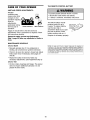
Tools
Door
needed
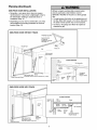
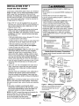
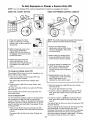
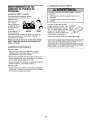
During assembly, installation and adjustment of the
opener, instructions will call for hand tools as
illustrated below.
Carpenter's
Level (optional)
_
_1
_
_
J_
_
Tape Measure
Hack Raw
_
_
_
Wire Cutters
3D/_'_
.Bit_16 .
and 5/32"
Claw Hammer
_
Pliers
0
-
_,_
_
_| _
\;_
"--'_
Screwdriver
Ad,ostab,e
Eod
Wre.o.
and 1/4"
3
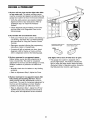
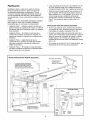
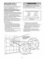
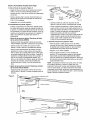
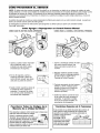
Planning
Identify the type and height of your garage door.
Survey your garage area to see if any of the
conditions below apply to your installation. Additional
materials may be required. You may find it helpful to
refer back to this page and the accompanying
illustrations as you proceed with the installation of
your opener.
Do you have an access door in addition to the
garage door? If not, Model 53702 Emergency Key
Release is required. See Accessories page.
Look at the garage door where it meets the floor.
Any gap between the floor and the bottom of the
door must not exceed 1/4" (6 mm). Otherwise, the
safety reversal system may not work properly. See
Adjustment Step 3. Floor or door should be
repaired.
Depending on your requirements, there are several
installation steps which may call for materials or
hardware not included in the carton.
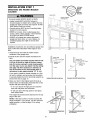
• Installation Step 1 - Look at the walt or ceiling
above the garage door. The header bracket must
be securely fastened to structural supports.
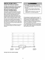
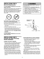
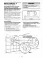
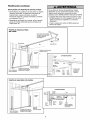
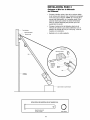
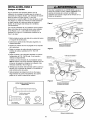
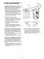
SECTIONAL DOOR INSTALLATIONS
Do you have a steel, aluminum, fiberglass or glass
panel door? If so, horizontal and vertical
reinforcement is required (Installation Step 12).
• Installation Step 6 - Do you have a finished ceiling
in your garage? If so, a support bracket and
additional fastening hardware may be required.
The opener should be installed above the center of
the door. If there is a torsion spring or center
bearing plate in the way of the header bracket, it
may be installed within 4 feet (1.22 m) to the left or
right of the door center. See Installation Steps 1
and 12.
• Installation Step 4 - Depending upon garage
construction, extension brackets or wood blocks
may be needed to install sensors.
• Installation Step 4 - Alternate floor mounting of the
safety reversing sensor will require hardware not
provided.
• If your door is more than 7 feet (2.13 m) high, see
rail extension kits listed on Accessories page.
SECTIONAL DOOR INSTALLATION
FINISHED CEILING
is required.
See page 19.
Horizontal and vertical reinforcement
is needed for lightweight garage doors
(fiberglass, steel, aluminum, door with
glass panels, etc.). See page 23 for details.
Rail
Header Wall
Motor unit
Wailmounted
Door
Control
CLOSED
Header
Bracket
Rail
Bracket
POSITION
Rail Assembly
©
_gZJ_
TrOlley
Stroairght _
E_eeragse2cY
Arm
Rope & Handle
o
Safety Reversing
Sensor
Safety Reversing Sensor
Gab between floor
and bottom of door
must not exceed 1/4" (6 mm).
._ader
all
rage
or
4
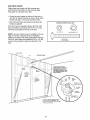
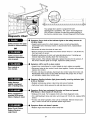
Door
Door
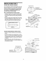
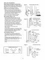
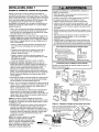
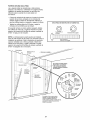
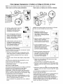
Planning
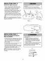
ONE-PIECE
(Continued)
DOOR INSTALLATIONS
Without a properly working safety reversal system,
persons (particularly small children) could be
SERIOUSLYINJUREDor KILLED by a closing garage
door.
• Generally, a one-piece door does not require
reinforcement. If your door is lightweight, refer to
the information relating to sectional doors in
Installation Step 12.
• The gap between the bottom of the garage door and
the floor MUST NOTexceed 1/4" (6 ram) Otherwise,
the safety reversal system may not work properly.
• The floor or the garage door MUST be repaired to
eliminate the gap
• Depending on your door's construction, you may
need additional mounting hardware for the door
bracket (Step 12).
ONE-PIECE
DOOR WITHOUT TRACK
Support bracket
& fastening
hardware is required.
See page 19
Header Wall
Motor unit
Rail
Walt-rnounted
Door Control
Access
Door
CLOSED
Rail
Bracket
POSITION
Rail Assembly
©
Emergency
Safer
Gapbetweenfloor
Sensor
Rope & Handle
Safety R_eversing Sensor and bottom of door must not exceed 1/4" (6mm).
leader _
Call
ONE-PIECE
Door
Arm
Door
Door
Arm
DOOR WITH TRACK
CLOSED POSITION
Rai!
/ Bracket
eader
Bracket
Trolley
Curved
_
Door Arm_
I
Rail Assembl
Door I
raoket
StraiOhl
Bm
ooooooooooo]
Garage
Door
Door
Arm
. Safety
Gap between floor
and bottom of door
ety
Reversing Sensor
Reversing
Sensor
must not exceed 1/4" (6 mm).
5
ncy Release
Rope & Handle
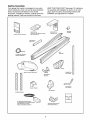
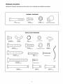
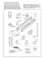
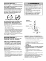
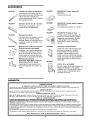
Carton
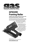
Inventory
Your garage door opener is packaged in one carton
which contains the motor unit and all parts illustrated
below. Accessories wilt depend on the model
purchased. If anything is missing, carefully check the
packing material. Parts may be stuck in the foam.
KEEP THE FOAM INTACT (see page 10). Hardware
for assembly and installation is shown on the next
page. Save the carton and packing material until
installation and adjustment is complete.
O
Premium Control Console
Sprocket
Coupling
SECU RITY.II,
Keyless Entry
SECURITY÷
Three-Function Remote Control
with Visor Clip (2)
BR
railcSu _
Rail
Assembly
2-Conductor Bell Wire
White & White/Red
Straight Door
Arm Section
Motor Unit with a Light Lens
Header/Rail
Brackets
Header
Curved Door
Arm Section
Bracket
Door Bracket
Hanging Brackets
Safety Label_
and
Literature
with attached 2-Conductor
White & WMte/Black Bell Wire
Safety Reversing Sensor
Mounting Bracket (2)
6
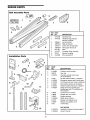
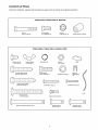
Hardware
Inventory
Separate all hardware and group as shown below for the assembly and installation procedures.
ASSEMBLY HARDWARE
Bolt
1/4-20xl-3/4"
(8)
Hex Bolt
1/4"-20x5/8"
Lock Nut
1/4"-20x7/16
(4)
INSTALLATION
Wing Nut
1/4"-20 (2)
Ring
Fastener
Sprocket
Coupling Sleeve
HARDWARE
0
Carriage Bolt
1/4"-20xl/2"
(2)
(12)
©
Nut 5/16"-18 (6)
Handle
(3)
©
Lag Screw
5/16"-9xl-5/8"
Hex Bott
5/16"-18x7/8"
(2)
Lag Screw
5/16"-18x1-7/8"
(4)
Lock Washer
Screw
6ABx1-1/4"
(2)
(2)
5/16" (6)
Insulated
Staples (30)
Screw 6-32x1"(2)
Rope
Cardage Bolt
5/16"-18x2-1/2"(2)
D_y Wall Anchors (2)
o_
Clevis Pin
5/16"x2-3/4"(1)
Clevis Pin
5/16"x1" (1)
7
Clevis Pin
5/16"xlq/4"
(1)
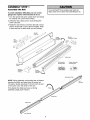
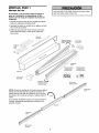
ASSEMBLY
Assemble
STEP
the
1
Rail
To prevent INJURYfrom pinching, keep hands and
fingers away from the joints while assembling the rail.
To avoid installation difficulties, do not run the
garage door opener until instructed to do so.
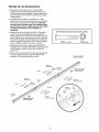
1. Turn the opened rail carton upside down and empty
its contents onto a level work surface.
2. Unfold the rails, taking care to avoid kinking the
screw rod joints.
3. Rotate the rail sections so that the flat side is down
and the screw side is up for all three lengths. Keep
it clean and free of debris while you are working.
Straight
Door Arm
Extend
End Rails
Outward
Rail
Support
Braces
Remove
Cardboard
Packing
Center
Rail
Trolley Rack
Chassis Assembly
Hardware Bag
Rail Assembly
Hardware Bag
Rail Assembly
Carton
Extend
End Rails
Cardboard
Packing
Outward
Sprocket
NOTE: During assembly, avoid pulling the rail section
housing the trolley rack away from the screw rod.
The rack is factory set about 9" (23 cm) from the end
of the screw rod to the center of the rack.
End Rail
Rail
Sprocket
If the plastic liner slides part way out during
assembly, simply push it back in.
Rotate
Center Rail
Trolley Rack
Door End Rail
8
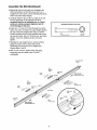
Assemble
the
Rail
(Continued)
4. Beginning with the sprocket end, straighten the
three rail sections so that the screw rod is in a
straight line at the joints. (Avoid handling the joints,
which may have sharp edges.)
5. Carefully slide the pins at the top edge of the rail
into the openings on the adjacent rail. It is
essential that the rail assembly be on a level
surface to achieve proper alignment and to
avoid damage to the pins.
HARDWARE
6. Insert two 1/4"-20xt-3/4" bolts through the center
holes of a brace, and place its open length against
the rail at the joint, aligning the holes as shown.
Position another brace on the opposite side of the
rail over the bolts, add 1/4"-20 lock nuts, and hand
tighten. Insert two additional bolts and hand
tighten.
SHOWN
ACTUAL
SIZE
lllllllllllllllllll]
@
Bolt
t/4"-20x1-3/4"
Lock NUt
1/4"-20
(8)
7. Keeping the rail straight and on a level surface,
grasp the screw rods on each side of the
remaining joint and pivot into a straight line.
Repeat steps 5 and 6.
8. With a 7/16" wrench, tighten bolts until snug,
beginning with the center holes. Do NOT
overtighten.
Sprocket End
(Back)
Rail
Suppo_
Brace
Alignment
Hole
Slide end rail
f
Rail
Support
Brace
Rail Pin
Lock
Nuts
Alignment
Hole
Center Rail
Door End
(Front)
_lide end rail
toward center rail
Bolts
1/4"-20xt
9
-3/4"
toward center rail
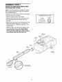
ASSEMBLY
STEP
2
Fasten
the
and Install
Rail To the
the Trolley
Motor
Unit
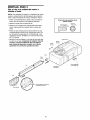
NOTE: To aid in assembly and installation, replace
the foam packing around the motor unit. Remove it
after Installation Step 4.
• Working on a level surface, align the rail assembly
with the motor unit, as shown.
HARDWARE
SHOWN
• Slip the coupling over the rail sprocket.
• Slide the rail through the motor unit bracket until
the coupling fits securely over the motor unit
sprocket.
Hex BoIt
1/4"-20x5/8"
• Align the two bolt holes in the rail with those in the
motor unit bracket. Insert two 1/4"-20x5/8" hex
bolts and lock nuts. Tighten securely with a 7/16"
socket wrench.
ACTUAL
SIZE
Lock Nut
1/4"-20
©
• Slide the trolley onto and along the bottom of the
rail until it snaps firmly in place. Be certain to
install it facing correcUy: the trolley release
arm must be horizontal (lock position), with its
arrow pointed away from the motor unit.
Motor Unit
Sprocket
Motor Unit
Bracket
Coupling
Rail
Sprocket
Rait
Assembly
Hex Bolts
1/4"-20x5/8"
Foam Packaging
Trolley
Arrow must point
toward garage door
Release
arm
10
ASSEMBLY
Attach
the
STEP
Rail
Lock Nuts
3
1/4"-2o
Brackets
j
Rail
Brackets
• Align rail brackets to end of rail assembly, as
shown.
• Insert two 1/4"-20 x 5/8" hex bolts and lock nuts.
Tighten securely with a 7/16" socket.
Hex Bolts
1/4"-20x5/8
You have now finished assembling your garage
door opener. Please read the following warnings
before proceeding to the installation section,
Rail
HARDWARE
SHOWN ACTUAL
Hex Bolt
1/4"-20x5/8"
SIZE
Lock Nut
1/4"-20
@
INSTALLATION
IMPORTANT
INSTALLATION
INSTRUCTIONS
To reduce the risk of severe injury or death:
1. READAND FOLLOWALL INSTALLATIONWARNINGS
AND INSTRUCTIONS.
8. NEVERwear watches, rings or loose clothing while
installing or servicing opener.They could be caught in
garage door or opener mechanisms.
9. Install wall-mounted garage door control:
• within sight of the garage door.
• out of reach of children at minimum height of 5 feet
2. Install garage door opener only on properly balanced
and lubricated garage door. An improperly balanced
door may not reverse when required and could result in
SEVEREINJURY or DEATH.
3. All repairs to cables, spring assemblies and other
hardware MUST be made by a trained door systems
technician BEFOREinstalling opener.
4. Disable all locks and remove all ropes connected to
garage door BEFOREinstalling opener to avoid
entanglement.
5. Install garage door opener 7 feet (2.13 m) or more
above floor.
(1.5m).
• away from all moving parts of the door.
10. Placeentrapment warning label on wall next to garage
door control.
11. Place manual release/safety reverse test label in plain
view on inside of garage door.
12. Upon completion of installation, test safety reversal
system. Door MUST reverse on contact with a
1-1/2" (3.8 cm) high object (or a 2x4 laid flat) on
the floor.
6. Mount emergency releasehandle 6 feet (1.83 m) above
floor.
7. NEVERconnect garage door opener to power source
until instructed to do so.
11
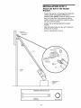
INSTALLATION
STEP
1
Determine
the Header Bracket
Location
Ceilin
OPTIONAL
CEILING
g
MOUNT
FOR
HEADER
BRACKET
Unfinishe_
Header Wall
Vertical Centerline
of Garage Door
To prevent possible SERIOUSINJURY or DEATH:
• Header bracket MUST be RIGIDLYfastened to
structural support on header wall or ceiling, otherwise
garage door might not reverse when required. DONOT
install header bracket over drywall.
• Concrete anchors MUST be used if mounting header
bracket or 2x4 into masonry.
• NEVERtry to loosen, move or adjust garage door,
springs, cables, pulleys, brackets, or their hardware,
all of which are under EXTREMEtension.
2x4
Structural
Supports
• ALWAYScall a trained door systems technician if
garage door binds, sticks, or is out of balance. An
unbalanced garage door might not reverse when
required.
installation procedures vary according to garage door
types. Follow the instructions which apply to your
door.
1. Close the door and mark the inside vertical
centerline of the garage door.
2. Extend the line onto the header wall above the
door.
Header Wall
r'_'_3"
You can fasten the header bracket within 4 feet
(1.22 m) of the left or right of the door center
only if a torsion spring or center bearing plate
is in the way; or you can attach it to the ceiling
(see page 13) when clearance is minimal. (It
may be mounted on the wall upside down if
necessary, to gain approximately 1/2" (1 cm).
(7.5 cm)Track
r'_'--3"
Header Wall
(7.5 cm_Track
of Travel
Highest Point
Door
I7
If you need to install the header bracket on a 2x4
(on wall or ceiling), use lag screws (not provided)
to securely fasten the 2x4 to structural supports as
shown here and on page 13.
Sectional
door with curved track
One-piece
door with horizontal
track
3. Open your door to the highest point of travel as
shown. Draw an intersecting horizontal line on the
header walt above the high point:
• 3" (7.5 cm) above the high point for sectional
door and one-piece door with track.
Header Wall
• 8" (20 cm) above the high point for one-piece
door without track.
Header Wall
This height wilt provide travel clearance for the top
edge of the door.
NOTE: If the total number of inches exceeds the
height available in your garage, use the maximum
height possible, or refer to page 13 for ceiling
installation.
Door
Highest
Pivot
One-piece door without track:
jamb hardware
12
One_piece door without track:
pivot hardware
INSTALLATION
STEP
2
Install the Header Bracket
Wall Mounting
Holes
You can attach the header bracket either to the wall
above the garage door, or to the ceiling. Follow the
instructions which will work best for your particular
requirements. Do not install the header bracket
over drywall. If installing into masonry, use
concrete anchors (not provided).
The nail hole is for
_ positioning only.
You must use lag screws
to mount the header bracket.
WALL HEADER BRACKET INSTALLATION
Optional
Wall Mounting
• Center the bracket on the vertical centedine with
the bottom edge of the bracket on the horizontal
line as shown (with the arrow pointing toward the
ceiling).
Holes
• Mark the vertical set of bracket holes (do not use
the holes designated for ceiling mount). Drill 3/16"
pilot holes and fasten the bracket securely to a
structural support with the hardware provided.
HARDWARESHOWNACTUALSIZE
Door
Lag Screw
5/16"-9xl-5/8"
Vertical
Centedine
Hiagrhag_et
Po°inrtT°rfavel
CEILING HEADER BRACKET INSTALLATION
• Extend the vertical centeriine onto the ceiling as
shown.
• Center the bracket on the vertical mark, no more
than 6" (15 cm) from the walt. Make sure the arrow
is pointing away from the wall. The bracket can be
mounted flush against the ceiling when clearance
is minimal.
/
1/
• Mark the side holes. Drill 3/16" pilot holes and
fasten bracket securely to a structural support with
the hardware provided.
_
/f
- Finished Ceiling -
_//Header
Bracket
VerticaICentedine
Maximum
Door
Lag Screws
5/16"-9xl -5/8"
Ceiling Mounting Holes
Header Wail
The nail hole is for
positioning only.
You must use lag screws
to mount the header bracket.
13
INSTALLATION
STEP
3
Attach the Rail to the Header
Bracket
Position the opener on the garage floor below the
header bracket. Use packing material as a
protective base. NOTE: If the door spring is in the
way you'll need help. Have someone hold the
opener securely on a temporary support to allow
the raft to clear the spring.
Position the rail bracket against the header
bracket.
Align the bracket holes and join with a clevis pin
5/16"x2-3/4" as shown.
Insert a ring fastener to secure.
_r Wall
J
t Reader Bracket
Ring Fastener
Header Bracket
\
Clevis
Pin
5/16"x2-3/4"
Rail
Bracket
Garage
Door
_]
HARDWARE
SHOWN
ACTUAL
or
SIZE
o]
Clevis Pin
5/16"x2-3/4"
Temporary
Support
OpenerCa_ton
©
Ring Fastener
14
INSTALLATION
Install
STEP
The Protector
4
System _
• Be sure power is not connected to the garage door
opener BEFOREinstalling the safety reversing sensor.
• To prevent SERIOUSINJURYor DEATHfrom a closing
garage door:
- Correctly connect and align the safety reversing
sensor. This required safety device MUST NOT be
disabled.
The safety reversing sensor must be connected
and aligned correctly before the garage door
opener will move in the down direction.
IMPORTANT INFORMATION ABOUT
THE SAFETY REVERSING SENSOR
- Install the safety reversing sensor so beam is NO
HIGHERthan 6" (15 cm) above garage floor.
When properly connected and aligned, the sensor
will detect an obstacle in the path of its electronic
beam. The sending eye (with an orange indicator
light) transmits an invisible light beam to the
receiving eye (with a green indicator light). If an
obstruction breaks the light beam while the door is
closing, the door will stop and reverse to full open
position, and the opener lights will flash 10 times.
If it is necessary to mount the units on the wall, the
brackets must be securely fastened to a solid
surface such as the wall framing. Extension brackets
(see accessories) are available if needed, if
installing in masonry construction, add a piece of
wood at each location to avoid drilling extra holes in
masonry if repositioning is necessary.
The units must be installed inside the garage so that
the sending and receiving eyes face each other
across the door, no more than 6" (15 cm) above the
floor. Either can be installed on the left or right of the
door as long as the sun never shines directly into the
receiving eye lens.
The invisible light beam path must be unobstructed.
No part of the garage door (or door tracks, springs,
hinges, rollers or other hardware) may interrupt the
beam while the door is closing.
The mounting brackets are designed to clip onto the
track of sectional garage doors without additional
hardware.
Sensor Beam
6" (15 cm) max.
above floor
SensorBeam
6" (15 cm) max.
above floor
Invisible Light Beam
Protecflon Area
Facing the door from inside the garage
15
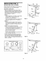
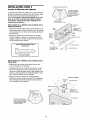
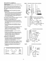
INSTALLING THE BRACKETS
Be sure power to the opener is disconnected.
install and align the brackets so the sensors will face
each other across the garage door, with the beam no
higher than 6" (15 cm) above the floor. They may be
installed in one of three ways, as follows.
Figure
DOOR TRACK
MOUNT
(RIGHT SIDE)
Door
Track
\
Garage door track installation
(preferred):
Lip
Indicator
Light
• Slip the curved arms over the rounded edge of
each door track, with the curved arms facing the
door. Snap into place against the side of the track.
It should lie flush, with the lip hugging the back
edge of the track, as shown in Figure 1.
Sensor
Bracket
If your door track will not support the bracket
securely, walt installation is recommended.
Wall installation (Figure 2 & 3):
• Place the bracket against the walt with curved
arms facing the door. Be sure there is enough
clearance for the sensor beam to be unobstructed.
WALL MOUNT (RIGHT
Figure 2
Lag
• If additional depth is needed, an extension bracket
(See Accessories) or wood blocks can be used.
Screws (Not Provided)
Indicator
• Use bracket mounting holes as a template to
locate and drill (2) 3/16" diameter pilot holes on
the wall at each side of the door, no higher than 6"
(15 cm) above the floor.
Light
-crews_
S re_cSkOr
t
ag Sews
Len
.......
• Attach brackets to wall with lag screws
(Not provided).
• If using extension brackets or wood blocks, adjust
right and left assemblies to the same distance out
from the mounting surface. Make sure ait door
hardware obstructions are cleared.
Floor installation
SIDE)
Fasten Wood Block to Wall with
Figure 3
WALL MOUNT (RIGHT SIDE)
Extension
Bracket
(See Accessories)
(Figure 4):
• Use wood blocks or extension brackets (See
Accessories) to elevate sensor brackets so the
lenses will be no higher than 6" (15 cm) above the
floor.
• Carefully measure and place right and left
assemblies at the same distance out from the walt.
Be sure all door hardware obstructions are
cleared.
• Fasten to the floor with concrete anchors as
shown.
Lens
Figure 4
HARDWARE
SHOWN
ACTUAL
Light
FLOOR MOUNT
(RIGHT SIDE)
SIZE
A_ach with
Concrete Ancho_
(Not Provided)
Carriage Bolt
1/4"-20xl/2"
Wing Nut
1/4"-20
Staples
Light
Bracket
16
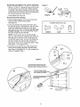
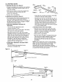
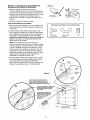
MOUNTING AND WIRING THE SAFETY SENSORS
Figure 5
• Slide a 1/4"-20xl/2" carriage bolt head into the slot
on each sensor. Use wing nuts to fasten sensors
to brackets, with lenses pointing toward each other
across the door. Be sure the lens is not obstructed
by a bracket extension (see Figure 5).
CarriageBolt
• Finger tighten the wing nuts.
Recommended
"-"_
Wing Nut
1/4"-20x1/2"
Wire Routing
1. Using insulated staples, run the wires from both
sensors to the rail at the door header
(see Figure 6).
HARDWARE
2. Cross and twist the two wires where they meet
the rail (see Figure 6, Illustration A). Run the wires
inside the channels at the top of the rail, along
each side, to the motor unit. Do net use the lower
(trolley) channels. Use a screwdriver tip to tuck
the wires snugly into the channels.
SHOWN
Carriage Bolt
I/4"-20xl/2"
ACTUAL
SIZE
Wing Nut
1/4"-20
Staples
NOTE: ff your access door is near the garage
door, you may choose to install the door control at
this time and run the door control wire along the
rail with the sensor wires. Use one rail channel for
the door control wire and the other channel for
both sensor wires. If you choose this option, follow
instructions 1-3 on page 20 now.
3. Pull wires taut across the top of the chassis and
insert into the opening above the terminal block
(see Figure 6, Illustration B). You will complete the
wiring in Installation Step 7.
A
Header
Wall
Sensor
Wire
Twist
Wires
Sensor
Wire
Header
Bracket
Figure 6
Rail
Channel
t. Run wires from sensors to end of rail
at the door header. Cross & twist here to
help
contain
wires
in channels
on top
of rail.
Bell Wire
B
2. Run wires along channels
to motor unit. Use screwdrive
to tuck snugly into channels.
blade
3. Pull wires taut across top of chassis
and insert into opening above
terminal block.
Sensor
17
invisible Light Beam
Protection Area
Sensor
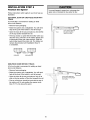
INSTALLATION
Position
the
STEP
5
Opener
To prevent damage to garage door, rest garage door
opener rail on 2x4 placed on top section of door.
Follow instructions which apply to your door type as
illustrated.
SECTIONAL DOOR OR ONE-PIECE DOOR WITH
TRACK
A 2x4 laid fiat is convenient for setting an ideal
door-to-rail distance.
• Remove foam packaging.
• Raise the opener onto a stepladder. You wilt need
help at this point if the ladder is not tall enough.
• Open the door all the way and place a 2x4 laid fiat
on the top section beneath the rail.
• If the top section or panel hits the trolley when you
raise the door, pull down on the trolley release arm
to disconnect inner and outer sections. Slide the
outer trolley toward the motor unit. The trolley can
remain disconnected until Installation Step 13
is completed.
_
Release Ar
Trolley
ENGAGED
ONE-PIECE
RELEASED
U
DOOR WITHOUT TRACK
A 2x4 on its side is convenient for setting an ideal
door-to-rail distance.
• Remove foam packaging.
• Raise the opener onto a stepladder. You wilt need
help at this point if the ladder is not tall enough.
I
• Open the door all the way and place a 2x4 on its
side on the top section of the door beneath the rail.
\
• The top of the door should be level with the top of
the motor unit. Do not position the opener more
than 3" (7.5 cm) above this point.
18
INSTALLATION
STEP
6
Hang the Opener
To avoid possible SERIOUSINJURYfrom a falling
garage door opener,fasten it SECURELYto structural
supports of the garage. Concrete anchors MUST be used
if installing any brackets into masonry.
Three representative installations are shown. Yours
may be different. Hanging brackets should be angled
(Figure 1) to provide rigid support. On finished
ceilings (Figure 2), attach a sturdy metal bracket to
structural supports before installing the opener. This
bracket and fastening hardware are not provided
(see accessories).
Figure 1
'Structural
Existing brackets from a previous installation may be
fastened to the sides of the motor unit as in
Figures 1 and 2, or to the mounting tabs as shown in
Figure 3. Then continue with step 5 below.
Lag Screws
5/16"- 18xl-7/8"
Measure
Distance
1. Measure the distance from each side of the motor
unit to the structural support.
Hex Bolt
5/16"-18x7/8"
2. Cut both pieces of the hanging bracket to required
lengths.
Nuts 5/16"-18
3. Drill 3/16" pilot holes in the structural supports.
4. Attach one end of each bracket to a support with
5/16"-18xl-7/8" lag screws.
Preferred range of
bracket placement
5. Fasten the opener to the hanging brackets with
5/16"-18x7/8" hex bolts, lock washers and nuts.
If you wish to utilize the two center mounting tabs,
you must triangulate the vertical brackets for
additional stability. See Figure 3.
6. Check to make sure the rail is centered over the
door (or in line with the header bracket if the
bracket is not centered above the door).
Bracket
(Not Provided)
7. Remove the 2x4. Operate the door manually. If
the door hits the rail, raise the header bracket.
NOTE: DO NOT connect power to opener at this
time.
Boff 5/16"-18x7/8"
Lock Washer 5/16"
Nut 5116"-18
Bolt 5/16"-18x7/8"
Lock Washer 5/16"\
Nut 5/16"-18
HARDWARESHOWNACTUALSIZE
Preferred range of
bracket placement
Hex Boff
5/16"- 18x718"
©
Nut 5/16"-18
Figure 3
©
Exist#
Brackets
Top Mounting Tabs
Lock Washer 5/16"
Bracket
o
_o
Utilizing existing installation
19
_
=
INSTALLATION
STEP
Install the Door Control
7
To prevent possible SERIOUSINJURYor DEATHfrom
electrocution:
Locate door control within sight of door, at a minimum
height of 5 feet (1.52 m) where small children cannot
reach, away from moving parts of door and door
hardware. If installing into drywall, drill 5/32" holes and
use the anchors provided. For pre-wired installations
(as in new home construction), it may be mounted to
a single gang box (Figure 2).
• Be sure power is not connected BEFOREinstalling door
control.
• Connect ONLYto 24 VOLTlow voltage wires.
To prevent possible SERIOUSINJURYor DEATHfrom a
closing garage door:
• Install door control within sight of garage door, out of
reach of children at a minimum height of 5 feet
(1.52 m), and away from all moving parts of door.
• NEVERpermit children to operate or play with door
control push buttons or remote control transmitters.
• Activatedoor ONLYwhen it can be seenclearly,is properly
adjusted,and there are no obstructionsto door travel.
• ALWAYSkeep garage door in sight until completely
closed. NEVERpermit anyone to cross path of closing
garage door.
1. Strip 7/16" (11 mm) of insulation from one end of
bell wire and connect to the two screw terminals on
back of door control by color: white wire to 2 and
white/red wire to the 1.
2. Remove white cover by gently prying at slot inside
of the cover with a small fiat head screwdriver.
Fasten with 6ABx1-1/4" self-tapping screws (drywall
installation) or 6-32x1" machine screws (into gang
box) as follows:
• Drill and install bottom screw, allowing 1/8" (3 mm)
to protrude above walt surface.
• Position bottom of door control on screw head and
slide down to secure. Adjust screw for snug fit.
HARDWARE
SHOWN ACTUAL
SIZE
insulated
Staples
Control Console (std installation)
• Drill and install top screw with care to avoid
cracking plastic housing. Do not over tighten.
• Insert top tabs and snap on cover.
Control Console (pre-wired)
3. (Standard installation only) Run bell wire up wall
and across ceiling to motor unit. Use insulated
staples to secure wire in several places. Do not
pierce wire with a staple, creating a short or open
circuit. If your access door is near the garage door,
you may run this wire with the Safety Reversing
Sensor wires along the top of the rail. See page 17.
Drywall Anchors
Outside Keylock Accessory Connections
To opener quick-connect terminals: white to white;
white/red to red.
CONTROL
CONSOLE
4. Insert all wires through the opening on top of motor
unit above the terminal block on the back panel
(Figure 3).
Top
Mounting
Lighted
Push
5. Strip 7/16" (11 mm) of insulation from each set of
wires. Insert door control wire into quick-connect
terminals by color: white wire to white, white/red
wire to red.
Button
Lig
Bottom
Lock BACK VIEW
Mounting
Figure 1
REMOVE
Separate white and white/black wires sufficiently to
connect to the opener quick-connect terminals.
Twist like colored wires together. Insert wires into
quick-connect holes: white to white and white/black
to grey.
NOTE: When connecting multiple door controls to the
opener, twist same color wires together. Insert wires
into quick-connect holes: white to white and red/white
to red.
COVER
PRE-WIRED
INSTALLATION
To Remove,
_
Tabs
_
First ///_ _/-_
_
Twist
Here
Figure 3 Wiring to Terminal Block
6. Use tacks or staples to permanently attach
Strip 7/16" (11 ram) of insulation from each wire.
insert wires through opening on top of motor
entrapment warning label to wall near door control,
unit above terminal block, then into quickand manual release/safety reverse test label in a
prominent location on inside of garage door.
connect terminals.
/
/\
the
Door Control
To release wire, push in tab
NOTE: DO NOT connect the power and operate _
Connection, withscrewdriverlnverbp
_tip
I
opener at this time. The trolley will travel
_
to the full open position but will not return
€--7116
--_
to the close position until the sensor
Strip wire 7/16"
beam is connected and properly aligned.
2O
Hole
Figure 2
& REPLACE
TO Replace,
insert Top
Hole
Terminal
Screws
24 Volt
2-Condu_or
Bell Wi_
INSTALLATION
Electrical
STEP
8
Requirements
To preventpossible SERIOUSINJURYor DEATHfrom
electrocution or fire:
To avoid installation difficulties, do not run the
opener at this time.
• Be sure power is not connected to the opener, and
disconnect power to circuit BEFOREremoving cover to
establish permanent wiring connection.
• Garagedoor installation and wiring MUST be in
compliance with all local electrical and building codes.
• NEVERuse an extension cord, 2-wire adapter, or
change plug in any way to make it fit outlet. Be sure
the opener is grounded.
To reduce the risk of electric shock, your garage door
opener has a grounding type plug with a third
grounding pin. This plug will only fit into a grounding
type outlet. If the plug doesn't fit into the outlet you
have, contact a qualified electrician to install the
proper outlet.
RIGHO
WRON O
PERMANENT WIRING
CONNECTION
If permanent wiring is required by your local
code, refer to the following procedure.
To make a permanent connection through the 7/8"
hole in the top of the motor unit:
• Remove the motor unit cover screws and set the
cover aside.
Ground Tab
\\
Green
Ground Screw
Black
Wire
• Remove the attached 3-prong cord.
• Connect the black (line) wire to the screw on the
brass terminal; the white (neutral) wire to the
screw on the silver terminal; and the ground wire
to the green ground screw. The opener must be
grounded.
• Reinstall the cover.
To avoid installation difficulties, do not run the
opener at this time.
INSTALLATION
STEP
Complete
the Safety
Sensor Installation
9
TROUBLESHOOTING
Reversing
THE SAFETY SENSORS
1. If the sending eye indicator light does not glow
steadily after installation, check for:
• Electric power to the opener.
• A short in the white or white/black wires. These
can occur at staples, or at opener connections.
• Incorrect wiring between sensors and opener.
• A broken wire.
ALIGNING THE SAFETY SENSORS
• Plug in the opener. The indicator lights in both the
sending and receiving eyes will glow steadily if
wiring connections and alignment are correct.
2. If the sending eye indicator light glows steadily but
the receiving eye indicator light doesn't:
The sending eye orange indicator light will glow
regardless of alignment or obstruction. If the green
indicator light in the receiving eye is off, dim, or
flickering (and the invisible light beam path is not
obstructed), alignment is required:
• Check alignment.
• Check for an open wire to the receiving eye.
3. If the receiving eye indicator light is dim, realign
either sensor.
• Loosen the sending eye wing nut and readjust,
aiming directly at the receiving eye. Lock in place.
NOTE: When the invisible beam path is obstructed
or misaligned while the door is closing, the door will
reverse. If the door is already open, it will not close.
The opener lights will flash 10 times. (See page 15.)
• Loosen the receiving eye wing nut and adjust the
sensor until it receives the sender's beam. When
the green indicator light glows steadily, tighten the
wing nut.
21
INSTALLATION
STEP
Install
and
the
Lights
10
Lens
To prevent possible OVERHEATINGof the endpanel or
light socket,
• DONOT use short neck or specialty light bulbs.
• DONOT use halogen bulbs. Use ONLYincandescent.
• Install a 100 watt maximum light bulb in each
socket. The lights will turn ON and remain lit for
approximately 4-1/2 minutes when power is
connected. Then the lights will turn OFE
• Insert bottom lens tabs into slots on chassis. Tilt
towards chassis to engage top tabs, then drop
down gently into place. (See illustration.)
Top Lens Tab
Lens
• To remove, depress both top lens tabs. Tilt lens
slightly outward and down, then pull out to clear
bulbs. Use care to avoid snapping off bottom lens
tabs.
NOTE: Use only standard light bulbs. The use of
short neck or speciafity light bulbs may overheat the
endpanel or light socket.
Bottom
Chassis Slots
nL_oL
O © O © © u
\
Bottom
Chassis Slot
INSTALLATION
STEP
Attach
the Emergency
Rope and Handle
TOp
LensTab
4
Insert Bottom
Lens Tabs First
11
Release
To prevent possible SERIOUSINJURYor DEATHfrom a
falling garage door:
• If possible, use emergency releasehandle to
disengage trolley ONLYwhen garage door is
CLOSED.Weak or broken springs or unbalanced
door could result in an open door falling rapidly
and/or unexpectedly.
• NEVERuse emergency releasehandle unless garage
doorway is clear of persons and obstructions.
NEVERuse handle to pull door open or closed. If rope
knot becomes untied, you could fall.
• Thread one end of the rope through the hole in the
top of the red handle so "NOTICE" reads right side
up as shown. Secure with an overhand knot at
least 1" (2.5 cm) from the end of the rope to
prevent slipping.
• Thread the other end of the rope through the hole
in the release arm of the outer trolley.
• Adjust rope length so the handle is 6 feet (1.83 m)
above the floor. Ensure that the rope and handle
clear the tops of all vehicles to avoid
entanglement. Secure with an overhand knot.
Trolley
NOTE: If it is necessary to cut the rope, heat seal
the cut end with a match or lighter to prevent
unraveling.
T_eaYse Arm_ °m
22
Overhand
INSTALLATION
Fasten
the
Door
STEP
12
Bracket
Fiberglass,aluminum or lightweight steel garage doors
Will. REQUIREreinforcement BEFOREinstallation of
door bracket. Contact your door manufacturer for
reinforcement kit.
Follow instructions which apply to your door type
as illustrated below or on the following page.
A horizontal reinforcement brace should be long
enough to be secured to two vertical supports. A
vertical reinforcement brace should cover the
height of the top panel.
HARDWARE
G
The illustration shows one piece of angle iron as the
horizontal brace. For the vertical brace, two pieces of
angle iron are used to create a U-shaped support
(Figure 1). The best solution is to check with your
garage door manufacturer for an opener installation
door reinforcement kit.
SHOWN
ACTUAL SIZE
Nut 5/16"-18
NOTE: Many vertical brace installations provide for
direct attachment of the clevis pin and door arm. In
this case you will not need the door bracket; proceed
to Installation Step 12.
©
LockWasher
5/16"
Carriage Bolt
5/f6"-f8x2-1/2"
SECTIONAL DOORS
• Center the door bracket on the previously marked
vertical centerline used for the header bracket
installation. Note correct UP placement, as
stamped inside the bracket (Figure 2).
• Position the bracket on the face of the door within
the following limits:
• Mark and drill 5/16" left and right fastening holes.
Secure the bracket as shown in Figure 1 if there is
vertical reinforcement.
If your installation doesn't require vertical
reinforcement but does need top and bottom
fastening holes for the door bracket fasten as shown
in Figure 2.
A) The top edge of the bracket 2"-4" (5-10 cm)
below the top edge of the door.
B) The top edge of the bracket directly below any
structural support across the top of the door.
Horizontal and vertical reinforcement
is needed for lightweight
garage doors
(fiberglass, aluminum, steel, doors with
Veriical
Figure 1
23
ONE-PIECE DOORS
Please read and comply with the warnings and
reinforcement instructions on the previous page.
They apply to one-piece doors also.
• Center the door bracket on the top of the door, in
line with the header bracket as shown. Mark either
the left and right, or the top and bottom holes.
• Drill 5/16" pilot holes and fasten the bracket with
hardware supplied.
HARDWARE
SHOWN
ACTUAL
©
If the door has no exposed framing, drill 3/16" pilot
holes and fasten the bracket with 5/16"x1-1/2" lag
screws (not provided) to the top of the door.
©
Nut 5/16"-18
NOTE: The door bracket may be installed on the top
edge of the door if required for your installation.
(Refer to the dotted line optional placement drawing.)
Drill 3/16" pilot holes and substitute 5/16"xl- 1/2" lag
screws (not provided) to fasten the bracket to the
door.
SIZE
LockWasher
5/t6"
Carriage Bolt
5/16"q 8x2-1/2"
Header Wall
2x4
Finished Ceiling
Horizontal and vertical
reinforcement is needed for
._doors
(fiberglass,
aluminum, steel,
door with glass panel, etc.).
(Not Provided)
Header
Bracket
Door
Bracket
Optional
Placement
of Door
Bracket
®
Vertical
Centarline
of Garage
Door
_Lock Washer
'i
5/16"
i
I
'
Top of Door
/
_
J,)
l/
'_Cardage
For a door with no exposed framing,
or for the optional installation, use
5/16"xt-1/2"
lag screws (Not provided)
to fasten door bracket.
24
Jh
(Inside Garage
TopEdge
opt,ooa,
Placement
Bolt
5/16"- 18x2-1/2"
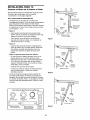
INSTALLATION
Connect
Door
STEP
Arm
13
to Trolley
o
inner
Outer
Trolley
Trolley
Follow instructions which apply to your door type as
illustrated below and on the following page.
SECTIONAL
DOORS ONLY
Fa tooe,
5% 'x1 io
?;i;221
i
• Make sure garage door is fully closed. Pull the
emergency release handle to disconnect the outer
trolley from the inner trolley. Slide the outer trolley
back (away from the door) about 2" (5 cm) as
shown in Figures 1, 2 and 3.
;
Door
Rae_lSee
_E_O;i;_A
• Figure 1:
- Fasten straight door arm section to outer trolley
with the 5/16"xl" clevis pin. Secure the
connection with a ring fastener.
- Fasten curved section to the door bracket in the
same way, using the 5/16"xl-1/4" clevis pin.
Oo_
_-
Emergency
Clevis Pin
5/16"x1-1/4"
Figure 1
• Figure 2:
- Bring arm sections together. Find two pairs of
holes that line up and join sections. Select holes
as far apart as possible to increase door arm
rigidity.
• Figure 3, Hole alignment
alternative:
- If holes in curved arm are above holes in straight
arm, disconnect straight arm. Cut about 6"
(15 cm) from the solid end. Reconnect to trolley
with cut end down as shown.
- Bring arm sections together.
- Find two pairs of holes that line up and join with
bolts, lock washers and nuts.
• Pull the emergency release handle toward the
opener at a 45 ° angle so that the trolley release
arm is horizontal. Proceed to Adjustment Step 1,
page 27. Trolley will re-engage automatically when
opener is operated.
HARDWARE
SHOWN ACTUAL
Figure 2
SIZE
©©0
Nut 5/16"-18
C
Lock Washer 5/16"
°lC
Clevis Pin
5/16"x1" (Trolley)
Clevis Pin
5/16"x1_1/4"
Lock
Washers
5/16"
Ring Fastener
Nuts
5/16"d6
ol
(Door Bracket)
Hex Bolt
5/16"-18x7/8"
_x7/8"
Cut this end
Figure 3
25
ALL ONE-PIECE DOORS
1.Assemble
Door
Bracket
the door arm, Figure 4:
Fastener
• Fasten the straight and curved door arm sections
together to the longest possible length (with a 2
or 3 hole overlap).
Clevis Pin
Figure 4
Strai ht
5/16
5"/1'_48x7/8_
• On one-piece doors, before connecting the door
arm to the trolley, the travel limits must be
adjusted. Limit adjustment screws are located on
the left side panel as shown on page 27. Follow
adjustment procedures below.
- Manually close the door and lift the door arm to
the trolley. The arm should touch the trolley just
ahead of the door arm connector hole. Refer to
the fully closed trolley/door arm positions in the
illustration. If the arm is behind the connector
hole, adjust the limit further. One full turn equals
2" (5 cm) of trolley travel.
° Open door adjustment: decrease UP
travel limit
- Turn the UP limit adjustment screw
counter-clockwise 4 turns.
3. Connect
the door arm to the trolley:
• Close the door and join the curved arm to the
connector hole in the trolley with the remaining
clevis pin. It may be necessary to lift the door
slightly to make the connection.
- Press the Door Control push button. The trolley
wilt travel to the fully open position.
- Manually raise the door to the open position
(parallel to the floor), and lift the door arm to the
trolley. The arm should touch the trolley just in
back of the door arm connector hole. Refer to
the fully open trolley/door arm positions in the
illustration. If the arm does not extend far
enough, adjust the limit further. One full turn
equals 2" (5 cm) of trolley travel.
• Secure with a ring fastener.
Run the opener through a complete travel cycle.
If the door has a slight "backward" slant in full
open position as shown in the illustration,
decrease the UP limit until the door is parallel
to the floor.
NOTE: When setting the up limit on the following
page, the door should not have a "backward' slant
when fully open as illustrated below. A slight
backward slant will cause unnecessary bucking
and/or jerking operation as the door is being opened
or closed from the fully open position.
• Closed door adjustment: decrease DOWN
travel limit
- Turn the DOWN limit adjustment screw
clockwise 4 complete turns.
Figure 5
Fu!ly Closed
Trolley
Door Arm
Connector
Hole
Emergency
_Door
- _Curved
- Press the Door Control push button. The trolley
will travel to the fully closed position.
Figure 5:
Inner Trolley
5/16"-18
Door Arm
• Secure with a ring fastener.
o
Nuts
Lock
WasherS
• With the door closed, connect the straight door
arm section to the door bracket with the
5/16"xl - 1/4" clevis pin.
2. Adjustment procedures,
Ring
Release Handle
Arm
Closed
Inner Trolley
Open Door
(incorrect)
26
ADJUSTMENT
Adjust
Limits
the
UP and
STEP
DOWN
1
Travel
Without a properlyinstalledsafety reversal system,
persons(particularly small children) could be
SERIOUSLYINJUREDor KILLED by a closing garage
door.
Limit adjustment settings regulate the points at which
the door wilt stop when moving up or down.
• Incorrect adjustment of garage door travel limits will
interfere with proper operation of safety reversal
system.
• If one control (force or travel limits) is adjusted, the
other control may also need adjustment.
• After ANY adjustments are made, the safety reversal
system MUST be tested. Door MUST reverse on
contact with 1-1/2" high (3.8 cm) object (or 2x4 laid
flat) on floor.
To operate the opener, press the Door Control push
bar. Run the opener through a complete travel cycle.
• Does the door open and close completely?
• Does the door stay closed and not reverse
unintentionally when fully closed?
If your door passes both of these tests, no limit
adjustments are necessary unless the reversing test
fails (Adjustment Step 3, page 29).
Adjustment procedures are outlined below. Read the
procedures carefully before proceeding to
Adjustment Step 2. Use a screwdriver to make limit
adjustments. Run the opener through a complete
travel cycle after each adjustment.
To prevent damageto vehicles, be sure fully open door
provides adequateclearance.
NOTE: Repeated operation of the opener during
adjustment procedures may cause the motor to
overheat and shut oft Simply wait 15 minutes and
try again.
I
NOTE: If anything interferes with the door's upward
travel, it will stop. If anything interferes with the
door's downward travel (including binding or
unbalanced doors), it will reverse.
/
O0000OO0
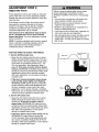
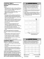
HOW AND WHEN TO ADJUST THE LIMITS
Limit
Adjustment
Screws
• If the door does not open completely but opens
at least five feet (1.5 m):
Left Side Panel
Increase up travel. Turn the UP limit adjustment
screw clockwise. One turn equals 2" (5 cm) of
travel.
NOTE: To prevent the trolley from hitting the cover
protection bolt, keep a minimum distance of 2-4"
(5 cm - 10 cm) between the trolley and the bolt.
i_++_djust
• If door does not open at least 5 feet (1.5 m):
UP Travel
Adjust DOWN Travel
Adjust the UP (open) force as explained in
Adjustment Step 2.
• If the door reverses when closing and there is
no visible interference to travel cycle:
• If the door does not close completely:
Increase down travel. Turn the down limit
adjustment screw counterclockwise. One turn
equals 2" (5 cm) of travel.
If the opener lights are flashing, the Safety
Reversing Sensors are either not installed,
misatigned, or obstructed. See Troubleshooting,
page 21.
If door still won't close completely and the trolley
bumps into the pulley bracket (page 4), try
lengthening the door arm (page 25) and
decreasing the down limit.
Test the door for binding: Pull the emergency
release handle. Manually open and close the door.
If the door is binding or unbalanced, call for a
trained door systems technician. If the door is
balanced and not binding, adjust the DOWN
(close) force. See Adjustment Step 2.
• If the opener reverses in fully closed position:
Decrease down travel. Turn the down limit
adjustment screw clockwise. One turn equals 2"
(5 cm) of travel.
27
ADJUSTMENT
Adjust
STEP
2
the Force
Without a properly installed safety reversal system,
persons (particularly small children) could be
SERIOUSLYINJUREDor KILLED by a closing garage
door.
Force adjustment controls are located on the back
panel of the motor unit. Force adjustment settings
regulate the amount of power required to open and
close the door.
• Too much force on garage door will interfere with
proper operation of safety reversal system.
• NEVERincrease force beyond minimum amount
required to close garage door.
• NEVERuse force adjustments to compensate for a
binding or sticking garage door.
• If one control (force or travel limits) is adjusted, the
other control may also need adjustment.
• After ANY adjustments are made, the safety reversal
system MUST be tested. Door MUST reverse on
contact with 1-1/2" high (3.8 cm) object (or 2x4 laid
flat) on floor.
If the forces are set too light, door travel may be
interrupted by nuisance reversals in the down
direction and stops in the up direction. Weather
conditions can affect the door movement, so
occasional adjustment may be needed.
The maximum force adjustment range is about
3/4 of a complete turn. Do not force controls
beyond that point. Turn force adjustment controls
with a screwdriver.
NOTE: If anything interferes with the door's upward
travel, it will stop. If anything interferes with the
door's downward travel (including binding or
unbalanced doors), it will reverse.
HOW AND WHEN TO ADJUST THE FORCES
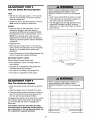
1. Test the DOWN (close)
Force Adjustment
Controls
force
Back Panel
• Grasp the door bottom when the door is about
halfway through DOWN (close) travel. The door
should reverse. Reversal halfway through down
travel does not guarantee reversal on a 1-1/2"
(3.8 cm) obstruction. See Adjustment Step 3,
page 29. If the door is hard to hold or doesn't
reverse, DECREASE the DOWN (close) force by
turning the control counterclockwise. Make small
adjustments until the door reverses normally.
After each adjustment, run the opener through a
complete cycle.
• If the door reverses during the down (close)
cycle and the opener lights aren't flashing,
INCREASE DOWN (close) force by turning the
control clockwise. Make small adjustments until
the door completes a close cycle. After each
adjustment, run the opener through a complete
travel cycle. Do not increase the force beyond the
minimum amount required to close the door.
Force
2. Test the UP (open) force
• Grasp the door bottom when the door is about
halfway through UP (open) travel. The door
should stop. If the door is hard to hold or
doesn't stop, DECREASE UP (open) force by
turning the control counterclockwise. Make small
adjustments until the door stops easily and opens
fully. After each adjustment, run the opener
through a complete travel cycle.
• If the door doesn't open at least 5 feet (1.5 m),
INCREASE UP (open) force by turning the
control clockwise. Make small adjustments until
door opens completely. Readjust the UP limit if
necessary. After each adjustment, run the opener
through a complete travel cycle.
28
DOWN
Force
ADJUSTMENT
Test the Safety
STEP
3
Reversal
System
Without a properly installed safety reversal system,
persons (particularly small children) could be
SERIOUSLYINJUREDor KILLED by a closing garage
door.
TEST
• With the door fully open, place a 1-1/2" (3.8 cm)
board (or a 2x4 laid flat) on the floor, centered
under the garage door.
• Safety reversal system MUST be tested every month.
• If one control (force or travel limits) is adjusted, the
other control may also need adjustment.
• After ANY adjustments are made, the safety reversal
system MUST be tested. Door MUST reverse on
contact with 1-1/2" high (3.8 cm) object (or 2x4 laid
flat) on the floor.
• Operate the door in the down direction. The door
must reverse on striking the obstruction.
ADJUST
• If the door stops on the obstruction, it is not
traveling far enough in the down direction.
Increase the DOWN limit by turning the DOWN
limit adjustment screw counterclockwise 1/4 turn.
NOTE: On a sectional door, make sure limit
adjustments do not force the door arm beyond a
straight up and down position. See the illustration
on page 25.
• Repeat the test.
• When the door reverses on the 1-1/2" (3.8 cm)
board, remove the obstruction and run the opener
through 3 or 4 complete travel cycles to test
adjustment.
• If the unit continues to fail the Safety Reverse Test,
call for a trained door systems technician.
IMPORTANT SAFETY CHECK:
Test the Safety Reverse System after:
• Each adjustment of door arm length, limits, or
force controls.
1-f/2" (3.8 cm) board
(or a 2x4 laid flat)
• Any repair to or adjustment of the garage door
(including springs and hardware).
• Any repair to or buckling of the garage floor.
• Any repair to or adjustment of the opener.
ADJUSTMENT
Test
The
Protector
STEP
4
System
Without a properly installed safety reversing sensor,
persons (particularly small children) could be
SERIOUSLYINJUREDor KILLED by a closing garage
door.
_
• Press the remote control push button to open the
door.
• Place the opener carton in the path of the door.
• Press the remote control push button to close the
door. The door will not move more than an inch
(2.5 cm), and the opener lights will flash.
The garage door opener will not close from a remote
if the indicator light in either sensor is off (alerting
you to the fact that the sensor is misaligned or
obstructed).
If the opener closes the door when the safety
reversing sensor is obstructed (and the sensors
are no more than 6" (15 cm) above the floor), call
for a trained door systems technician.
Safety Reversing Sensor
29
Safety Reversing
Sensor
OPERATION
IMPORTANT
SAFETY INSTRUCTIONS
To reduce the risk of severe injury or death:
1. READAND FOLLOWALL WARNINGSAND
INSTRUCTIONS.
9. If one control (force or travel limits) is adjusted, the
other control may also need adjustment.
2. ALWAYSkeep remote controls out of reach of children.
NEVERpermit children to operate or play with garage
door control push buttons or remote controls.
3. ONLYactivate garage door when it can be seen clearly, it
is properly adjusted, and there are no obstructions to
door travel.
4. ALWAYSkeep garage door in sight until completely
closed. NO ONESHOULDCROSSTHE PATHOFTHE
MOVINGDOOR.
5. NO ONESHOULDGO UNDERA STOPPED,PARTIALLY
OPENEDDOOR.
6. If possible, use emergency release handle to disengage
trolley ONLYwhen garage door is CLOSED.Weak or
broken springs or unbalanced door could result in an
open door falling rapidly and/or unexpectedly.
7. NEVERuse emergency releasehandle unless garage
doorway is clear of persons and obstructions.
8. NEVERuse handle to pull garage door open or closed. If
rope knot becomes untied, you could fall.
Using
Your
Garage
Door
10. After ANY adjustments are made, the safety reversal
system MUST be tested.
11. Safety reversal system MUST be tested every month.
Garagedoor must reverse on contact with 1-1/2" high
(3.8 cm) object (or a 2x4 laid flat) on the floor.
12. ALWAYSKEEPGARAGEDOOR PROPERLYBALANCED
(see page 3). An improperly balanceddoor may not
reverse when required and could result in SEVERE
INJURYor DEATH.
13. All repairs to cables, spring assemblies and other
hardware, all of which are under EXTREMEtension,
MUST be made by a trained door systems technician.
14. ALWAYSdisconnect electric power to garage door
opener BEFOREmaking any repairs or removing
covers.
15SAVETHESEINSTRUCTIONS.
6. If obstructed while opening, the door will stop.
7. If fully open, the door will not close when the beam
is broken. The sensor has no effect in the opening
cycle.
Opener
Your Security,I _ opener and hand-held remote
control have been factory-set to a matching code
which changes with each use, randomly accessing
over 100 billion new codes. Your opener will operate
with up to eight Security,l_ remote controls and one
Security.l_ Keyless Entry System. If you purchase a
new remote, or if you wish to deactivate any remote,
follow the instructions in the Programming section.
If the sensor is not installed, or is misaligned, the
door won't close from a hand-held remote. However,
you can close the door with the Door Control, the
Outdoor Key Switch, or Keyless Entry, if you activate
them until down travel is complete. If you release
them too soon, the door will reverse.
Activate your opener with any of the following:
• The hand-held Remote Control'. Hold the large
push button down until the door starts to move.
• The wall-mounted Door Control: Hold the push
button or bar down until the door starts to move.
The opener lights will turn on under the following
conditions: when the opener is initially plugged in;
when power is restored after interruption; when the
opener is activated.
They will turn off automatically after 4-1/2 minutes or
provide constant light when the Light feature on the
Premium Control Console is activated. Bulb size is
100 watts maximum.
• The Keyless Entry (See Accessories): If provided
with your garage door opener, it must be
programmed before use. See Programming.
When the opener is activated (with the safety
reversing sensor correctly installed and aligned)
Security4 _ light feature: Lights will also turn on
when someone walks through the open garage door.
With a Premium Control Console, this feature may be
turned off as follows: With the opener lights off, press
and hold the light button for 10 seconds, until the
light goes on, then off again. To restore this feature,
start with the opener lights on, then press and hold
the light button for 10 seconds until the light goes off,
then on again.
1. If open, the door will close. If closed, it wilt open.
2. If closing, the door will reverse.
3. If opening, the door will stop.
4. If the door has been stopped in a partially open
position, it will close.
5. If obstructed while closing, the door will reverse. If
the obstruction interrupts the sensor beam, the
opener lights will blink for five seconds.
3O
Using the Wall.Mounted
Door Control
THE PREMIUM CONTROL
CONSOLE
To Open
the
Door
Manually
Lighted
Press the lighted push button to
open or close the door. Press
again to reverse the door during
the closing cycle or to stop the
door while it's opening.
To prevent possible SERIOUSINJURYor DEATHfrom a
falling garage door:
• If possible, use emergency releasehandle to
disengage trolley ONLYwhen garage door is
CLOSED.Weak or broken springs or unbalanced
door could result in an open door falling rapidly
and/or unexpectedly.
Light
Button
Lock
utton
Light feature
• NEVERuse emergency releasehandle unless garage
doorway is clear of persons and obstructions.
NEVERuse handle to pull door open or closed. If rope
knot becomes untied, you could fall.
Press the Light button to turn the opener light on or
off. It will not control the opener lights when the door
is in motion. If you turn it on and then activate the
opener, the light wilt remain on for 4-1/2 minutes.
Press again to turn it off sooner. The 4-1/2 minute
interval can be changed to 1-1/2, 2-1/2, or 3-1/2
minutes as follows: Press and hold the Lock button
until the light blinks (about 10 seconds). A single blink
indicates that the timer is reset to 1-1/2 minutes.
Repeat the procedure and the light will blink twice,
resetting the timer to 2-1/2 minutes. Repeat again for
a 3-1/2 minute interval, etc., up to a maximum of four
blinks and 4-1/2 minutes.
DISCONNECT THE TROLLEY:
The door should be fully
closed if possible. Pull down
on the emergency release
handle (so that the trolley
release arm snaps into a
vertical position) and lift the
door manually. The lockout
feature prevents the trolley
from reconnecting
automatically, and the door
can be raised and lowered
manually as often as
necessary.
Lock feature
Designed to prevent operation of the door from
hand-held remote controls. However, the door will
open and close from the Door Control, the Outdoor
Key Switch and the Keyless Entry Accessories.
To activate, press and hold the Lock button for 2
seconds. The push button light will flash as long as
the Lock feature is on.
Re_ease Arm
Trolley
(in Manual
|]_
_
Disconnect
Position)
Lockout position
(Manual disconnect)
TO RE-CONNECT THE
TROLLEY:
To turn off, press and hold the Lock button again for
2 seconds. The push button light will stop flashing.
The Lock feature will also turn off whenever the
"learn" button on the motor unit panel is activated.
Pull the emergency release
handle toward the opener at
an angle so that the trolley
release arm is horizontal. The
trolley will reconnect on the
next UP or DOWN operation,
either manually or by using
the door control or remote.
Additional feature when used with the 3-Function
hand-held remote
To control the opener lights:
In addition to operating the door,
you may program the remote to
operate the lights.
1. With the door closed, press and hold a small
remote button that you want to control the light.
2. Press and hold the Light button on the door
control.
3. While holding the Light button, press and hold the
Lock button on the door control.
4. After the opener lights flash, release all buttons.
31
Trolley
Emergency
__Trolley
Release
Release
Arm
(Pull at 45 ° angle)
To reconnect
CARE
OF YOUR
OPENER
THEREMOTE
CONTROL
BATTERY
LIMIT AND FORCE ADJUSTMENTS:
Weather
conditions may
cause some minor
changes in door
operation requiring
some readjustments,
particularly during
the first year of
operation.
To prevent possible SERIOUSINJURYor DEATH:
• NEVERallow small children near batteries.
• If battery is swallowed, immediately notify doctor.
FORCE
CONTROLS
The lithium battery should
produce power for up to
5 years. To replace battery,
use the visor clip or
screwdriver blade to pry open
the case as shown. Insert
battery positive side up (+).
LIMIT CONTROLS
Pages 27 and 28 refer to the limit and force
adjustments. Only a screwdriver is required. Follow
the instructions carefully.
Dispose of old battery properly.
Repeat the safety reverse test (Adjustment
Step 3, page 29) after any adjustment of limits or
force.
MAINTENANCE
Open this end
first to avoid
cracking
SCHEDULE
Once a Month
NOTICE: To comply with FCC and or h]dustly Canada _ules (IC), adjustment or
modifications of this receiver and/or tlansmitMr are prohibited, exceptfor changing the
code setting or repiacg]gthe battery THEREARENO OTHERUSERSERVICEABLEPARTS
Testedto Comply with EBBStandalds FORHOMEOR OFFICEUSE.Operation is subject to
the following lwo conditions: (f) this device may not cause harmful interfelence, and
(2) this device must accept any interference _eceived,including interference that may
cause undesired operation
• Manually operate door. If it is unbalanced or
binding, call a trained door systems technician.
• Check to be sure door opens & closes fully. Adjust
limits and/or force if necessary. (See pages 27
and 28)
• Repeat the safety reverse test. Make any
necessary adjustments. (See Adjustment Step 3)
Once a Year
• Oil door rollers, bearings and hinges. The opener
does not require additional lubrication. Do not
grease the door tracks.
32
HAVING
A PROBLEM?
1. My door will not close
on my motor unit: The
must be connected and
garage door opener wilt
and the light bulbs blink
safety reversing sensor
aligned correctly before the
move in the down direction.
• Verify the safety sensors are properly installed,
aligned and free of any obstructions. Refer to
Installation Step 10: Install The Protector
SysterrP.
• Check diagnostic LED for flashes on the motor
unit then refer to the Diagnostic Charton the
following page.
2. My remotes
will not activate the door:
• Verify your Premium door control is not blinking. If
it is blinking, deactivate the Lock Mode following
the instructions for Using the Premium Control
Console.
Sending Eye Safety Sensor
(Amber Indicator Light)
• Reprogram remotes following the programming
instructions. Refer to Programming.
Receiving Eye Safety Sensor
(Green Indicator Light)
• If remote will still not activate your door, check
diagnostic LED for flashes on motor unit then
refer to Diagnostic Chart on the following page.
3. My door reverses for no apparent reason:
Repeat safety reverse test after adjustments to
force or travel limits. The need for occasional
adjustment for the force and limit settings is normal.
Weather conditions in particular can affect door
travel.
5. My lights will not turn off when door is open:
• The garage door opener is equipped with a
security light feature. This feature activates the
light on when the safety sensor beam has been
obstructed. Refer to Operation section; Using the
Wall Mounted Door Control, Light Feature.
• Manually check door for balance or any binding
problems.
• Refer to Adjustment Step 2, Adjust the Force.
4. My door reverses for no apparent reason after
fully closing and touching the floor: Repeat
safety reverse test after adjustments to force or
travel limits. The need for occasional adjustment for
the force and limit settings is normal. Weather
conditions in particular can affect door travel.
• Refer to Adjustment Step 1, Adjust the UP and
DOWN Travel Limits. Decrease down travel by
turning down limit adjustment screw clockwise.
33
Your garage door opener is programmed with
self-diagnostic capabilities. The "Learn" button/diagnostic
LED will flash a number of times then pause signifying it
has found a potential issue. Consult Diagnostic Chart below.
Diagnostic
Chart
Symptom: One or both of the Indicator lights on the safety sensors do
not glow steady.
• Inspect sensor wires for a short (staple in wire), correct wiring polarity
(black/white wires reversed), broken or disconnected wires, replace/attach
as needed.
• Disconnect all wires from back of motor unit.
Safety sensors wire open
(broken or disconnected).
OR
• Remove sensors from brackets and shorten sensor wires to 1-2 ft (30-60 cm)
from back each of sensor.
• Reattach sending eye to motor unit using shortened wires. If sending eye
indicator light glows steadily, attach the receiving eye.
• Align sensors, if the indicator lights glow replace the wires for the sensors. If
the sensor indicator lights do not light, replace the safety sensors.
Safety sensors wire
shorted or black/white
wire reversed.
Symptom: LED is not lit on door control.
• Inspect door control/wires for a short (staple in wire), replace as needed.
• Disconnect wires at door control, touch wires together. If motor unit activates,
replace door control.
• If motor unit does not activate, disconnect door control wires from motor unit.
Momentarily short across red and white terminals with jumper wire. If motor
unit activates, replace door control wires.
Door control or
wire shorted.
Symptom: Sending indicator light glows steadily, receiving indicator light
is dim or flashing.
• Realign receiving eye sensor, clean lens and secure brackets.
Safety Sensors
slightly misaligned
(dim or flashing LED).
• Verify door track is firmly secured to wall and does not move.
Symptom: Motor has overheated; the motor unit does not operate
RPM Sensor = Short travel 6-8" (15-20 cm).
• Unplug unit to reset. Try to operate motor unit, check diagnostic code.
Motor overheated or
possible RPM sensor
failure. Unplug to reset.
• If it is still flashing 5 times and motor unit moves 6-8" (15-20 cm), replace RPM
sensor.
• If motor unit doesn't operate, motor unit is overheated. Wait 30 minutes and
retry. If motor unit still will not operate replace logic board.
"0
Motor Circuit
Failure.
Symptom: Motor unit doesn't operate.
• Replace logic board because motor rarely fails.
Replace Receiver
Logic Board.
34
PROGRAMMING
NOTICE: If this Security,_ garage door opener is operated with a non-rolling code transmitter, the technical
measure in the receiver of the garage door opener, which provides security against code-theft devices, will be
circumvented. The owner of the copyright in the garage door opener does not authorize the purchaser or
supplier of the non-rolling code transmitter to circumvent that technical measure.
Your garage door opener has already been programmed at the factory to operate with your hand-held remote
control. The door will open and close when you press the large push button.
Below are instructions for programming your opener to operate with additional Security+ ®remote controls.
To Add
USING THE "LEARN"
or Reprogram
a Hand.held
BUTTON
1. Press end hold the button on the
hand-held remote* that you wish
to operate your garage door.
2. While holding the ENTER button,
press and hold the LIGHT button
on the Premium Control Console.
2. Within 30 seconds, press and
hold the button on the hand-held
remote* that you wish to operate
your garage door.
3. Continue holding the ENTER and
LIGHT buttons while you press
the push bar on the Premium
Control Console (all three buttons
are held).
3. Release the button when the
motor unit lights blink. It has
learned the code. If light bulbs are
not installed, two clicks will be
heard.
All Codes
From
Unit Memory
Control
USING THE PREMIUM CONTROL CONSOLE
1. Press end release the "learn"
button on the motor unit. The
learn indicator light will glow
steadily for 30 seconds.
To Erase
Remote
4. Release buttons when the motor
unit lights blink. It has learned the
code. If light bulbs are not
installed, two clicks will be heard.
Motor
*3.Function
Remotes
If provided with your garage door opener, the large
button is factory programmed to operate it. Additional
buttons on any
Security+ ®3-Function
remote or compact
remote can be
programmed to operate
other Security+ ® garage
door openers.
To deactivate any unwanted remote,
first erase all codes:
Press and hold the "learn" button on
motor unit until the learn indicator light
goes out (approximately 6 seconds). All
previous codes are now erased. Reprogram each
remote or keyless entry you wish to use.
35
To Add,
Reprogram
or
NOTE: Your new Keyless Entry must be programmed
USING THE "LEARN"
Change
a Keyless
Entry
PIN
to operate your garage door opener.
BUTTON
USING THE PREMIUM CONTROL CONSOLE
1. Press and release the "learn"
button on motor unit. The learn
indicator light will glow steadily for
30 seconds.
NOTE: This method requires two people if the Keyless
Entry is already mounted outside the garage.
1. Enter a four digit personal
identificationnumber (PIN) of your
choice on the keypad. Then press
and hold ENTER.
2. Within 30 seconds, enter a four
digit personal identification
number (PIN) of your choice on
the keypad. Then press and hold
the ENTER button.
2. While holding the ENTER button,
press and hold the LIGHT button
on the Premium Control Console.
3. Release the button when the
motor unit lights blink. It has
learned the code. If light bulbs are
not installed, two clicks will be
heard.
3. Continue holding the ENTER and
LIGHT buttons while you press
the push bar on the Premium
Control Console (all three buttons
are held).
To change an existing, known PIN
If the existing PIN is known, it may be changed by one
person without using a ladder.
4. Release buttons when the motor
unit lights blink. It has learned the
code. If light bulbs are not
installed, two clicks will be heard.
1. Press the four buttons for the present PIN, then
press and hold the # button.
The opener light will blink twice. Release the #
button.
2. Press the new 4-digit PIN you have chosen, then
press Enter.
2. Press the temporary 4-digit PIN you have chosen,
then press Enter.
The motor unit lights will blink once when the PIN has
been learned.
The opener light will blink four times.
3. To set the number of hours this temporary PIN will
work, press the number of hours (up to 255), then
press _.
OR
Test by pressingthe new PIN, then press Enter. The
door should move.
To set a temporary PIN
You may authorize access by visitors or service people
with a temporary 4-digit PIN. After a programmed
number of hours or number of accesses, this temporary
PIN expires and will no longer open the door. It can be
used to close the door even after it has expired. To set
a temporary PIN:
1. Press the four buttons for your personal entry PIN
(not the last temporary PIN), then press and hold the
button.
3. To set the number of times this temporary PIN will
work, press the number of times (up to 255), then
press #.
The opener light will blink once when the temporary PIN
has been learned.
Test by pressing the four buttons for the temporary PIN,
then press Enter. The door should move. If the
temporary PIN was set to a certain number of openings,
remember that the test has used up one opening.To
clear the temporary password, repeat steps 1-3, setting
the number of hours or times to 0 in step 3.
The opener light will blink three times. Release the
button.
36
REPAIR
Rail
PARTS
Assembly
Parts
_10
2
7
3
5
Installation
6
Parts
KEY
NO.
KEY
NO.
PART
NO.
1
2
41A4796
41A4795
3
12B569-1
Hardware bag
Hardware bag (includes
sprocket coupling)
Left rail bracket
4
5
12B569-2
1C4827-1
Right rail bracket
Screw drive rail assembly
6
7
12B560M
81C168
Rail support braces (4)
Rack
8
41C4677
Complete trolley assembly
9
10
25C20
41A4836
Sprocket coupling
Drive sprocket kit
PART
NO.
f
2
3
41A4884
29B137
41A5076
4
10A20
41A2828
217A238
41A5047
41A4353
41A5034
5
6
7
8
9
f0
11
12
13
14
15
16
178B35
178B34
12B350
41A5266-1
31D431
31B430
10A2
DESCRIPTION
DESCRIPTION
Premium control console
Visor clip
3-function remote control case
(no circuit board)
3V 2032 Lithium battery (1 required)
Emergency release rope & handle assy.
2-Conductor bell wire: white & white/red
Door bracket w/clevis pin & fastener
Header bracket w/clevis pin & fastener
Safety sensor kit: receiving and
sending eyes with 3' 2-conductor bell
wire attached
Curved door arm section
Straight door arm section
Hanging brackets
Safety sensor bracket
Keyless entry keypad cover
Keyless entry battery cover
9 Volt battery
NOT SHOWN
41A4675-5
114A2846
37
Installation hardware bag (see page 7)
Owner's manual
Motor
Unit
Assembly
Parts
Brown
Wire
(Down)
Contact
LIMIT SWITCH ASSY.
2
Wire
Gear
17
Center Limit
Contact
(Up)
Contact
Yellow
Wire
12
13
KEY
NO.
PART
NO.
DESCRIPTION
1
2
31 D477
41B4245
Drive shaft cover
Line cord
3
30B352
Capacitor-
4
5
12A373
41A3150
Capacitor bracket
Terminal block w/screws
6
41 D4671
Limit switch assembly
7
12D630
Bracket: light socket, limit switch
8
41A5388
Motor drive assy complete with:
8a
8b
8c
8d
8e
144B41
144B42
20B17
158A69
41C556
1/2 HP
22T Pulley
28T Pulley
Drive belt
Retainer rings
Isolator bracket spacers
38
KEY
NO.
PART
NO.
8f
8g
41A5394
81B170-1
9
41C4672
Screw drive RPM kit
10
11
41A4837-1
41C5417
Worm gear and retainer
Low voltage wire harness
11a
41C5416
High voltage wire harness
12
41A5389D
Receiver logic board assy.
13
41A5490-16
Cover
14
15
16
41C22-1
175C147
108D60
Drive coupling hub
Light socket
Light lens
17
18
41A5387
12B654
Chassis with rail bracket
Motor support bracket
DESCRIPTION
Assy. bracket motor mount
Shaft limit worm
ACC ESSORI
139.53702
ES
139.53681
Emergency Key Release:
Required for a garage with NO
access door. Enables homeowner
to open garage door manually from
outside by disengaging trolley.
139.53404
Includes visor clip.
139.53680
8 Foot Rail Extension:
To allow an 8 foot door to open
fully.
Support Brackets:
Door Clearance Brackets:
(For Sectional Doors Only)
139.53687
Extension Brackets:
(Available only through Sears
(Optional) For safety sensor
installation onto the wall or floor.
Parts&Service)
Keyless Entry:
Premium Control Console:
Provides a lock feature to prevent
operation of garage door from
portable remotes. A light feature
controls the opener lights. Can be
used to program the opener to
accept additional remotes.
Replaces top brackets and rollers on
door to reduce height of door travel.
For use when installing opener in
garage with low headroom clearance.
41A5281
SECURITY,IP
Enables homeowner to operate
garage door opener from outside by
entering a password. Also can add
a temporary password for visitors or
service persons.
For finished ceilings or where
additional support is required, based
on garage construction. Includes
brackets and fastening hardware.
139.53709
SECURITY4 ,_ Compact
3-Function Remote Control:
With loop for attaching key ring.
139.53684
139.53589
SECURITY,IP 3-Function
Remote Control:
139.5378_
Plug-In Light Control:
Enables homeowner to turn on a
lamp, television or other appliance
from car, bedside, or anywhere in
the home with a remote.
WARRANTY
SEARS WARRANTY
FULL 90-DAY WARRANTY ON GARAGE DOOR OPENER
For 90 days from the date of purchase, Sears will repair this Garage Door Opener, free of charge, if defective in material or workmanship.
LIMITED WARRANTY
From the 91st day until 3 years from the date of purchase, Sears will furnish replacement
You pay for labor.
LIMITED WARRANTY ON MOTOR
parts for any defective parts, free of charge.
I/2HP MOTOR: After 1 year and through 7 years, if the motor on this Garage Door Opener is defective,
replacement motor, free of charge. You pay for labor.
LIMITATION
Sears will furnish a
ON LIABILITY
SEARS WILL NOT BE LIABLE FOR LOSS OR DAMAGE TO PROPERTY OR ANY INCIDENTAL OR CONSEQUENTIAL
LOSS OR
EXPENSE FROM PROPERTY DAMAGE DUE DIRECTLY OR INDIRECTLY TO THE USE OF THIS PRODUCT. Some states do not
allow the exclusion or limitation of incidental or consequential damages, so the above limitation or exclusion may not apply to you.
This warranty
install, adjust
WARRANTY
This warranty
This warranty
does not cover light bulbs or repair parts necessary because of operator abuse or negligence, including the failure to
and operate this garage door opener according to instructions contained in the owner's manual.
SERVICE iS AVAILABLE BY CONTACTING THE NEAREST SEARS SERVICE CENTER IN THE UNITED STATES.
applies only while this product is in use in the United States.
gives you specific legal rights, and you may also have other rights which vary from state to state.
Sears, Roebuck and Co., Dept. 817WA, Hoffman Estates, IL 60179
39
CONTENIDO
Introducci6n
2.7
Ajustes
27.29
Revision de los simbolos y t6rminos de seguridad .............. 2
Ajuste el limite del recorrido ...............................................
27
Preparacion de la puerla de su cochera ..............................
Herramientas necesarias ......................................................
Ajuste la fuerza ...................................................................
28
Planificaci6n
......................................................................
3
3
Pruebe el sistema de retroceso de seguridad .................... 29
4-5
Inventario de las cajas de cartSn ..........................................
6
Inventario de piezas ..............................................................
7
Pruebe la sistema de proteccion ®.......................................
Operaci6n
29
30.34
Instrucciones importantes
de seguddad ............................. 30
Montaje
8.11
Montaje del riel ..................................................................8-9
Como usar su abridor de puerta de cochera ...................... 30
Fije el riel a la unidad del motor e instale el trole ...............10
Coloque las m6nsulas del del .............................................11
Como abrir la puerta manualmente ....................................
Instalaci6n
Si tiene algun problema? ....................................................
33
Tabla de diagn6stico
34
Como usar la unidad de control de pared .......................... 31
Mantenimiento
11-26
Instrucciones importantes para la instalacion ..................... 11
Determine donde va a instalar
la m6nsula del cabeza] .....................................................
12
abridor
35.36
35
18
Controles remotos de 3 funciones ......................................
35
19
Como agregar, reprogramar o cambiar un
cSdigo de entrada sin Ilave ...............................................
36
14
15-17
Instale la unidad de control de la puerta ............................ 20
Requisitos para la instalaciSn el_ctrica ..............................
Termine la instalacion del sensor del
21
sistema de reversa de seguridad .....................................
21
Instale las luces y la lentes .................................................
el
Para borrar todos los cSdigos de la memoria
de la unidad del motor ......................................................
Coloque el del en la m6nsula del cabeza] ..........................
Cuelgue el abridor ..............................................................
programar
......................................................
35
13
Coloque el abridor ..............................................................
de su abridor de puerta de cochera ........... 32
Como agregar o reprogramar un control
remoto manual ..................................................................
Instale la m6nsula del cabeza] ...........................................
Instale la sistema de proteccion _...................................
C6mo
31
Accesorios
37
Garantia
37
Nbmeros
22
de Servicio
Contra
tapa
Coloque la cuerda y la manija de emergencia ................... 22
Fije la m_nsula de la puerta ..........................................
23-24
Conecte el brazo de la puerta a] trole ........................... 25-26
INTRODUCCION
Revisi6n de los Simbolos
de Seguridad
y T6rminos
Este abridor de puerta de cochera ha sido diseSado y probado para un funcionamiento seguro, siempre y cuando se instale,
se pruebe, se opere y se le d_ mantenimiento como se indica en este manual, cumpliendo a] pie de la letra con todas las
advertencias e instrucciones generales aqui contenidas.
Estas advertencias y/o simbolos de seguridad que
aparecen en este manual ]e a]ertar_n de que existe el
riesgo de una lesiSn serla o de muerte si no se siguen
las instrucciones correspondientes. El peligro puede ser
el_ctrico (electrocucion) o mecanico. Lea las instrucciones
con mucho cuidado.
Mecdnica
Cuando yea esta palabra y/o simbolo de seguridad en este
manual, le alertar_ de que existe el riesgo de da£_arla
puerta de la cochera y/o el abridor si no se siguen las
instrucciones correspondientes. Lea las instrucciones con
mucho cuidado.
El_ctrica
2
Preparaci6n
su cochera
de la puerta
de
Paraevitaruna LESIONGRAVEo INOLUSO
LA MUERTE:
Antes de comenzar:
• SIEMPREIlamea un t6cnicoprofesionalparaque le d_
servicioa su puertade cocherasi 6staseatora,se pandeao
est_desbalanceada.
Unapuertade cocheraqueno est6bien
balanceada
puedequeno retrocedacomose requiere.
• NUNCAintenteaflojar,moverni ajustarla puertadesu
cochera,los resortesde la puerta,los cables,las poleas,las
m_nsulasni la tornilleria,puestodosestoselementosest_n
bajo tensi6nEXTREMA.
• QuiteTODOSlos segurosy retireTODASlas cuerdas
conectadasa la puertade cocheraANTESde instalary
operarel abridorde la puertade cocheraparaevitarque
se enreden.
• Quite los seguros.
• Retire cualquier cuerda o cable que est6 conectado
a la puerta.
• Haga la siguiente prueba con su puerta para verificar
que est6 balanceada y que no se atore ni se pandee:
1. Levante la puerta hasta la mitad de su recorrido
como se muestra. Suelte la puerta. SiestA
balanceada, deber_ mantenerse en esa posici6n con
solo el soporte de los resortes.
2. Suba y baje la puerta; observe si se atora con algo o
si se pandea.
Si su puerta se atora o se pandea, o no est',
balanceada Ilame a un t6cnico especializado en
sistemas de puertas.
Paraevitarquese darienel puertay el abridor:
• SIEMPREquitelos segurosANTESde instalary/o deoperar
el abridor.
• SOLAMENTE
opereel abridorde puertadecocheracon
corrientede 120V,60Hzcon objetode evitarsu real
funcionamientoy queel abridorse dare.
Puerta seccional
Puerta de una sola pieza
Herramientas
necesarias
Durante el montaje, instalaci6n y ajuste del abridor, las
instrucciones le indicar_,n c6mo usar las herramientas que
aparecen en la siguiente ilustracion.
L&o_z
Sierra de mano
Cinta de medir
Cottadora de alambre
Taladro
Brocasde 3/16, 5/16
y 5/32de pu_gada
Escalera
U0
7/t 6, 9/t6 y 1/4 de pulgad'a
Pinzas
Pinzas con seguto
3
Destomiltador
Uave inglesa
Planificaci6n
&Hay otra puerta que dO acceso a la cochera? Si no es
asi, ser_, necesario contar con el sistema de Ilave de
emergencia Modelo 53702. Vea la p_,gina de Accesorios.
Identifique ia altura y el tipo de su puerta de cochera.
Revise el &rea de su cochera y observe si alguna de
las siguientes instalaciones corresponden a la suya.
A veces se requieren materiales adicionales, asi que tal
vez sea conveniente tener esta hoja y las ilustraciones
correspondientes a mano cuando inicie la instalaci6n de su
abridor.
Observe el punto donde la puerta hace contacto con el
piso. El espacio entre la base de la puerta y el piso no
debe exceder 6 mm (1/4 de pulgada). Si no es asi, se
corre el riesgo de que el sistema de retroceso de
emergencia no funcione correctamente. Vea Ajustes,
Paso 3. Sera necesario reparar ya sea el piso o la
puerta.
Dependiendo de sus necesidades individuales, es posible
queen algunos casos vaya a necesitar materiales o
herramientas que no se incluyen con este producto.
•
•
lnstalaci6n Paso 6 - Si el plaf6n o cielo raso de su
cochera tiene acabado, es posible que necesite una
mOnsula de soporte y/o mAs pemos y tornilleria para la
instalaci6n.
•
lnstalaci6n Paso 4 - Dependiendo del tipo de
construcci6n de su cochera, es posible que necesite
mOnsulas de extensi6n o bloques de madera para
instalar los sensores.
•
INSTALACI(_N CON UNA PUERTA SECCIONAL
lnstalaci6n Paso 1 - Observe la pared o el cielo raso
justo por encima de la puerta de la cochera. La mOnsula
del cabezal debe estar firmemente sujeta a los soportes
de la estructura.
Si tiene una puerta de acero, aluminio, fibra de vidrio o
con paneles de vidrio, necesitar_ refuerzos verticales y
horizontales en la puerta. (tnstalaci6n, Paso 12.)
El abridor se debe instalar por encima del centro de la
puerta, pero si existe algt]n resorte de tensi6n o placa de
apoyo en el paso de la m6nsula del cabezal, se puede
instalar hasta a 1.22 m (4 pies) a la derecha o a la
izquierda del centro de la puerta. Vea lnstalaci6n, Pasos
del 1 a] 12.
•
Si su puerta es de mas de 2.13 m (7 pies) de altura, vea
Extensiones de riel en la secci6n de Accesorios.
lnstalaci6n Paso 4 - El montaje en el piso del sensor
que activa el sistema de retroceso de seguridad podda
requerir piezas que no se incluyen.
INSTALACI(_N
CON UNA PUERTA SECCIONAL
CIELO RASO CON ACABADOS
Se requiere mdesulade
sopodey torniiloso
sujetedores.Yea la p,_gina19.
LOSrefuerzos verlicalesy derizontales son
necesadospare tas puertasde ccdeem de
maletiales m_s livianos (fibrede vidde, acero,
a_uminio,o puor_s con paneles de vidrio).
Vea Ia p_gina 23, dendeencontmr_ m_s detalles.
Riel
Pareddetantera
Unideddet motor
Resodede extenside
o resortede torsiSn
Unidedde
control de
la p_etta,
insta_ada
en la pared
Pueda de
acceso
EN PO$1CIONCERRADA
Mdesula
del cabezal
©
Riet
Mdesula
del riel
f
Resorte //=/_
T_ote
co®e_a2
Brazo de
la puerta
Sensor del sistema
de reversa de segu[idad
El espacioentre la base de
la puerta y el piso nodebe de
exceder 6 mm (1/4 de pulg.)
_
Cue_dey manija del
sistemade libemdde
Sensordet sistema
de reversade segu_idad
_
_ed_ntera
PL _d2_
de ia
co hera
4
ccLie
Mdesula
Brazode
de la
ic_o)la
pueria
eme[gencia
Planificaci6n
INSTALACI6N
(continba)
CON PUERTAS DE UNA SOLA PIEZA
Sin un sistemade retrocesodeseguridadquefuncione
debidamente,
al cerrarla puertade la cocherasecorreel
riesgode quelas personas(y en particularlos niSos
pequeSos)sufran LESIONES
GRAVES
o {NCLUSO
LA MUERTE.
• Elespacioentrela basede la puertade la cocheray el piso
NODEBEexceder6 mm (!/4 de pulgada).Deno ser asf,el
sistemade retrocesode seguridadno va a funcionar
debidamente.
• Generalmente una puerta de una sola pieza no requiere
refuerzos adicionales. Si usted tiene una puerta de
material liviano y quiere reforzada, consulte la
inforrnacion respecto a puertas seccionales, contenida
en Instalaci6n, Paso 12.
•
Dependiendo del diseSo de su puerta, ta] vez necesite
piezas de montaje adicionales para la m6nsula de la
puerta (Paso 12).
• Elpiso o la puertade la cocheraSEDEBErepararpara
eliminaresteespacio.
PUERTA DE UNA SOLA PIEZA
SIN CARRIL
CIELO RASO CON ACABADOS
Se _ebaierem_nsulade sobade
y tomillos0 sujetadores
Vea la p&ginat9.
Pared del3ntera
Unidad del motor
Riel
Unidadde control de la pued&
inst_Jadaen la bared
J
Puedade
acceso
EN POSICION CERRADA
©
Riel
M_nsula
det cabezal
Sensor del sistemade
Sensor del sistema de
reversa de seguridad
Trole
M_nsula
de la pueria
El esbacio entrela basede reversa de segeddad
la pueday el piso no debe de
exceder 6 mm (1/4 de pulg.)
Pued_de
Braze
de la
puerta
(recto)
del sistemade
liberadSn de
emergenda
B_azo
dela
p_etta
(cur_o)
PUERTA DE UNA PIEZA CON CARRIL
EN POSICI(_NCERRADA
M_nsula
/ det riel
Trole
leIante
Puedade
acceso
_
_
8razodela
_
M_nsula
_ela
Brazede
,apuert,_
baeria
(recto)
_
I
)ared r_
Puefla
de ta
cochera
Sensor del sistema de
reversade segeddad
El esbacio entrela base de
la pueriay el piso no debe de
excede_6 mm (1/4 de balg.)
Sensordet
sistemade
reversade segu[_ad
5
/_1
/_
Cuerda y manija del
sistema de liberaci6n
de eme_gencia
Inventario
de las
Cajas
de Cart6n
Su abridor viene empacado en una caja de cart6n que
contiene el motor y las piezas que se muestran en la
siguiente ilustracion. Tome nota de que los accesorios
dependeran del modelo que haya comprado. Si falta
alguna pieza, revise con cuidado el matedal de empaque
ya que en ocasiones las piezas se atoran en el mismo.
DESTRUYA EL HULE ESPUMA (vea la pagina 10). Toda la
tornilleria y las piezas necesarias para el montaje e
instalaci6n de su puerta se ilustran en la siguiente pagina.
Conserve la caja y los matedales de empaque hasta que la
instalaci6n y el ajuste se hayan terminado.
O
SECURITY_
Unidadde control
Premium
Cople de
la polea
Contcotcemolo deires [unciones,
con clip para el visor (2)
sopodedel riet
Puntales del
{4)
DOScables condectores
de campana. Blanco y blanco/rojo
Riet
Trole
La Unideddet Motor con Lente para Ia luz
Secd6n tecta
de[ brazo de
la puerta
M_nsuiasdeI cadezal
y del del
Secci6n cufva del
brazo de la puefla
M_nsulade[ cabezal
M_nsulade la puefla
Mdesulasparacolgar
seguddady
titeratu_a
Etiquetasde ]
y un ojo receptor) conectadosa un cable
decampana de doscondectores.
Blanco y blanco y negco
DOSm_nsulasde montaje
para el sensor del sistemade
revecsade segudded
6
Inventario
de Piezas
Antes de la insta]aci6n, organice todas las piezas en grupos como se muestra en la siguiente ilustraci6n.
TORNILLERIA
Y PIEZAS PARA EL MONTAJE
©
Perno de
t/4-20xl -3/4 palg. (8)
Pemo hexagonal
de 1/4-20x5/8pukj. (4)
TORNILLERIA
Tuercade
1/4-20x7/16pulg. (12}
Y PIEZAS PARA LA INSTALACI(_N
O
Pernode coche de
t/4-20xt/2 pulg. (2)
Tuercade rnariposa
t/4-20 de palg.(2)
Mmlguito dal copie de la palea
©
Aalllosujetader (3)
Maalja
Tuerca de
5/1648 pulg (6)
©
Toralllode cabeza cuadrada
de 5/16-9x1-5/8de palg.(2)
TorallIo de cabeza cuadrade
de 5/1648xt-7/8 palg. (2)
Perno hexagonal
de 5/16q8x7/8 palg. (4)
Arandeta de 5/16 palg {6)
Grapascon
material alalante
(30)
Tomillo de 6/32xl pulg. (2)
Toralllo6ABxlq/4 palg.(2)
l
Cuerde
Pemo decootie de
5/16-18x2q/2 palg.{2}
Taquetespara murofalso {2)
o]
_
Pasador dechaveta
de 5/16xl palg. (1)
Pasader de chavetade 5/16x2-3/4 palg.{1)
7
o1 C
Pasador de chaveta
de 5/16x1-1/4palg.(1)
ol
MONTAJE,
Montaje
PASO
1
del riel
Para evitar QUESE PELLIZQUE,conserve los manos y dedos
lejos de las juntas cuando monte el reil.
No encienda ni use el abridor hasta que Ilegue al
paso de la instalacibn correspondiente, de otra
manera corre el riesgo de complicar el proceso de
instalacibn.
1. Despu6s de abrir la caja del riel, p6ngala boca abajo
sobre una superficie de trabajo plan&
2. Desdoble los rieles con cuidado de no golpear la junta
de la varilla de conexi6n.
3. Voltee las secciones del riel de manera que el lado
piano est6 hacia abajo y el lado de la varilla est6
hacia arriba.
Brazo recto
de iapuerta
Extende_los extremos
de los [ieles hacia fuera
Quite el catt6n
de protecciSn
lapolea ._
Puntales de
soporte
del riet
Riel
central
Bolsacon las piezas
y sujetadorespara
et armade del riet
Bolsa con las piezas
y sujetadorespara
et armade del chasis
Caja del riet
Quite el catt6n
de protecciSn
Extender[os
Riel con rueda
dentadeal extren,o
extremosde los deles
hadafueralapolea
NOTA: Durante
asiento para el
asiento para el
del extreme de
centre.
Ruedadentade
deldel
el montaje del riel nunca mueva ni jale el
trole lejos de la varilla de conexidn. El
trole sale de la f_brica a 23 cm (9 pulg.)
la varilla de conexidn, midiendo hacia el
Si la cubierta de pl_stico se sale o se mueve durante el
montaje, simplemente emp#jela para colocarla en su
posicidn correcta.
Asientopara
eltro[e
Riel del ext[emo
de ta puerta
8
Montaje
del riel
(Continuaci6n)
4. Empezando en el extremo con la rueda dentada,
coloque las tres secciones del riel de manera que la
varilla de conexi6n est6 alineada. (Tenga cuidado de no
tocar el extremo de la varilla de conexi6n ya que tiene
orillas afiladas.)
5. Cuidadosamente deslice los pasadores en la odlla
superior de una de las secciones del riel en los orificios
de la secci6n adyacente del riel. Es muy importante
que este paso se realiee sobre una superficie plana,
de otra manera corre el riesgo de que el riel no estd
correctamente alineado o que se da_en los
pasadores.
ESTAS PIEZAS SE MUESTRAN
6. Coloque dos de los pernos de 1/4-20xl-3/4 de pulg. a
tray,s de una de los puntales de soporte, despu_s,
ponga el puntal con los pemos en los orificios a Io largo
de la conexi0n de las dos secciones del riel. Coloque el
otro punta] de soporte al lado opuesto del riel sobre los
pernos y ponga las tuercas de 1/4-20 de pulg. Apriete a
mano y coloque el resto de los pernos y tuercas.
EN SU TAMA_IO
NORMAL
llllllllllllllllllI]
@
Perno de
t/4-20x1-3/4 de puIg. (8)
Tuercas
de 1/4-20de pulg.
7. Manteniendo el del recto y sobre una supefficie bien
nivelada, tomar las varillas atomilladas a cada lado de la
uni6n restante y colocar en linea recta. Repetir los
pasos 5 y 6.
8. Con una Ilave de tuercas de 7/16 de pulg. y empezando
al centro, ajuste las tuercas hasta que queden bien
apretadas. NO ajuste demasiado la tuerca.
Lado hada el engranaie
(Extremo de la potea)
Puntal
de
sopo_tedel del
Orifido de
Pasado_ alineamiento
del del
Deslizar el rtel laterale
hacla el rie] central
Puntalde
soporte del riel
Pasado_
del del
1/4-20xt-3/4depulg.
Riel central
Ladohada
\\
ta pue[ta
_slizar el riel laterale
h_cla el reelcentral
Pemosdo
t/4-20xt-3/4 de pulg.
9
MONTAJE,
PASO
2
Fije el riel a la unidad del motor
instale el trole
e
NOTA: Para facilitarle el montaje y la instalacidn del motor,
vuelva a colocarlo dentro del hule espuma de proteccidn,
retire la espuma despues de concluir Instalacidn, Paso 4.
•
Sobre una superficie plana, alinee el riel ya armado al
motor como se muestra en la siguiente ilustraci6n.
•
•
Deslice el cople sobre la polea del riel.
Deslice el riel a trav0s de la m_nsula del motor hasta
que el cople quede bien ajustado sobre la polea del
motor.
ESTAS PIEZAS SE MUESTRAN
TAMAI_O NORMAL
Pernohexagonal
de 1/4-20x5/8 de pulg.
• Alinee los dos orificios para los pernos del riel con los
correspondientes orificios de la m0nsula del motor. Fije
con los pemos hexagonales de 1/4-20x5/8 pulg. y sus
respectivas tuercas. Apri6telos con una Ilave de tuercas
de 7/16 de pulg.
•
Deslice el trole por debajo y a Io largo del riel hasta que
se atore en su lugar. Aseg_Jrese de instalarlo del lado
correcto, el brazo de liberaci6n del trole debe de
estar horizontal (posici6n cerrada), con la flecha
apuntando en la direcci6n opuesta del motor.
EN SU
Tuercade
1/4-20 de pulg.
©
Poleadel motor
M_nsula
det motor
Tuercas
de 1/4-20
"_.
Cople
Potea
de{ riel
Riet
Hule espuma
de protecd6n
Trole
La flecha apuntado enla direcci6n
de la pueda de la cochem
Brazodel I_ole
lO
Pemoshexagonales
de 1/4-20x5/8pulg.
Tuercas de 1/4-20 pulg.
Sopottes
MONTAJE,
PASO
3
Coloque las m_nsulas
del riel
deldel
• Alinee las m6nsulas con la parte trasera del riel como se
muestra.
• Atomille las m6nsulas con los pemos hexagonales de
1/4-20x5/8 y las tuercas respectivas. Apnete firmemente
con una Ilave de 7/16 pulg.
Pernoshexagonales
de _/4-20x5/8 pulg.
Ya termin6 de armar su abridor de puerta de cochera,
por favor lea las siguientes advertencias antes de
continuar a la Secci6n de instalaci6n,
ESTAS PIEZAS SE MUESTRAN
EN SU TAMAI_O NORMAL
Pernohexagonal
de 1/4-20x5/8 de pulg.
Tuercade
1/4-20 de pulg.
©
INSTALACION
INSTRUCCIONES
IMPORTANTES
LA INSTALACION
PARA
Para reducir el riesgo de una lesi6n grave o
la muerte:
1. LEA Y SIGA AL PIE DE LA LETRATODAS LAS
INSTRUCCIONESPARALA INSTALACION.
2. Instale el abridor de puerta de cochera s61osi la puerta de la
cochera est_ debidamente balanceaday lubricada. Si la puerta
no estd debidamente balanceadaes posible que no retroceda
cuando se requiera, Io que podria ocasionar una LESION
GRAVEo INCLUSOLA MUERTE.
3. Todas las reparacionesde los cables, resortes y otras piezas
las DEBEIlevar a cabo un tdcnico especializadoen sistemas
de puertas, ANTES de instalar el abridor.
4. Quite todos los seguros y retire todas las cuerdas conectadas
a la puerta de la cochera ANTESde instalar el abridor para de
evitar que se enreden.
5. Instale el abridor de la puerta de cochera a una distancia de
2.13 m (7 pies) del piso.
6. Monte la manija de liberaci6n de emergencia a una distancia
de 1.83 m (6 pies) del piso.
7. NUNCAconecte el abridor de la puerta de cocheraa unafuente
de energia eldctricahasta que asi se indique.
8. NUNCAIleve puestos relojes, anillos ni ropa muy floja
mientras est_ instalando o dando servicio al abridor, pues
podrian atorarse en la puerta de la cochera o en los
mecanismos del abridor.
9. Instale el control de pared de la puerta de cochera:
• de manera que quedea la vista desde la puerta de
la cochera.
• fuera del alcance de los niSos y a una altura minima de
5 pies (1.5 m).
• lejos de todas las partes m6viles de la puerta.
10. Coloquela calcomaniaqueadviertesobreel riesgode atraparse
cercadel control de la puertade lacochera,en lapared.
11. Coloque la calcomania que contiene la prueba de retroceso
de seguridad y liberaci6n de emergencia a plena vista en la
parte interior de la puerta de la cochera.
12. AI concluir la instalaci6n, pruebe el sistema de retroceso de
seguridad. La puerta DEBEretroceder al entrar en contacto
con un objeto de 3.8 cm (1-1/2 pulg.) o bien con un pedazo
de madera de 5x10 cm (2x4 pulg.) puesto piano sobre el
piso.
11
INSTALACION,
Determine
la M_nsula
PASO
1
INSTALACION OPCIONALDE
LA MENSULADEL CABEZAL
d6nde
va a instalar
del Cabezal
EN ELCIELO RASO
_
Cieto raso
sin acabado
Pared
deJ3ntera
Paraevitar una posib]e LESIONGRAVEo INCLUSOLA MUERTE:
• La mdnsula del cabezalDEBEquedar RiGIDAMENTEsujeta
al soporte estructural en la pared delantera o en el cielo
raso, de no ser asi es posible que la puerta de ]a cochera no
retroceda cuando se requiera. NO instale ]a mdnsula del
cabezal en muros falsos.
Lineacentral
veriical de la
pueriade garaje
Pedazode madera
de 5xi0 cm (2x4puig)
Sopo_esde
la estructura
• Se DEBENusar sujetadores para concreto si el montaje de la
mdnsula del cabezal o del pedazode madera de 5x10 cm
(2x4 pulg.) se hace en mamposteria.
• NUNCAtrate de aflojar, mover ni ajustar la puerta de ]a
cochera, los resortes, los cables, las poleas, ]as mdnsulas ni
la tornilleda, pues todas estas piezas est_n bajo una tensi6n
EXTREMA.
• SIEMPRE Ilame a un tdcnico especializadoen sistemas de
puertas si la puerta de cochera se pandea, se atora o si estd
desbalanceada.Una puerta de cochera que no estd
balanceadapuede no retroceder cuando se requiera.
El proceso de instalacion varia dependiendo de los
diferentes tipos de puerla de cochera. Siga las
instrucciones que correspondan a su puerta.
1. Cierre la puerta y marque la linea central vertical del
intedor de la puerta.
2. Continue marcando esta Iinea hacia arriba hasta Ilegar
a la pared delantera, por encima de la puerta.
Pa_eddetantera
ES posible instalar la mdnsula del cabezal hasta una
distancia mdxima de 1.22 m (4 pies) a cada lado del
centro de la puerta, pero dnicamente si un resorte
de torsi6n o un ptaca central de apoyo se encuentra
en el recorrido. Tambidn cuando el espacio es
reducido, se puede instalar la m_nsula en el cielo
raso o ptaf6n de la cochera (vea la p_gina 13).
(Asimismo, se puede instalar invertida sobre la
pared si es necesario, esto le dard aproximadamente
1 cm (1/2 pulg.) de espacio).
Si necesita instalar la m6nsula del cabezal en un
pedazo de madera de 5x10 cm (2x4 pulg.) (ya sea en la
pared o en el techo), use tornillos de cabeza cuadrada o
pijas (no se incluyen) para sujetar el pedazo de madera
a los soportes estructurales, como se indica aqui yen la
p_,gina 13.
L"""_7.5 cm (3 pulg) Carril
Pared delantera
I
_""_--7.5 cm (3 pulg.)
Puntom_s aito
det recorrido
Carril
del re_or_de
Pueria
Puefla secctona]con carril curvo
Puertade una so]a pieza con
carril horizontal
Pared detantem
3. Abra la puerta hasta el punto m_,s alto de su recorrido
como se muestra. Marque una Iinea horizontal que
intersecte en la pared delantera y a de] punto m_s alto
del recorrido:
Pared detante[a
s-
Pueria
• 7.5 cm (3 pulg.) por encima del punto m_is alto en el
caso de puerlas seccionales y puertas de una sola
pieza con riel.
• 20 cm (8 pulg.) por encima del punto m_,s alto en el
caso de puertas de una sola pieza sin rieL
]
Punto m_s alto
del r_orrklo
det
Pivote
A esta altura, el extremo superior de la puerta tendr_i
suficiente espacio para su recorrido.
NOTA: Si el ndmero total de centfmetros excede la
altura disponible en su cochera, use la altura mE_xima
posible o consulte la p_gina 13 para la InstalaciSn en el
cielo raso o plafSn.
PI_t_ de una sola p[e._ sin carril:
tomillerla del m_tante
12
Puertade una pteza sin carrik
tomilleda del pivote
INSTALACION,
Instale
la M6nsula
PASO
del
2
Or_cios para la instaiaci6n
de pared
Cabezal
Esie ed{icio essolamente
para rnarcar la pasiciSnde
la m_nsula.Se debende
utilizar tos tomillos de cabeza
cuadrada para sujetar Ia
La m_nsula del cabezal se puede fijar a la pared justo por
encima de la puerta de la cochera o en el cielo raso. Siga
]as instrucciones que sean m_s adecuadas para su
cochera. No instale la m_nsula del cabezal en un muro
false. Si va a fijar la mdnsula del cabezal a ladrillo o
mamposter{a, asegdrese de utilizar sujetadores de
eemento (no se incluyen).
Orificios opcionales
paraIa instalaciSn
en la pared
INSTALACI6N DE LA MENSULA DEL CABEZAL EN LA
PARED DELANTERA
•
TorniIiosde cabeza
cuadreda de
5/16x9xl-5/8 putgadas
Pared
• Coloque la mbnsula sobre la linea central verlical con el
borde inferior sobre la linea horizontal, como se muestra
en la ilustraci6n (con la flecha de la m6nsula apuntando
hacia el techo).
Marque los orificios de la mbnsula que van en linea
vertical. Taladre los orificios con una broca de 3/16 de
pulgada y sujete la m_nsula al soporte de la estructura
con la tornilleria que se incluye.
Resotle
de Iapaerta
horizon|al /
ESTAS PIEZAS SE MUESTRAN
TAMAI_O REAL
/
f
EN SU
Pueda de lacochera
Punto rn_salto del
recorridode la pueria
de ta cochera
/1
sdicaI
de 5/t6 par 9xl-5/8 paigadas
INSTALACI6N
ClELO RASO
•
DE LA MI_NSULA DEL CABEZAL
EN EL
Extienda la I{nea central vertical sobre el cielo raso
como se muestra en la ilustraci6n.
• Coloque la m6nsula en el centro de la I{nea a no m_s
de 15 cm (6 pulg.) de la pared. Cerci6rese de que la
flecha de la m6nsula apunte hacia el lado opuesto de la
pared. La m6nsula puede ser instalada pegada al cielo
raso cuando el espacio es muy reducido.
•
Marque donde va a taladrar los orificios laterales.
TaIadre los orificios con una broca de 3/16 de pulgada y
fije la m6nsula firmemente al soporte de la estructura
con la tornilleria que se incluye.
M_imo de 15cm (6 palg.)
Resorie de
la paerta
Orifici0spara la instalaciSn
en el ¢ielo raso
Tornillosde cabeza
cuedredade
5/t6xgx1-5/8 palgedas
Pareddelantera
Este orificio es solamente para
marcarla posici6nde la r_nsula.
Se deben de utilizar lostomilios
de cabeza cued_edapara suietar
la m_nsuIadel cabezaI.
13
INSTALACION,
PASO
3
Coloque el Riel en la M6nsula
del Cabezal
• Coloque el abridor sobre el piso de la cochera debajo
de la m4nsula del cabezaL Use el material de empaque
como base para protegedo. NOTA: Si el resorte de la
puerta est_ obstruyendo, va a necesitar ayuda. Otra
persona tendr_ que sostener el abridor firmemente
sobre un soporte temporal para permitir que el riel
pueda librar el resorte.
• Coloque
m6nsula
pasador
muestra
el extremo del riel delantero dentro de la
del cabezal y una ambos elementos con un
de chaveta de 5/16 por 2-3/4 pulg., como se
en ]a ilustraci6n.
Suj4telos con un anillo sujetador.
Anillosujelado[
M_nsuladel cabezal
i
i
Pasadorde
chavetade
5/16x2.314
de pulg.
M_nsuta
de{ riel
Riet
del abridor o sopor[etemporal
ESTAS PIEZAS SE MUESTRAN
G
EN SU TAMA_IO
REAL
°] 0
Pasador de chaveta de
5/I 6 por 2-314pulg.
Anillosujelador
14
INSTALACION,
Instale
La Sistema
PASO
4
de Proteccidn
_
• Cerci6rese de que la energia el6ctrica no estd conectada al
abridor de la puerta de la cochera ANTESde instalar el
sensor del sistema de retroceso de segurida&
• Para evitar una LESIONGRAVEo INCLUSOLA MUERTE
cuando la puerta de la cochera se est_ cerrando:
- Conecte y alinee correctamente el sensor del sistema de
retroceso de seguridad. Este dispositivo de seguridad es
necesario y NO SE DEBEdesactivar.
- Instale el sensor del sistema de retroceso de seguridad de
manera que el rayo NO ESTEa m_s de 15 cm (6 pulg.)
del piso,
El sensor del sistema de retroceso de seguridad debe
estar instalado y alineado correctamente, antes de que
el abridor de la puerta de cochera mueva la puerta
hacia abajo
INFORMACI6N IMPORTANTE CON RESPECTO
AL SENSOR DEL SISTEMA DE RETROCESO
DE SEGURIDAD
Si se instala y se alinea correctamente, el sensor del
sistema de retroceso de seguridad detectarA cualquier
obstAculo que se cruce en el recorrido del rayo electr6nico.
El ojo emisor (el que tiene la luz indicadora de color
anaranjado) envia un rayo electr6nico invisible a] ojo
receptor (el que tiene la luz indicadora de color verde).
Si algun objeto obstruyera este rayo invisible mientras la
puerta se estA cerrando, la puerta se detendrA
automAticamente, retrocederA hasta abrirse por
completo, y la luz del abridor parpadearA diez veces.
Estos sensores se deben instalar en el interior de ]a
cochera de manera que el ojo emisor y el ojo receptor
est6n uno frente al otro a ambos ]ados de la puerta y a
una distancia maxima de 15 cm (6 pulg.) del piso. Ambos
sensores se pueden instalar en cualquiera de los dos
lados de la puerta, ya sea el derecho o el izquierdo,
siempre y cuando nunca le d_ el sol directamente a la
lente del ojo receptor.
Las m6nsulas para la instalaci6n han sido diseSadas para
que se sujeten directamente al carril de la puerta, sin la
necesidad de tornillerfa ni piezas adicionales.
Si es necesario instalar las unidades sobre la pared,
asegurese de que todas las m6nsulas est6n sujetas a una
supefficie s61ida, por ejemplo, uno de los sopo[tes de la
pared. Las m6nsulas de extensiSn estan disponibles, si se
necesitan (vea la secci6n de accesodos). Siva a instalar
los sensores sobre ladrillo o mamposteria, use un pedazo
de madera para evitar hacer orificios innecesarios sobre la
mamposteria en case que necesite cambiados de lugar.
El trayecto del rayo elecrSnico invisible debe estar libre de
cualquier obstrucci6n. Ninguna de las partes de la puerta
(los carriles, resortes, bisagras, rodillos, u otras piezas o
tornillerfa) debe interrumpir el rayo cuando la puerta se
est6 cerrando.
Ray{)del sensor a
una distanciam_xima
de 15cm (6 pulg)
de$piso
Rayo det sensor a
una distanciarn_ima
de t5 cm (6 putg)
deipiso
Area de protecci6ndel
rayo electr6nicoinvisible
Vista de la puerta desde el interior de la cochera
15
INSTALACI6N DE LAS MENSULAS
Figura1 INSTALACt6N
ENEL( ARRIL
DELAPUERTA
(LADO
DERECHO)
Asegdrese de que el abridor no est_ conectado a la
corriente el6ctrica.
Cardlde
la puerta
Instale y aIinee las m6nsulss de manera que los sensores
est6n uno frente sl otro en los lados opuestos de la
puerta, a uns distancia m_.xima de 15 cm (6 pulg.) del
piso. Instale las m6nsulas de una de las tres maneras
siguientes:
\
Reborde
Luz
indicedora
Instalaci6n en el carril de la puerta de la cochera
(recomendada):
•
Deslice los brazos curves sobre Is odfla redondeada de
cada uno de los carriles de la puerts, con los brazos
curvos apuntsndo hscis Is puerta. Col6quelos en su
posici6n contra el costado del carriL Debe quedar ras,
con el reborde pegado s Is odlla posterior del carril,
como se ilustra en Is Figura 1.
delsensor
Figura2
Si el carril de su puerta no soports Is m6nsula firmemente,
se recomienda que la instale sobre la pared.
INSTALACION EN LA PARED(LADO DERECHO)
/
Fijeet bl0que de madera a la pared con tornilIosde
c_beza cuadreda (No se incluyen)
Instalaci6n en la pared (Figura 2 y 3):
Luz
• Coloque la m6nsula contra la pared con los brazos
curvos apuntsndo hscis la puerta. Cerci6rese de que
hsya suficiente espacio pars que el rayo del sensor no
est6 obstruido.
•
Si es necesario tener m_.s profundidad, puede usar
m_nsulas de extensi6n (Vea Accesorios) o bloques
de madera.
•
Use los orificios de montsje de la m6nsula pars marcar
y tsladrar los (2) orificios de 3/16 de pulgsds de
di_metro a cads Isdo de la puerta s una distancia
maxima de 15 cm (6 pulg.) del piso.
•
Fije la m_nsula s Is psred con tornillos de cabeza
cuadrada (no se incluyen).
•
Si est,. ussndo m6nsulss de extension o bloques de
msders por la falta de espscio, asegurese de que las
dos unidades queden a Is misma distsncia de Is
superficie de montaje. Asimismo, asegurese de
que no hays ninguna obstrucciOn.
indicedora
M6nsula
Tomillos de cabeza c_ad_ada
Figura3
INSTALACION EN LA PARED(LADO DERECHO)
M_ns_lade extensi6n
(Yea Accesodos)
(Se incluye en el
paque[ede las
Instalaci6n en el piso (Figura 4):
•
Use bloques de madera o m6nsulas de extensi6n (Ves
Accesorios) para elevar Iss m_nsulas de los sensores
de manera que las lentes queden s una distancia
maxima de 15 cm (6 pulg.) del piso.
(Seincluyeefl
el paque[ede
las m_nsulas
• Cuidadosamente mids e instsle las unidades derecha y
izquierda a la misma distancia con respecto a la pared.
AsegL_rese de que no haya ninguna obstrucci6n.
•
de extensiSn)
Fije sl piso las m_nsulas pars los sensores con los
sujetadores para cemento, como se muestra en
la ilustraciOn.
ESTAS PIEZAS SE MUESTRAN
Figura4
del sensor
iedicadora
Len[e
INSTALACt6N EN EL PISO (LADO DERECHO)
EN SU TAMAI_IO REAL
l
o se
pemos
sujetedores
para
¢oncre[o
[
(Nose inciuyen)
LUZ
iedicadora
Peru0 de c0che
de 1/4-20xl/2 pulg.
Tuercade madposa
1/4-20 pulg.
Grapascon
aislamiento
16
MONTAJE Y CABLEADO DE LOS SENSORES
SISTEMA DE RETROCESO DE SEGURIDAD
DEL
Figura 5
• Deslice la cabeza de un perno de coche de
14-20xl/2 pulgada dentro de la ranurade los sensores.
Use tuercas de mariposa para sujetar los sensores alas
m_nsulas, con las lentes de cada sensor frente a frente
a ambos lados de la puerta. Cerci6rese de que la
extensi6n de la m_nsula no obstruya las lentes (vea la
Figura 5).
Pemode coche "'--_
de 1/4-20xl/2 puig.
• Apriete las tuercas de mariposa a mano.
Ruta recomendada
para el cableado
ESTAS PIEZAS SE MUESTRAN
1. Usando grapas con aislamiento, corra los cables de los
dos sensores hasta el riel del cabeza] de la puerta (yea
la Figura 6).
2. Cruce y tuerza los dos cables cuando Ilegan al riel,
(vea la Figura 6, Ilustracion A). Ponga los cables dentro
de la canaleta de la parte superior del riel a Io largo de
ambos lados, hasta que Ileguen al motor. No use la
canaleta de la parte inferior del riel ya que es pare el
trole. Con ]a punta de un desarmador meta bien los
cables dentro de la canaleta.
Pemo de coche
de 1/4-20xt/2 putg.
EN SU TAMAI_O
NORMAL
Tue_cade ma_iposa
1/4-20pulg.
Grapas
NOTA: Si la puerta de acceso a su cochera se
encuentra muy cerca de la puerta de la cochera, puede
optar per instalar la unidad de control en este memento
y correr el cableado del control de la puerta a Io largo
del riel, junto con los cables de los sensores. Use una
canaleta del riel para los cables de ambos sensores, y
la otra para los cables de la unidad de control Si usted
opta per hacer esto, siga ahora las instrucciones
contenidas en la p_gina 20, pasos 1 al 3.
3. Jale los cables de manera que queden tensos a tray,s
de la parte superior del chasis y p_selos par el orificio
que se encuentra sobre el bloque de terminales
(vea la Figura 6, Ilustraci6n B). Terminar_, el proceso de
cableado cuando Ilegue al paso 7 de la lnstalaci6n.
A
Pared
delantera
Cabledel
sensor
Tuerza
loscaL4es
CaNe del
sensor
M_nsutadel
cabezal
Figura 6
1. Corra los cablesde los sensores hasta el
extmmo del rlel del cadezel de la puerta, Cruce
y tuerza los cablesen este puntopara que no
se salgan de la canada de Eaperte superiordel r_eL
B
2. Ueve los cableshasta ]a unldeddel motor
punta de
un desarmadormeta bien los cables
dentrocaneleta,
3. Jele los cablesde manera que
queden tensos a trav_s de la perte
supedordel chaelsy p,_selospot
el orlflc_oque seencuentra
sobre el bloquede
term_nales,
Areade p_0tecc{Sn
del
rayo electr6nicoinvisible
17
Sensor
INSTALACION,
Coloque
PASO
5
el Abridor
Paraevitarque la puertade cocherasufradaSos,apoyeel riel
delabridor de la mismasobreun pedazode maderade 5x10
cm (2x4pulg.)colocadoen la secci6nsuperiorde la puerta.
Siga las instrucciones correspondientes al tipo de puerta
de su cochera, como se muestra en la ilustraci6n.
PUERTA SECCIONAL
CON CARRIL
O PUERTA DE UNA SOLA PIEZA
Un pedazo de madera de 5x10 cm (2x4 pulg.) le serA de
ayuda al determinar la distancia ideal entre la puerta
y el rieL
•
Retire la espuma de embalaje.
•
Ponga el abridor sobre la escalera; si la escalera no es
Io suficientemente alta, va a necesitar ayuda.
_/_
• Abra completamente la puerta y coloque el pedazo de
madera de 5x10 cm (2x4 pulg.) en la seccion superior,
de manera que quede debajo del rieL
•
El pedezode madera de 5xi0 cm (2x4 puIg.)
de instalaciSndesde el techo.
Si el panel superior golpea el trole al levantar ]a puerta,
tire hacia abajo el brazo de liberaci6n del trole para
desconectar las secciones interna y externa del mismo.
Deslice el trole extemo hacia el motor. El trole puede
permanecer desconectado hasta el final del Paso 13 de
la secci6n de lnstalaci6n.
1
_'uetta
se utiIiza paradeterminar ladistancia cortecta
Brazode
CONTECTADO
del trole
tibe_aciSn
SUELTO
PUERTA DE UNA SOLA PIEZA SIN CARRIL
Coloque un pedazo de madera de 5x10 cm (2x4 pulg.)
sobre su ]ado de ayuda a] determinar la distancia ideal
entre la puerta y el rieL
•
Retire la espuma de embalaje.
•
Ponga el abridor sobre la escalera; si la esca]era no es
Io suficientemente alta, va a necesitar ayuda.
I
El pedazodernade_ade
5x10cm (2x4 pulg.)se utiliza para dete[minar
ladistancia correctade instalad6ndesde el techo.
• Abra completamente la puerta y coloque un pedazo de
madera de 5x10 cm (2x4 pulg.) sobre su lado en la
secci6n superior, de manera que quede debajo del rieL
•
La parte superior de la puerta debe estar alineada con
la parte superior de la unidad del motor. No instale el
abridor a mas de 3 pulg. (7.5 cm) por encima de este
punto.
18
INSTALACION,
Cuelgue
PASO
6
el Abridor
Paraevitarla posibilidadde una LESIONGRAVE
si secaeel
abridorde la puertade cochera,suj_teloFIRMEMENTE
a los
soportesestructuralesde la cochera.Se DEBENusar
sujetadoresparaconcretosi algunade lasm_nsulasse vaa
instalaren mamposteria.
Aqui se muestran tres ejemplos distintos para la
instalacion; sin embargo, es posible que su cochera no
concuerde con ninguno de ellos. Las m6nsulas de soporte
deben de estar en Angulo (Figura 1), para que
proporcionen un soporte dgido. En caso de tener un cielo
raso (Figura 2), instale una m6nsula de metal resistente
en algL_n soporte de la estrucura antes de instalar el
abridor. No se incluye esta m_nsula ni la tomiller[a.
(yea accesorios).
Figura 1
Los soportes existentes de una instalaci6n previa pueden
fijarse a los lados de la unidad del motor como ilustrado
en las Figuras 1 y 2, o alas aletas de montaje como
ilustrado en la Figura 3. A continuaci6n continue con el
Paso 5 de abajo.
-Sopodesde
?laestructura
Tornillosde cabeza
5/t648x1-7/8 putg.
Mida la
distancia
",
Pemoshexagonales
de 5/1648x7/8 pulg.
tue_casde 5/16 pul!
_oldanasde 5/t6-t8 pt_lg.
1. Mida la distancia entre cada lado de la unidad del motor
y el sopor[e de la estructura.
2. Corte las dos partes de las m_nsulas colgantes a la
medida adecuada.
Dtstanctarecomendadepara
la colocacldn de la m_sula
3. Taladre los orificios de 3/16 de pulgada en los soportes
de la estructura.
Figura 2
4. Sujete un extremo de cada m_nsula al soporte con
tornillos de cabeza cuadrada de 5/16 -18xl-7/8
pulgadas.
5. Sujete el abridor alas m_nsulas colgantes con pemos
hexagonales de 5/16 -18x7/8 pulg., y sus tuercas y
roldanas corespondientes.
-- Clelo rasocon acabados-Soporiede la
estructt_ranovisible
Si desea usar las m6nsulas de una instalaciSn previa,
debe de colocar una de las m_nsulas colgantes (que se
incluye en el paquete) en diagonal con respecto a las
m_nsulas existentes. Vea la Figura 3.
_- - _ -
_ _- - _ -
_
- - - -_
-
_ - - - _ _ - _ _ - _ Tomillos decabeza cuadrada
- _
o pijas de 5/1648xt-7/8 pulg.
(no provisto)
Mdesula
(no p_ovisto)
6. Verifique que el abridor est_ centrado sobre la puer[a (o
alineado con la m_nsula del cabezaI, si la m6nsula no
esta centrada sobre la puerta).
roldanasde 5/16+18putg.
Pernosde
_5/t 6-18x7/8 putg.
tue[cas de
5/16puIg.
roldanas
de
5/t6-18 pulg.
7. Quite el pedazo de madera de 5x10 cm (2x4 pulg.).
Haga funcionar la puerta manualmente. Si la puerta
golpea el riel, suba la m6nsula del cabezaL
Figura 3
ESTAS PIEZAS SE MUESTRAN
TAMA_IO REAL
Distanclarecomendadepara
la colocaci6n de la m_nsula
EN SU
M_nsulasya existentes
PeslzSasdemontaje
Tomillo de cabeza cuadrada
de 5/16-18xl-7/8 pulg.
©
Pernohexagonal
de 5/1648x7/8 puig.
Tuercade
5/1648 putg.
©
M_nsuia
(noprovisto)
Arandeta de 5/16 pulg.
Utilizandola instalaci6n previa
19
INSTALACION,
Instale
la unidad
PASO
7
de control
de la puerta
Paraevitar la posibilidadde una LESIONGRAVEo INCLUSOLA
MUERTEpor electrocucion:
• ANTESde instalar el control de la puerta,cerci6resede que la
energtael6ctrica no est_ conectada
• Conecteel control SOLOa cablesde baiovoltaje de 24 VOLTIOS
Paraevitar la posibilidadde una LESIONgrave e incluso
LA MUERTEcuandolapuerta de lacocherase esta cerrando:
• Instaleel control de lapuerta de manera quequedea la vista
desde la puertade lacochera,fuera del alcancede los ni_os a una
altura minima de 152 m (5 pies), y alejadode las partesm6viles
de la puerta
• NUNCApermitaque los ni_os haganfuncionar o jueguencon los
botonesde control de la puertani con los transmisoresde control
remoto
• Hagafuncionar la puertaSOLOsi la puedever claramente,si la
puertaesta debidamenteajustada,y si no no hay ninguna
obstrucci6n en su recorrido
• SIEMPREtengaa la vista la puertade la cocherahasta queest6
completamentecerrada NUNCApermita quealguien seatraviese
en el recorridode la puertade la cocheracuandoseesta cerrando.
Ubique el control de la puerta de manera que quede a la
vista desde la puerta y a una altura minima de 1.5 m (5 pies)
donde los niSos pequeSos no Io puedan alcanzar y lejos de las
partes mSviles de la puerta y de la tornillerla. Si se va instalar
en un muro falso, taladre dos orificios de 5/32 de pulg. y use
los sujetadores que se incluyen. Para una instalaci6n
pre-cableada, (por ejemplo, en una casa en construccion) los
modelos de consola se pueden instalar en una caja mt_ltiple
estandar (Figura 2).
1 Pele 11 mm (7/16 de pulg) del extremo del cable de campana
y conectelo a las terminales de tornillo correspondientes al
color del cable en la porte posterior de la puerta de la unidad
de control; blanco a 2 y blanco y rojo a 1.
2. Modelo de consola: Con un desarmador abra la tapa por el
costado. Sujete con un tomillo autorroscante de 6AB pot 1-1/4
pulgadas (instalaciSn estandar) o con on tomillo para metales
de 6 -32 por 1 pulgadas (dentro de la caja mfiltiple) como se
indica a continuaci6n:
• Perfore e instale el tornillo del fondo, permitiendo que 3
mm (1/8 de pulg.) sobresalga sobre la superficie de la
pared.
• Coloque la parte inferior de la unidad de control de la
puerta sobre la cabeza del tornillo y desllcelo para
sujetarlo, apriete el tornillo.
ESTAS PIEZAS SE MUESTRAN
EN SU TAMANO
_
NORMAL
Grapascon
aislamiento
6A8 por 1q/4 pulg (inslalaci6n est_nda0
• Taladre y coloque el tornillo de la parte superior con
precauci6n de no romper la cubierta plAsticade la unidad.
No apriete en exceso.
6-32 po_1 pulg (ins_aci6n p_ecableada)
• Inserte las leng_etas superiores y cierre la cubierta.
3. (Instalaci6n est_ndar solamente) Tienda el cable del
timbre hacia arriba en la pared y atrav6s del cieloraso a la
unidad del motor. Use grampas aisladas para asegurar el
cable en varios lugares. No perfore el cable con las
grampas, Io que puede crear un cortocircuito o circuito
abierto. Si su puerta de acceso estA cerca de la puerta del
garage, usted pued etender este cable con con el cable del
Sensor Inversor de Seguridad a Io largo del tope del rieL
Vea la pAgina 17.
4. Pase todos los cables a traves del orificio de la parte superior
de la unidad del motor per encima del bloque de terminales
que se encuentra en el panel posterior(Figura 3).
5. Pele 11 mm (7/16 de pulg.) de aislaci6n de cada conjunto de
cables. Inserte el cable de control de la puerta dentro de los
conectores de conexi6n rapida por color: cable blanco a
blanco, cable blanco/rojo a rojo.
Separe los cables blancos y blanco/negro suficientemente
para conectar a los terminales de conexiSn rApida del
abridonTuerza juntos los cables del mismo color.lnsertar los
cables dentro de los orificios de conexi6n rApida: blanco a
blanco y blanco/negro a gris.
Sujetadoresparamuro falso
Conexiones para la unidad de control exterior
Conecte alas terminales de conexi6n rapida: el blanco al
b anco; b anco/ro o a rojo.
UNLOADDE
CONTROL
PREMIUM
superiorde
montaje
Bot6ncon
luz
Tomillos
terrnin_des
LUZ
Segur
Orificioinferior
de montaje
VISTA POSTERIOR
Figura 1
Figura 2 INSTALACI(§N
PRECABLEADA
QUITARY VOLVER A
PONER LA TAPA
Para volver a ponerla,
primer0inserte
Paraquitarla,
las lengOetas
doble
supedores______.,
_
aqul
NOTA: AI conectar controles mdltiples de la puerta al
24 voltiosde dos conductores
abre-puertas, tuerza juntos los cables del mismo colo_ Inserte
los cables en los orificios de conexion rapida: blanco a blanco
y rojo/blanco a rojo.
Figura 3 Cableado al bloque de terminales de! motor
6. Use tachuelas o grapas para sujetar permanentemente la
Pele 11 mm (7/16 de pulg.) Insertar los cales a
calcomania de advertencia sobre el riesgo de quedar
tray,s de la abertura en el tope de la unidad
atrapado; esta calcomania debe estar en la pared y cerca
del motor sobre el bloque terminal, y a
del control de la puerta. La calcomania de advertencia de la
continuaci6n dentro de los tem_inales de
conexi6n rapid&
prueba de reversa de seguridad y liberaciSn manual debe
colocarse en un punto prominente del interiorde la
Para soltarel cable, empuje la
puerta de la cochera.
Conexiones
del
lengt2etahacia dentro con la punta
de un destomillador
control
delapueda
NOTA: NO conecte el abridor a la energ[a
electrica ni Io haga funcionar en este
11tara
momento. El trole hara el recorrido hasta
(7116pulg.)
Ilegar a la posicion completamente abierta,
_
pero no regresara a la posicion cerrada
hasta que el rayo del sensor este
Pele
elcableH ram(
7/16pulg
)
Rojo Blanco Gris
conectado y alineado debidamente.
2O
INSTALACION,
Requisitos
para
PASO
8
la Instalaci6n
El_ctrioa
Para evitar la posibilidadde una LESIONGRAVEo INCLUSO
LA MUERTEpor electrocuci6n o incendio:
• CerciOresede que el abridor no est6 conectado a la energfa
el_ctrica, y desconecte la alirnentaci6n el6ctrica al circuito
ANTES de quitar la cubierta para establecer la conexi6n del
cableado perrnanente.
• Tanto la instalaci6n como el cableado de la puerta de
cochera DEBENcurnplir con todos los c0digos locales de
construcci6n y el6ctricos.
• NUNCAuse una extension ni un adaptador de dos hilos,
tampoco modifique la clavija para poder enchufarla.
AsegQresede que el abridor est_ puesto a tierra.
Para evitar dificu|tades con la instalacibn, no encienda
ni use el abridor en este momento.
Para reducir el riesgo de choque el6ctrico, su abridor para
puerta de cochera viene con una clavija de conexi6n a
tierra de tres patas. Esta clavija s61o se puede conectar a
una toma de corriente puesta a tierra y con tres entradas.
Si ]a clavija no entra en la toma de corriente que usted
tiene, dirijase a un electricista profesional para que le
instale la toma de corriente correcta.
CONEXI(_NCON
CABLEADOPERMANENTE
Si la reglamentacibn local exige que su abridor tenga
cableado permanente, siga los siguientes pasos.
Para conectar el abridor a la corriente el6ctrica de forma
permanente a trav6s de] orificio de 7/8 pulg, Iocalizado en
]a parte superior del motor:
Leng0eta
de la lJerra
Tornilloverde
• Quite los tomillos de la cubierta de la unidad del motor y
deje la cubierta a un lado.
• Quite el cable de tres entradas.
Cablea tie_ra
• Conecte el cable negro (linea) al tornillo de la terminal de
cobre, el cable blanco (neutral) al tornillo de la terminal
color plata, y el cable verde (tierra) al tornillo verde de la
puesta a tierra. El abridor debe estar puesto a tierra.
/ negro
Cableblanco
• Vuelva a poner la cubierta en su lugar y atornillela.
Para evitar dificultades
con la instalaci6n,
ni use el abridor en este momento.
INSTALACION,
PASO
Termine
la instalaoibn
sistema
de reversa
no encienda
DIAGNOSTICO DE FALLAS CON RESPECTO A LOS
SENSORES DEL SISTEMA DE REVERSA DE SEGURIDAD
9
del
sensor
1. Si la luz verde del sensor que emite el rayo no permanece
encendida despu6s de la instalaci6n, verifique Io siguiente:
• El suministro de corriente el6ctrica al abridor.
del
de seguridad
C(_MO ALINEAR LOS SENSORES
Cable
negro
• Que haya un corto circuito en alguno de los cables, ya
sea el banco, o el blanco y negro. Esto ocurre
frecuentemente donde hay alguna grapa.
DE SEGURIDAD
• Conecte el abridor; las luces del sensor emisor y del
sensor receptor se deben de encender y permanecer
encendidas si todas las conexiones del cabieado y la
alineaci6n se han hecho correctamente.
• AIg_n error en la conexi6n de los cables de los sensores
al abridor.
• AIg_n cable roto.
La luz anaranjada del sensor que emite el rayo se
encender_ aunque est6 obstruido o fuera de alineaci6n,
pero si la luz verde del sensor receptor del rayo est_
apagada, parpadea o se ve baja, (y no hay ninguna
obstrucci6n en el recorrido del rayo de luz invisible) ser_
necesario alinearlos.
2. Si la luz indicadora del sensor que emite el rayo enciende
y permanece encendida, pero la luz del otro sensor no
enciende:
• Verifique que est6n correctamente
alineados.
• Verifique que no haya un corto en el cable del sensor
receptor.
• Afloje la tuerca de mariposa del sensor emisor y reajuste
el sensor. Apunte directamente al otro sensor y apriete la
tuerca de mariposa.
3. Si la luz indicadora del sensor receptor esta d6bil o baja,
verifique la alineaci6n de los sensores.
• Afloje la tuerca de mariposa del sensor receptor del rayo,
y reajuste hasta que reciba el rayo del sensor emisor. Una
vez que la luz verde brille permanentemente, apriete la
tuerca de mariposa.
NOTA: Si la trayectoria del rayo invisible se ve obstruida o
estb fuera de alineaciSn, al tratar de cerrar la puerta 6sta se
abrir& autom&ticamente. Si la puerta est& abierta,
simplemente no se podr& cerrar, y las luces de abridor
parpadear&n diez veces. (Vea la pbgina 15).
21
INSTALACION,
Instale
las
luces
PASO
10
y lentes
•
Instale un foco de 100 vatios (m_ximo) en cada socket
del abridor Si 6ste se encuentra conectado, la luces
permanecer_n encendidas por aproximadamente
4-1/2 minutos y medio, y se apagar_n por si solas
•
Inserte las lengL_etas inferiores de la lente en las
ranuras correspondientes del chasis e inclinelas hacia el
chasis para que entren las lengL_etas de la parte
superior (Vea la ilustraci6n)
Para evitar un p0sible SOBRECALENTAMIENTO
del
portabombillas:
• NO utilice bombillas de cuello c0rt0 ni de tip0 especial
• NO utilice bombillas hal6genas Utilice SOLO bombillas
incandescentes
Leng_etade la parte
superiorde la lente
Lente
•
Para quitar, oprima ambas pestaffas superiores de la
lente Incline la lente ligeramente hacia fuera y hacia
abajo y luego jale para tener acceso a los focos Tenga
cuidado de no desprender las lengL_etas inferiores
de la lente
NOTA: SSIo utilice focos est&nda_ El uso de focos de
cuello corto o especiales puede sobrecalentar
portal&mpara
el panel o la
eanuras de la parte
infedor det chasis
0 _0
0
lapartesuperior
0rl © I _0
eanura de [a patte
infe_ordelchasis
Leng_eta
de
de laiente
Primero inserie
[as[eng_etas
de [apatte
inferior
INSTALACION,
Coloque
la cuerda
de emergencia
PASO
11
y la manila
Paraevitarla posibilidadde unaLESIONGRAVEo INCLUSO
LA MUERTEsi la puertade la cocherase cae:
• Deserposible,usela manijade emergenciaparasoltar el
trole SOLOcuandola puertade la cocheraest_CERRADA
Si los resortesest_ d_bileso rotos,o bien si la puerta
est_desbalanceada,
la puertaabiertapodriacaerser_pida
y/o inesperadamente
• NUNCAusela manijade emergenciaa menosquela
entradaa la cocheraest_libre de obstruccionesy no haya
ningunapersonapresente
NUNCAusela manijaparatirar de la puertaparaabridao
cerrarlaSi el nudo de la cuerdase suelta,ustedpodria
caerse
•
Pase un extremo de la cuerda a trav6s del orificio que
se encuentra en la parte superior de la manija roja de
manera que la palabra "NOTICE" (aviso) sea legible,
como se indica en ]a ilustraci6n AsegDrela con un
nudo por Io menos a 25 cm (1 pulg) del extremo de la
cuerda para evitar que se resbale
• Pase el otro extremo de la cuerda a trav6s del orificio
del brazo de liberaci6n del trole exterior
• Ajuste el largo de la cuerda de tal manera que la
manija quede a 183 m (6 pies) del piso Haga un nudo
para asegurada Para evitar que la cuerda o la manija
se enganche en algo, asegDrese de que no toquen el
techo de ningt_n vehiculo
Trole
NOTA: Si es necesario cortar la cuerda, queme con un
cerillo o un encendedor el extremo que cort5 para sellarla
y evitar que se desenrede
22
INSTALACION,
Fije la Mdnsula
PASO
12
de la Puerta
En el caso de puertas de fibra de vidrio, aluminio o acero
ligero, ES NECESARIOcolocar un refuerzo ANTES de instalar
el marco de la puerta. P6ngaseen contacto con el fabricante
de su puerta para obtener un kit de refuerzo.
Siga las instrucciones que correspondan al tipo de puerta
de cochera que usted tenga, como se muestra en la
ilustraci6n o en la p_gina siguiente.
Si usa un puntal horizontal, _ste debe ser Io
suficientemente largo para sujetarlo a dos soportes
verticales. Si usa un puntal vertical, _ste debe set
de la altura del panel superior.
ESTAS PIEZAS SE MUESTRAN
EN SU TAMA_IO
REAL
©
La ilustraci6n muestra una pieza de hierro en _ngulo como
puntal horizontal, Para el puntal vertical se deben usar dos
piezas de hierro en _ngulo con objeto de crear un soporte
en "U" (Figura 1). La mejor soluci6n es ponerse en
contacto con la compaSia fabricante de la puerta de su
cochera e informarse acerca de los juegos de refuerzos de
puertas para la instalaci6n de un abridor,
de pulgada
NOTA: Muchas de/as instalaciones con soporte o
puntal vertical toman en cuenta la instalaciSn directa de los
pasadores de chaveta y el brazo de la puerta. En este
caso, no necesitar& instalar la m_nsula para la puerta;
proceda al Paso 12.
Arandeia de 5/16de pulgada
Perno de coche de
5/16-18 pot 2-1/2 pulgada
PUERTAS SECCIONALES
B) La orilla superior de la m6nsula debe estar
directamente debajo de algQn soporte de la
estructura a Io largo de la parte superior de la puerta.
• Coloque la m6nsula para la puerta sobre la linea
central vertical que habia marcado previamente para
la instalaci6n de la m6nsula del cabezaL Aseg_rese
de que la leyenda "UP" (arriba) est6 en la posici6n
correcta, como est_ indicado en la parte interior de
la m6nsula (Figura 2).
•
• Coloque la m6nsula sobre la parte frontal de la puerta,
dentro de los limites siguientes:
Marque y taladre dos orificios de 5/16 pulg. para los
sujetadores a la derecha y a la izquierda. Sujete la
m6nsula al refuerzo vertical (si 6ste existe), como se
muestra en la Figura 1.
Si el tipo de instalaci6n de su cochera no requiere
refuerzos verticales, pero si necesita los orificios para
los sujetadores de la m6nsula, taladre y fijelos como se
muestra en la Figura 2.
A) El borde superior de la m6nsula 5-10 cm (2-4 pulg.)
debajo del borde superior de la puerta.
M_nsuladelcabezal
Si su pttertaes de metal, aluminio,
fibra de vidrio o con paneles de vidrio,
Figura 1
Figura 2
23
PUERTAS DE UNA SOLA P|EZA
Lea y respete todas las advertencias e instrucciones
respecto a los refuerzos, contenidas en la p_gina anterior,
Instalaci6n de puertas seccionales, ya que todos los
refuerzos para su puerta de una sola pieza son
los mismos.
• Coloque la m6nsula de la puerta en el centro de la parte
superior de la misma, alineada con la m6nsula del
cabezal, seg_n se indica en la ilustraci6n. Marque ya
sea los oriflcios derecho e izquierdo o superior y inferior.
ESTAS PIEZAS SE MUESTRAN
EN SU TAMANO
• Taladre los orificios piloto de 5/16 pulg. y sujete la
m6nsula con la tornilleria que se incluye.
©
Si la puerta no tiene un marco exterior expuesto, taladre
dos orificios de 3/16 pulg. y sujete la m6nsula a la parte
superior de la puerta con tornillos de cabeza cuadrada de
5/16x1-1/2 pulg. (no se incluyen).
de pulgada
NOTA: La m6nsula para la puerta puede ser instalada
sobre la orilla superior de la puerta si es necesario para su
instalaciSn en particular: (Vea la ilustraciSn de colocaciSn
opcional, seSalada con la linea punteada). Taladre dos
orificios de 3/16 de pulg. y sujete la m6nsula a la parte
superior de la puerta con tomillos de cabeza cuadrada de
5/16x1-1/2 pulgadas (no se incluyen).
Arandeia de5/16 de pulgada
Perno de coche de
5/16-18 per 2-1/2 pulgada
Pared delantera
MaderadeSx10cm
(2x4pulg.)
REAL
Cieloraso con acabado
Si su pue;ta es de metal, aluminio,
flbra de vidrio o con paneles de
refueTzosverticalesy horizontales
(No seincluyen,}
Si su puerta notiene un marco exterior
expuesto, oen caso de que tenga que
recurrir a la instalaci6n opcionat,use
tomillos de cabezacuadrada de 5/16x1-1/2 pulg.
para sujetar la mensulade la pueda(Estos
tomillosno se incluyen.}
24
INSTALACION,
PASO
Conecte
de la Puerta
el Brazo
13
al Trole
o
T[ole
Trole
intedor
extedor
Siga las instrucciones que correspondan al tipo de puerta
de cochera que usted tenga, como se muestra
a continuaci6n yen la p_gina siguiente,
SOLO PARA PUERTAS SECCIONALES
sutetad°r
• Cerci6rese de que la puerta de la cochera est6
completamente cerrada, Tire de la manija de emergencia
para desconectar el trole exterior del trole interior,
Deslice el trole exterior hacia atr_s (en direcci6n opuesta
a la puerta) por Io menos 5 cm (2 puig,) como se indica
en las Figuras 1, 2 y 3,
de 5/16xl pulgada
B[azo
Manijadel sistema
Mensulade
_
emergeilcia
• Figura 1:
-
-
Fije la secci6n recta del brazo de la puerta al trole
exterior usando un pasador de chaveta de 5/16xl pulg
Asegure la conexi6n con el anino sujetador
Pasador de chaveta
de 5/16x1-1/4 pulgada
Fije la secci6n curva del brazo a la m6nsula de
]a puerta de la misma manera con un pasador de
chaveta de 5/16 por 1-1/4 pulg
Figura 1
• Figura 2:
- Junte las dos secciones del brazo, Iocalizando dos
pares de oriflcios que se puedan alinear, Seleccione
dos orificios que est6n tan separados como sea
posible para aumentar la rigidez del brazo de la
puerta,
• Figura 3, Opciones
-
-
para alinear los orificios:
En caso de que los orificios del brazo curvo no se
puedan alinear con los orificios del brazo recto,
desconecte el brazo recto y corte aproximadamente
15 cm (6 pulg,) del extremo que no tiene orificios,
Vuelva a conectarlo al trole, con el extremo cortado
hacia abajo, como se muestra,
Junte las dos secciones de los brazos,
Localice dos pares de orificios de ambas secciones
que se puedan alinear y 0nalos con tornillos,
arandelas y tuercas,
Figura 2
• Tire de la manija de emergencia hacia el abridor en
un _ngulo de 45 grados, de manera que el brazo de
]iberaci6n del trole est6 en posici6n horizontal, Proceda
a la secci6n de Ajustes, Paso 1, en la p_gina 27, El trole
volver_ a estar listo autom_ticamente, cuando se opere
el abridor.
ESTAS PLEAS
SE MUESTRAN
EN SU TAMA_IO
Arandeias
de 5/16-18
pulgadas
REAL
© © 0 '=-'
Tuercade
5116-18de pulgada
Arandeia de
5/16de pulgada
Anil$osujetador
o
Pemosde
5/16-18x7/8
o
--
Pasador dechaveta de
5/16xi pulg. (para eltroSe)
Tuercas de
5/I6-t8 pulg
Corteeste estremo
perno_'_
Pasadorde chavetade
5/16x1-1/4de pulg (para
la m_nsulade la pueda)
hexagonalde
5116-18x718
de pulgada
Figura 3
25
TODAS LAS PUERTAS DE UNA SOLA PIEZA
M_nsulade la pueda
1. Arme el brazo de la puerta, Figura 4:
_
• Sujete las dos secciones de los brazos de la puerta
(recto y curvo) a la mayor distancia posible, de
manera que dos o tres de los orificios se sobrepongan
uno al otro.
_d_
• Cierre la puerta y fije la secci6n recta del brazo a la
m6nsula de la puerta con el pasador de chaveta de
5/16x1-1/4 de pulgada.
de ul ada
Figura 4
• AsegQrelos con un anillo sujetador.
2. Procedimiento
5T__lca8
de
5/16 de pulgada
pulgada
] _f_
Pemosde
depuIgada
Brazo curvo
- Cierre la puerta manualmente y suba el brazo de la
puerta al trole. El brazo de la puerta deber_ tocar el
trole justo delante del orificio conector del brazo de la
puerta. Consulte la ilustraci6n correspondiente al
brazo de ]a puerta y al trole en su posici6n
completamente cerrada. Si el brazo queda detr_s del
orificio conector, ajuste el limite del recorrido de la
puerta; cada vuelta completa del tornillo equivale a
2 pulg. (5 cm) de recorrido del trole.
• Ajuste de la puerta al abrirla: Disminuya el limite
del recorrido HAClA ARRIBA
3. Conecte el brazo de la puerta al trole:
- Ajuste el tornillo para ajustar el limite del recorrido
HACIAARRIBA, d_ndole 4 vueltas hacia la izquierda.
• Cierre la puerta y sujete el brazo curvo al orificio
conector del trole con el Ultimo pasador de chaveta.
Es posible que necesite levantar un poco la puerta
manualmente para poder hacer esta conexi6n.
- Oprima el bot6n de control de la puerta. El trole
deber_ ir hasta la posici6n completamente abierta.
- Abra la puerta manualmente de manera que est6
paralela con el piso y suba el brazo de ]a puerta al
trole. El brazo de la puerta deber_ tocar el trole justo
en la parte posterior del orificio conector. Consulte la
ilustraci6n correspondiente al brazo de la puerta y al
trole en su posici6n completamente abierta. Si el
brazo no se extiende Io suficiente, ajuste el limite del
recorrido de la puerta; cada vuelta completa del
tornil]o equivale a 2 pulg. (5 cm) del recorrido del
trole.
• Asegure con un anillo sujetador.
• Opere el abridor durante un ciclo completo del
recorrido. Si la puerta parece estar en cierto _ngulo
(hacia atr_s) cuando est_ completamente abierta,
como se muestra en la siguiente ilustraci6n, disminuya
el limite del recorrido hacia arriba hasta que la puerta
quede paralela al piso.
NOTA: AI establecer el limite hacia arriba como se indica
en la pbgina siguiente, la puerta no debe tener una
inclinaciSn "hacia atrbs" cuando este totalmente abierta,
como se ilustra abajo. Una ligera inclinaciSn hacia atr_s
ocasionarb que la puerta se pandee innecesariamente y/o
que la operaci6n no sea uniforme al abrir o cerrar la puerta
desde la posici6n totalmente abierta.
• Ajuste de la puerta al cerrarla: Disminuya el limite
del recorrido HACIA ABAJO
- Ajuste el torniflo para ajustar el limite del recorrido
HACIAABAJO, d_ndole 4 vueltas completas hacia la
derecha.
o
Arandela de
- Oprima el bot6n de control de la puerta, el trole
deber_ ir hasta la posici6n completamente cerrada.
de ajuste, Figura 5:
• Si tiene una puerta de una sola pieza, deber_ ajustar
los limites del recorrido antes de conectar el brazo de
la puerta. Los tornillos de ajuste del ]imite de recorrido
se encuentran en el panel del ]ado izquierdo, como se
muestra en la ilustraci6n que aparece en la p_gina 27.
Siga el procedimiento de ajuste que aparece a
continuaci6n.
Figura 5
Anilio sujetador
Trolede la posicion completamentecerrada
Troiointerior Qdficioconector deI
brazo de ta puerta
Manijade ernergencia
Brazode la puerta
Puerta
brazo dela pueda
(Noes adecuado)
26
I _ ¢-!
AJUSTES,
Ajuste
HACIA
PASO
1
el Limite del Recorrido
ARRIBA y HACIA ABAJO
Si el sistemade retrocesode seguridadno seha instalado
debidamente,
laspersonas(y los niSospequeSosen
particular)podriansufrir LESIONES
GRAVES
o INCLUS0LA
MUERTEcuandose cierrala puertade la cochera.
• Elajusteincorrectode los limitesdel recorridode la puerta
de la cocherainterferir_conla operaci6nadecuadadel
sistemade retrocesodesegurida&
• Si seajusta unode los controles(limitesde la fuerzao del
recorrido),esposibleque seanecesarioajustartambi_nel
otro control.
• Despu_sde Ilevara caboCUALQUIER
ajuste,SEDEBE
probarel sistemade retrocesode seguridad.La puertaDEBE
retrocederal entrarencontactocon un objetode 3.8cm
(1-1/2pulg.)de alturao bienun pedazode maderade 5x10
cm (2x4) acostadoen el piso.
AI ajustar el limite del recorrido de la puerta, se regula
hasta qu6 punto 6sta se detendr_ al abrir y al cerraE
Para poner en marcha el abridor, oprima el bot6n de
control de la puerta. Haga funcionar el abridor durante
un ciclo completo del recorrido.
• &La puerta se abre y se cierra completamente?
• &La puerta se mantiene cerrada y no retrocede
indebidamente cuando est_ completamente cerrada?
Si su puerta pasa estas dos pruebas, no necesitar_ hacer
m_s ajustes al limite del recorrido. Pero si no pasa la
prueba de la retroceso, tendr_ que ajustar el limite del
recorrido. (Vea Ajustes, Paso 3, en la p_gina 29.)
El procedimiento de ajuste se explica a continuaci6n: Lea
el procedimiento con cuidado antes de continuar con el
Paso 2 de la secci6n de Ajustes. Use un destornillador
para hacer los ajustes al limite del recorrido. Deepues de
Ilevar a cabo un ajuste, haga funcionar el abridor
durante un ciclo completo del recorrido.
Para evitar que los vehiculos sufran daSos, cerci6rese de que
cuando la puerta est_ completamente abierta haya espacio
suficiente.
NOTA: El abrir y cerrar la puerta varias veces durante el
procedimiento de ajuste puede causar que el abridor se
sobrecaliente y al sobrecalentarse se apagar& S61o
espere quince minutes y continQe con los ajustes
necesarios.
NOTA: Si algo interfiere con el recorrido de la puerta en su
trayectoria hacia arriba, esta se detendr4. Pero si algo la
obstruye en su trayectoria hacia abajo (incluyendo un
posible desnivel o desbalanceo), la puerta retroceder&
C6MO Y CUANDO AJUSTAR LOS LiMITES
• Si la puerta no se abre completamente, pero abre
por Io menos 1.5 m (5 pies):
Aumente el limite del recorrido HACIAARRIBA.
De vuelta al tornillo de ajuste del limite hacia arriba,
gir_ndolo hacia la derecha. Cada vuelta del tornillo
equivale a 2 pulg. (5 cm) del recorrido.
Panelde_lado izquierdo
Tomillos para el ajuste
del lJmitedel recorrido
_1_
Ajuste del recorrido
NOTA: Para evitar que el trole golpee el perno de la
cubierta de protecci4n, mantenga una dietancia minima
de 5 a 10 cm (2 a 4 pulg.) entre el trole y el perno.
ClA ARRIBA
+'_
• Si la puerta no se abre por Io menos 1.5 m (5 pies):
Ajuste la fuerza del movimiento hacia arriba de la puerta
(abierta), como se indica en el Paso 2 de la secci6n
de Ajustes.
Ajustedel recorrido
HACtA ABAJO
derecha (direcci6n de las manecillas del reloj); cada
vuelta del tornillo equivale a 2 pulg. (5 cm) del recorrido,
• Si la puerta no cierra completamente:
Si la puerta retrocede al cerrar y no hay ninguna
interferencia visible en el ciclo del recorrido:
Aumente el limite del recorrido hacia abajo. De vuelta
al tornillo de ajuste del limite del recorrido hacia la
izquierda, (direcci6n opuesta alas manecillas del reloj);
cada vuelta del tornillo equivale a 2 pulg. (5 cm) del
recorrido.
Si la luces del abridor parpadean, esto significa que los
sensores del sistema de retroceso de seguridad no
est_n instalados, no est_n alineados correctamente
o hay alguna obstrucci6n. Yea la secci6n de
Diagn6stico de fallas en la p_gina 22.
Si at_n despues de este ajuste y del trole contra
m6nsula de la polea del cable (page 4), la puerta
contint_a sin cerrar completamente, alargue el brazo de
la puerta (p_gina 25) y disminuya el limite del recorrido
hacia abajo.
Pruebe la puerta para verificar que no se doble ni se
pandee. Tire de la manija de liberaci6n de emergencia,
y abra y cierre la puerta manualmente. Si la puerta se
pandea, Ilame a un t6cnico especializado en sistemas
de puertas. Si la puerta no parece estar desbalanceada
ni se pandea, continBe con el ajuste de la fuerza del
movimiento HAClAABAJO de la puerta (cerrada), como
se indica en el Paso 2 de de la secci6n de Ajustes.
• Si la puerta retrocede cuando est_ en la posicidn
completamente cerrada:
Disminuya el limite del recorrido hacia abajo. D6 vuelta
al tornillo de ajuste del limite del recorrido hacia la
27
AJUSTES,
Ajuste
PASO
2
la Fuerza
Si el sistemade retrocesode seguridadno seha instalado
debidamente,
laspersonas(y los nifios pequefiosen
particular)podriansufrir LESIONES
GRAVES
o INCLUS0LA
MUERTEcuandose cierrala puertade la cochera.
• Si el limite de la fuerzade la puertade la cocheraes excesivo
interferir_con la operaci6nadecuadadel sistemade
retrocesodeseguridad.
• NUNCAaumentela fuerzam_sall_de la cantidadminima
quese requieraparacerrarla puertade la cochera.
• NUNCAuselos ajustesde la fuerzaparacompensarsi la
puertade la cocherasepandeao seatora.
• Si seajusta unode los controles(limitesde la fuerzao del
recorrido),esposibleque seanecesarioajustartambidnel
otro control.
• Despu_sde Ilevara caboCUALQUIER
ajuste,SEDEBE
probarel sistemade retrocesode seguridad.La puertaDEBE
retrocederal entrarencontactocon un objetode 3.8cm
(1-1/2pulg.)de altura(o bienun pedazode maderade 5x10
cm (2x4) acostadoen el piso.
Los controles para el ajuste de la fuerza del abridor se
encuentran en el panel de posterior de la unidad del motor.
Estos ajustes controlar_n la fuerza que ser_ necesaria
para abrir y cerrar la puerta.
Si la fuerza es muy d6bil, es posible que la puerta haga
esos molestos retrocesos al cerrarla (movimiento hacia
abajo) y que se detenga al abrida (movimiento hacia
arriba). El clima puede afectar el movimiento de la puerta,
asi que es posible que tenga que hacer algunos ajustes
ocasionalmente.
El mbximo margen de ajuste de la fuerza es 3/4 de una
vuelta, no trate de forzar el control mbs allb de este
punto. Use un destornillador para hacer los ajustes.
NOTA: Si algo interfiere con el recorrido de la puerta en su
trayectoria hacia arriba, esta se detendr& Pero si algo la
obstruye en su trayectoria hacia abajo (incluyendo un
posible desnivel o desbalanceo), esto acfivar& la retroceso
y la puerta retroceder&
Controles para el ajuste
de Ia faerza de la puerla
COMO Y CUANDO AJUSTAR LA FUERZA
DEL ABRIDOR
Panetpostedor
1. Pruebe la fuerza del recorrido HACIA ABAJO (cerrar)
• Sujete la puerta manualmente agarr_ndola por la parte
inferior y det6ngala robs o menos a la mitad del
recorrido HACIAABAJO (cerrar); la puerta deber_
retroceder. Si la puerta retrocede a la mitad del
recorrido, esto no garantiza que la puerta retroceder&
al toparse con una obstrucci6n de 3.8 cm (1-1/2 pulg).
Dirijase al Paso 3 de la secciSn de Ajustes, en la
p&gina 29. Si es dificil sostener la puerta o bien si
la puerta no retrocede, DISMINUYA la fuerza del
movimiento HACIAABAJO (cerrar), con el control de
ajuste d_ndole vuelta hacia la izquierda. Haga
pequefios ajustes hasta que la puerta retroceda
correctamente. Despu6s de Ilevar a cabo un ajuste,
haga funcionar el abridor durante un ciclo completo
del recorrido.
FuefT_3
HACIA ARRIBA
• Si la puerta retrocede autombticamente en la
trayectoria hacia abajo (cerrar), y la luces del
abridor no estbn parpadeando, AUMENTE la fuerza
de la trayectoria HACIAABAJO (cerrar) con el control
de ajuste d_ndole vuelta hacia la derecha. Haga
pequefios ajustes hasta que la puerta complete un
ciclo de cerrado. Despu6s de Ilevar a cabo el ajuste,
haga funcionar el abridor durante un ciclo completo
del recorrido. No aumente /a fuerza m&s de/minimo
necesario para cerrar la puerta.
• Si la puerta no se abre por Io menos 1.5 m (5
pies), AUMENTE la fuerza del RECORRIDO HACIA
ARRIBA (abrir) con el control de ajuste, d_ndole
vuelta hacia la derecha. Haga pequefios ajustes hasta
que la puerta abra completamente. Reajuste el limite
del recorrido HACIAARRIBA si es necesario. Despu6s
de Ilevar a cabo cada ajuste, haga funcionar el abridor
durante un ciclo completo del recorrido.
2. Pruebe la fuerza del recorrido HACIA ARRIBA (abrir)
• Sujete la puerta manualmente agarr_ndola por la parte
inferior y det6ngala m_s o menos a la mitad del
recorrido HACIAARRIBA (abrir); la puerta deber_
detenerse. Si la puerta no se detiene o es dificil
sosteneda, DISMINUYA la fuerza de la puerta HACIA
ARRIBA con el control de ajuste, d_ndole vuelta hacia
]a izquierda. Haga pequefios ajustes hasta que la
puerta pare f_cilmente y abra completamente.
Despu6s de Ilevar a cabo cada ajuste, haga funcionar
el abridor durante un ciclo completo del recorrido.
28
AJUSTES,
PASO
3
Pruebe el Sistema de Retroceso
Seguridad
de
Si el sistema de retroceso de seguridad no se ha instalado
debidamente, las personas (y los nifios pequeSos en
particular) poddan sufrir LESlOI_IESGRAVESo INCLUSO
LA MUERTEcuando se cierra la puerta de la cochera
PRUEBA
• Abra completamente la puerta, coloque un pedazo de
madera de 38 cm (1-1/2 pulg) (o un pedazo de madera
de 5x10 cm (2x4 pulg) acostado sobre el piso) en el
centro de la puerta de la cochera
• El sistema de retroceso de seguridad SE DEBEprobar
cada mes
• Si se ajusta uno de los controles (lirnites de la fuerza o del
recorrido), es posible que sea neeesario ajustar tambi_n el
otro control
• Opere la puerta en la direcci6n hacia abajo La puerta
deber& retroceder autom_ticamente al hacer
contacto con la obstrucci6n
AJUSTE
• Despu6s de Ilevar a cabo CUALQUlERajuste, SE DEBE
probar el sistema de retroceso de seguridad La puerta DEBE
retroceder al entrar en contacto con un objeto de 38 cm
(1-1/2 pulg) de altura (o bien un pedazode madera de 5x10
crn (2x4) acostado en el piso
• Si la puerta se detiene al toparse con la obstrucci6n,
esto significa que el recorrido HACIA ABAJO (cerrar) no
es suficiente Aumente el limite del recerrido HACIA
ABAJO, con el tornillo correspondiente, haci6ndolo girar
1/4 de vuelta hacia la izquierda
NOTA: Si su puerta es seccional, asegQrese de que los
ajustes al limite no hagan que el brazo de la puerta se
mueva robs allb de una posici6n recta hacia arriba y
hacia abajo Vea la ilustraciSn en la p&gina 25
• Repita la prueba
• Si la puerta retrocede autom_ticamente al hacer
centacto con el pedazo de madera de 38 cm
(1-1/2 pulg ), quite la obstrucci6n y abra y cierre la
puerta completamente por Io menos tres o cuatro veces
para verificar que el ajuste sea adecuado
• Si la unidad sigue fallando la prueba del sistema de
reversa de seguridad, Ilame a un t6cnico en sistemas de
puertas
VERIFICACION
IMPORTANTE
J
DE SEGURIDAD:
Compruebe el sistema de reversa de seguridad despu6s
de que:
• Se hagan ajustes al largo del brazo de la puerta, los
]imites del recorrido, o los controles de la fuerza
(2x4 pukJ)acostado sobre et piso)
• Se hagan reparaciones o ajustes a la puerta de la
cechera (incluyendo los resortes y la tornilleria)
• Se hagan reparaciones al piso de la cochera porque
est6 desnivelado, etc
• Se hagan reparaciones o ajustes al abridor
AJUSTES,
PASO
Pruebe La Sistema
4
de Proteccibn
Si el sensorde retrocesode seguridadno seha instalado
debidamente,
laspersonas(y los niSospequeSosen
particular)
podriansufrir LESIONES
GRAVES
o INCLUS0
LA MUERTEcuandosecierrala puertade la cochera
_
• Oprima el bot6n de la unidad de control remoto para
abrir la puerta
• Coloque la caja de cart6n del abridor en la trayectoria
de la puerta
• Oprima de nuevo el bot6n de la unidad de control
remoto para cerrar la puerta; 6sta no se deber_ mover
m_s de una pulgada (25 cm) y las luces del abridor
empezar_n a parpadean
La puerta no se podr_ cerrar con ninguno de los controles
remotos si las luces indicadoras de cualquiera de los
sensores est_n apagadas (indic_ndole que los sensores
est_n fuera de alineaci6n, o que existe alguna obstrucci6n)
Si el abridor cierra la puerta cuando el sensor del
sistema de retroceso de seguridad estb obstruido (y los
sensores no estbn a mbs de 15 cm (6 pulg.) de! piso),
name a un tdcnico especializado en sistemas de puertas.
Sensor del sistemade
retrocesode seguddad
29
/
Sensor del sistema de
_etrccesode seguridad
OPERACION
INSTRUCCIONES
IMPORTANTES
DE SEGURIDAD
Para reducir el riesgo de lesiones graves o la muerte:
1. LEA Y SIGA TODAS LAS ADVERTENCIASY LAS
INSTRUCCIONESDE OPERACI6N.
2. SIEMPREconserve los controles remotos fuera del alcance
de los niSos. NUNCApermita que los ni_os operen o jueguen
con los botones del control de la puerta de la cochera ni con
los controles remotos.
9. Si ajusta uno de los controles (limites de la fuerza o del
recorrido), es posible que sea necesario ajustar tarnbi_n el
otro control.
10. Despu_sde Ilevar a cabo CUALQUlERajuste, SE DEBE
probar el sistema de retroceso de seguridad.
11. El sisterna de retroceso de seguridad SE DEBEprobar cada
rues. La puerta DEBEretroceder al entrar en contacto con
un objeto de 3.8 cm (1-1/2 pulg.) de altura o bien un pedazo
de madera de 5x10 cm (2x4) acostado en el piso.
12. SIEMPREMANTENGALA PUERTADE LA COCHERA
DEBIDAMENTEBALANCEADA(vea la pdgina 3). Si la puerta
no estd debidamente balanceadapodria no retroceder.
cuando se requiera, Io que podria ocasionar una LESION
GRAVEo INCLUSOLA MUERTE.
3. SOLOactive la puerta de la cochera siempre y cuando la
pueda ver con claridad, est_ debidamente ajustada y no haya
ninguna obstrucci6n en el recorrido de la puerta al cerrarse.
4. SIEMPREtenga la puerta de la cocheraa lavista hasta que
estd completamente cerrada. NADIEDEBEATRAVESAREL
RECORRIDODE LA PUERTACUANDOEST/I,EN MOVIMIENTO.
5. NADIE DEBEPASARPOR DEBAJODE LA PUERTASl EST/I,
DETENIDAY PARCIALMENTEABIERTA.
13. Todas las reparaciones necesariasen los cables, resortes y
otras piezas las DEBEIlevar a cabo un tdcnico especializado
en sietemas de puertas, pues todas estas piezas est_n bajo
una tensi6n EXTREMA.
6, De ser posible, use la liberaci6n de emergencia para soltar el
trole SOLOcuando la puerta de la cochera estd CERRADA.Si
los resortes estdn ddbiles o rotos, o bien si la puerta estd
desbalanceada,puede que la puerta se caiga rdpida y/o
inesperadamente cuando est_ abierta.
7. NUNCAuse la manija de liberaci6n de emergencia a menos
que la entrada a la cochera est_ libre de obstrucciones y no
haya ninguna persona presente.
8. NUNCAuse la manija para tirar de la puerta para abrirla o
cerrarla. Si el nudo de la cuerda se suelta, usted podria caerse.
Cbmo Usar
Cochera
su Abridor
de Puerta
14. SIEMPREdesconecte el suministro de energia el_ctrica al
abridor de la puerta de la cochera ANTESde Ilevar a cabo
cualquier reparaci6n o de quitar las cubiertas.
15.CONSERVEESTASINSTRUCCIONES.
de
6. Sial abrirse la puerta se top6 con alguna obstrucci6n,
se va a deteneR
7. Si la puerta est_ completamente abierta, no va a cerrar
si el rayo est_ interrumpido. El sensor no tiene ningQn
efecto en el ciclo de apertura.
Su abridor Security÷ ÷ y el control remoto manual han sido
programados en la f_brica con un c6digo coincidente que
cambia cada vez que se usa, accesando al azar m_s de
100,000 millones de c6digos nuevos Su abridor funcionar_
hasta con 8 controles remotos Security÷ ®y un sistema de
entrada sin Ilave Security.l,# Si compra un control remoto
nuevo, o si desea desactivar algL_ncontrol remoto, siga las
instrucciones que aparecen en la secci6n sobre C6mo
programar el abrido_
Si el sensor no se ha instalado o est_ desalineado, la
puerta no se cerrar_ con el control remoto manual. Sin
embargo, la puerta se puede cerrar con el Control de la
puerta, el Interruptor de Ilave externo, o la Entrada sin
Ilave, siempre y cuando los active hasta que el reeorrido
hacia abajo haya terminado. Si los suelta demasiado
pronto, la puerta va a retroceder_.
Active su abridor de alguna de las siguientes maneras:
Las luces del abridor se encender_n en los siguientes
casos: Siempre que conecte el abridor inicialmente;
cuando se restaura el suministro de energia despu6s de
una interrupci6n; cuando el abridor se activa.
• El Control remote manual: Mantenga oprimido el bot6n
grande hasta que la puerta se empiece a mover
• El Control de pared de la puerta: Mantenga oprimido el
bot6n hasta que la puerta se empiece a mover
Las luces se apagan autom_ticamente despu6s de 4
minutos y 1/2 o se quedan encendidas cuando se activa
Luz en la consola de control premium. Los bombillos
deben ser de 100 vatios m_ximo.
• La Entrada sin Ilave (Vea Accesorios): Si su abridor de
puerta de cochera viene con este accesorio, deber_
estar programado antes de usarlo Vea C6mo programar
el abrido_
La funci6n de la luz del Security.l_: Las luces se
encender_n tambi6n si alguien camina por la puerta de la
cochera cuando est_ abierta Si tiene la consola de control
premium, esta funci6n puede desactivarse como sigue:
Con las luces del abridor apagadas, oprima y mantenga
oprimido el bot6n de la luz durante 10 segundos hasta que
la ]uz se encienda y se apague de nuevo Para volver a
activar esta funci6n, empiece el procedimiento con las
luces encendidas, luego oprima y mantenga oprimido e]
bot6n de la luz durante 10 segundos hasta que la luz se
apague y luego se encienda de nuevo
Una vez activado el abridor (con el sensor de seguridad
de retroceso correctamente instalado y alineado)
1. Si la puerta est_ abierta se va a cerrar. Si la puerta est_
cerrada se va a abrin
2. Si la puerta se est_ cerrando va a retroceder.
3. Si la puerta se est_ abriendo se va a detener.
4. Si la puerta se ha detenido en un punto parcialmente
abierta, se va a cerran
5. Sial cerrarse la puerta se top6 con alguna obstrucci6n,
va a retroceder. Si la obstrucci6n interrumpe el rayo del
sensor, las luces del abridor van a parpadear durante
cinco segundos.
3O
Cbmo Usar
de Pared
la Unidad
de Control
LA CONSOLA DE CONTROL
PREMIUM
Cbmo
£ot6n
de
la luz
_
Manualmente
• Deset posible, use la.manija de liberaci6n de emergencia
para soltar el trole SOLOcuando la puerta de la cochera
est_ CERRADA.Si los resortes est&nd6biles o rotos, o
bien si la puerta est_ desbalanceada,la puerta abierta
podria caerse r_pida y/o inesperadamente.
• NUNCAuse la manija de liberaci6n de emergencia a
menos que la entrada a la cochera est6 libre de
obstrucciones y no haya ninguna persona presente.
NUNCAuse la manija para tirar de la puerta para abrirla o
cerrada. Si el nudo de la cuerda se suelta, usted podria caerse.
B0t6a
£ot6n
del
segu_o
Luz
Oprima el bot6n de Luz para encender o apagar la luz del
abridor. Este bot6n no controla las luces del abridor cuando
]a puerta est_ en movimiento. Si usted enciende la luz y
]uego activa el abridor, la luz permanecer_ encendida
durante cuatro minutos y medio. Oprima el bot6n
nuevamente para que la luz se apague antes. El intervalo
de 4 minutos y 1/2 puede cambiarse a 1 minuto y 1/2, 2
minutos y 1/2 o 3 minutos y 1/2, como sigue: Opdma y
mantenga oprimido el bot6n del seguro (Lock) hasta que la
]uz empiece a parpadear (alrededor de 10 segundos). Si
parpadea una vez, esto indica que el medidor de tiempo se
ha fijado a un minuto y medio. Repita el procedimiento y la
]uz parpadear_ dos veces, Io que significa que el intervalo
se ha fijado en 2 minutos y 1/2. Repita una vez m_s si
desea un intervalo de 3 minutos y 1/2, etc., hasta un
m_ximo de 4 minutos y 1/2, en cuyo caso la luz
parpadear_ cuatro veces.
COMO DESCONECTAR
EL TROLE:
La puerta debe estar
completamente cerrada si es
posible. Tire de la manija de
liberaci6n de emergencia (de
manera que el brazo de liberaci6n
del trole quede en una posici6n
vertical) y levante la puerta
manualmente. La funci6n de
@_Trole
o
erazo de
\ liberaci6n
(en ta posici6n
de desconexiOn
manual)
seguro evita que el trole se vuelva
a conectar autom_ticamente, y la
Posicibn con el seguro
puerta pueda subirse y bajarse
(desconexibn manual)
manualmente con la frecuencia que
sea necesaria.
Seguro
Esta funci6n est_ disefiada para evitar la operaci6n de la
puerta con los controles remotos manuales. No obstante, la
puerta se puede abrir y cerrar con los siguientes
accesorios: el Control de la puerta, el ]nterruptor de Ilave
externo, y la Entrada sin Ilave.
COMO RECONECTAR
TROLE:
Para activar esta funci6n, oprima y mantenga oprimido el
bot6n del seguro (Lock) por dos segundos. La luz del bot6n
va a parpadear_n mientras est6 activado el seguro.
Para desactivar la funci6n, oprima y
bot6n del seguro por dos segundos,
de parpadear, La funci6n del seguro
siempre que el bot6n "aprender" del
activado,
la Puerta
Para evitar la posibilidad de una LESIONGRAVEo INCLUSO
LA MUERTEsi la puerta de la cochera se cae:
lluminado
Oprima el bot6n iluminado para abrir
o cerrar la puerta. Oprima de nuevo
para que la puerta retroceda en el
ciclo de cierre o para detener la
puerta cuando se est_ abriendo,
Abrir
EL
Tire de la manija de liberaci6n de
emergencia hacia el abridor en
un _ngulo que el brazo de
liberaci6n del trole quede
horizontal. El trole se reconecta
en la siguiente operaci6n HAClA
ARRIBA o HAClA ABAJO, ya
sea manual o mediante el uso del
control de la puerta o del control
remo_,
mantenga oprimido el
La luz del bot6n dejar_
tambi6n se apaga
panel del motor est6
Funci6n adicional cuando se usa con el control remoto
manual de tres funciones
Para controlar las lutes de/abridon
Adem_s de la operaci6n de la puerta,
tambi6n puede programar el control
remoto para el funcionamiento de las
]uces.
1. Con la puerta cerrada, oprima y mantenga oprimido un
bot6n pequefio del control remoto que desee usar para
el control de la luz.
2. Oprima y mantenga oprimido el bot6n de Luz del control
de la puerta.
3. Mientras mantiene oprimido el bot6n de Luz, oprima y
mantenga oprimido el bot6n del seguro (Lock) del control
de la puerta.
4. Despu6s de que las luces del abridor se enciendan
brevemente, suelte todos los botones.
31
Trole
Manijade
e__tibeta_n
de
{Abajo y la Esplada}
Para reconectar
Brazode
libemci6n
del trole
MANTENIMIENTO
ABRIDOR
DE
COCHERA
AJUSTES
DE
PUERTA
LA BATERIA DEL CONTROL REMOTO
SU
DE
Para evitar la posibilidad de LESIONESGRAVESo INCLUSO
LA MUERTE:
DE LiMITE Y FUERZA:
Las condiciones climatol6gicas pueden
ocasionar cambios menores en la
operaci6n de la
puerta, los cuales
van a requerir
algunos reajustes,
en particular durante
el primer aSo de
operaci6n.
CONTROLES
• NUNCApermita que los niSos pequeSos est6n cerca de
las baterias
• Si alguien se traga una bateria, Ilame al mddico de
inrnediato
La bateria de litio debe producir
energia durante cinco a5os Para
cambiar la bateria use el clip del
visor o un destornillador para abrir
CONTROLES
DE FUERZA
DE LJMITE
En las p_ginas 27 y
28 se encuentra la
informaci6n sobre los ajustes de limite y de fuerza Lo
_nico que necesita es un destorniBador Siga las
instrucciones con cuidado
la
caja, come
se indica
en la con
ilustraci6n
Coloque
la bateria
el lado positivo hacia arriba (+)
AVlSO:ParacumpEir
conlasreglasdela FCCy/ode Canad_(IC),ajusteso m0dificadonesdeeste|
receptory/o emisorest_nprohibidos,exceptoporel cambiode la graduaci6nde1c_digoo eF|
reemplazodela pila NO HAYOTRASPIEZASREPARABLES
DELUSUARIO.
DE MANTENIMIENTO
Una vez al mes
• Haga funcionar la puerta manualmente Si est_
desbalanceada o se pandea, Ilame a un t6cnico
especializado en sistemas de puertas
• Revise para cerciorarse de que la puerta se abra y se
cierre completamente Ajuste los limites y/o la fuerza de
ser necesario (Yea las p_ginas 27 y 28)
• Repita la prueba de la retroceso de seguridad
ajustes necesarios (Yea Ajustes, Paso 3)
agne:ii_
Deseche las baterias viejas de la manera adecuada
Repita la prueba de retroceso de seguridad (Ajustes,
Paso 3, Pbgina 29) despu6s de hacer ajustes a los
limites o la fuerza.
CALENDARIO
Abraeste
ext_emo
evitarque
prime_0
ePea_upara
lacajase
Haga los
Una vez al argo
• Ponga aceite en los rodillos, los cojinetes y las bisagras
de la puerta El abridor no necesita lubricaci6n adicionaL
No lubrique los carriles de la puerta
32
Se ha probado para cumpEitCon las normas de la FCC para USO DEL HOGAR O DE LA OFICINA
La operaci6n est_ suieta alas dos condiciones siguientes:{1) este dispositivo no puede causat
/
intederenda periudicial, y 12) este disp0sitivo debe aceptar cualquiet inter{etencia
nc uyendo a ntefferenda que puede causal una opetacK}n no deseab e
|
tecibida,|
/
SI TIENE
ALGIJN
PROBLEMA
1. La puerta no cierra y las luces de la unidad de! motor
parpadean: El sensor del sistema de retroceso de
seguridad debe estar instalado y alineado correctamente
para que el sistema de apertura de la puerta de la
cochera se mueva en sentido descendente.
• AsegQrese de que los sensores de seguridad est6n
instalados y alineados correctamente, y que est6n
]ibres de obstrucciones. Consulte la secci6n Instalaci6n,
Paso 10: Instale La Sistema de ProtecciSn ®.
• Compruebe los LED de diagn6stico de la unidad del
motor para ver si parpadean. Luego consulte la tabla
de diagnbstico en la siguiente p_gina.
2. El control remoto no activa la puerta:
• Compruebe el control puerta de premium para ver si
parpadea. En case afirmativo, desactive el mode de
bloqueo segen las instrucciones sobre el uso della
Consola de Control Premium.
• Vuelva a programar el control remoto segQn las
instrucciones. Consulte la secci6n sobre su
programaciSn.
Sensor de seguirdad sensorerniso[
(Luz indicadora
_m_r)
• Si el control remoto sigue sin activar la puerta,
compruebe el LED de diagn6stico de la unidad del
motor para ver si parpadea; luego consulte la tabla de
diagn6stico en la siguiente p_gina.
3. La puerta invierte el movimiento sin ninguna raz6n
aparente: ajuste la fuerza o los limites del recorrido y
repita la prueba de retroceso de seguridad, Es normal
tener que ajustar la fuerza y los Ifmites del recorrido
peri6dicamente. Las condiciones atmosf6ricas pueden
afectar al recorrido de la puerta.
u
5. Las luces no se apagan cuando la puerta se abre:
• El sistema de apertura de la puerta de la cochera
cuenta con una funci6n de seguridad de luz. Esta
funcibn activa la luz cuando el haz del sensor est_
obstruido. Consulte la secci6n Operaci6n; C6mo usar
la unidad de control de puerta, funcibn Luz.
• Compruebe manualmente si la puerta tiene probiemas
de equilibrado o si queda atascada,
• Consulte el apartado Ajustes, Paso 2:Ajuste
Sensorde seguirdad sensor _ecepto
(Luzindicado_a
verde)
la fueFza.
4. La puerta se cierra completamente, toca el suelo y se
vuelve a abrir, sin ning_n motivo aparente: ajuste la
fuerza o los limites del recorrido y repita la prueba de
retroceso de seguridad. Es normal tener que ajustar la
fuerza y los limites del recorrido peribdicamente. Las
condiciones atmosf6ricas pueden afectar al recorrido de
la puerta.
• Consulte el apartado Ajustes, Paso 1: Ajuste los limites
del recorrido hacia ARRIBA y hacia ABAJO. Reduzca el
recorrido hacia abajo, girando el tornillo de ajuste en
sentido horario.
33
El sistema de apertura de la puerta cuenta con una funciSn de
autodiagnSstice. El botSn "Aprender"/LED de diagnSstico
parpadear& varias veces antes de detenerse, indicando que ha
encontrado un posible problema. Consulte la tabla de diagn6stico
a continuaciSn.
Tabla
de Diagnostico
Sintoma: Una o ambas luces indicadoras
permanecen encendidas.
El circuito de los sensores
de seguridad est& abierto
(cable roto o desconectado).
• Inspeccione
(grapa en el
cables rotos
• Desconecte
0 BIEN
de los sensores de seguridad no
los cables de los sensores para determinar si presentan un cortocircuito
cable), cerrija la polaridad de los cables (cables blanco y negro invertidos),
o descenectados, sustituir/conectar segt]n proceda.
todos los cables en el dorso de la unidad del motor.
• Quite los sensores de sus soportes y acorte sus cables a 30-60 cm desde la parte
posterior de cada sensor.
• Vuelva a conectar la c61ula transmisora con la unidad del motor, utilizando los cables
certos. Si la luz indicadora de la c61ula transmisora permanece encendida, conecte la
c61ula receptora.
Hay un cortocircuito en el
cable de los sensores de
seguridad, o los cables
blanco y negro estdn
invertidos.
• Alinee los sensores. Si las luces indicadoras se encienden, sustituya los cables de los
sensores. Si las luces de los sensores no se encienden, sustituya los sensores de
seguridad.
Sintoma: El LED del control de la puerta no se enciende,
• ]nspeccione la unidad de control de la puerta/cable para ver si tienen un cortocircuito
(grapa clavada en el cable) y sustituya Io que proceda.
El control de la puerta o el
cable tienen un
cortocircuito.
• Descenecte los cables de la unidad de control de la puerta y haga puente con los
cables. Si la unidad del motor se activa, sustituya la unidad de control.
• Si el motor no se activa, desconecte del motor los cables de control de la puerta. Con
un cable, haga puente entre los terminales rojo y blanco. Si el motor se activa, cambie
los cables de control de la puerta.
..._
Los sensores de seguridad
est&n ligeramente mal
alineados (LED d_bil o
parpadeante).
Sintoma: La luz indicadora de la c_lula transmisora
de la c_lula receptora es d_bil o parpadea.
permanece
encendida;
la luz
• Vuelva a alinear la celula del sensor del receptor, limpie la lente y asegure el soporte.
• Asegerese de que el riel de la puerta este fijado firmemente a la pared y que no se
mueva.
Sintoma: El motor est_ muy caliente; El motor no funciona correctamente
Sensor de RPM = Recorrido corto 15.20 cm (6.8 pulg.).
El motor se calienta o hay
un posible fallo de RPM.
Descon6ctelo para
reiniciarlo.
• Desconecte la unidad para reiniciada. Intente hacer funcionar el motor, compruebe el
c6digo de diagn6stico.
• Si sigue parpadeando
sensor de RPM.
5 veces y el motor se mueve 15-20 cm (6-8 pulg.), cambie el
• Si el motor no funciona, significa que est_ muy caliente. Deje pasar 30 minutos y
vuelva a intentado. Si el motor sigue sin funcionar, cambie el circuito impreso.
Falla el circuito impreso
del motor. Cambie el circuito
impreso del receptor.
,..._ Sintoma: El motor no funciona.
• Cambie el circuito impreso ya que es raro que falle el motor.
34
C6MO
PROGRAMAR
EL ABRIDOR
AVlSO: Si utiliza este abre puertas de garaje Security4 ,_ con un transmisor no detado de un sistema de c6digos de salte
(cSdigo aleatorio), se ver&n circunvenidas las medidas tecnicas incorporadas en el receptor del abridor para proteger contra
los aparatos de captura de c6digos. El propietario de los derechos propiedad intelectual del abridor no autoriza ni al
comprador ni al proveedor de un transmisor no dotado de un sistema de c6digos de salto (c6digo aleatorio) a circunvenir
dichas medidas tecnicas.
Su abridor de puerta de cochera ya viene programado de f_brica para operar con su control remoto manual. La puerta se
abrir_ y se cerrar_ cuando oprima el bot6n grande.
A continuaci6n se proveen las instrucciones
Security÷ _ adicionales.
Cbmo
Agregar
para programar su abridor para que opere con controles remotos
o Reprogramar
un
Control
Remoto
Manual
C(_MO USAR LA CONSOLA
C6MO USAR EL BOT6N LEARN (APRENDER)
DE CONTROL PREMIUM
)
1. Oprima y mantenga oprimido el bot6n
del control remoto manual* que
desee usar para la puerta de su
cochera.
1. Oprima y suelte el bot6n "Aprender"
de la unidad del motor. La luz
indicadora de este bot6n estar_
encendida por 30 segundos.
2,
Mientras
ENTER,
el bot6n
Consola
3,
ContinUe oprimiendo los dos botones,
ENTER y LIGHT, mientras oprime
tambi6n la barra de la Consola de
Control Premium (con los tres
botones oprimidos).
2. En los 30 segundos, oprima y
mantenga oprimido el bot6n del
control remoto manual* que desee
usar para su puerta de cochera.
3. Suelte el bot6n cuando las luces de
la unidad del motor empiecen a
parpadear. Ya aprendi6 el c6digo.
Si no se han puesto bombillos, se
escuchar_n dos chasquidos.
4,
mantiene oprimido el bot6n
oprima y mantenga oprimido
de la luz (LIGHT) de la
de Control Premium.
Suelte los botones cuando las luces
de la unidad del motor empiecen a
parpadear. Ya aprendi6 el c6digo.
Si no se han puesto bombillos, se
escuchar_n dos chasquidos.
*Controles
Para Borrar
Todos los Cbdigos
de la
Memoria
de la Unidad
del Motor
Remotos
de 3 Funciones
Si es provisto con su abridor de puerta de la ccchera, el
bot6n grande ha sido programado en la f_bdca para
operaci6n de su abridor. Los botones adicionales de
cualquier control remoto de
funciones mDItiples
Security.l_ o de un
minicontrol remoto pueden
programarse para operar
otros abridores de puerta
de cochera Secudty.I ,_.
Para desactivar cua]quier control remoto que no desee usar.
antes que nada borre todes los c6diges:
F_
Oprima y mantenga oprimido el bot6n
[_
"Aprender" de la unidad del motor, hasta que
_
F_,,_q
la luz del indicador de Aprender se apague
_
(aproximadamente 6 segundos). Ya estar_n
borrados todes los c6diges antedores.
Vuelva a programar cada uno de los controles remotos o la
entrada sin nave que desee usar.
35
Cbmo
Agregar,
Reprogramar
o Cambiar
un Cbdigo
de Entrada
sin Llave
NOTA: Su nueva Entrada sin Ilave debe programarse para que opere el abridor de la puerta de su cochera.
C(3MO USAR EL BOT(_N LEARN (APRENDER)
C(3MO USAR LA CONSOLA DE CONTROL PREMIUM
(
)
NOTA: Este m6todo requiere dos personas si la Entrada
sin Ilave ya est& montada fuera de la cochera.
1. Oprima y suelte el bot6n "Aprender"
de la unidad del motor. La luz
indicadora de este bot6n estar_
encendida por 30 segundos.
1. Introduzca un nQmero de
identiflcaci6n personal (PIN) que
haya elegido, usando el teclado.
Luego oprima y mantenga oprimido
el bot6n ENTER.
2. En los 30 segundos, introduzca un
nt]mero de identificaci6n personal
(PIN) que haya elegido, usando el
teclado. Luego oprima y mantenga
oprimido el bot6n ENTER.
2. Mientras mantiene oprimido el bot6n
ENTER, oprima y mantenga
oprimido el bot6n de la luz (LIGHT)
de la Consola de Control Premium.
3. Suelte el bot6n cuando las luces de
la unidad del motor empiecen a
parpadear. Ya aprendi6 el c6digo. Si
no ha instalado bombillos, se
escuchar_n dos chasquidos.
3. Contint]e oprimiendo los dos
botones, ENTER y LIGHT. mientras
oprime tambi6n la barra de la
Consola de Control Premium
(con los tres botones oprimidos).
Para cambiar un PIN existente
Si el PIN existente ya es conocido, una persona Io puede
cambiar sin usar una escalera.
4. Suelte los botones cuando las luces
de la unidad del motor empiecen a
parpadear. Ya aprendi6 el c6digo.
Si no ha instalado bombillos, se
escuchar_n dos chasquidos.
1. Oprima los cuatro botones que correspondan al PIN
actual, luego oprima y mantenga oprimido el bot6n #.
La ]uz del abridor parpadear_
bot6n #.
dos veces. Suelte el
2. Oprima el nuevo PIN de cuatro digitos y luego oprima
Enten
Las luces de la unidad del motor parpadear_n
cuando el PIN se haya aprendido.
2. Oprima los cuatro digitos del PIN temporal que haya
elegido, luego oprima Enter.
una vez
La luz del abridor va a parpadear_
Pruebe oprimiendo el nuevo PiN. luego oprima Enter.
La puerta debe moverse.
cuatro veces.
3. Para fijar el nt_mero de horas que el PIN temporal debe
funcionar, oprima el nt]mero de horas (hasta 255), luego
oprima _,
0
Para poner un PIN temporal
Usted puede autorizar el acceso a sus visitas o a personal
de servicio con un PIN temporal de cuatro digitos.
Despu6s de un determinado nt_mero de horas
programadas, o nt]mero de accesos, este PiN temporal
expira y no vuelve a abrir la puerta. Se puede usar para
cerrar la puerta at]n despu6s de que haya expirado. Haga
Io siguiente para poner un PiN temporal:
3. Para fijar el nt_mero de veces que el PIN temporal debe
funcionar, oprima el nt]mero de veces (hasta 255), luego
oprima #.
La luz del abridor parpadear_ una vez cuando el PIN
temporal haya sido aprendido.
Pruebe oprimiendo los cuatro botones correspondientes al
PIN temporal, luego oprima Enter. La poerta debe
moverse. Si el PIN temporal se ha fijado para abrir la
puerta un determinado nL)mero de veces, recuerde que la
prueba constituye una vez. Para borrar la contraseSa
temporal, repita los pasos del 1 al 3; fijando el nt]mero de
horas o de veces en O, en el paso 3.
1. Oprima los cuatro botones correspondientes a su PIN
de entrada personal (no el Qltimo PiN temporal); luego
oprima y mantenga oprimido el bot6n 8.
La ]uz del abridor va a parpadear tres veces. Suelte el
bot6n.
36
ACCESORIOS
139.53702
139.53681
Liberador de la Ilave de emergencia:
SECURITY÷ _ Control
funciones:
Se requiere en las cocheras que NO
tienen puerta de acceso, Permite al due
o de la casa abrir la puerta de la
cochera manualmente desde el exterior,
desconectando el trole.
139.53404
]ncluye el clip del visor.
139.53680
Extensibn del riel de 2.40 m (8 pies):
SECURITY÷ _ Control
de 3 funciones:
Permite que una puerta de 2.40 m
(8 pies) se abra completamente.
remote compacto
Con lazada para ponerse en el ]lavero,
139.53684
139.53589
M_nsulas de soporte:
Para cielos rasos sin acabados o en los
casos en que se necesite soporte
adicional, basado en la construcci6n de
]a cochera. Incluye las m6nsulas y los
sujetadores.
139.53709
M6nsulas para la altura de la puerta:
($61o para puertas seccionales)
SECURITY÷ _ Entrada sin Ilave:
Permite al dueSo de ]a casa operar la
puerta de la cochera desde el exterior,
ingresando una contraseSa. Tambi6n
puede agregarse una contraseSa
temporal para visitas o personal de
servicio.
Consola de control Premium:
139.53687
Cuenta con una funci6n de seguro para
evitar que la puerta de la cochera
funcione desde controles remotos
port, tiles. Cuenta tambi6n con una
funci6n de luz que controla las luces de]
abridor. Se puede usar para programar el
abridor para aceptar controles remotos
adicionales.
Sustituyen alas m6nsulas superiores y
los rodillos de la puerta para reducir la
altura del recorrido de la poerta. Para
usarse cuando se instala el abridor en
una cochera con poca tolerancia (altura).
M6nsulas de extensibn:
($61o est_n disponibles a tray,s de
Refacciones y Servicio Sears)
41A5281
remote de 3
Control
(Opcionales) Para la instalaci6n del
sensor de seguridad en la pared o en
el piso.
de luz enchufable:
Permite al due_o de la casa encender una
I_mpara, la televisi6n, u otro aparato
dom6stico con el control remoto desde el
coche, la cama, o dondequiera que se
encuentre en la casa.
139.5378_
GARANT|A
GARANT|A SEARS
EL ABRIDOR
DE PUERTA
DE COCHERA
TIENE
UNA GARANT|A
COMPLETA
DE 90 DiAS
Durante90 dias a partirde la fecha de compra, Sears har_ las reparacionesde su Abridorde puertade cocherasin costo para ustedsi el
abridortiene defectosen materialeso mano de obra.
GARANTiA
LIMITADA
A partirdel dia 91o. y hastatranscurridotresadesdesde la fecha de compra,Sears proporcionar&las piezasde repuestoque est6n
defectuosas,sincosto alguno.Usted pagala manode obra.
GARANTiA
LIMITADADEL MOTOR
Motorde 1/2 caballode fuerza:Despu6sdel primerade y hasta un plazo de 7 aSos,si el motordel Abridor de puertade cocheraest&
defectuoso,Sears proporcionar_un motorde repuesto,sin costo alguno.Usted paga la mano de obra.
LiMITE DE LA RESPONSABILIDAD
SEARSNOSERARESPONSABLE
PORLASPF:RDIDAS
ODAJ_OS
QUESUFRALAPROPIEDAD,
NIPORpI_RDIDAS OGASTOSINClDENTALES
O
CONSECUENTES
DERIVADOS
DEDA_IOS A LAPROPIEDAD
QUEPUDIERAN
DIRECTA
O INDIRECTAMENTE
SERELRESU
LTADO
DELUSARESTE
PRO_JCTO.Enalgunosestadosnoest_perm_ido
laexdusi6no limitede losdaSosincidentales
o consecuentes,
demaneraqueellimiteo exclusi6n
arriba
citadepuedenoaplicarensucaso.
Estagarantiano cubrefocosni piezasde repuestonecesariascuandoesteproductose ha tratadoindebidamente
o con negligencia,ineluyendono Uevar
acabolainstalaci6n,ajustey operaci6ndeeste abridorde puertade cocherade acuerdoalas instrucciones
contenidasen el instructivo
del propietario.
EL SERVICIO DE GARANTIA
ESTADOS UNIDOS.
Esta garantia
aplica
EST,_ DISPONIBLE
solamente
mientras
CON PONERSE
este producto
EN CONTACTO
se est6 usando
CON EL CENTRO
en los Estados
DE SERVICIO
SEARS M,_S CERCANO
Unidos.
Esta garantia le otorgaderechoslegalesespecificos,y ustedpodria tenerotros derechosque puedenser diferentesen cadaestado.
Sears, Roebuck and Co., Dept. 817WA, Hoffman Estates, IL 60179
37
EN LOS
Your Home
For repair-in
your home-of all major brand appliances,
lawn and garden equipment, or heating and cooling systems,
no matter who made it, no matter who sold it!
For the replacement parts, accessories and
owner's manuals that you need to do-it-yourself.
For Sears professional installation of home appliances
and items like garage door openers and water heaters.
1-800-4-MY-HOME
®
(1-800-469-4663)
Call anytime, day or night (U.S.A. and Canada)
................................................................................................................................................................................................
wwwlsearslc°m
...................................
wwwlsearslca .....................................................................................
Our Home
For repair of carry-in items like vacuums, lawn equipment,
and electronics, call or go on-line for the location of your nearest
Sears Parts & Repair Center.
1-800-488-1222
Call anytime,
day or night (U.S.A. only)
www.sears.com
To purchase a protection agreement (U.S.A.)
or maintenance agreement (Canada) on a product serviced by Sears:
1-800-827-6655
(U.S.A.)
Para pedir servicio de reparaci6n
a domicilio, y para ordenar piezas:
1-888-SU-HOGAR
1-800-361-6665
Au Canada
SM
(1-888-784-6427)
(Canada)
pour service en fran_ais:
1-800-LE-FOYER
Mc
(1-800-533-6937)
www.sears.ca
6E/ R6
114A2846
® Registered Trademark / TMTrademark / s_ Service Mark of Sears, Roebuck and Co.
® Marca Registrada / TMMarca de F_brica / s_ Marca de Servicio de Sears, Roebuck and Co.
McMarque de commerce / _ Marque d_pos_e de Sears, Roebuck and Co.
© 2004 Sears, Roebuck and Co.
Printed in Mexico