1
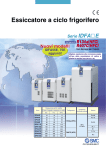
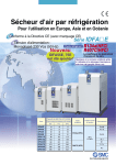
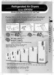
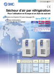
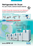
IDFAE-B.qxd
07.6.26 4:57 PM
Page 1
Refrigerated Air Dryer
For use in Europe and South East Asia
EC Directive compliant (with CE marking)
Power supply voltage:
Single-phase 230 VAC (50 Hz)
New
Series IDFA쏔E
Refrigerant R134a(HFC)
R407C(HFC)
IDFA55E, 75E
are added!
Coefficient of destruction
for ozone is zero.
Improved corrosion resistance with
the use of stainless steel, plate type
heat exchanger (IDFA4E to 75E)
Air flow capacity (m3/h [ANR])
Series
Outlet air pressure dew point
Refrigerant
Rated inlet
condition
Port size
3°C
7°C
10°C
IDFA3E
12
15
17
Rc 3/8
IDFA4E
24
31
34
Rc 1/2
IDFA6E
36
46
50
IDFA8E
65
83
91
IDFA11E
80
101
112
IDFA15E
120
152
168
IDFA22E
182
231
254
R1
IDFA37E
273
347
382
R 11/2
IDFA55E
390
432
510
IDFA75E
660
720
822
R134a (HFC)
Rc 3/4
35°C
0.7 MPa
R407C (HFC)
Rc 1
R2
CAT.ES30-9B
IDFAE-B.qxd
07.6.26 4:57 PM
Page 2
INDEX
1. Standard Products
Series IDFA
Model
Standard inlet air type
Rated inlet air temperature: 35°C
Air flow capacity (m3/h [ANR])
Rated
Outlet air pressure dew point
inlet
condition
3°C
7°C
10°C
Refrigerant
Port size
IDFA3E
12
15
17
Rc 3/8
IDFA4E
24
31
34
Rc 1/2
IDFA6E
36
46
50
IDFA8E
65
83
91
80
101
112
IDFA11E
IDFA15E
35°C
0.7 MPa
P. 3 to 5
R134a (HFC)
Rc 3/4
120
152
168
Rc 1
IDFA22E
182
231
254
R1
IDFA37E
273
347
382
IDFA55E
390
432
510
IDFA75E
660
720
822
R407C (HFC)
R 11/2
P. 6 to 8
R2
2. Options
Applicable model
Suffix
(Option symbol)
Cool compressed air output
IDFA3E to 11E
IDFA쏔E-23-A
Anti-corrosive treatment
IDFA3E to 75E
IDFA쏔E-23-C
For medium air pressure
(Auto drain bowl type: Metal bowl with level gauge)
IDFA6E to 37E
IDFA쏔E-23-K
With heavy duty auto drain
(For medium air pressure)
IDFA4E to 75E
IDFA쏔E-23-L
With circuit breaker
IDFA4E to 75E
IDFA쏔E-23-R
With terminal block for power supply, run & alarm signal and remote operation
IDFA4E to 75E
IDFA쏔E-23-T
With timer-type solenoid valve (Applicable to medium air pressure)
IDFA4E to 75E
IDFA쏔E-23-V
Specifications
3. Optional Accessories
Description
Dust-protecting filter set
Foundation bolt set
Page
P. 11
4. Data (Condensed Water Calculation, Dew Point Conversion Chart) ··· P. 12
5. Safety Instructions ··· Back page 1 to 3
1
Page
Page
P. 9
P. 10
IDFAE-B.qxd
07.6.26 4:57 PM
Page 3
Series IDFA쏔E
Model Selection
The corrected air flow capacity, which considers the user’s operating conditions, is required for selecting
the air dryer. Please select using the following procedures.
IDFA E Selection Example
1
Condition
Read the correction factor.
Obtain the correction factor A to D suitable for your operating
condition using the table below.
Data symbol
Correction factor Note)
Inlet air temperature
40°C
A
0.83
Ambient temperature
35°C
B
0.83
Inlet air pressure
0.5 MPa
C
0.92
Air consumption
31 m3/h
—
—
Note) Values obtained from the table below.
2
Calculate the corrected air flow capacity.
Corrected air flow capacity = 31 m3/h 앦 (0.83 x 0.83 x 0.92) = 48.9 m3/h
Obtain the corrected air flow capacity from the following formula.
Corrected air flow capacity = Air consumption 앦 (Correction
factor A x B x C)
3
Select the model.
According to the corrected air flow capacity of 48.9 m3/h, the IDFA8E will
be selected when the required output air pressure dew point is 3°C. The
IDFA6E will be selected when the required pressure dew point is 10°C.
Select the model which air flow capacity exceeds the
corrected air flow capacity using the specification table. (For
air flow capacity, refer to the data D below.)
4
Option
Refer to page 3, 6.
5
Finalize the model number.
Refer to page 3, 6.
6
Select accessories sold separately.
Refer to page 11.
Data A: Inlet Air Temperature
Data B: Ambient Temperature
Inlet air
Correction factor
temperature
(°C)
IDFA3E to 37E IDFA55E to 75E
1.33
1.30
5 to 25
Ambient
Correction factor
temperature
(°C)
IDFA3E to 11E IDFA15E to 75E
30
35
40
45
50
1.25
1.16
1
1
0.83
0.8
0.7
0.64
0.6
0.48
Data C: Inlet Air Pressure
Inlet air
pressure
(MPa)
0.3
0.4
0.5
0.6
0.7
0.8
0.9
1
1.2
1.4
1.6
Correction factor
20
25
30
35
40
1.1
1.1
1
1
0.91
0.97
0.83
0.89
0.79
0.77
Data D: Air Flow Capacity
IDFA3E to 11E IDFA15E to 75E
0.80
0.72
0.87
0.81
0.92
0.88
0.96
0.95
1.00
1.00
1.04
1.06
1.07
1.11
1.1
1.16
1.16
1.21
1.21
1.25
1.25
1.27
Air flow capacity (m3/h [ANR])
Model
Outlet air pressure
dew point
IDFA3E
IDFA4E
IDFA6E
IDFA8E
3°C
12
24
36
65
IDFA11E
80
7°C
15
31
46
83
101
10°C
17
34
50
91
112
Note) In case of “Option A (Cool compressed air output)”, the air flow capacity is different. Refer to page 9 for details.
Air flow capacity (m3/h [ANR])
Model
Outlet air pressure
dew point
IDFA15E
IDFA22E
IDFA37E
IDFA55E
IDFA75E
3°C
120
182
273
390
660
7°C
152
231
347
432
720
10°C
168
254
382
510
822
2
IDFAE-B.qxd
07.6.26 4:57 PM
Page 4
Refrigerant R134a (HFC)
Series IDFA쏔E
3E, 4E, 6E, 8E, 11E, 15E
(Inlet air temperature: 35°C)
How to Order
IDFA 8 E 23
Note 1)
Size
Size
3
4
6
8
11
15
Nil
A
C
K
L
R
T
V
Voltage
Symbol
Voltage
23
Single-phase
230 VAC (50 Hz)
Options and Available Combinations (Size/Option)
Symbol Note 2)
Option
Size
3
4
6
8
11
15
Nil
A
C
K
L
R
T
V
With
With timer-type
With heavy
Cool
AntiWith
For medium air pressure duty auto drain
terminal solenoid valve
None compressed corrosive Auto drain bowl type:
circuit
block for (Applicable to
(Applicable to
air output treatment Metal bowl with level gauge
breaker run & alarm medium air
medium air
signal
pressure)
pressure)
쎲
쎲
쎲
쎲
쎲
쎲
쎲
쎲
쎲
쎲
쎲
—
쎲
쎲
쎲
쎲
쎲
쎲
—
—
—
—
—
—
쎲
쎲
쎲
쎲
쎲
쎲
쎲
쎲
쎲
쎲
쎲
쎲
쎲
쎲
쎲
쎲
쎲
쎲
쎲
쎲
쎲
쎲
쎲
쎲
Note 1) G thread (PF thread) can accept the R thread (PT male thread), thus making no “F” in the thread specification setting.
A conversion adaptor for the R thread (PT male thread) is also contained.
Note 2) Enter alphabetically when multiple options are combined.
However, the following combination cannot be achieved.
• Combination of K, L and V cannot be achieved because an auto drain can only be attached to a single
option.
Note 3) Refer to page 9 for further details on optional specifications.
3
IDFAE-B.qxd
07.6.26 4:57 PM
Page 5
Refrigerated Air Dryer
Series IDFA쏔E
Standard Specifications
Standard temperature air inlet
Model
IDFA3E IDFA4E IDFA6E IDFA8E IDFA11E IDFA15E
Operating range
Specifications
Fluid
Compressed air
Inlet air temperature
Inlet air pressure
Ambient temperature (Humidity)
Electric
Rated specifications Note 3)
Note 1)
Air flow
capacity
m3/h
Standard
condition
(ANR)
Note 2)
Compressor
intake
condition
(°C)
5 to 50
(MPa)
0.15 to 1.0
(°C)
2 to 40 (Relative humidity of 85% or less)
Outlet air pressure dew point (3°C)
12
24
36
65
80
120
Outlet air pressure dew point (7°C)
15
31
46
83
101
152
Outlet air pressure dew point (10°C)
17
34
50
91
112
168
Outlet air pressure dew point (3°C)
13
25
37
68
83
125
Outlet air pressure dew point (7°C)
16
32
48
86
105
158
Outlet air pressure dew point (10°C)
18
35
52
95
116
175
Inlet air pressure
(MPa)
0.7
Inlet air temperature
(°C)
35
Ambient temperature
(°C)
25
(W)
Single-phase: 230 VAC [Voltage fluctuation ±10%] 50 Hz
180
208
385
470
Power supply voltage
Power consumption
Operating current
1.2
(A)
Applicable circuit breaker capacity Note 4) (A)
Condenser
Auto drain
Port size
Rc 3/8
Rc 1/2
18
22
Accessory
Weight
(kg)
10
Float type
(Normally open)
Rc 3/4
Hexagon nipple
23
JIS Symbol
27
Rc 1
28
46
Body panel: White 1
Base: Gray 2
Coating color
Auto drain
3.0
R134a (HFC)
Float type
(Normally closed)
EC Directive (with CE marking)
Compliant standards
Note 1)
Note 2)
Note 3)
Note 4)
Note 5)
2.7
Air-cooled
Refrigerant
Refrigerated
air dryer
1.4
5
Air flow capacity under the standard condition (ANR) [atmospheric pressure at 20°C, relative humidity at 65%]
Air flow capacity converted by the compressor intake condition [atmospheric pressure at 32°C]
Select air dryer according to the model selection method (page 2) for the models beyond the rated specifications.
Install a circuit breaker with a sensitivity of 30 mA.
When a short-term interruption of the power supply (including momentary interruption) occurs in this equipment, the
restarting of normal operations may require some time or may be impossible due to the operation of protective devices even
after the supply of power returns.
Replacement Parts
Model
IDFA3E IDFA4E IDFA6E IDFA8E IDFA11E IDFA15E
Auto drain replacement parts no. Note 5)
AD38
AD48
Note 6) The part number for the auto drain components without including the body part.
Body part replacement is impossible.
Body
Auto drain
Construction (Air/Refrigerant Circuit)
Humid, hot air coming into
the air dryer will be cooled
down by a cooler re-heater
(heat exchanger). Water
condensed at this time will
be removed from the air by
auto drain and drained out
automatically. Air separated from the water will be
heated by a cooler re-heater (heat exchanger) to obtain the dried air, which
goes through to the outlet
side.
IDFA3E
Drain separator
Compressed air inlet
Cooler
Compressed air outlet
Drain outlet
Re-heater
Volume
control valve
IDFA4E, IDFA6E
IDFA8E, IDFA11E, IDFA15E
Compressed
air inlet
Compressed
air outlet
Evaporation
thermometer
Heat exchanger
Drain separator
Volume control valve
Drain outlet
Capillary tube
Condenser
Fan motor
Pressure switch
Capillary tube
Compressor for
refrigeration
Compressor for
refrigeration
Condenser
Pressure switch
Fan motor
Evaporation thermometer
4
IDFAE-B.qxd
07.6.26 4:57 PM
Page 6
Series IDFA쏔E
Dimensions
IDFA3E to 15E
A
B
A
E
D
F
C
G
C
Q
M
N
L
P
In case of IDFA3E
K
IDFA4E to 15E
4 x ø13
Dimensions
(mm)
Model
Port size
A
B
C
D
E
F
G
K∗
L∗
M∗
N∗
IDFA3E
IDFA4E
IDFA6E
IDFA8E
IDFA11E
IDFA15E
Rc 3/8
226
410
473
67
125
304
33
36
154
21
330
Rc 1/2
Rc 3/4
Rc 1
453
270
300
455
498
31
485
568
603
578
∗ Meaning the foot dimensions for the IDFA3E.
5
275
283
42
80
355
41
54
396
87
15
240
80
P
13
—
15
300
43
101
380
Q
15
314
16
IDFAE-B.qxd
07.6.26 4:57 PM
Page 7
Refrigerant R407C (HFC)
Series IDFA쏔E
22E, 37E, 55E, 75E
(Inlet air temperature: 35°C)
How to Order
IDFA 55 E 23
Note 1)
Size
Size
22
37
55
75
Nil
A
C
K
L
R
T
V
Voltage
Symbol
Voltage
23
Single-phase
230 VAC (50 Hz)
Options and Available Combinations (Size/Option)
Symbol Note 2)
Option
Size
22
37
55
75
Nil
A
C
K
L
R
T
V
With
With timer-type
With heavy
Cool
AntiWith
For medium air pressure duty auto drain
terminal solenoid valve
None compressed corrosive Auto drain bowl type:
circuit
block for (Applicable to
(Applicable to
air output treatment Metal bowl with level gauge
breaker run & alarm medium air
medium air
pressure)
signal
pressure)
쎲
쎲
쎲
쎲
—
—
—
—
쎲
쎲
쎲
쎲
쎲
쎲
—
—
쎲
쎲
쎲
쎲
쎲
쎲
쎲
쎲
쎲
쎲
쎲
쎲
쎲
쎲
쎲
쎲
Note 1) G thread (PF thread) can accept the R thread (PT male thread), thus making no “F” in the thread specification setting.
Note 2) Enter alphabetically when multiple options are combined.
However, the following combination cannot be achieved.
• Combination of K, L and V cannot be achieved because an auto drain can only be attached to a single
option.
Note 3) Refer to page 9 for further details on optional specifications.
6
IDFAE-B.qxd
07.6.26 4:57 PM
Page 8
Series IDFA쏔E
Standard Specifications
Standard temperature air inlet
Model
IDFA22E IDFA37E IDFA55E IDFA75E
Operating range
Specifications
Fluid
Compressed air
Inlet air pressure
Rated specifications Note 3)
5 to 50
(MPa)
0.15 to 1.0
(°C)
Ambient temperature (Humidity)
Note 1)
Electric
(°C)
Inlet air temperature
Air flow
capacity
m3/h
Standard
condition
(ANR)
Note 2)
Compressor
intake
condition
2 to 40 (Relative humidity of 85% or less)
Outlet air pressure dew point (3°C)
182
273
390
660
Outlet air pressure dew point (7°C)
231
347
432
720
Outlet air pressure dew point (10°C)
254
382
510
822
Outlet air pressure dew point (3°C)
189
284
405
686
Outlet air pressure dew point (7°C)
240
361
449
748
Outlet air pressure dew point (10°C)
264
397
530
854
Inlet air pressure
(MPa)
0.7
Inlet air temperature
(°C)
35
Ambient temperature
(°C)
25
Power supply voltage
Single-phase: 230 VAC [Voltage fluctuation ±10%] 50 Hz
760
1130
1700
(W)
4.3
5.4
7.9
(A)
Power consumption
Operating current
Applicable circuit breaker capacity Note 4)
Air-cooled
Refrigerant
R407C (HFC)
Auto drain
Float type
(Normally open)
R 11/2
R1
Port size
R2
—
Accessory
Weight
54
(kg)
62
JIS Symbol
100
EC Directive (with CE marking)
Compliant standards
Note 1) Air flow capacity under the standard condition (ANR) [atmospheric pressure at 20°C, relative humidity at
65%]
Note 2) Air flow capacity converted by the compressor intake condition [atmospheric pressure at 32°C]
Note 3) Select air dryer according to the model selection method (page 2) for the models beyond the rated
specifications.
Note 4) Install a circuit breaker with a sensitivity of 30 mA.
Note 5) When a short-term interruption of the power supply (including momentary interruption) occurs in this
equipment, the restarting of normal operations may require some time or may be impossible due to the
operation of protective devices even after the supply of power returns.
Auto drain
Replacement Parts
Model
IDFA22E IDFA37E IDFA55E IDFA75E
Auto drain replacement parts no. Note 5)
AD48
Note 6) The part number for the auto drain components without including the body part.
Body part replacement is impossible.
Body
Auto drain
Construction (Air/Refrigerant Circuit)
Humid, hot air coming into
the air dryer will be cooled
down by a cooler re-heater
(heat exchanger). Water
condensed at this time will
be removed from the air by
auto drain and drained out
automatically. Air separated from the water will be
heated by a cooler re-heater (heat exchanger) to obtain the dried air, which
goes through to the outlet
side.
IDFA22E, IDFA37E, IDFA55E, IDFA75E
Compressed air inlet
Compressed air outlet
Evaporation
thermometer
Cooler re-heater
(Heat exchanger)
Auto drain
Ball valve
Volume control valve
Accumulator
(IDFA22E, 37E, 55E only)
Drain outlet
Condenser
Capillary tube
Pressure switch
Compressor for refrigeration
Fan motor
High pressure switch
(IDFA55E, 75E only)
7
116
Body panel: White 1
Base: Gray 2
Coating color
Refrigerated
air dryer
20
10
(A)
Condenser
IDFAE-B.qxd
07.6.26 4:57 PM
Page 9
Refrigerated Air Dryer
Series IDFA쏔E
Dimensions
IDFA22E, IDFA37E
D
B
G
A
F
C
E
M
N
L
P
K
4 x ø13
Dimensions
(mm)
Model
Port size
IDFA22E
IDFA37E
R1
A
290
R 11/2
B
C
775
623
855
D
134
E
405
F
698
G
K
93
13
L
25
M
85
N
600
680
P
Q
340
—
IDFA55E, IDFA75E
B
R
A
Q
E
D
C
F
G
M
N
L
P
K
4 x ø13
Dimensions
Model
IDFA55E
IDFA75E
(mm)
Port size
R2
A
470
B
855
C
800
900
D
E
(128) (273)
F
(868)
(968)
G
K
L
M
N
P
Q
R
(110)
13
500
75
700
526
(110)
519
8
IDFAE-B.qxd
07.6.26 4:57 PM
Page 10
Series IDFA쏔E
Options 1
A
For “How to Order” optional
models, refer to page 3 and 6.
Option symbol
Cool compressed air output
IDFA3E to 11E
There is no heating of cooled, dehumidified air as it leaves the air dryer.
The air flow capacity with this option is smaller than that of the standard
dryer. (The external dimensions are identical with the standard product.)
Note) Perform thermal insulation treatment for piping and equipment
installed after the dryer to prevent the formation of condensation.
Air Flow Capacity
IDFA3E IDFA4E IDFA6E IDFA8E IDFA11E
Model
Air flow capacity m3/h (ANR)
18
23
29
32
L
Option symbol
With heavy duty auto drain
(Applicable to medium air pressure)
Dimensions
The float type auto drain used in the
standard air dryer is replaced with a
heavy duty auto drain (ADH4000-04)
which enables the drainage to discharge more efficiently.
IDFA4E to 15E
39
Conditions: Inlet air pressure: 0.7 MPa, Inlet air temperature: 35°C ,
Outlet air temperature: 10°C Ambient temperature: 25°C
IDFA4E to 75E
(mm)
Model
A
IDFA4E
IDFA6E
IDFA8E, 11E
IDFA15E
55
67
139
47
(207)
(157)
Option symbol
Anti-corrosive treatment
IDFA all models
This minimizes the corrosion of the copper and copper alloy parts when
the air dryer is used in an atmosphere containing hydrogen sulfide or sulfurous acid gas. (Corrosion cannot be completely prevented.)
Special epoxy coating: Copper tube and copper alloy parts.
The coating is not applied on the heat exchanger or around electrical
parts, where operation may be affected by the coating.
Ball valve
(A)
C
Drain outlet
Rc 1/2
Heavy duty
auto drain
∗ Corrosion is not covered under warranty.
K
IDFA22E to 75E
Option symbol
For medium air pressure
Auto drain bowl type:
Metal bowl with level gauge
IDFA6E to 37E
The auto drain is changed from the standard one to one with a medium
pressure specification.
A metal bowl with a level gauge which can confirm the water level is used
for the auto drain.
Ball valve
Drain tube:
Length approx.
0.95 m
(O.D. ø10)
A
Specifications
1. Maximum operating pressure: 1.6 MPa
2. Dimensions ··· same as standard products
Heavy duty
auto drain
Dimensions
Replacement Parts
Model
Auto drain
assembly part no.
IDFA22E, 37E Approx. 100
IDFA55E, 75E Approx. 50
Note
IDFA6E to 15E
IDF-S0086
The AD48-8-X2110 auto drain,
insulator, and one-touch fitting
are included.
IDFA22E, 37E
AD48-8-X2110
Single auto drain unit
(mm)
A
Model
Note 1) The heavy duty auto drain and the ball valve are both enclosed in the same
shipping package as the main body of the air dryer. Customers are required
to mount the parts to the air dryer. (Except IDFA22E to 75E)
Note 2) Customers will need to supply the fitting and tubing for the drain piping.
(Except IDFA22E to 75E)
Replacement Parts: Heavy Duty Auto Drain
Model
IDFA4E to 15E
Replacement parts no.
(Description)
ADH4000-04
(Heavy duty auto drain)
Configuration
Heavy duty
auto drain
Replacement
kit for exhaust
mechanism
IDFA22E to 75E
9
ADH-E400
(Replacement kit for
exhaust mechanism)
Housing
(You don’t need
to purchase a
new housing.)
IDFAE-B.qxd
07.6.26 4:57 PM
Page 11
Series IDFA쏔E
Options 2
R
For “How to Order” optional
models, refer to page 3 and 6.
Option symbol
With circuit breaker
IDFA4E to 75E
T
A circuit breaker with cover is attached to the side of the air dryer. This
saves additional electrical wiring at the time of installation.
IDFA4E to 15E
60
C
A
Circuit breaker
IDFA4E to 75E
Note) Please be sure to confirm the electric circuits with the drawings or instruction
manual before using the output signal.
B
E
With terminal block for
power supply, run & alarm
signal and remote operation
In addition to the terminals for the power supply, terminals for the
operating signal and the error signal are also available. (No-voltage
contact)
Also, in the case of remote control, operate it from the power supply side
while the air dryer switch remains ON.
Contact capacity:
230 VAC, 4 A 24 VDC, 5 A for operating and
error signals.
Minimum current value: 20 V, 5 mA (AC/DC) for operating and error
signals.
40
D
Option symbol
Power cable outlet (ø17)
Grommet with membrane
Dimensions
IDFA4E to 15E
(mm)
A
B
C
D
E
IDFA4E, 6E, 8E, 11E
IDFA15E
32
43
230
97
34
15
258
102
82
—
Signal cable outlet (ø17)
Grommet with membrane
Terminal block
C
Model
A
D
B
IDFA22E to 75E
Power cable outlet (ø17)
Grommet with membrane
Dimensions
Circuit breaker
E
Power cable outlet (ø17)
(Wire diameter ø9 to 11)
IDFA4E, 6E, 8E, 11E
IDFA15E
32
230
67
179
43
258
77
158
Signal cable outlet
(Wire diameter ø17)
Grommet with
membrane
(mm)
125
B
C
59
39
148
81
133
73
D
E
E
40
25
46
60
50
36
Terminal
block
C
A
60
Model
IDFA4E-23, IDFA6E-23
IDFA8E-23, IDFA11E-23
230 V type
D
F
Breaker Capacity and Sensitivity Current
Voltage
C
IDFA15E-23, IDFA22E-23
IDFA37E-23, IDFA55E-23
IDFA75E-23
Power cable outlet (ø17)
(Wire diameter ø9 to 11)
B
D
A
IDFA22E
IDFA37E
IDFA55E
IDFA75E
B
IDFA22E to 75E
Dimensions
Model
A
D
A C
B
(mm)
Model
Dimensions
Breaker
capacity
Sensitivity
current
5A
10 A
20 A
(mm)
Model
A
B
C
D
IDFA22E, 37E
IDFA55E, 75E
25
46
135
81
50
36
207
81
30 mA
V
Option symbol
With timer-type solenoid valve
(Applicable to medium air pressure)
IDFA4E to 75E
Drainage is discharged by controlling a solenoid valve with a timer.
A strainer for solenoid valve protection and stop valve are also included.
Maximum operating pressure: 1.6 MPa
∗ The timer-type solenoid valve actuates once (for 0.5 s) every 30 s.
Replacement Parts
Model
Part no.
Note
IDFA4E to 75E
IDF-S0198
230 VAC
10
IDFAE-B.qxd
07.6.26 4:57 PM
Page 12
Optional Accessories
Dust-protecting
filter set
Foundation
bolt set
Features
Specifications
Applicable dryer
Prevents a decline in the performance
of the air dryer, even in a dusty
atmosphere.
Max. ambient
temperature
40°C
IDFA3E to 75E
Bolts for fixing the air dryer to the
foundations.
Easy to secure by striking its axle.
Stainless steel
IDFA4E to 75E
How to Order
Dust-protecting filter set
IDF
Foundation bolt set
FL 209
IDF
AB 500
Applicable dryer
Applicable dryer
Symbol Applicable dryer
IDFA4E to 75E
500
Symbol Applicable dryer
IDFA3E
209
202
203
204
205
206
207
208
213
214
IDFA4E
IDFA6E
IDFA8E
IDFA11E
IDFA15E
IDFA22E
IDFA37E
IDFA55E
IDFA75E
Dust-protecting Filter Set / Dimensions
Dimensions
A
(20)
(10)
B
(20)
Part no.
(IDF-FL209)
(IDF-FL202 to 208, 213, 214)
Foundation Bolt Set / Dimensions
Dimensions
(mm)
(mm)
Applicable dryer
IDF-AB500
IDFA4E to 75E
50
Part no.
Mounting hole diameter: ø10.5
11
Nominal
thread size
M10
Material
Stainless steel
Pcs. of
1 set
4
IDF-FL209
IDF-FL202
IDF-FL203
IDF-FL204
IDF-FL205
IDF-FL206
IDF-FL207
IDF-FL208
IDF-FL213
IDF-FL214
Applicable dryer
IDFA3E
IDFA4E
IDFA6E
IDFA8E
IDFA11E
IDFA15E
IDFA22E
IDFA37E
IDFA55E
IDFA75E
(mm)
A
B
220
310
375
340
375
310
420
550
720
610
240
195
265
270
315
365
400
560
Weight (g)
35
45
55
70
75
70
100
140
175
190
IDFAE-B.qxd
07.6.26 4:57 PM
Page 13
Data
0.7
0.8
0.3
0.4
0.5
0.6
30
25
1.0
Amount of condensed water
C–H
20 18.2 - 3.0 = 15.2 g/m3
C
D
1.
1. 4
6
20%
B
35
0.2
Amount of water in air (g /m3)
40%
60%
Relat
ive h
um
idity
100%
80 %
40
0.1 M
45
Pa
Atmos
pheric
pressu
re
Condensed Water Calculation
15
10
5
G
H
–20
–10
0
10
20
0
A
30
40
50
60
0
Ambient temperature (Air compressor intake air temperature) (°C)
Dew Point Conversion Chart
60
50
40
30
Pressure dew point (°C)
20
10
B
A
1.5 MPa
1.3 MPa
1.1 MPa
0.9 MPa
0.7 MPa
0.5 MPa
0.3 MPa
0.1 MPa
Atmospheric
pressure
0
–10
–20
–30
–40
–50
C
–60
–60
–50
–40
–30
–20
–10
0
10
20
30
Atmospheric pressure dew point (°C)
How to read the dew point conversion chart
Example) To obtain the atmospheric dew point at a pressure dew point of
10°C, and a pressure of 0.7 MPa.
1. Trace the arrow mark from point A at a pressure dew point of 10°C
to obtain the intersection B on the pressure characteristic line for
0.7 MPa.
2. Trace the arrow mark from point B to obtain the intersection C on
the atmospheric pressure dew point.
3. The intersection C is the conversion value –17°C under atmospheric pressure dew point.
10
F
20
E
30
40
50
60
70
80
Pressure dew point (°C)
How to calculate the amount of condensed water
Example) To obtain the amount of condensed water
when the inlet air of a compressor is pressurized to 0.7 MPa then cooled down to 25°C.
Given an ambient temperature of 30°C and a
relative humidity of 60%.
1. Trace the arrow mark from point A of ambient temperature 30°C to obtain the intersection B on the
curved line for the relative humidity of 60%.
2. Trace the arrow mark from the intersection B to
obtain the intersection D on the curved line for the
0.7 MPa pressure characteristics.
3. Trace the intersection D to obtain the intersection
E.
4. The intersection E is the pressure dew point at 0.7
MPa with an ambient temperature of 30°C and a
relative humidity of 60%. The value for E is at
62°C.
5. Trace the intersection E upward to D and leftward
to obtain the intersection C on the vertical line.
6. The intersection C is the amount of water which is
included in the compressed air 1 m3 at 0.7 MPa, a
pressure dew point of 62°C. The amount of water
is 18.2 g/m3.
7. Trace the arrow mark from F (cooling temperature
25°C (pressure dew point 25°C)) to obtain the intersection G on the pressure characteristic line for
0.7 MPa.
8. From the intersection G, trace the arrow mark to
obtain the intersection H on the vertical line.
9. The intersection H is the amount of water which is
included in the compressed air 1 m3 at 0.7 MPa,
pressure dew point of 25°C. The amount of water
is 3.0 g/m3.
10. Therefore, the amount of condensed water is as
following. (per 1 m3)
The amount of water at the intersection C
– the amount of water at the intersection H
= the amount of condensed water
18.2 – 3.0 = 15.2 g/m3
12
IDFAE-B.qxd
07.6.26 4:57 PM
Page 14
Series IDFA쏔E
Safety Instructions
These safety instructions are intended to prevent a hazardous situation and/or equipment damage. These
instructions indicate the level of potential hazard by labels of "Caution", "Warning" or "Danger". To
ensure safety, be sure to observe ISO 4414 Note 1), JIS B 8370 Note 2) and other safety practices.
쐽Explanation of the Labels
Labels
Danger
Warning
Caution
Note 1)
Note 2)
Note 3)
Note 4)
Explanation of the labels
In extreme conditions, there is a possible result of serious injury or loss of life.
Operator error could result in serious injury or loss of life.
Operator error could result in injury Note 3) or equipment damage. Note 4)
ISO 4414: Pneumatic fluid power – General rules relating to systems
JIS B 8370: General Rules for Pneumatic Equipment
Injury indicates light wounds, burns and electrical shocks that do not require hospitalization or hospital visits for long-term medical treatment.
Equipment damage refers to extensive damage to the equipment and surrounding devices.
쐽Selection/Handling/Applications
1. The compatibility of the pneumatic equipment is the responsibility of the person who designs the
pneumatic system or decides its specifications.
Since the products specified here are used in various operating conditions, their compatibility for the specific pneumatic system
must be based on specifications or post analysis and/or tests to meet the specific requirements. The expected performance and
safety assurance are the responsibility of the person who has determined the compatibility of the system. This person should
continuously review the suitability of all items specified, referring to the latest catalog information with a view to giving due
consideration to any possibility of equipment failure when configuring a system.
2. Only trained personnel should operate pneumatically operated machinery and equipment.
Compressed air can be dangerous if handled incorrectly. Assembly, handling or repair of the systems using pneumatic equipment
should be performed by trained and experienced operators. (Understanding JIS B 8370 General Rules for Pneumatic Equipment,
and other safety rules are included.)
3. Do not service machinery/equipment or attempt to remove components until safety is confirmed.
1. Inspection and maintenance of machinery/equipment should only be performed once measures to prevent falling or runaway
of the driven objects have been confirmed.
2. When equipment is removed, confirm the safety process as mentioned above. Turn off the supply pressure for this equipment
and exhaust all residual compressed air in the system, and release all the energy (liquid pressure, spring, condenser, gravity).
3. Before machinery/equipment is restarted, take measures to prevent quick extension of a cylinder piston rod, etc.
4. If the equipment will be used in the following conditions or environment, please contact SMC first and
be sure to take all necessary safety precautions.
1. Conditions and environments beyond the given specifications, or if product is used outdoors.
2. Installation on equipment in conjunction with atomic energy, railway, air navigation, vehicles, medical equipment, food and
beverages, recreation equipment, emergency stop circuits, clutch and brake circuits in press applications, or safety equipment.
3. An application which has the possibility of having negative effects on people, property, requiring special safety analysis.
4. If the products are used in an interlock circuit, prepare a double interlock style circuit with a mechanical protection function for
the prevention of a breakdown. And, examine the devices periodically if they function normally or not.
쐽Exemption from Liability
1. SMC, its officers and employees shall be exempted from liability for any loss or damage arising out of
earthquakes or fire, action by a third person, accidents, customer error with or without intention, product misuse, and any other damages caused by abnormal operating conditions.
2. SMC, its officers and employees shall be exempted from liability for any direct or indirect loss or damage, including consequential loss or damage, loss of profits, or loss of chance, claims, demands, proceedings, costs, expenses, awards, judgments and any other liability whatsoever including legal costs
and expenses, which may be suffered or incurred, whether in tort (including negligence), contract,
breach of statutory duty, equity or otherwise.
3. SMC is exempted from liability for any damages caused by operations not contained in the catalogs
and/or instruction manuals, and operations outside of the specification range.
4. SMC is exempted from liability for any loss or damage whatsoever caused by malfunctions of its products when combined with other devices or software.
Back page 1
IDFAE-B.qxd
07.6.26 4:57 PM
Page 15
Series IDFA쏔E
Specific Product Precautions 1
Be sure to read this before handling. For Air Preparation Equipment Precautions,
refer to “Precautions for Handling Pneumatic Devices” (M-03-E3A).
Installation
Air Piping
• Avoid locations where the air dryer will be in direct contact with
wind and rain. (Places where relative humidity is greater than
85%)
• Avoid exposure to direct sunlight.
• Avoid locations that contain much dust, corrosive gases, or
flammable gases. Failure due to corrosion is not covered under
warranty. However, when the risk of corrosion is high, select
“Option C” (copper tubing with anti-corrosive treatment).
• Avoid locations of poor ventilation and high temperature.
• Too close to a wall etc. Leave sufficient room between the dryer
and the wall according to the “Maintenance space” in the operation manual.
• Avoid locations where a dryer could draw in high temperature
air that is discharged from an air compressor or other dryer.
• Be careful to avoid an error in connecting the air piping at the
compressed air inlet (IN) and outlet (OUT).
• Install by-pass piping since it is needed for maintenance.
Caution
Caution
IDFA3E
Compressed air inlet
Compressed air outlet
Valve closed
Valve open
IDFA4E to 15E
Compressed air inlet
Valve closed
The air exhaust should not flow into the neighboring equipment. (Top side)
• Avoid locations subjected to vibration.
• Avoid possible locations where the drain can freeze.
• Use the air dryer with an ambient temperature lower than 40°C.
• Avoid installation on machines for transporting, such as trucks,
ships, etc.
Drain Tube
Compressed air outlet
Valve open
IDFA22E, 37E
Compressed air outlet
Compressed air inlet
Valve closed
Caution
• A polyurethane tube is attached as a drain tube for the IDFA3E
to 37E. Use this tube to discharge drainage.
• Do not use the drain tube in an upward direction. Do not bend or
crush the drain tube. (Operation of the auto drain will stop water
vapor from discharging through the air outlet.)
Valve
open
Power Supply
Caution
• Connect the power supply to the terminal block.
• Install a suitable circuit breaker applicable for the specific model.
• The voltage fluctuation should be maintained within ±10% of the
rated voltage.
Back page 2
IDFAE-B.qxd
07.6.26 4:57 PM
Page 16
Series IDFA쏔E
Specific Product Precautions 2
Be sure to read this before handling. For Air Preparation Equipment Precautions,
refer to “Precautions for Handling Pneumatic Devices” (M-03-E3A).
Air Piping
Auto Drain
Caution
IDFA55E, 75E
Caution
Compressed air outlet
Compressed air inlet
The auto drain may not function properly, depending on the
quality of the compressed air. Check the operation once a day.
Valve closed
Valve
open
Cleaning of Ventilation Area
Caution
Remove dust from the ventilation area once a month using a vacuum cleaner or an air blow nozzle.
Time Delay for Restarting
Caution
• When tightening piping at the air inlet/outlet tube, the hexagonal
parts of the port on the air dryer side or piping should be held
firmly with a spanner or adjustable angle wrench.
• Variations in operating conditions may cause condensation to
form at the surface of the outlet piping. Apply thermal insulation
around the piping to prevent condensation from forming.
• Vibration resulting from the compressor should not be transmitted through air piping to the air dryer.
• Do not allow the weight of the piping to lie directly on the air dryer.
Protection Circuit
Caution
When the air dryer is operated under the following stated conditions, a protection circuit is activated, the light turns off and operation stops.
• When the compressed air temperature is too high.
• When the compressed air flow rate is too high.
• When the ambient temperature is too high. (40°C or higher)
• When the fluctuation of the power supply is beyond the rated
voltage ±10%.
• When the dryer is drawing in high temperature air that is discharged from an air compressor or other dryer.
• The ventilation port is obstructed by a wall or clogged with dust.
Compressor Air Delivery
Caution
Use an air compressor with an air delivery of 100 l/min or
larger with the IDFA3E to 75E series.
Since the auto drain of the IDFA3E to 75E is designed in such a
way that the valve remains open unless the air pressure rises to
0.15 MPa or higher, air will blow out from the drain discharge port
at the time of air compressor start-up until the pressure increases. Therefore, if an air compressor has a small air delivery, the
pressure may not be sufficient.
Back page 3
Allow at least three minutes before restarting the dryer. If the air
dryer is restarted within three minutes after being stopped, the
protection circuit will be activated, operating light turns off and the
dryer will not be activated.
IDFAE-B.qxd
07.6.26 4:57 PM
Page 17
Air Dryers for Japan Use
Complies with CFC restrictions
Refrigerated Air Dryer
Series IDF
Standard temperature air inlet type
Rated inlet air temperature:
35, 40°C
Model
Rated
Air flow capacity (m3/min [ANR])
inlet
50 Hz
60 Hz
condition
Applicable air
compressor (kW)
Refrigerant
Port size
0.1
0.12
0.75
IDF2E
0.2
0.235
1.5
IDF3E
0.32
0.37
2.2
IDF4E
0.52
0.57
3.7
IDF6E
0.75
0.82
5.5
1.22
1.32
7.5
IDF11E
1.65
1.82
11
IDF15E
2.8
3.1
15
IDF22E
3.9
4.3
22
R1
IDF37E
5.7
6.1
37
R 11/2
IDF1E
IDF8E
Rc 3/8
R134a (HFC)
35°C
0.7 MPa
IDF55E
8.4
9.8
55
IDF75E
11.0
12.4
75
IDF120D
40°C
0.7
MPa
IDF150D
20.0
23.0
120
25.0
30.0
150
IDF190D
32.0
38.0
190
IDF240D
43.0
50.0
240
54.0
65.0
370
Rc 1/2
Rc 3/4
Rc 1
R2
R407C (HFC)
35°C
IDF370B 0.7 MPa
Complies with CFC restrictions
2 1/2 B flange
3B flange
4B flange
R22
Refrigerated Air Dryer
6B flange
Series IDU
High temperature air inlet type
Rated inlet air temperature:
50, 55°C
Model
Rated
Air flow capacity (m3/min [ANR])
inlet
50 Hz
60 Hz
condition
Applicable air
compressor (kW)
Refrigerant
Port size
IDU3E
0.32
0.37
2.2
Rc 3/8
IDU4E
0.52
0.57
3.7
Rc 1/2
IDU6E
0.75
0.82
5.5
1.1
1.2
7.5
1.5
1.7
11
IDU15E
2.6
2.8
15
IDU22E
3.9
4.3
22
IDU37E
5.7
6.1
37
9.0
55
12.4
75
IDU8E
IDU11E
IDU55C
IDU75C
55°C
0.7 MPa
50°C
0.7 MPa
7.65
10.5
R134a (HFC)
Rc 3/4
Rc 1
R407C (HFC)
R22
R1
R 1 1 /2
R2
∗ See separate catalog.
Back page 4
IDFAE-B.qxd
07.6.26 4:57 PM
Page 18
Air Dryers Compliant to
Overseas Standards
Refrigerated Air Dryer
Series IDFB쏔E
For use in North, Central & South America
UL certified
Refrigerant: R134a (HFC)
Coefficient of destruction for
ozone is zero.
Improved corrosion resistance
with the use of stainless steel,
plate type heat exchanger
Power supply voltage:
Single-phase 115 VAC (60 Hz)
230 VAC (60 Hz)
(IDFB4E to 37E)
Air flow capacity SCFM (m3/h [ANR])
Series
Refrigerant
Outlet air pressure dew point
Rated inlet
condition
Port size
37°F (2.8°C)
45°F (7.2°C)
50°F (10°C)
IDFB3E
10 (17)
11 (19)
12 (20)
NPT 3/8
IDFB4E
15 (25)
16 (27)
17 (28)
NPT 1/2
IDFB6E
25 (43)
26 (45)
28 (47)
IDFB8E
41 (70)
43 (74)
45 (77)
IDFB11E
59 (100)
62 (106)
65 (110)
IDFB15E
71 (120)
80 (136)
86 (147)
IDFB22E
107 (182)
120 (205)
130 (221)
IDFB37E
161 (273)
173 (294)
181 (308)
R134a (HFC)
100°F
(37.8°C)
NPT 3/4
100 psig
(0.7 MPa)
NPT 1
NPT 11/2
∗ See separate catalog for dryer models conforming with North American standards (UL).
Back page 5
IDFAE-B.qxd
07.6.26 4:57 PM
Page 19
Related Products
Membrane Air Dryer
Series IDG
Dew point indicator for checking
air drying condition at a glance
CFC free:
Environmentally friendly
(Except IDG1)
(The IDG3, IDG5, IDG3H, IDG5H are semistandard.)
No need for a power supply
A power supply is not necessary at all.
Saves time and effort for wiring, and
there is no need to consider electrical
standards.
• Compact
• Lightweight
• Space-saving
No vibration nor heat
discharge
No mechanically moving parts such as
refrigerator
Fitting for discharging
purge air available
Purge air can be discharged with a tube
if it should not be discharged around the
membrane air dryer (semi-standard).
Suitable for a low dew point
Outlet air atmospheric
pressure dew point: –40˚C
IDG30L, IDG50L, IDG60L
IDG75L, IDG100L
Outlet air atmospheric
pressure dew point: –60˚C
IDG60S, IDG75S, IDG100S
Discharged air noise reduced
with built-in silencer
Except IDG1, IDG3, IDG3H, IDG5,
IDG5H, IDG30, IDG30H, IDG30L,
IDG50, IDG50H, IDG50L
Outlet air flow rate
10 to 1000 l/min (ANR)
Heatless Air Dryer
Heatless type ID series is
ideal for applications that
require dry air with a low
dew point.
Supplies dry air with a low
dew condensation point of
–30°C or less.
Series ID
Possible to check outlet
dew point with indicator
(Self-regenerative style allows easy
maintenance.)
Outlet air flow rate
80 to 780 l/min (ANR)
Small and light without
heater and electric control panel
Back page 6
IDFAE-B.qxd
07.6.26 4:57 PM
Page 20
Record of changes
B edition ∗ Addition of Refrigerated Air Dryer, IDFA55E, 75E.
∗ Options on page 3 and 6: Addition of “with timer-type
solenoid valve”.
∗ Number of pages 16 to 20.
LT
Safety Instructions Be sure to read “Precautions for Handling Pneumatic Devices” (M-03-E3A) before using.
Akihabara UDX 15F,
4-14-1, Sotokanda, Chiyoda-ku, Tokyo 101-0021, JAPAN
Phone: 03-5207-8249 FAX: 03-5298-5362
URL http://www.smcworld.com
© 2007 SMC Corporation All Rights Reserved
Specifications are subject to change without prior notice
and any obligation on the part of the manufacturer.
D-DN
1st printing KX printing LT 13500DN Printed in Japan.
This catalog is printed on recycled paper with concern for the global environment.