1
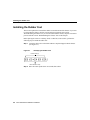
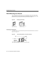
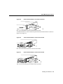
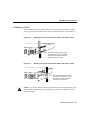
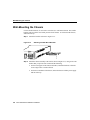
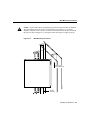
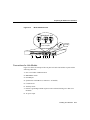
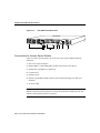
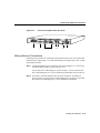
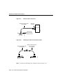
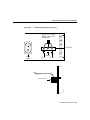
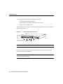
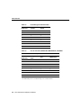
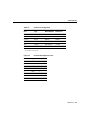
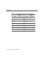
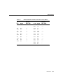
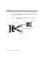
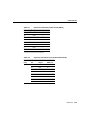
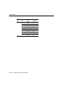
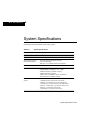
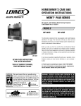
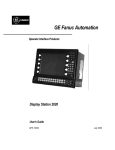
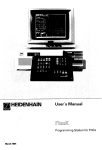
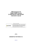
1
CHAPT E R
Getting Started
This chapter contains information about safety, system specifications, inspecting the
system, preventing electrostatic discharge (ESD) damage, and required tools and parts. For
international regulatory compliance information, refer to the appendix “Regulatory
Compliance.”
If you plan to place the router on a desk or table, do not place anything on top of
the router that weighs in excess of 10 pounds (4.5 kg). Excessive weight on top could
damage the chassis.
Caution
Safety Recommendations
Follow these guidelines to ensure general safety:
•
•
•
•
Keep the work area clear and dust-free during and after installation.
•
Wear safety glasses when working under any conditions that might be hazardous to your
eyes.
•
Do not perform any action that creates a potential hazard to people or makes the
equipment unsafe.
Put the removed chassis cover in a safe place.
Keep tools away from walk areas where you and others could fall over them.
Do not wear loose clothing that could get caught in the chassis. Fasten your tie or scarf
and roll up your sleeves.
Getting Started 1-1
Safety Recommendations
Warning Before working on equipment that is connected to power lines, remove jewelry
(including rings, necklaces, and watches). Metal objects will heat up when connected to
power and ground and can cause serious burns or weld the metal object to the terminals.
•
Locate the emergency power-off switch for the room in which you are working. Then,
if an electrical accident occurs, you can act quickly to shut off power.
•
•
Before working on the system, turn off the power and unplug the power cord.
Disconnect all power before doing the following:
— Installing or removing a chassis
— Working near power supplies
— Performing a software upgrade
•
•
•
Do not work alone if potentially hazardous conditions exist.
•
If an electrical accident occurs, proceed as follows:
Never assume that power is disconnected from a circuit. Always check.
Look carefully for possible hazards in your work area, such as moist floors, ungrounded
power extension cables, and missing safety grounds.
— Use caution; do not become a victim yourself. Turn off power to the system.
— If possible, send another person to get medical aid. Otherwise, assess the condition
of the victim and then call for help.
— Determine if the person needs rescue breathing or external cardiac compressions;
then take appropriate action.
1-2 Cisco 2500 Series Hardware Installation
System Specifications
System Specifications
Table 1-1 shows the specifications for the product.
Table 1-1
System Specifications
Description
Design Specification
Dimensions H x W x D
1.75"1 x 17.5" x 10.56" (4.44 cm x 44.45 cm x 26.82 cm)
Weight
10 lb (4.5 kg)
Input voltage, AC Power
Supply
Frequency
Power dissipation
100 to 240 volts alternating current (VAC)
50 to 60 hertz (Hz)
40W (max.) 135.5 British thermal units (Btus)/hr
Input voltage, DC
Power Supply
Current
Power dissipation
40W, -40 to -72 volts direct current (VDC)
1.0 to 0.5 (A)
40W (max.), 135.5 British thermal units (Btus)/hr
Processor
20-MHz Motorola 68EC030
Router Network interface
options
1 Ethernet and 2 synchronous serial (2501)
1 Token Ring and 2 synchronous serial (2502)
1 Ethernet, 2 synchronous serial, and 1 BRI (2503)
1 Token Ring, 2 synchronous serial, and 1 BRI (2504)
1 Ethernet, 1 Token Ring, 2 synchronous serial (2513)
2 Ethernet, 2 synchronous serial (2514)
2 Token Ring, 2 synchronous serial (2515)
Hub Network interface
options
2 synchronous serial, 8 hub (2505)
2 synchronous serial, 16 hub (2507)
2 synchronous serial, 14 hub, 1 BRI (2516)
Access Server Network
interface options
1 Ethernet, 2 synchronous serial, 8 asynchronous serial (2509)
1 Token Ring, 2 synchronous serial, 8 asynchronous
serial (2510)
1 Ethernet, 2 synchronous serial, 16 asynchronous
serial (2511)
1 Token Ring, 2 synchronous serial, 16 asynchronous
serial (2512)
Getting Started 1-3
System Specifications
Description
Design Specification
Ethernet interface
Attachment unit interface (AUI) IEEE 802.3 (DB-15)
Hub interface
8, 14, or 16 RJ-45 (10BaseT)
Token Ring interface
IEEE 802.5 (DB-9), 8 or 16 RJ-45
Synchronous serial
interfaces
EIA/TIA-2322, EIA/TIA-449, V.35, X.21 (NRZ/NRZI3 and
DTE/DCE4)
EIA-530 (NRZ/NRZI and DTE) All serial cables use a DB-60
chassis connector.
Asynchronous serial
interfaces
EIA/TIA-232, EIA/TIA-449, with hardware flow control
support
Asynchronous serial interfaces use the breakout cable (RJ-45)
BRI
ISDN Basic Rate S/T (RJ-45) (2503, 2504, and 2516 only)
Console and auxiliary ports
Asynchronous serial (RJ-45)
Operating environment
32 to 104°F (0 to 40°C)
Nonoperating temperature
-40 to 185°F (-40 to 85°C)
Operating humidity
5 to 95%, noncondensing
Noise level
34 dBa @ 3' (0.914 m)
Agency approvals
Safety: UL 1950, CSA 950, EN60950, TUV-GS-mark
EMI: FCC Class A, VCE Class B, Canadian DOC Class A,
EN55022 Class B (CISPR22 Class B), VCCI Class 2
1. 1.75" = One rack unit.
2. EIA/TIA-232 and EIA/TIA-449 were known as recommended standards RS-232 and RS-449 before their
acceptance as standards by the Electronic Industries Association (EIA) and Telecommunications Industry
Association (TIA).
3. NRZ = Nonreturn to zero. NRZI = Nonreturn to zero inverted.
4. DTE = Data terminal equipment. DCE = Data communications equipment.
1-4 Cisco 2500 Series Hardware Installation
Inspecting the System
Inspecting the System
Do not unpack the system until you are prepared to install it. If the final installation site is
not ready, keep the chassis in the shipping container to prevent accidental damage. When
you have determined where you want the router installed, proceed with the unpacking.
Check the packing list to ensure that you received the following items:
•
•
•
•
•
•
•
•
Router
6-foot (1.8-meter) power cord
Rubber feet for desktop installation
Ethernet jackscrews (model 2501 and 2503)
Console cable (RJ-45) with RJ-45-to-DB-25 and RJ-45-to-DB-9 adapters
Warranty package
Optional equipment (network connection cables, auxiliary cable, and so forth)
Optional UniverCD or printed companion publications as specified by your order
Inspect all items for shipping damage. If anything appears damaged, contact a customer
service representative.
Note To order UniverCD, Cisco’s library of product information in CD-ROM format, or
printed documentation, refer to Ordering Cisco Documentation, which is in your warranty
package.
Preventing Electrostatic Discharge Damage
Electrostatic discharge (ESD) can damage equipment and impair electrical circuitry. It
occurs when electronic components are improperly handled and can result in complete or
intermittent failures. Always follow ESD-prevention procedures when removing and
replacing components. Ensure that the chassis is electrically connected to earth ground.
Wear an ESD-preventive wrist strap, ensuring that it makes good skin contact. Connect the
clip to an unpainted chassis frame surface to safely channel unwanted ESD voltages to
Getting Started 1-5
Tools and Parts Required
ground. To properly guard against ESD damage and shocks, the wrist strap and cord must
operate effectively. If no wrist strap is available, ground yourself by touching the metal part
of the chassis.
Caution For safety, periodically check the resistance value of the antistatic strap, which
should be within the range of 1 and 10 megohm.
Tools and Parts Required
Following are the tools and parts required to install the router:
•
Small, 3/16-inch (0.476 cm), and medium, 1/4-inch
(0.625 cm), flat-blade screwdrivers
•
•
•
•
ESD-preventive wrist strap
Rubber feet for desktop installation
Rack-mount brackets for rack- or wall-mount installation (screws not included)
One interface cable for each interface you require
In addition, you might need the following external equipment:
•
•
•
Channel service unit/digital service unit (CSU/DSU) for the serial interfaces
•
For the Basic Rate Interface (BRI)—Access to an Integrated Services Digital Network
(ISDN) through the NT1
Ethernet transceiver (models 2501, 2503, 2509, 2511, 2513, and 2514)
Token Ring media attachment unit (MAU) (models 2502, 2504, 2510, 2512, 2513, and
2515)
The common carrier will provide the NT1 connection worldwide, except in
North America, where the NT1 is customer owned.
•
•
•
Modem for remote configuration (if required)
Modem for remote network access on access servers
Console terminal (configured for 9600 baud, 8 data bits, no parity, and 2 stop bits) if
future reconfiguration is expected
1-6 Cisco 2500 Series Hardware Installation
CHAPT E R
2
Installing the Hardware
Follow these steps to install, configure, and connect your router:
Step 1 Install the router hardware using the procedures described in this chapter. Refer to
the appendix “Regulatory Compliance” if you are installing the router in the
United Kingdom, Europe, or Italy.
Step 2 After installing the hardware, refer to the appropriate software publication to
configure the router.
Note All Cisco technical documentation is available on UniverCD, Cisco’s online library
of product information. UniverCD is updated monthly, so it is sometimes more up to date
than printed documentation. UniverCD is available both as a single CD-ROM or as an
annual subscription. To order UniverCD, call Customer Service.
Step 3 See the “Preparing for External Connections” section in this chapter for cabling
instructions. If necessary, see the “Reference” chapter for basic troubleshooting,
Flash memory, and cable-pinout information.
Installing the Hardware 2-1
Installing the Rubber Feet
Installing the Rubber Feet
This section explains how to install the rubber feet on the bottom of the chassis. If you want
to rack-mount the chassis, skip this section and proceed with the next section,
“Rack-Mounting the Chassis.” If you want to wall-mount the chassis, skip this section and
proceed with the section “Wall-Mounting the Chassis” later in this chapter.
Before placing the router on a desktop, shelf, or other flat, secure surface, perform the
following steps to install the rubber feet:
Step 1 Locate the rubber feet on the black adhesive strip that shipped with the chassis.
(See Figure 2-1.)
Figure 2-1
Identifying the Rubber Feet
H4796
Rubber feet (5)
Black adhesive strip
Step 2 Place the router upside down on a smooth, flat surface.
2-2 Cisco 2500 Series Hardware Installation
Installing the Rubber Feet
Step 3 Peel off one of the rubber feet from the black adhesive strip and place it
adhesive-side down onto one of the five round recessed areas on the back of the
chassis, as shown in Figure 2-2. Repeat this step to install the remaining four feet.
Figure 2-2
Installing the Rubber Feet
H4795
Fan
Installing the Hardware 2-3
Rack-Mounting the Chassis
Rack-Mounting the Chassis
This section describes the procedures for rack-mounting the chassis. Your chassis ships
with a bracket for use with a 19-inch rack or, if specified in your order, an optional, larger
bracket for use with a 24-inch rack. The brackets are shown in Figure 2-3.
Identifying the Brackets
Bracket for use
with a 19-inch rack
Bracket for use
with a 24-inch rack
H4201
Figure 2-3
Attaching the Brackets
To install the chassis in a rack with the front panel forward, attach the brackets as shown in
Figure 2-4 or Figure 2-5.
19-Inch Rack Installation—Front Panel Forward
SERIES
H1706
Figure 2-4
Note: The second bracket attaches to the other side of the chassis.
2-4 Cisco 2500 Series Hardware Installation
Rack-Mounting the Chassis
Figure 2-5
24-Inch Rack Installation—Front Panel Forward
H3893
SERIES
Note: The second bracket attaches to the other side of the chassis.
To install the chassis in a rack with the rear panel forward, attach the brackets as shown in
Figure 2-6 or Figure 2-7.
Figure 2-6
19-Inch Rack Installation—Rear Panel Forward
Input: 100-240VAC
Freq: 50.60 Hz
Current: 1.2-0.6A
Watts: 40W
H1704
1
0
Note: The second bracket attaches to the other side of the chassis.
Figure 2-7
24-Inch Rack Installation—Rear Panel Forward
Input: 100-240VAC
Freq: 50.60 Hz
Current: 1.2-0.6A
Watts: 40W
0
H3894
1
Note: The second bracket attaches to the other side of the chassis.
Installing the Hardware 2-5
Rack-Mounting the Chassis
To install the chassis in a center-mount telco rack, attach the brackets as shown in
Figure 2-8 or Figure 2-9.
Figure 2-8
Telco 19-Inch Rack Installation—Rear Panel Forward
Input: 100-240VAC
Freq: 50.60 Hz
Current: 1.2-0.6A
Watts: 40W
H1705
1
0
Note: The second bracket attaches to the other side of the chassis.
The brackets can also be installed with the front panel forward.
Figure 2-9
Telco 24-Inch Rack Installation—Rear Panel Forward
Input: 100-240VAC
Freq: 50.60 Hz
Current: 1.2-0.6A
Watts: 40W
0
Note: The second bracket attaches to the other side of the chassis.
The brackets can also be installed with the front panel forward.
2-6 Cisco 2500 Series Hardware Installation
H3891
1
Rack-Mounting the Chassis
Installing in a Rack
After the brackets are secured to the chassis, you can rack-mount the chassis. Using the
screws you provide, attach the chassis to the rack as shown in Figure 2-10 or Figure 2-11.
Figure 2-10
Attaching the Chassis to the 19-Inch Rack—Rear Panel Forward
Input: 100-240VAC
Freq: 50.60 Hz
Current: 1.2-0.6A
Watts: 40W
1
H1719
0
Figure 2-11
Note: The second bracket attaches to the
rack at the other side of the chassis.
The brackets can also be installed
with the front panel forward.
Attaching the Chassis to the 24-Inch Rack—Rear Panel Forward
Input: 100-240VAC
Freq: 50.60 Hz
Current: 1.2-0.6A
Watts: 40W
1
Note: The second bracket attaches to the
rack at the other side of the chassis.
The brackets can also be installed
with the front panel forward.
H3892
0
Caution If you plan to place the router on a desk or table, do not place anything on top of
the router that weighs in excess of 10 pounds (4.5 kg). Excessive weight on top could
damage the chassis.
Installing the Hardware 2-7
Wall-Mounting the Chassis
Wall-Mounting the Chassis
Use the smaller brackets, for use with a 19-inch rack, to wall-mount chassis. The smaller
brackets will provide the most stable position for the chassis. To wall-mount the chassis,
follow these steps:
Step 1 Attach the brackets as shown in Figure 2-12.
Figure 2-12
Attaching the Wall-Mount Brackets
Input: 100-240VAC
Freq: 50/60 Hz
Current: 1.2-0.6A
Watts: 40W
H1714
1
0
Step 2 Attach the chassis assembly to the wall as shown in Figure 2-13, using screws and
anchors that you provide. We recommend the following:
•
For the best support of the chassis and cables, attach the brackets so that the
screws align with a vertical wall stud.
•
For the best ventilation of the chassis, mount the chassis with the power supply
and fan at the top.
2-8 Cisco 2500 Series Hardware Installation
Wall-Mounting the Chassis
Caution To prevent the chassis from pulling away from the wall when cables are attached,
align the brackets and screws with a vertical wall stud. (See Figure 2-13.) To ensure
adequate ventilation, make sure there is clearance between the router and the wall. Mount
the router as shown in Figure 2-13, placing the chassis fan and power supply at the top.
Wall-Mounting the Chassis
Power supply
and fan at the top
H1718
Figure 2-13
Vertical
wall stud
Installing the Hardware 2-9
Preparing for External Connections
Preparing for External Connections
Following are the procedures for making external connections to the different router, access
server, and hub models.
Connections for Router Models
Figure 2-14 shows the rear panel of the single LAN router (the rear panel of the dual LAN
router is similar), with the following connectors:
1 Ethernet DB-15 (models 2501, 2503 [2503 shown], 2513, and 2514)
or Token Ring DB-9 (models 2502, 2504 [2502 shown], 2513, and 2515)
2 Serial DB-60 (2 connectors—all models)
3 BRI RJ-45 (models 2503, 2504, and 2516)
Caution To prevent damage to the system, connect the BRI cable to the BRI interface only
and not to any other RJ-45 connector. The console, auxiliary, and BRI ports all use RJ-45
connectors.
4 Console RJ-45
5 Auxiliary RJ-45
6 Protective grounding terminal (requires an M 3.5 thread-forming screw that is not
included)
7 AC power input
2-10 Cisco 2500 Series Hardware Installation
Preparing for External Connections
Figure 2-14
Model 2503 Rear Panel
BRI
CONSOLE AUX
Protective
grounding
terminal
Not telco compliant
H1891
Telco compliant
AUI
SERIAL 0
SERIAL 1
BRI
Input: 100-240VAC
Freq: 50.60 Hz
Current: 1.2-0.6A
Watts: 40W
CONSOLE AUX
1
0
CISCO 2503
1
2
3
4 5
6
7
Connections for Hub Models
Figure 2-15 shows an example of the rear panel of a hub. This hub has 14 ports and the
following connectors:
1 One or two banks of Ethernet RJ-45
2 MDI/MDI-X switch
3 One BRI port
4 Synchronous serial DB-60 (2 connectors—all models)
5 Console RJ-45
6 Auxiliary RJ-45
7 Protective grounding terminal (requires an M 3.5 thread-forming screw that is not
included)
8 AC power input
Installing the Hardware 2-11
Preparing for External Connections
Hub (Model 2516) Rear Panel
H2826
Figure 2-15
1
2 3
4
5 6
7
8
Connections for Access Server Models
Figure 2-16 shows the rear panel of an access server with 16 ports and the following
connectors:
1 One or two 68-pin SCSI ports
2 Ethernet DB-15 or Token Ring DB-9 (models 2510 and 2512 not shown)
3 Synchronous serial DB-60 (2 connectors)
4 Console RJ-45
5 Auxiliary RJ-45
6 Protective grounding terminal (requires an M 3.5 thread-forming screw that is not
included)
7 AC power input
Note If you are installing a model 2501, 2503, 2509, 2511, 2513, or 2514 and your
Ethernet connection requires jackscrews, remove the slide-latch assembly from the AUI
connector and attach the jackscrews provided.
2-12 Cisco 2500 Series Hardware Installation
Preparing for External Connections
Access Server (Model 2511) Rear Panel
H2825
Figure 2-16
1
2
3
4 5
6
7
Making External Connections
Following is the procedure for connecting external cables to the router. If your router has
an Ethernet port, begin at Step 1. If it has a Token Ring port, begin at Step 3. If it is a hub
model, begin at Step 4.
Step 1 Connect the Ethernet port to a transceiver as shown in Figure 2-17. If necessary,
extend the Ethernet cable as shown in Figure 2-18.
If your router has a Token Ring port, proceed to Step 3. If your router does not
have a Token Ring port or if you are connecting a hub model, proceed to Step 4.
Step 2 If necessary, extend the Ethernet cable as shown in Figure 2-18. Otherwise,
proceed to Step 3 if your router has a Token Ring port, or to Step 4 if your router
does not have a Token Ring port or you are connecting a hub model.
Installing the Hardware 2-13
Preparing for External Connections
Figure 2-17
Ethernet Cable Connections
Ethernet transition cable
(not supplied)
Slide-latch
connector
Ethernet port
DB-15 connector
(with jackscrews)
Rear
Router
(top view)
Figure 2-18
H2046
Transceiver
Extending the Cable from the Ethernet Port
Ethernet transition cable
(not supplied)
Additional cable extension
up to 164' (50 m)
(not supplied)
Transceiver
H2047
Rear
Router
(top view)
Step 3 Connect the Token Ring port to an MAU as shown in Figure 2-19.
2-14 Cisco 2500 Series Hardware Installation
Preparing for External Connections
Token Ring Cable Connections
Token Ring lobe cable
(not supplied)
Standard
IEEE 802.5
connector
Media
attachment
unit
(MAU)
Back
H1904
Figure 2-19
DB-9 Token Ring
port connector
Router
(top view)
Step 4 Connect the serial ports to the modem or CSU/DSU as shown in Figure 2-20.
Make certain to connect the 60-pin serial port connector as shown.
Figure 2-20
Serial Cable Connections and DB-60 Connections
Serial port connector
Serial transition cable
Router
(top view)
H1905
Rear
EIA/TIA-232, EIA/TIA-449,V.35,
X.21, or EIA-530 connector
Modem
or
CSU/DSU
Installing the Hardware 2-15
Preparing for External Connections
Step 5 On hub models, connect RJ-45 cables from the Ethernet ports to your external
Ethernet devices. If you have a router model go to Step 7, and if you have a access
server, omit this step and continue with Step 6.
Step 6 On access server models, connect modular SCSII-type breakout cables (available
from Cisco Systems) to the 68-pin SCSI ports. If you have a 68-pin-to-RJ-45
breakout cable, use RJ-45-to-DB-25 adapters to connect the breakout cable to
your serial devices. Or, if you have a 68-pin-to-DB-25 breakout cable, connect the
DB-25 connector directly to your serial devices. Refer to the appendix “Cable
Pinouts” for more information. Continue with Step 9.
Caution Make sure that the SCSI connector on the breakout cable is securely connected
to the SCSI connector on the access server. A short could occur which might damage your
access server if the connection is disconnected.
Step 7 The Basic Rate Interface (BRI) port, a female RJ-45 connector on models 2503
and 2504 (see Figure 2-21), is located on the chassis rear panel between the serial
1 and console ports. On the Cisco 2516, the BRI port is located between the serial
and Ethernet ports.
On the Cisco 2516, set the MDI/MDI-X switch to MDI-X to configure the hub as
a standalone hub. Set the MDI/MDI-X switch to MDI to configure Ethernet port
6 on the hub for connecting to another hub.
Step 8 Using the appropriate cable, connect the BRI port to the Integrated Services
Digital Network (ISDN) through the NT1. The common carrier will provide the
NT1 connection worldwide, except in North America, where the NT1 is customer
owned.
2-16 Cisco 2500 Series Hardware Installation
Preparing for External Connections
Figure 2-21
RJ-45 Female Connector—BRI, Console, and Auxiliary Ports
H1906
12345678
RJ-45
Warning Network hazardous voltages are accessible in the BRI cable. If you detach the
BRI cable, detach the end away from the router first to avoid possible electric shock.
Network hazardous voltages are also accessible on the system card in the area of the BRI
port (RJ-45 connector), regardless of whether power is turned OFF. (See Figure 2-22.)
Figure 2-22
Network Hazardous Voltage Location
H1963
Network hazardous
voltages may be
present in this area.
Chassis rear panel
BRI port
Step 9 Connect the asynchronous console and auxiliary ports as required for your method
of configuration or if future configuration is expected.
Depending on your terminal or modem connections, the console and auxiliary
ports may require an RJ-45-to-DB-25 or RJ-45-to-DB-9 adapter (labeled
“Terminal”). Your terminal should be configured for 9600 baud, 8 data bits, no
parity, and 2 stop bits.
Installing the Hardware 2-17
Connecting the DC-Input Power Supply
Caution To prevent damage to the system, make certain you connect the BRI cable to the
BRI connector only and not to any other RJ-45 connector. The console, auxiliary, BRI, and
hub ports all use RJ-45 connectors.
Step 10 Using an M 3.5 thread-forming screw (not included), attach a ground wire to the
protective grounding terminal on the chassis rear panel, as required by your
installation. (See Figure 2-14.)
Step 11 Connect the power cable between the router and the AC source.
Connecting the DC-Input Power Supply
This section describes the Cisco 2500 series direct current (DC) power supply
specifications and wiring. This procedure covers the following information:
•
•
DC Power Specifications
Wiring the DC-Input Power Supply
Read this entire section before wiring the power supply.
DC Power Specifications
The Cisco 2500 DC-input power supply is intended for use in DC operating environments.
Table 2-1 lists the power supply specifications.
Table 2-1
Cisco 2500 DC-Input Power Supply Specifications
Description
Design
Specification
Power
40W, -40 to -72 VDC
Wire gauge for power connections
14 AWG1
1. AWG—American Wire Gauge
2-18 Cisco 2500 Series Hardware Installation
Connecting the DC-Input Power Supply
Wiring the DC-Input Power Supply
If you ordered a Cisco 2500 series router with a DC-input power supply, follow the
directions in this section for proper wiring. Figure 2-23 shows the rear of the DC-input
power supply (Model 2501-DC).
Warning Before conducting any of the following procedures, ensure that power is
removed from the DC circuit. To ensure that all power is OFF, locate the circuit breaker on
the panel board that services the DC circuit, switch the circuit breaker to the OFF position,
and tape the switch handle of the circuit breaker in the OFF position.
Note The installation must comply with all applicable codes.
Note This product is intended for installation in restricted access areas and is approved for
use with copper conductors only.
Cisco 2500 Series DC-Input Power Supply—Rear View
H2678
Figure 2-23
Figure 2-24 shows the Cisco 2500 DC-input power supply terminal block. Follow these
procedures for wiring the terminal block.
Step 1 Attach the appropriate lugs at the wire end of the power supply cord.
Installing the Hardware 2-19
Connecting the DC-Input Power Supply
Step 2 Wire the DC-input power supply to the terminal block as shown in Figure 2-24.
The proper wiring sequence is ground to ground, positive to positive, and negative
to negative.
Caution Do not overtorque the terminal block captive thumbscrew or terminal block
contact screws. The recommended torque is 8.2 0.4 inch-lb.
Caution Secure the wires so that they will not be disturbed by casual contact. For
example, secure the wires to a rack frame using tie wraps.
Step 3 Remove the tape from the circuit breaker switch handle and restore power by
moving the circuit breaker handle to the ON position.
2-20 Cisco 2500 Series Hardware Installation
Connecting the DC-Input Power Supply
Figure 2-24
DC-Input Power Supply Connections
Input: –40 – –72V
Current: 1.5 –1.0A
Watts: 40W
Terminal block
Ground
Negative
Positive
H2679.epsi
Terminal block
H2679
On/off
switch
Installing the Hardware 2-21
What to Do after Installing the Router Hardware
What to Do after Installing the Router Hardware
After you install the router hardware, the system is ready to be powered on and configured.
For information on router software configuration, refer to the appropriate software
publications.
Note To order UniverCD, Cisco’s library of product information in CD-ROM format, or
printed documentation, refer to Ordering Cisco Documentation, which is in your warranty
pack.
2-22 Cisco 2500 Series Hardware Installation
3
CHAPT E R
Reference
This chapter contains information about troubleshooting, enabling booting from Flash
memory, copying to Flash memory, and cable pinouts. For additional information about the
Cisco 2500 series router hardware, refer to the Cisco 2500 Series Hardware Installation
and Maintenance publication.
Note The Cisco 2500 Series Hardware Installation and Maintenance publication is
available on UniverCD or a printed copy can be ordered separately.
Troubleshooting
The key to problem solving in this system is to try to isolate the problem to a specific
subsystem. By comparing what the system is doing to what it should be doing, the task of
isolating a problem is greatly simplified.
Troubleshooting might require copying or reloading the operating system image from Flash
memory or testing cables. Flash memory and cable information is included in this chapter.
Check the following items to help isolate the problem:
•
With the power switch and OK LED ON (see Figure 3-1), does the fan operate?
If no, suspect the fan or the 12-volt (V) power supply.
•
•
Does the system not boot up, but the OK LED is ON? Suspect the 12V power supply.
Does the system partially boot, but the OK LED is not ON? Suspect a 5V power supply
failure.
Reference 3-1
Troubleshooting
•
Does the system shut down after being ON a short time?
— Suspect a thermal-induced shutdown.
— Ensure that the chassis intake and exhaust vents are clear.
— Suspect a power supply failure.
The green OK LED (to the right of the AUX port) should be ON after the system initializes
correctly. (See Figure 3-1.)
Router LEDs—Rear-Panel View
AUI
SERIAL 0 (V2)
SERIAL 1 (V2)
BRI
Input: 100-240VAC
Freq: 50.60 Hz
Current: 1.2-0.6A
Watts: 40W
CONSOLE AUX
1
0
CISCO 2503
Ethernet/Token Ring
Serial 1
Serial 0
BRI
H1943
Figure 3-1
OK
Note If an interface is extremely busy, its LED will always be ON.
For more complete network troubleshooting information, refer to the Troubleshooting
Internetworking Systems publication.
Note Troubleshooting Internetworking Systems is available on UniverCD or a printed
copy can be ordered separately.
3-2 Cisco 2500 Series Hardware Installation
Enabling Booting from Flash Memory
Enabling Booting from Flash Memory
To enable booting from Flash memory, set configuration register bits 3, 2, 1, and 0 to a value
between 2 and 15 in conjunction with the boot system flash [filename] configuration
command.
To enter the configuration mode, while in the system software image specify a Flash
filename from which to boot, enter the configure terminal command at the enable prompt,
as in the example following:
router# configure terminal
Enter configuration commands, one per line.
Edit with DELETE, CTRL/W, and CTRL/U; end with CTRL/Z
boot system flash [filename]
To disable break and enable the boot system flash command, enter the config-register
command with the value shown in the example following:
router# config term
Enter configuration commands, one per line.
Edit with DELETE, CTRL/W, and CTRL/U; end with CTRL/Z
config-reg 0x2102
^Z
router#
Copying to Flash Memory
Copying a new image to Flash memory might be required whenever a new image or
maintenance release becomes available. To copy a new image into Flash memory (write to
Flash memory), you must first reboot from ROM and then copy the new image into Flash
memory. You cannot copy a new image into Flash memory while the system is running
from Flash memory. Use the copy tftp flash command for the copy procedure.
Reference 3-3
Copying to Flash Memory
Following is a sample output for setting the configuration register to 0x2101, which tells
the system to boot from ROM, but does not reset the break disable or check for a default
netboot filename.
router# configure terminal
Enter configuration commands, one per line.
Edit with DELETE, CTRL/W, and CTRL/U; end with CTRL/Z
config-reg 0x2101
^Z
Following is sample output for reloading the router and then copying a file (called
IJ09140Z) to Flash memory from a TFTP server (called server1):
router# reload
...
router(boot)# copy tftp flash
File Length
Name/status
1
4035664 IJ09140Y
[4035728 bytes used, 158576 available, 4194304 total]
Address or name of remote host [255.255.255.255]? server1
Source file name? IJ09140Z
Destination file name [default = source name]? <Return>
Accessing file 'IJ09140Z' on 131.108.1.111...
Loading IJ09140Z from 131.108.1.111 (via Ethernet0): !
Erase flash device before writing? [confirm]y
Flash contains files. Are you sure? [confirm]y
Copy 'IJ09140Z' from TFTP server
as 'IJ09140Z' into Flash WITH erase? [yes/no] y
Erasing device... ... erased
Loading IJ09140Z from 131.108.1.111 (via Ethernet0):
!!!!!!!!!!!!!!!!!!!!!!!!!!!!!!!!!!!!!!!!!!!!!!!!!!!!!!!!!!!!!!!!!!!!!!!!
!!!!!!!!!!!!!!!!!!!!!!!!!!!!!!!!!!!!!!!!!!!!!!!!!!!!!!!!!!!!!!!!!!!!!!!!
!!!!!!!!!!!!!!!!!!!!!!!!!!!!!!!!!!!!!!!!!!!!!!!!!!!!!!!!!!!!!!!!!!!!!!!!
!!!!!!!!!!!!!!!!!!!!!!!!!!!!!!!!!!!!!!!!!!!!!!!!!!!!!!!!!!!!!!!!!!!.!!.!
!!!!!!!!!!!!!!!!!!!!!!!!.!!!!!!!!!!!!!!!!!!!!!!!!!!!!!!!!!!!!!!!!!!!!!!!
!!!!!!!!!!!!!!!!!!!!!!!!!!!!!!!!!.!!!!!!!!!!!!!!!!!!!!!!!.!!!!!!!!!!!!!!
!!!!!!!!!!!!!!!!!!!!!!!!!!!!!!!!!!!!!!!!!!!!!!!!!!!!!!!!!!!!!!!!!!!!!!!!
!!!!!!!!!!!!!!!!!!!!!!!!!!!!!!!!!!!!!!!!!!!!!!!!!!!!!!!!!!!!!!!!!!!!!!!!
!!!!!!!!!!!!!!!!!!!!!!!!!!!!!!!!!!!!!!!!!!!!!!!!!!!!!!!!!!!!!
[OK - 3235932/8 388608 bytes]
Verifying checksum... OK (0x6871)
Flash copy took 60700 msecs
3-4 Cisco 2500 Series Hardware Installation
Cable Pinouts
Following is a sample output for setting the configuration register to 0x2102, which tells
the system to boot from ROM if netboot fails, disable break, and check for a default netboot
filename.
router(boot)# config term
Enter configuration commands, one per line.
Edit with DELETE, CTRL/W, and CTRL/U; end with CTRL/Z
config-reg 0x2102
^Z
After copying the file (called IJ09140Z) to Flash memory from a TFTP server (called
server1), the router is reloaded, as follows:
router(boot)# reload
...
The system is now ready to be configured to boot from the new image you copied to Flash
memory. For more information on the copy tftp flash command, and other related
commands, refer to the router products configuration publication
Note The router products configuration publication is available on UniverCD or a printed
copy can be ordered separately.
Cable Pinouts
The following tables list the pinouts for the cables that can be used with the 2500 series
products:
•
•
•
•
•
•
•
Console asynchronous serial port an adapter, Table 3-1
Auxiliary asynchronous serial port and adapter, Table 3-2
RJ-45 Straight and Rolled Cables, Table 3-3
Pins for the RJ-45, M/F DTE, MF DCE, and MMOD, Table 3-4
Connection Configuration, Table 3-5
BRI, Table 3-6
EIA-530 DTE synchronous serial, Table 3-7
Reference 3-5
Cable Pinouts
•
•
•
•
•
•
•
•
•
EIA/TIA-232 DTE and DCE synchronous serial, Table 3-8
EIA/TIA-449 DTE and DCE synchronous serial, Table 3-9
V.35 DTE and DCE synchronous serial, Table 3-10
X.21 DTE and DCE synchronous serial, Table 3-11
Ethernet AUI, Table 3-12
Ethernet 10BaseT (RJ-45), Table 3-13
Token Ring, Table 3-14
Asynchronous serial (RJ-45), Table 3-15
Asynchronous-Line Cable (68-Pin SCSI), Table 3-16
Table 3-1
Console Port Pinouts (RJ-45)
Pin1
Signal
Input/Output
1
–
–
2
DTR
Output
3
TXD
Output
4
GND
–
5
GND
–
6
RXD
Input
7
CD
Input
8
–
–
1. Any pin not referenced is not connected.
3-6 Cisco 2500 Series Hardware Installation
Cable Pinouts
Table 3-2
Auxiliary Port Pinouts (RJ-45)
Pin1
Signal
Input/Output
1
RTS
Output
2
DTR
Output
3
TXD
Output
4
GND
–
5
GND
–
6
RXD
Input
7
CD
Input
8
CTS
Input
1. Any pin not referenced is not connected.
The connection of pins between the RJ-45 connector and the end device depends on the
type of cable and adapter used. Either a straight or rolled cable can be used. Refer to
Table 3-3 for the pinout of a straight and a rolled cable. The Cisco 2500 series products now
ship with a rolled cable. Refer to Table 3-4 for a list of the pins used on the RJ-45 connector,
the male/female DTE (MDTE/FDTE) adapter, the male/female DCE (MDTE/FDTE)
adapter, and the male modem (MMOD) adapter used to connect terminals and modems to
Cisco 2500 series products. Refer to Table 3-5 for the cable and adapter configurations that
can be used to connect terminals and modems to Cisco 2500 series products.
Reference 3-7
Cable Pinouts
Table 3-3
RJ-45 Straight and Rolled Cables
RJ-45 Pins
Straight Cable
Pinout
Rolled Cable
Pinout
1
1
8
2
2
7
3
3
6
4
4
5
5
5
4
6
6
3
7
7
2
8
8
1
Table 3-4
Pins for the RJ-45, MDTE/FDTE, MDCE/FDCE, and MMOD
Cable
DB-25 Adapters
RJ-45 Pins
MDTE/FDTE
Pins1
MDCE/FDCE
Pins
MMOD Pins2
1
4
5
5
2
20
6
8
3
2
3
3
4
7
7
7
5
7
7
7
6
3
2
2
7
6
20
20
8
5
4
4
1. The FDTE adapter that is available through Cisco is labeled “Terminal.”
2. The MMOD adapter that is available through Cisco is labeled “Modem.”
3-8 Cisco 2500 Series Hardware Installation
Cable Pinouts
Table 3-5
Connection Configuration
Cisco 2500
Port
RJ-45 Cable
Type
DB-25 Adapter
End Device
Console
Rolled
MDTE/FDTE
Terminal
Console
Straight
MDCE/FDCE
Terminal
Console
Rolled
MMOD
Modem
Aux
Rolled
MDTE/FDTE
Terminal
Aux
Straight
MDCE/FDCE
Terminal
Aux
Rolled
MMOD
Modem
1
1. Connecting a modem to the console port is not recommended. The console port does not
have modem or flow control.
Figure 3-2
RJ-45-to-DB-9 Adapter Pinouts
RJ-45 Pin
Signal
DB-9 Pin
1
RTS
7
2
DTR
4
3
TXD
3
4
GND
5
5
GND
5
6
RXD
2
7
DSR
6
8
CTS
8
Reference 3-9
Cable Pinouts
Table 3-6
BRI Port Pinout (RJ-45)
8
Pin1
TE2
NT3
Polarity
3
Transmit
Receive
+
4
Receive
Transmit
+
5
Receive
Transmit
–
6
Transmit
Receive
–
1. Pins 1, 2, 7, and 8 are not used.
2. TE refers to terminal terminating layer 1
aspects of TE1, TA, and NT2 functional
groups.
3. NT refers to network terminating layer 1
aspects of NT1 and NT2 functional groups.
Warning Network hazardous voltages are accessible in the BRI cable. If you detach the
BRI cable, detach the end away from the router first to avoid possible electric shock.
Network hazardous voltages are also accessible on the system card in the area of the BRI
port (RJ-45 connector), even when power is turned OFF.
Note All serial cables have a DB-60 connector on the router end. The following pinouts
represent only the router ends of the cables. Because of the small pins on the DB-60
connector, manufacturing and soldering these cables yourself might be very difficult and is
not recommended. In the following tables, serial pinouts for DTE and DCE cables use
arrows to indicate signal direction: —> indicates DTE to DCE, and <— indicates DCE to
DTE.
3-10 Cisco 2500 Series Hardware Installation
Cable Pinouts
Table 3-7
EIA-530 DTE Serial Cable Pinout (DB-25)
25
Pin1
Signal
Direction
DTE DCE2
25
Pin
Signal
Direction
DTE DCE
J2-1
–
Shield
–
–
–
J2-8
J2-10
CF(A), DCD+
CF(B), DCD–
<—
<—
J2-2
J2-14
BA(A), TxD+
BA(B), TxD–
—>
—>
J2-15
J2-12
DB(A), TxC+
DB(B), TxC–
<—
<—
J2-3
J2-16
BB(A), RxD+
BB(B), RxD–
<—
<—
J2-17
J2-9
DD(A), RxC+
DD(B), RxC–
<—
<—
J2-4
J2-19
CA(A), RTS+
CA(B), RTS–
—>
—>
J2-18
J2-7
LL
Circuit GND
—>
–
J2-5
J2-13
CB(A), CTS+
CB(B), CTS–
<—
<—
J2-20
J2-23
CD(A), DTR+
CD(B), DTR–
—>
—>
J2-6
J2-22
CC(A), DSR+
CC(B), DSR–
<—
<—
J2-24
J2-11
DA(A), TxCE+
DA(B), TxCE–
—>
—>
1. Any pin not referenced is not connected.
2. The EIA-530 interface cannot be operated in DCE mode. A DCE cable is not available for the EIA-530
interface.
Reference 3-11
Cable Pinouts
Table 3-8
EIA/TIA-232 DTE and DCE Serial Cable Pinouts (DB-25)
25
Pin1
Signal
Direction
DTE DCE
25
Pin
Signal
Direction
DTE DCE
J2-1
Shield GND
_
J2-7
Shield
Circuit GND
–
–
–
J2-2
Shield
TxD
–
—>
–
J2-8
Shield
DCD
–
<—
–
J2-3
Shield
RxD
–
<—
–
J2-15
Shield
TxC
–
<—
–
J2-4
Shield
RTS
–
—>
–
J2-17
Shield
RxC
–
<—
–
J2-5
Shield
CTS
–
<—
–
J2-18
Shield
LTST
–
—>
–
J2-6
Shield
DSR
–
<—
–
J2-20
Shield
DTR
–
—>
–
J2-24
Shield
TxCE
–
—>
–
1. Any pin not referenced is not connected.
3-12 Cisco 2500 Series Hardware Installation
Cable Pinouts
Table 3-9
EIA/TIA-449 DTE and DCE Serial Cable Pinouts (DB-37)
37
Pin1
Signal
Direction
DTE DCE
J2-1
Shield GND
J2-4
J2-22
37 Pin
Signal
Direction
DTE DCE
–
J2-9
J2-27
CS+
CS–
—>
—>
SD+
SD–
<—
<—
J2-10
J2-37
LL
SC
—>
–
J2-5
J2-23
ST+
ST–
—>
—>
J2-11
J2-29
DM+
DM–
—>
—>
J2-6
J2-24
RD+
RD–
—>
—>
J2-12
J2-30
TR+
TR–
<—
<—
J2-7
J2-25
RS+
RS–
<—
<—
J2-13
J2-31
RR+
RR–
—>
—>
J2-8
J2-26
RT+
RT–
—>
—>
J2-17
J2-35
TT+
TT–
<—
<—
J2-19
J2-20
SG
RC
–
–
1. Any pin not referenced is not connected.
Reference 3-13
Cable Pinouts
Table 3-10
V.35 DTE and DCE Serial Cable Pinouts (Winchester-Type 34 Pin)
34
Pin1
Signal
Direction
DTE DCE
J2-A
Frame GND
J2-B
Shield
34 Pin
Signal
Direction
DTE DCE
–
J2-H
Shield
DTR
–
—>
–
Circuit GND
–
–
–
J2-K
Shield
LT
–
—>
–
J2-C
Shield
RTS
–
—>
–
J2-P
J2-S
SD+
SD–
—>
—>
J2-D
Shield
CTS
–
<—
–
J2-R
J2-T
RD+
RD–
<—
<—
J2-E
Shield
DSR
–
<—
–
J2-U
J2-W
SCTE+
SCTE–
—>
—>
J2-F
Shield
RLSD
–
<—
–
J2-V
J2-X
SCR+
SCR–
<—
<—
J2-Y
J2-AA
SCT+
SCT–
<—
<—
1. Any pin not referenced is not connected.
3-14 Cisco 2500 Series Hardware Installation
Cable Pinouts
Table 3-11
X.21 DTE and DCE Serial Cable Pinouts (DB-15)
15
Pin1
Signal
Direction
DTE DCE
J2-1
Shield GND
–
J2-2
J2-9
Transmit+
Transmit–
—>
—>
J2-3
J2-10
Control+
Control–
—>
—>
J2-4
J2-11
Receive+
Receive–
<—
<—
J2-5
J2-12
Indication+
Indication–
<—
<—
J2-6
J2-13
Timing+
Timing–
<—
<—
J2-8
Shield
Circuit GND
–
–
–
1. Any pin not referenced is not connected.
Reference 3-15
Cable Pinouts
Table 3-12
Ethernet (AUI) Port Pinout (DB-15)
15 Pin
Ethernet
Circuit
Signal
1
CI-S
Control In Circuit Shield
2
CI-A
Control In Circuit A
3
DO-A
Data Out Circuit A
4
DI-S
Data In Circuit Shield
5
DI-A
Data In Circuit A
6
VC
Voltage Common
7
CO-A
Control Out Circuit A (not connected)
8
CO-S
Control Out Circuit Shield (not connected)
9
CI-B
Control In Circuit B
10
DO-B
Data Out Circuit B
11
DO-S
Data Out Circuit Shield
12
DI-B
Data In Circuit B
13
VP
Voltage Plus
14
VS
Voltage Shield (L25 and M25)
15
CO-B
Control Out Circuit B (not connected)
Shell
PG
Protective Ground
3-16 Cisco 2500 Series Hardware Installation
Cable Pinouts
Table 3-13
Pin
Signal
1
TX+
2
TX–
3
RX+
4
–
5
–
6
RX–
7
–
8
–
Table 3-14
Ethernet 10BaseT Port Pinout (RJ-45)
Token Ring Port Pinout (DB-9)
9 Pin1
Signal
1
Receive R1–
3
+5V2
5
Transmit O5–
6
Receive G6+
9
Transmit B9+
1. Pins 2, 4, 7, and 8 are ground.
2. 600 mA maximum.
Reference 3-17
Cable Pinouts
Table 3-15
Asynchronous Breakout Cable Pinout (8-Pin RJ-45)
8-Pin RJ-45
Signal
Direction
1
CTS
<—
2
DSR/DCD
<—
3
RXD
<—
4
RXD/GND
-
5
TXD/GND
-
6
TXD
—>
7
DTR
—>
8
RTS
—>
3-18 Cisco 2500 Series Hardware Installation
Cable Pinouts
Table 3-16
Asynchronous-Line Cable Pinout (68-Pin SCSI)
RJ-45
Plug
Pin
Signal
68-Pin
SCSI (J1)
1
8
RTS
2
7
DTR
36
6
TXD
3
5
TXD GND
37
4
RXD GND
4
3
RXD
38
2
DSR
5
1
CTS
39
8
RTS
6
7
DTR
40
6
TXD
7
5
TXD GND
41
4
RXD GND
8
3
RXD
42
2
DSR
9
1
CTS
43
8
RTS
10
7
DTR
44
6
TXD
11
5
TXD GND
45
4
RXD GND
12
3
RXD
46
2
DSR
13
1
CTS
47
2
3
Reference 3-19
Cable Pinouts
RJ-45
Plug
Pin
Signal
68-Pin
SCSI (J1)
4
8
RTS
14
7
DTR
48
6
TXD
15
5
TXD GND
49
4
RXD GND
16
3
RXD
50
2
DSR
17
1
CTS
51
8
RTS
18
7
DTR
52
6
TXD
19
5
TXD GND
53
4
RXD GND
20
3
RXD
54
2
DSR
21
1
CTS
55
8
RTS
22
7
DTR
56
6
TXD
23
5
TXD GND
57
4
RXD GND
24
3
RXD
58
2
DSR
25
1
CTS
59
5
6
3-20 Cisco 2500 Series Hardware Installation
Cable Pinouts
RJ-45
Plug
Pin
Signal
68-Pin
SCSI (J1)
7
8
RTS
26
7
DTR
60
6
TXD
27
5
TXD GND
61
4
RXD GND
28
3
RXD
62
2
DSR
29
1
CTS
63
8
RTS
30
7
DTR
64
6
TXD
31
5
TXD GND
65
4
RXD GND
32
3
RXD
66
2
DSR
33
1
CTS
67
8
Reference 3-21
Cable Pinouts
Figure 3-3 shows the DB-25 breakout cable with pinouts for the 68-pin SCSI port and the
DB-25 port. Table 3-17 lists the pinouts for the DB-25 end, and Table 3-18 lists the pinouts
for the 68-pin SCSI connector end.
Figure 3-3
Asynchronous Serial Interface Breakout Cable Assembly (68-Pin
SCSI-to-DB-25)
DB-25 connector
Pin 68
J2-13
J2-25
SCSI 68-pin connector
Pin 34
J2-14
J2-1
DB-25 connectors are located
at the end of all eight cables.
Pin 35
Connectors are not to scale
3-22 Cisco 2500 Series Hardware Installation
H4228
Pin 1
Cable Pinouts
Table 3-17
Asynchronous Breakout Cable Pinouts (DB-25)
DB-25 Plug1
Signal
Direction
4
RTS
—>
20
DTR
—>
2
TXD
—>
7
TXD GND
—
7
RXD GND
—
3
RXD
<—
8
DSR
<—
5
CTS
<—
1. Any pin not referenced is not connected.
Table 3-18
Asynchronous Cable Pinouts (68-Pin SCSI-to-DB-25)
DB-25
Plug
Pin
Signal
68-Pin
SCSI (J1)
1
4
RTS
2
20
DTR
36
2
TXD
3
7
TXD GND
37
7
RXD GND
4
3
RXD
38
8
DSR
5
5
CTS
39
Reference 3-23
Cable Pinouts
DB-25
Plug
Pin
Signal
68-Pin
SCSI (J1)
2
4
RTS
6
20
DTR
40
2
TXD
7
7
TXD GND
41
7
RXD GND
8
3
RXD
42
8
DSR
9
5
CTS
43
4
RTS
10
20
DTR
44
2
TXD
11
7
TXD GND
45
7
RXD GND
12
3
RXD
46
8
DSR
13
5
CTS
47
4
RTS
14
20
DTR
48
2
TXD
15
7
TXD GND
49
7
RXD GND
16
3
RXD
50
8
DSR
17
5
CTS
51
3
4
3-24 Cisco 2500 Series Hardware Installation
Cable Pinouts
DB-25
Plug
Pin
Signal
68-Pin
SCSI (J1)
5
4
RTS
18
20
DTR
52
2
TXD
19
7
TXD GND
53
7
RXD GND
20
3
RXD
54
8
DSR
21
5
CTS
55
4
RTS
22
20
DTR
56
2
TXD
23
7
TXD GND
57
7
RXD GND
24
3
RXD
58
8
DSR
25
5
CTS
59
4
RTS
26
20
DTR
60
2
TXD
27
7
TXD GND
61
7
RXD GND
28
3
RXD
62
8
DSR
29
5
CTS
63
6
7
Reference 3-25
Cable Pinouts
DB-25
Plug
Pin
Signal
68-Pin
SCSI (J1)
8
4
RTS
30
20
DTR
64
2
TXD
31
7
TXD GND
65
7
RXD GND
32
3
RXD
66
8
DSR
33
5
CTS
67
3-26 Cisco 2500 Series Hardware Installation
APPEND IX
A
Regulatory Compliance
This appendix contains information for customers installing systems in the
United Kingdom, Europe, and Italy. Refer to the section about your location.
Information for United Kingdom Use Only
Cisco Systems declaration of operating conditions:
The Cisco 2500 Series is designed to meet the requirements of NET1 and NET2.
Warnings
Interconnection directly, or by way of other apparatus, of ports marked:
“Safety Warning — See instructions for use”
with ports marked or not so marked may produce hazardous conditions on the network and
that advice should be obtained from a competent engineer before such a connection is
made.
The ports marked “Ethernet,” “Token Ring,” “Console,” and “AUX” have a safety warning
applied to them as follows:
“These ports do not provide isolation sufficient to satisfy the requirement of BS6301;
apparatus connected to these ports should either have been approved to BS6301 or have
previously been evaluated against British Telecommunications plc (Post Office) Technical
Guides 2 or 26 and given permission to attach; any that other usage will invalidate any
approval given to this apparatus.”
This apparatus must be connected to a mains socket outlet with a protective earth contact.
Regulatory Compliance A-1
Information for European Community Use Only
Connection of Power Supply. The Gateway Server is intended for use when supplied with
power from a supply providing 220-240 VAC, 50/60 Hz up to 5 Amps.
Other usage will invalidate any approval given to this apparatus if as a result it ceases to
comply with BS6301: 1989.
The Cisco 2500 Series is brought into service by the supplier.
Information for European Community Use Only
The ports marked “Ethernet,” “Token Ring,” “Console,” and “AUX” are SELV circuits.
SELV circuits should only be connected to other SELV circuits.
Information for Use in Italy Only
The following information applies to Cisco 2503 series and 2504 series models used within
the country of Italy.
Warnings
AVVERTENZA PER GLI UTENTI DELLA CISCO 2503, 2504 PER
CONNESSIONI ISDN ACCESSO BASICO
“Si raccomanda di spegnere il terminale quallora venisse spostato tra due prese dello stesso
o di differente bus SO.”
WARNING FOR USERS OF THE CISCO 2503, 2504 FOR BASIC ACCESS ISDN
CONNECTIONS
“It is recomended to switch off the terminal equipment when it is moved between two
sockets of the same or different bus.”
A-2 Cisco 2500 Series Hardware Installation
APPEND IX
B
System Specifications
Following are the specifications for the router system:
Table B-1
System Specifications
Description
Design Specification
Dimensions H x W x D
1.75"1 x 17.5" x 10.56" (4.44 cm x 44.45 cm x 26.82 cm)
Weight
10 lb (4.5 kg)
Input voltage, frequency,
and power dissipation
100 to 240 volts alternating current (VAC)
at 50 to 60 hertz (Hz)
40W (max.) 135.5 British thermal units (Btus)/hr
Processor
20-MHz Motorola 68EC030
Memory
1-MB primary memory
(DRAM SIMMs, expandable to 4 or 16 MB)
1-MB shared memory (DRAM on board)
1-MB boot ROM (expandable)
4-MB system code (PROM or Flash) (expandable)
32-KB nonvolatile configuration RAM
Router Network interface
options
1 Ethernet and 2 synchronous serial (2501)
1 Token Ring and 2 synchronous serial (2502)
1 Ethernet, 2 synchronous serial, and 1 BRI (2503)
1 Token Ring, 2 synchronous serial, and 1 BRI (2504)
1 Ethernet, 1 Token Ring, 2 synchronous serial (2513)
2 Ethernet, 2 synchronous serial (2514)
2 Token Ring, 2 synchronous serial (2515)
System Specifications B-1
Description
Design Specification
Hub Network interface
options
1 Ethernet, 2 synchronous serial, 8 hub (2505)
1 Token Ring, 2 synchronous serial, 8 hub (2506)
1 Ethernet, 2 synchronous serial, 16 hub (2507)1 Token Ring,
2 synchronous serial, 16 hub (2508)
Access Server Network
interface options
1 Ethernet, 2 synchronous serial, 8 asynchronous serial (2509)
1 Token Ring, 2 synchronous serial, 8 asynchronous
serial (2510)
1 Ethernet, 2 synchronous serial, 16 asynchronous
serial (2511)
1 Token Ring, 2 synchronous serial, 16 asynchronous
serial (2512)
Ethernet interface
Attachment unit interface (AUI) IEEE 802.3 (DB-15)
Token Ring interface
IEEE 802.5 (DB-9)
Synchronous serial
interfaces
EIA/TIA-2322, EIA/TIA-449, V.35, X.21 (NRZ/NRZI3 and
DTE/DCE4)
EIA-530 (NRZ/NRZI and DTE) All serial cables use a DB-60
chassis connector.
Asynchronous serial
interfaces
EIA/TIA-232, EIA/TIA-449, with hardware flow control
support.
Asynchronous serial interfaces use the breakout cable (RJ-45)
BRI
ISDN Basic Rate S/T (RJ-45) (2503 and 2504 only)
Console and auxiliary ports
Asynchronous serial (RJ-45)
Operating environment
32 to 104°F (0 to 40°C)
Nonoperating temperature
–40 to 185°F (–40 to 85°C)
Operating humidity
5 to 95%, noncondensing
Noise level
34 dBa @ 3' (0.914 m)
1. 1.75" = One rack unit.
2. EIA/TIA-232 and EIA/TIA-449 were known as recommended standards RS-232 and RS-449 before their
acceptance as standards by the Electronic Industries Association (EIA) and Telecommunications Industry
Association (TIA).
3. NRZ = Nonreturn to zero. NRZI = Nonreturn to zero inverted.
4. DTE = Data terminal equipment. DCE = Data communications equipment.
B-2 System Specifications