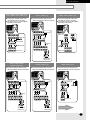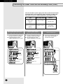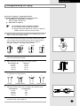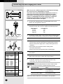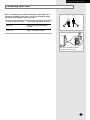
1
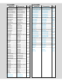
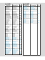
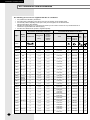
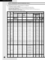
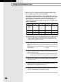
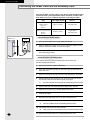
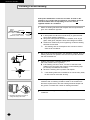
The Classified Table
La tabla de clasificación
La Tabella di Classificazione
A Tabela de Classificação
Le tableau de classification
Die Klassifizierte Tabelle
C✴✴✴✴
H✴✴✴✴
The type with letter C
means that the air
conditioner is only for
cooling.
The type with letter H
means that the air
conditioner is not only
cooling but also heating.
INDOOR UNIT
OUTDOOR UNIT
TYPE
El modelo con la letra
C significa que el aire
acondicionador es
sólo para el
enfriamiento.
El modelo con la letra H
significa que el aire
acondicionador no sólo es
para el enfriamiento sino
para la calefaccióntambién.
UNIDAD
INTERIOR
UNIDAD EXTERIOR
TIPO
Il tipo con la lettera C
significa che il
condizionatore d'aria
e' solo per raffreddare.
Il tipo con la lettera H
significa che il
condizionatore d'aria e'
non solo per raffreddare
ma anche per riscaldare.
UNITÀ INTERNA
UNITÀ ESTERNA
TIPO
O tipo com a letra C
significa que o
aparelho é só para
refrigeração.
O tipo com a letra H significa
que o aparelho é não só
para refrigeração mas
também para calefação.
UNIDADE
INTERIOR
UNIDADE
EXTERIOR
TIPO
French
Le manuel d'installation est le même pour tous Les modèles de type
C ne sont destinés
les modèles. S'assurer donc des
qu'au refroidissement.
caractéristiques de votre climatiseur.
L'installer selon ses caractéristiques.
Les modèles de type H sont
destinés non seulement au
refroidissement mais aussi
au chauffage.
UNITÉ
INTÉRIEURE
UNITÉ
EXTÉRIEURE
TYPE
German
Dieses Aufstellungshandbuch ist der Modus für
die verschiedenen Modelle. Drum, das Modell,
das Sie gekauft haben, sicherstellen, und dann
Ihre Klimaanlage installieren nach ihrem Typ.
Der Typ mit dem
Buchstabe C bedeutet
daß die Klimaanlage
nur für das Kühlen ist.
Der Typ mit dem Buchstabe H
bedeutet daß die Klimaanlage
nicht nur für des Kühlen aber
auch für das Heizen ist.
INNENRAUM
EINHEIT
AUSSENEINHEIT
TYP
Pada jenis dengan
huruf “C” artinya alat
penyejuk udara jenis
ini hanya untuk
pendingin.
Pada jenis dengan huruf
“H” artinya alat penyejuk
udara jenis ini tidak hanya
untuk pendingin etapi
juga untuk pemanas.
UNIT DALAM
UNIT LUAR
JENIS
English
This installation manual is made for various
models. Thus, make sure the model which
you purchased, then install your air conditioner
according to your type.
Spanish Este manual de instalación está hecha para
varios modelos. Por lo tanto, verifique el
modelo que ha comprado y luego instale su
aire acondicionador de acuerdo a su modelo.
Italian
Questo manuale per l'installazione e' stato
fatto per vari modelli. Percio' assicuratevi il
modello che avete acquistato, e poi installate il
vostro condizionatore d'aria a seconda del
vostro tipo.
Portuguese Este manual de instalação é para vários
modelos. Por isso, verifique o modelo
comprado e instale o seu aparelho de acordo
com o tipo correspondente.
Greek
Russian
Turkish
Arab
Chinese
Indonesian Petunjuk pemasangan ini dibuat untuk
berbagai model. Dengan demikian model apa
yang telah anda beli, kemudian pasanglah
alat penyejuk udara anda sesuai dengan
jenisnya.
DB98-03781A(12)
7000 BTU
INDOOR UNIT
AQ07A1(A2)(A5)(A6)MB/C/D/E
7000 BTU
OUTDOOR UNIT
TYPE
UQ07A1(A2)(A5)(A6)MB/C/D/E
INDOOR UNIT
OUTDOOR UNIT
TYPE
SC07ZB3(B4)(B7)(B8)A
SC07ZB3(B4)(B7)(B8)X
CM020
SC07AC5(6)
SC07AC5(6)X
CM052
HM070
AQ07B1(B2)(B5)(B6)MB/C/D/E
UQ07B1(B2)(B5)(B6)MB/C/D/E
AQ07A3(A4)(A7)(A8)MB/C/D/E
UQ07A3(A4)(A7)(A8)MB/C/D/E
AQ07B3(B4)(B7)(B8)MB/C/D/E
UQ07B3(B4)(B7)(B8)MB/C/D/E
AQ07A5(6)MB(E)D
UQ07A5(6)MB(E)D
AQ07B5(6)MB(E)D
UQ07B5(6)MB(E)D
AQ07C5(6)MB(E)
UQ07C5(6)MB(E)
AQ07C5(6)MB(E)D
UQ07C5(6)MB(E)D
AQ07C7(8)ME
UQ07C7(8)ME
SH07ZA1(A2)(A5)(A6)
SH07ZA1(A2)(A5)(A6)X
SH07ZB1(B2)(B5)(B6)
SH07ZB1(B2)(B5)(B6)X
SH07ZA1(A2)(A5)(A6)A
SH07ZA1(A2)(A5)(A6)X
SH07ZB1(B2)(B5)(B6)A
SH07ZB1(B2)(B5)(B6)X
SH07ZA5(6)D
SH07ZA5(6)DX
SH07ZB5(6)D
SH07ZB5(6)DX
SH07AA5
SH07AA5X
SH07AB5
SH07AB5X
SH07ZA3(A4)(A7)(A8)
SH07ZA3(A4)(A7)(A8)X
SH07ZB3(B4)(B7)(B8)
SH07ZB3(B4)(B7)(B8)X
SH07ZA3(A4)(A7)(A8)A
SH07ZA3(A4)(A7)(A8)X
SH07ZB3(B4)(B7)(B8)A
SH07ZB3(B4)(B7)(B8)X
SH07AC5(6)
SH07AC5(6)X
AS07A1(A2)(A5)(A6)MB/C/D/E
US07A1(A2)(A5)(A6)MB/C/D/E
AS07B1(B2)(B5)(B6)MB/C/D/E
US07B1(B2)(B5)(B6)MB/C/D/E
AS07A3(A4)(A7)(A8)MB/C/D/E
US07A3(A4)(A7)(A8)MB/C/D/E
AS07B3(B4)(B7)(B8)MB/C/D/E
US07B3(B4)(B7)(B8)MB/C/D/E
AS07A5(A6)MA
US07A5(A6)MA
AS07B5(B6)MA
US07B5(B6)MA
AS07A5(6)MB(D)(E)D
US07A5(6)MB(D)(E)D
AS07B5(6)MB(D)(E)D
US07B5(6)MB(D)(E)D
AS07C5(6)MB(E)
US07C5(6)MB(E)
AS07C5(6)MB(D)(E)D
US07C5(6)MB(D)(E)D
AS07C7(8)ME(D)
US07C7(8)ME(D)
SC07ZA1(A2)(A5)(A6)
SC07ZA1(A2)(A5)(A6)X
SC07ZB1(B2)(B5)(B6)
SC07ZB1(B2)(B5)(B6)X
SC07ZA1(A2)(A5)(A6)A
SC07ZA1(A2)(A5)(A6)X
SC07ZB1(B2)(B5)(B6)A
SC07ZB1(B2)(B5)(B6)X
SC07ZA5(6)D
SC07ZA5(6)DX
SC07ZB5(6)D
SC07ZB5(6)DX
SC07AA5
SC07AA5X
SC07AB5
SC07AB5X
SC07ZA3(A4)(A7)(A8)
SC07ZA3(A4)(A7)(A8)X
SC07ZB3(B4)(B7)(B8)
SC07ZB3(B4)(B7)(B8)X
SC07ZA3(A4)(A7)(A8)A
SC07ZA3(A4)(A7)(A8)X
HM020
HM070
HM070
HM070
HM070
HM070
HM070
HM071
HM020
HM020
HM071
CM050
CM020
CM050
CM052
CM052
CM052
CM050
CM050
CM052
CM051
CM020
CM020
9000 BTU
INDOOR UNIT
AQ09A1(A2)MB/C/D/E
9000 BTU
OUTDOOR UNIT
TYPE
UQ09A1(A2)MB/C/D/E
INDOOR UNIT
OUTDOOR UNIT
AS09A3(A4)(A7)(A8)MB/C/D/E
US09A3(A4)(A7)(A8)MB/C/D/E
AS09B3(B4)(B7)(B8)MB/C/D/E
US09B3(B4)(B7)(B8)MB/C/D/E
AS09A5(A6)MB/C/D/E
US09A5(A6)MB/C/D/E
AS09B5(B6)MB/C/D/E
US09B5(B6)MB/C/D/E
AS09A5(6)MB(D)(E)D
US09A5(6)MB(D)(E)D
AS09B5(6)MB(D)(E)D
US09B5(6)MB(D)(E)D
AS09C5(6)MB(D)(E)D
US09C5(6)MB(D)(E)D
CM052
AS09C5(6)MB(E)
US09C5(6)MB(E)
CM050
AS09C7(8)ME(D)
US09C7(8)ME(D)
CM052
AS09A5(A6)MA
US09A5(A6)MA
AS09B5(B6)MA
US09B5(B6)MA
SC09ZA1(A2)
SC09ZA1(A2)X
SC09ZB1(B2)
SC09ZB1(B2)X
SC09ZA1(A2)A
SC09ZA1(A2)X
SC09ZB1(B2)A
SC09ZB1(B2)X
SC09ZA3(A4)(A7)(A8)
SC09ZA3(A4)(A7)(A8)X
SC09ZB3(B4)(B7)(B8)
SC09ZB3(B4)(B7)(B8)X
SC09ZA3(A4)(A7)(A8)A
SC09ZA3(A4)(A7)(A8)X
SC09ZB3(B4)(B7)(B8)A
SC09ZB3(B4)(B7)(B8)X
CM020
HM040
AQ09B1(B2)MB/C/D/E
UQ09B1(B2)MB/C/D/E
AQ09A3(A4)(A7)(A8)MB/C/D/E
UQ09A3(A4)(A7)(A8)MB/C/D/E
CM050
HM020
AQ09B3(B4)(B7)(B8)MB/C/D/E
UQ09B3(B4)(B7)(B8)MB/C/D/E
AQ09A5(A6)MB/C/D/E
UQ09A5(A6)MB/C/D/E
AQ09B5(B6)MB/C/D/E
UQ09B5(B6)MB/C/D/E
AQ09A5(6)MB(D)(E)D
UQ09A5(6)MB(D)(E)D
AQ09B5(6)MB(D)(E)D
UQ09B5(6)MB(D)(E)D
AQ09C5(6)MB(E)
UQ09C5(6)MB(E)
AQ09C5(6)MB(D)(E)D
UQ09C5(6)MB(D)(E)D
AQ09C7(8)ME
UQ09C7(8)ME
AQV09A1(A2)MD/E
UQV09A1(A2)MD/E
TYPE
CM052
HM070
HM070
HM070
HM070
HM060
AQV09B1(B2)MD/E
UQV09B1(B2)MD/E
AQV09A5(A6)MD/E
UQV09A5(A6)MD/E
HM100
AQV09B5(B6)MD/E
UQV09B5(B6)MD/E
AQV09AC(D)ME
UQV09AC(D)ME
AQV09BC(D)ME
UQV09BC(D)ME
AQV09F2VE/D
UQV09A0TE/D
SH09VA1(A2)
SH09VA1(A2)X
SH09VB1(B2)
SH09VB1(B2)X
SC09ZA5(A6)
SC09ZA5(A6)X
SH09VA5(A6)
SH09VA5(A6)X
SC09ZB5(B6)
SC09ZB5(B6)X
SH09VB5(B6)
SH09VB5(B6)X
SC09ZA5(A6)A
SC09ZA5(A6)X
SH09VCD
SH09VCDX
SC09ZB5(B6)A
SC09ZB5(B6)X
SH09VAC(D)
SH09VAC(D)X
SC09ZA5(6)D
SC09ZA5(6)DX
SH09VBC(D)
SH09VBC(D)X
SC09ZB5(6)D
SC09ZB5(6)DX
SH09ZA1(A2)
SH09ZA1(A2)X
SC09AA5
SC09AA5X
SH09ZB1(B2)
SH09ZB1(B2)X
SC09AB5
SC09AB5X
SH09ZA1(A2)A
SH09ZA1(A2)X
SC09ACA(B)
SC09ACA(B)X
SH09ZB1(B2)A
SH09ZB1(B2)X
SH09ZA3(A4)(A7)(A8)
SH09ZA3(A4)(A7)(A8)X
SH09ZB3(B4)(B7)(B8)
SH09ZB3(B4)(B7)(B8)X
SH09ZA3(A4)(A7)(A8)A
SH09ZA3(A4)(A7)(A8)X
SH09ZB3(B4)(B7)(B8)A
SH09ZB3(B4)(B7)(B8)X
SH09ZA5(A6)
SH09ZA5(A6)X
SH09ZB5(B6)
SH09ZB5(B6)X
SH09ZA5(A6)A
SH09ZA5(A6)X
SH09ZB5(B6)A
SH09ZB5(B6)X
SH09ZA5(6)D
SH09ZA5(6)DX
SH09ZB5(6)D
SH09ZB5(6)DX
SH09AA5
SH09AA5X
SH09AB5
SH09AB5X
SH09ACA(B)
SH09ACA(B)X
AS09A1(A2)MB/C/D/E
US09A1(A2)MB/C/D/E
AS09B1(B2)MB/C/D/E
US09B1(B2)MB/C/D/E
HM130
HT010
HM060
HM100
HM130
HM130
HM040
HM040
HM020
HM020
HM070
HM070
HM070
HM081
HM110
CM040
CM050
CM040
CM040
CM020
CM020
CM050
CM050
CM052
CM061
CM070
12000 BTU
INDOOR UNIT
12000 BTU
OUTDOOR UNIT
TYPE
AQ12A1(A2)(A9)(A0)MB/C/D/E/EA UQ12A1(A2)(A9)(A0)MB/C/D/E/EA
INDOOR UNIT
OUTDOOR UNIT
SH12AB5
SH12AB5X
AQ12B1(B2)(B9)(B0)MB/C/D/E/EA UQ12B1(B2)(B9)(B0)MB/C/D/E/EA
SH12ZA9(A0)
SH12ZA9(A0)X
AQ12A3(A4)(A7)(A8)MB/C/D/E/EA UQ12A3(A4)(A7)(A8)MB/C/D/E/EA
SH12ZB9(B0)
SH12ZB9(B0)X
SH12ACA(B)
SH12ACA(B)X
TYPE
HM081
HM030
HM030
HM010
AQ12B3(B4)(B7)(B8)MB/C/D/E/EA UQ12B3(B4)(B7)(B8)MB/C/D/E/EA
AQ12A5(A6)MB/C/D/E/EA
UQ12A5(A6)MB/C/D/E/EA
AQ12B5(B6)MB/C/D/E/EA
UQ12B5(B6)MB/C/D/E/EA
AQ12AA(B)MB(D)(E)
UQ12AA(B)MB(D)(E)
AQ12BA(B)MB(D)(E)
UQ12BA(B)MB(D)(E)
AQ12CA(B)MB(D)(E)
UQ12CA(B)MB(D)(E)
AQV12A1(A2)MD/E
UQV12A1(A2)MD/E
HM110
AS12A1(A2)(A9)(A0)MB/C/D/E/EA US12A1(A2)(A9)(A0)MB/C/D/E/EA
HM080
AS12B1(B2)(B9)(B0)MB/C/D/E/EA US12B1(B2)(B9)(B0)MB/C/D/E/EA
AS12C1(2)MD
CM030
US12C1(2)MD
HM111
AQV12B1(B2)MD/E
UQV12B1(B2)MD/E
AQV12A5(A6)MD/E
UQV12A5(A6)MD/E
AQV12B5(B6)MD/E
UQV12B5(B6)MD/E
AQV12AC(D)ME
UQV12AC(D)ME
AQV12BC(D)ME
UQV12BC(D)ME
AQV12F2VE/D
UQV12A0TE/D
SH12VA1(A2)
SH12VA1(A2)X
AS12A3(A4)(A7)(A8)MB/C/D/E/EA US12A3(A4)(A7)(A8)MB/C/D/E/EA
HM111
HM050
HM090
HM120
CM010
AS12B3(B4)(B7)(B8)MB/C/D/E/EA US12B3(B4)(B7)(B8)MB/C/D/E/EA
AS12A5(A6)MB/C/D/E/EA
US12A5(A6)MB/C/D/E/EA
AS12B5(B6)MB/C/D/E/EA
US12B5(B6)MB/C/D/E/EA
AS12AA(B)MB(E)
US12AA(B)MB(E)
AS12BA(B)MB(E)
US12BA(B)MB(E)
AS12CA(B)MB(E)
US12CA(B)MB(E)
SC12ZA1(A2)
SC12ZA1(A2)X
SC12ZB1(B2)
SC12ZB1(B2)X
SC12ZA1(A2)A
SC12ZA1(A2)XA
SC12ZB1(B2)A
SC12ZB1(B2)XA
SC12ZA1(A2)B
SC12ZA1(A2)X
SC12ZB1(B2)B
SC12ZB1(B2)X
SC12ZA3(A4)(A7)(A8)
SC12ZA3(A4)(A7)(A8)X
SC12ZB3(B4)(B7)(B8)
SC12ZB3(B4)(B7)(B8)X
CM060
CM071
CM071
CM030
HT020
CM030
HM050
SH12VB1(B2)
SH12VB1(B2)X
SH12VA5(A6)
SH12VA5(A6)X
CM030
HM090
SH12VB5(B6)
SH12VB5(B6)X
SH12VCD
SH12VCDX
SH12VAC(D)
SH12VAC(D)X
SH12VBC(D)
SH12VBC(D)X
SC12ZA3(A4)(A7)(A8)A
SC12ZA3(A4)(A7)(A8)XA
SH12ZA1(A2)
SH12ZA1(A2)X
SC12ZB3(B4)(B7)(B8)A
SC12ZB3(B4)(B7)(B8)XA
SH12ZB1(B2)
SH12ZB1(B2)X
SC12ZA3(A4)(A7)(A8)B
SC12ZA3(A4)(A7)(A8)X
SH12ZA1(A2)A
SH12ZA1(A2)XA
SC12ZB3(B4)(B7)(B8)B
SC12ZB3(B4)(B7)(B8)X
SH12ZB1(B2)A
SH12ZB1(B2)XA
SC12ZA5(A6)
SC12ZA5(A6)X
SH12ZA1(A2)B
SH12ZA1(A2)X
SC12ZB5(B6)
SC12ZB5(B6)X
SH12ZB1(B2)B
SH12ZB1(B2)X
SC12ZA5(A6)A
SC12ZA5(A6)XA
SH12ZA3(A4)(A7)(A8)
SH12ZA3(A4)(A7)(A8)X
SC12ZB5(B6)A
SC12ZB5(B6)XA
SH12ZB3(B4)(B7)(B8)
SH12ZB3(B4)(B7)(B8)X
SC12ZA5(A6)B
SC12ZA5(A6)X
SH12ZA3(A4)(A7)(A8)A
SH12ZA3(A4)(A7)(A8)XA
SC12ZB5(B6)B
SC12ZB5(B6)X
SH12ZB3(B4)(B7)(B8)A
SH12ZB3(B4)(B7)(B8)XA
SC12ZAA(B)
SC12ZAA(B)X
SH12ZA3(A4)(A7)(A8)B
SH12ZA3(A4)(A7)(A8)X
SC12ZBA(B)
SC12ZBA(B)X
SC12AA5
SC12AA5X
SC12AB5
SC12AB5X
SC12ZA9(A0)
SC12ZA9(A0)X
SC12ZB9(B0)
SC12ZB9(B0)X
SC12ACA(B)
SC12ACA(B)X
HM120
CM010
HM120
CM010
HM030
CM010
HM030
CM060
HM030
CM060
HM010
CM060
HM010
CM071
HM010
SH12ZB3(B4)(B7)(B8)B
SH12ZB3(B4)(B7)(B8)X
SH12ZA5(A6)
SH12ZA5(A6)X
CM061
HM080
SH12ZB5(B6)
SH12ZB5(B6)X
SH12ZA5(A6)A
SH12ZA5(A6)XA
CM030
HM080
SH12ZB5(B6)A
SH12ZB5(B6)XA
SH12ZA5(A6)B
SH12ZA5(A6)X
SH12ZB5(B6)B
SH12ZB5(B6)X
SH12ZAA(B)
SH12ZAA(B)X
CM070
HM080
14000 BTU
HM111
SH12ZBA(B)
SH12ZBA(B)X
SH12AA5
SH12AA5X
HM081
INDOOR UNIT
AS14ABTB
OUTDOOR UNIT
US14ABTB
TYPE
CM072
18000 BTU
INDOOR UNIT
18000 BTU
OUTDOOR UNIT
AQ18A1(A2)RE/B/C/D
UQ18A1(A2)RE/B/C/D
AQ18B1(B2)RE/B/C/D
UQ18B1(B2)RE/B/C/D
AQ18A5(A6)RE/B/C/D
UQ18A5(A6)RE/B/C/D
AQ18B5(B6)RE/B/C/D
UQ18B5(B6)RE/B/C/D
AQ18A9(A0)RE/B/C/D
UQ18A9(A0)RE/B/C/D
AQ18B9(B0)RE/B/C/D
UQ18B9(B0)RE/B/C/D
AQ18A9(0)RB(C)(D)(E)D
UQ18A9(0)RB(C)(D)(E)D
TYPE
INDOOR UNIT
OUTDOOR UNIT
AST18A9(0)REF
UST18A9(0)REF
AST18C9(0)REF
UST18C9(0)REF
SC18TA1(A2)(A9)(A0)
SC18TA1(A2)(A9)(A0)X
SC18TB1(B2)(B9)(B0)
SC18TB1(B2)(B9)(B0)X
SC18TA5(A6)
SC18TA5(A6)X
SC18TB5(B6)
SC18TB5(B6)X
SC18ZA1(A2)
SC18ZA1(A2)X
SC18ZB1(B2)
SC18ZB1(B2)X
SC18ZA9(A0)
SC18ZA9(A0)X
SC18ZB9(B0)
SC18ZB9(B0)X
SC18ZA9(0)D
SC18ZA9(0)DX
SC18ZB9(0)D
SC18ZB9(0)DX
SC18ZA5(A6)
SC18ZA5(A6)X
SC18ZB5(B6)
SC18ZB5(B6)X
SC18AC9(0)
SC18AC9(0)X
HR020
CR070
HR010
CR040
HR020
CR030
HR020
AQ18B9(0)RB(C)(D)(E)D
UQ18B9(0)RB(C)(D)(E)D
AQ18C9(0)RB(C)(D)(E)D
UQ18C9(0)RB(C)(D)(E)D
AQT18A1(A2)(A9)(A0)RE/B/C/D
UQT18A1(A2)(A9)(A0)RE/B/C/D
AQT18B1(B2)(B9)(B0)RE/B/C/D
UQT18B1(B2)(B9)(B0)RE/B/C/D
AQT18A5(A6)RE/B/C/D
UQT18A5(A6)RE/B/C/D
AQT18B5(B6)RE/B/C/D
UQT18B5(B6)RE/B/C/D
AQT18C9(0)RB(E)
UQT18C9(0)RB(E)
AQT18A9(0)REF
UQT18A9(0)REF
HR020
TYPE
CR020
CR060
HR040
CR060
HR030
CR010
AQT18C9(0)REF
UQT18C9(0)REF
SH18AC9(0)
SH18AC9(0)X
SH18TA1(A2)(A9)(A0)
SH18TA1(A2)(A9)(A0)X
SH18TB1(B2)(B9)(B0)
SH18TB1(B2)(B9)(B0)X
SH18TA5(A6)
SH18TA5(A6)X
SH18TB5(B6)
SH18TB5(B6)X
SH18ZA1(A2)(A9)(A0)
SH18ZA1(A2)(A9)(A0)X
SH18ZB1(B2)(B9)(B0)
SH18ZB1(B2)(B9)(B0)X
SH18ZA5(A6)
SH18ZA5(A6)X
SH18ZB5(B6)
SH18ZB5(B6)X
SH18ZA9(0)D
SH18ZA9(0)DX
SH18ZB9(0)D
SH18ZB9(0)DX
AS18A1(A2)RE/B/C/D
US18A1(A2)RE/B/C/D
AS18B1(B2)RE/B/C/D
US18B1(B2)RE/B/C/D
AS18A5(A6)RE/B/C/D
US18A5(A6)RE/B/C/D
AS18B5(B6)RE/B/C/D
US18B5(B6)RE/B/C/D
AS18A9(A0)RE/B/C/D
US18A9(A0)RE/B/C/D
AS18B9(B0)RE/B/C/D
US18B9(B0)RE/B/C/D
AS18A9(0)RB(C)(D)(E)D
US18A9(0)RB(C)(D)(E)D
AS18B9(0)RB(C)(D)(E)D
US18B9(0)RB(C)(D)(E)D
AS18C9(0)RB(C)(D)(E)D
US18C9(0)RB(C)(D)(E)D
AS18C9(0)RD
US18C9(0)RD
AST18A1(A2)(A9)(A0)RE/B/C/D
UST18A1(A2)(A9)(A0)RE/B/C/D
AST18B1(B2)(B9)(B0)RE/B/C/D
UST18B1(B2)(B9)(B0)RE/B/C/D
AST18A5(A6)RE/B/C/D
UST18A5(A6)RE/B/C/D
AST18B5(B6)RE/B/C/D
UST18B5(B6)RE/B/C/D
AST18C9(0)RB(E)
UST18C9(0)RB(E)
HR040
HR040
HR041
HR040
HR030
HR020
HR010
HR020
CR020
CR010
CR060
CR060
CR060
CR040
CR030
CR040
CR061
24000 BTU
INDOOR UNIT
30000 BTU
OUTDOOR UNIT
AQ24A1(A2)RE/B/C/D
UQ24A1(A2)RE/B/C/D
AQ24B1(B2)RE/B/C/D
UQ24B1(B2)RE/B/C/D
AQ24A5(6)RB(C)(D)(E)D
UQ24A5(6)RB(C)(D)(E)D
AQ24B5(6)RB(C)(D)(E)D
UQ24B5(6)RB(C)(D)(E)D
AQ24C5(6)RB(C)(D)(E)D
UQ24C5(6)RB(C)(D)(E)D
TYPE
INDOOR UNIT
OUTDOOR UNIT
AQT30C1(C2)BB
UQT30C1(C2)BB
AQT30C1(C2)BE
UQT30C1(C2)BE
AQT32C1(C2)BE
UQT32C1(C2)BE
SH30ZA2
SH30ZA2X
SH30ZC1(C2)
SH30ZC1(C2)X
AS30C1(C2)(C3)(C4)BB
US30C1(C2)(C3)(C4)BB
AS30C1(C2)(C3)(C4)BC
US30C1(C2)(C3)(C4)BC
AS36C1(C2)(C3)(C4)BB
US36C1(C2)(C3)(C4)BB
AS36C1(C2)(C3)(C4)BC
US36C1(C2)(C3)(C4)BC
AST30C1(C2)BB
UST30C1(C2)BB
AST30C1(C2)(C3)(C4)BE
UST30C1(C2)(C3)(C4)BE
AST32C1(C2)BE
UST32C1(C2)BE
SC30ZA2
SC30ZA2X
SC30ZC1(C2)(C3)(C4)
SC30ZC1(C2)(C3)(C4)X
TYPE
HR050
HB010
HR050
HR050
AQT24A1(A2)(A5)(A6)(A8)RE/B/C/D UQT24A1(A2)(A5)(A6)(A8)RE/B/C/D
AQT24B1(B2)(B5)(B6)(B8)RE/B/C/D UQT24B1(B2)(B5)(B6)(B8)RE/B/C/D
AQT24A5(6)RE(B)D
UQT24A5(6)RE(B)D
AQT24B5(6)RE(B)D
UQT24B5(6)RE(B)D
AQT24C5(6)RB(E)
UQT24C5(6)RB(E)
AQT24C5(6)RB(E)D
UQT24C5(6)RB(E)D
SH24TA1(A2)(A5)(A6)(A8)
SH24TA1(A2)(A5)(A6)(A8)X
SH24TB1(B2)(B5)(B6)(B8)
SH24TB1(B2)(B5)(B6)(B8)X
SH24TA5(6)(8)D
SH24TA5(6)(8)DX
SH24TB5(6)(8)D
SH24TB5(6)(8)DX
SH24AC5(6)
SH24AC5(6)X
AS24A1(A2)RE/B/C/D
US24A1(A2)RE/B/C/D
AS24B1(B2)RE/B/C/D
US24B1(B2)RE/B/C/D
AS24A5(6)RB(C)(D)(E)D
US24A5(6)RB(C)(D)(E)D
AS24B5(6)RB(C)(D)(E)D
US24B5(6)RB(C)(D)(E)D
AS24C5(6)RB(C)(D)(E)D
US24C5(6)RB(C)(D)(E)D
AST24A1(A2)(A5)(A6)(A8)RE/B/C/D
US24B5(6)RCDX
AST24B1(B2)(B5)(B6)(B8)RE/B/C/D
UST24A1(A2)(A5)(A6)(A8)RE/B/C/D
AST24A5(6)RE(B)D
UST24B1(B2)(B5)(B6)(B8)RE/B/C/D
AST24B5(6)RE(B)D
UST24A5(6)RE(B)D
AST24C5(6)RB(E)
UST24C5(6)RB(E)
AST24C5(6)RB(E)D
UST24C5(6)RB(E)D
AST24C6RE/MID
UST24C6RE/MID
SC24TA1(A2)(A5)(A6)(A8)
SC24TA1(A2)(A5)(A6)(A8)X
SC24TB1(B2)(B5)(B6)(B8)
SC24TB1(B2)(B5)(B6)(B8)X
SC24TA5(6)(8)D
SC24TA5(6)(8)DX
SC24TB5(6)(8)D
SC24TB5(6)(8)DX
SC24AC5(6)
SC24AC5(6)X
HR050
HR050
HR050
HR050
HR050
HR051
CR050
CR050
CR050
CR050
CR050
CR050
CR052
CR050
CR050
CR051
CB010
INSTALLATION MANUAL
Split-type Room Air Conditioner
http://www.yesmanual.com
[ This installation manual is written in English. If you would like to read in another language, please visit our homepage. ]
Contents
◆
PREPARING THE INSTALLATION
■
Deciding on Where to Install the Air Conditioner . . . . . . . . . . . . . . 2
■
Air Conditioner and Accessories . . . . . . . . . . . . . . . . . . . . . . . . . 4
◆
INSTALLING THE UNIT
■
Fixing the Installation Plate . . . . . . . . . . . . . . . . . . . . . . . . . . . . . .
■
Connecting the Power Cable and the
Assembly Cable . . . . . . . . . . . . . . . . . . . . . . . . . . . . . . . . . . . . . .
■
Checking Correct Earthing . . . . . . . . . . . . . . . . . . . . . . . . . . . . . .
■
Fixing the Unit in Position . . . . . . . . . . . . . . . . . . . . . . . . . . . . . . .
■
Purging the Unit . . . . . . . . . . . . . . . . . . . . . . . . . . . . . . . . . . . . . .
■
Installing and Connecting the Indoor Unit
Drain Hose . . . . . . . . . . . . . . . . . . . . . . . . . . . . . . . . . . . . . . . . . .
■
Installing and Connecting the Outdoor Unit
Drain Hose (H✴✴✴✴ Type Only) . . . . . . . . . . . . . . . . . . . . . . . . .
■
Installing and Connecting the Indoor Unit
Assembly Piping . . . . . . . . . . . . . . . . . . . . . . . . . . . . . . . . . . . . . .
■
Cutting/Extending the Piping . . . . . . . . . . . . . . . . . . . . . . . . . . . . .
◆
COMPLETING THE INSTALLATION
■
Connecting Up and Purging the Circuit . . . . . . . . . . . . . . . . . . . . .
■
Performing Leak Tests . . . . . . . . . . . . . . . . . . . . . . . . . . . . . . . . .
■
Placing the Indoor Unit in Position . . . . . . . . . . . . . . . . . . . . . . . .
■
Checking and Testing Operations . . . . . . . . . . . . . . . . . . . . . . . .
■
Explaining Operations to the Owner . . . . . . . . . . . . . . . . . . . . . .
The design and shape are subject to change according to the model.
8
10
14
15
16
16
17
18
19
20
21
22
23
23
PREPARING THE INSTALLATION
Deciding on Where to Install the Air Conditioner
When deciding on the location of the air conditioner with the owner, the following restrictions must
be taken into account.
General
Do NOT install the air conditioner in a location where it will come into contact with the following elements:
◆ Combustible gases
◆ Saline air
◆ Machine oil
◆ Sulphide gas
◆ Special environmental conditions
If you must install the unit in such conditions, first consult your dealer.
Indoor Unit
◆ There must be no obstacles near the air inlet and outlet.
◆ Install the indoor unit on a surface that can support its weight.
◆ Choose a position that enables the piping and cables to be easily connected to the outdoor unit and the
recommended length of 5 metres to be respected (“L” metres maximum).
◆ Leave enough clearance beneath the indoor unit to enable the filters to be removed without hindrance.
◆ Maintain sufficient clearance around the indoor unit, as indicated in the diagram on the page opposite.
◆ Make sure that the water dripping from the drain hose runs away correctly and safely.
◆ Install the indoor unit on the wall which is far from the floor by more than 2.5meters.
Outdoor Unit
◆ The outdoor unit must NEVER be placed on its side or upside down, as the compressor lubrication oil will run
into the cooling circuit and seriously damage the unit.
◆ Choose a location that is dry and sunny, but not exposed to direct sunlight or strong winds.
◆ Do not block any passageways or thoroughfares.
◆ Choose a location where the noise of the air conditioner when running and the discharged air do not disturb
any neighbours.
◆ Choose a position that enables the piping and cables to be easily connected to the indoor unit and the
recommended length of 5 metres to be respected (“L” metres maximum).
◆ Install the outdoor unit on a flat, stable surface that can support its weight and does not generate any
unnecessary noise and vibration.
◆ Position the outdoor unit so that the air flow is directed towards the outside, as indicated by the arrows on the
top of the unit.
◆ Maintain sufficient clearance around the outdoor unit, as indicated in the diagram on the page opposite.
◆ If the outdoor unit is installed at a height, ensure that its base is firmly fixed in position;
the maximum height is “H” metres.
◆ Make sure that the water dripping from the drain hose runs away correctly and safely.
CAUTION
◆ You have just purchased a split-type room air conditioner and it has been installed by
your installation specialist.
◆ This device must be installed according to the national electrical rules.
E-2
PREPARING THE INSTALLATION
Respect the clearances and maximum lengths indicated in the diagram below when installing
the unit.
300 mm or more
125 mm
or more
125 mm
or more
“H” metres maximum
600 mm
minimum
“L” metres
maximum
300 mm
minimum
300 mm
minimum
350 mm
minimum
600 mm
minimum
Type
L
H
CM✴✴✴
HM✴✴✴
HT✴✴✴
15
7
CB✴✴✴
CR05✴
HB✴✴✴
HR05✴
20
8
✴R010
✴R020
✴R030
✴R04✴
✴R06✴
CR070
15
8
The designs of the unit and the connection valve are subject to change according to the model.
The illustrations in the step-by-step procedures use four different symbols:
PRESS
PUSH
☛
➢
IMPORTANT
NOTE
E-3
PREPARING THE INSTALLATION
Air Conditioner and Accessaries
The following accessories are supplied with the air conditioner.
➢ The quantities are indicated in parentheses.
➢ The power cable is depending on the option. If they are not supplied, use the standard cable.
➢ The assembly cable is depending on the option. If they are not supplied, use the standard cable.
(approved according to IEC standard.)
➢ The flare nuts, drain plug(H✴✴✴✴ Type Only) and rubber leg in the outdoor unit case are only included when the air
conditioner is supplied without the assembly piping.
➢ The flare nut is attached to the product or supplied separately.
Accessaries in the Indoor Unit Case
Type
E-4
Reference
Shape
-
Specification
-
Installation Plate
-
Accessaries in the Outdoor Unit Case
Flare Nut (option)
Remote Control
&
Battery
Owner’s
Instructions
Booklet &
Installation
Manual
Cable
-
-
-
-
-
-
-
Drain
Plug
Rubber
Leg
-
-
-
(2)
15.88mm(2)
-
(4)
Ø9.52mm
Ø6.35mm Ø12.70mm
Ø15.88mm
CB010
-
(1)
(1) (2)
(1) (1)
0.75mm2x2G+1.0mm2x4G
2.5mm2x3G
CM010
M/D
(1)
(1) (2)
(1) (1)
1.0mm x3G
(2)
12.70mm(2)
-
(4)
CM020
M/D
(1)
(1) (2)
(1) (1)
1.0mm2x3G
(2)
9.52mm(2)
-
(4)
CM030
P/D
(1)
(1) (2)
(1) (1)
1.0mm2x3G
(2)
12.70mm(2)
-
(4)
CM040
P/D
(1)
(1) (2)
(1) (1)
1.0mm x3G
(2)
9.52mm(2)
-
(4)
CM050
A
(1)
(1) (2)
(1) (1)
1.0mm x3G
(2)
9.52mm(2)
-
(4)
CM051
R410A,A
(1)
(1) (2)
(1) (1)
1.0mm2x3G
(2)
9.52mm(2)
-
(4)
CM052
R410A,A
(1)
(1) (2)
(1) (1)
1.0mm x3G
(2)
9.52mm(2)
-
(4)
CM060
T
(1)
(1) (2)
(1) (1)
1.0mm x3G
(2)
12.70mm(2)
-
(4)
CM061
R410A,T
(1)
(1) (2)
(1) (1)
1.0mm2x3G
(2)
9.52mm(2)
-
(4)
CM070
R410A,
ACTIVE
(1)
(1) (2)
(1) (1)
1.0mm x3G
(2)
9.52mm(2)
-
(4)
CM071
ACTIVE
(1)
(1) (2)
(1) (1)
1.0mm x3G
(2)
12.70mm(2)
-
(4)
CM072
ACTIVE,T2
(1)
(1) (2)
(1) (1)
1.0mm x3G
(2)
12.70mm(2)
-
(4)
1.0mm2x5G
2.5mm2x3G
0.75mm2x2G+1.0mm2x4G
2.5mm2x3G
1.0mm2x5G
2.5mm2x3G
0.75mm2x2G+1.0mm2x4G
2.5mm2x3G
0.75mm2x2G+1.0mm2x4G
2.5mm2x3G
(2)
12.70mm(2)
-
(4)
(2)
12.70mm(2)
-
(4)
(2)
12.70mm(2)
-
(4)
(2)
12.70mm(2)
-
(4)
(2)
15.88mm(2)
-
(4)
CR010
-
(1)
(1) (2)
(1) (1)
CR020
-
(1)
(1) (2)
(1) (1)
CR030
-
(1)
(1) (2)
(1) (1)
CR040
-
(1)
(1) (2)
(1) (1)
CR050
-
(1)
(1) (2)
(1) (1)
2
2
2
2
2
2
2
2
CR051
R410A,Q
(1)
(1) (2)
(1) (1)
0.75mm x2G+1.0mm x4G
2.5mm2x3G
(2)
15.88mm(2)
-
(4)
CR052
-
(1)
(1) (2)
(1) (1)
2.0mm x3G
(2)
15.88mm(2)
-
(4)
1.0mm2x4G
2.5mm2x3G
1.0mm2x4G
2.5mm2x3G
(2)
12.70mm(2)
-
(4)
(2)
12.70mm(2)
-
(4)
2.0mm2x3G
(2)
12.70mm(2)
-
(4)
CR060
-
(1)
(1) (2)
(1) (1)
CR061
R410A,U3
(1)
(1) (2)
(1) (1)
CR070
-
(1)
(1) (2)
(1) (1)
2
2
2
PREPARING THE INSTALLATION
The following connection accessories in the accessary case may be supplied, depending on the option.
If they are not supplied, it is recommended that you collect them together before starting to install the
air conditioner.
Accessary Case
Assembly Piping
PE T3
Foam Tube
Insulation
Vinyl Tape
Drain Plug
Rubber Leg
Pipe Clamp
A&B
Cement
Nail
Tapped
Screws
Drain Hose
Putty
Ø6.35mm
Ø9.52mm
Ø12.70mm
Ø15.88mm
Length 5m
Length 5m
-
Width 50mm
-
-
-
Length 25mm
M4x16
Length 2m
100g
(1)
15.88mm(1)
(1)
(2)
-
(4)
(3) (3)
(6)
(10)
(1)
(1)
(1)
12.70mm(1)
(1)
(2)
-
(4)
(3) (3)
(6)
(10)
(1)
(1)
(1)
9.52mm(1)
(1)
(2)
-
(4)
(3) (3)
(6)
(10)
(1)
(1)
(1)
12.70mm(1)
(1)
(2)
-
(4)
(3) (3)
(6)
(10)
(1)
(1)
(1)
9.52mm(1)
(1)
(2)
-
(4)
(3) (3)
(6)
(10)
(1)
(1)
(1)
9.52mm(1)
(1)
(2)
-
(4)
(3) (3)
(6)
(10)
(1)
(1)
(1)
9.52mm(1)
(1)
(2)
-
(4)
(3) (3)
(6)
(10)
(1)
(1)
(1)
9.52mm(1)
(1)
(2)
-
(4)
(3) (3)
(6)
(10)
(1)
(1)
(1)
12.70mm(1)
(1)
(2)
-
(4)
(3) (3)
(6)
(10)
(1)
(1)
(1)
9.52mm(1)
(1)
(2)
-
(4)
(3) (3)
(6)
(10)
(1)
(1)
(1)
9.52mm(1)
(1)
(2)
-
(4)
(3) (3)
(6)
(10)
(1)
(1)
(1)
12.70mm(1)
(1)
(2)
-
(4)
(3) (3)
(6)
(10)
(1)
(1)
(1)
12.70mm(1)
(1)
(2)
-
(4)
(3) (3)
(6)
(10)
(1)
(1)
(1)
12.70mm(1)
(1)
(2)
-
(4)
(3) (3)
(6)
(10)
(1)
(1)
(1)
12.70mm(1)
(1)
(2)
-
(4)
(3) (3)
(6)
(10)
(1)
(1)
(1)
12.70mm(1)
(1)
(2)
-
(4)
(3) (3)
(6)
(10)
(1)
(1)
(1)
12.70mm(1)
(1)
(2)
-
(4)
(3) (3)
(6)
(10)
(1)
(1)
(1)
15.88mm(1)
(1)
(2)
-
(4)
(3) (3)
(6)
(10)
(1)
(1)
(1)
15.88mm(1)
(1)
(2)
-
(4)
(3) (3)
(6)
(10)
(1)
(1)
(1)
15.88mm(1)
(1)
(2)
-
(4)
(3) (3)
(6)
(10)
(1)
(1)
(1)
12.70mm(1)
(1)
(2)
-
(4)
(3) (3)
(6)
(10)
(1)
(1)
(1)
12.70mm(1)
(1)
(2)
-
(4)
(3) (3)
(6)
(10)
(1)
(1)
(1)
12.70mm(1)
(1)
(2)
-
(4)
(3) (3)
(6)
(10)
(1)
(1)
E-5
PREPARING THE INSTALLATION
Air Conditioner and Accessaries (cont.)
The following accessories are supplied with the air conditioner.
➢ The quantities are indicated in parentheses.
➢ The power cable is depending on the option. If they are not supplied, use the standard cable.
➢ The assembly cable is depending on the option. If they are not supplied, use the standard cable.
(approved according to IEC standard.)
➢ The flare nuts, drain plug(H✴✴✴✴ Type Only) and rubber leg in the outdoor unit case are only included when the air
conditioner is supplied without the assembly piping.
➢ The flare nut is attached to the product or supplied separately.
Accessaries in the Indoor Unit Case
Type
E-6
Reference
Shape
-
Specification
-
Installation Plate
-
Accessaries in the Outdoor Unit Case
Flare Nut (option)
Remote Control
&
Battery
Owner’s
Instructions
Booklet &
Installation
Manual
Cable
-
-
-
-
-
-
-
Drain
Plug
Rubber
Leg
-
-
-
(2)
15.88mm(2)
(1)
(4)
Ø9.52mm
Ø6.35mm Ø12.70mm
Ø15.88mm
HB010
-
(1)
(1) (2)
(1) (1)
0.75mm2x2G+1.0mm2x5G
2.5mm2x3G
HM010
M/D
(1)
(1) (2)
(1) (1)
1.0mm2x5G
(2)
12.70mm(2)
(1)
(4)
HM020
M/D
(1)
(1) (2)
(1) (1)
1.0mm2x5G
(2)
9.52mm(2)
(1)
(4)
HM030
P/D
(1)
(1) (2)
(1) (1)
1.0mm x5G
(2)
12.70mm(2)
(1)
(4)
HM040
P/D
(1)
(1) (2)
(1) (1)
1.0mm2x5G
(2)
9.52mm(2)
(1)
(4)
HM050
INV,P/D
(1)
(1) (2)
(1) (1)
1.5mm2x4G
(2)
12.70mm(2)
(1)
(4)
HM060
INV,P/D
(1)
(1) (2)
(1) (1)
1.5mm2x4G
(2)
9.52mm(2)
(1)
(4)
HM070
A
(1)
(1) (2)
(1) (1)
1.0mm x5G
(2)
9.52mm(2)
(1)
(4)
HM071
R410A,A
(1)
(1) (2)
(1) (1)
1.0mm2x5G
(2)
9.52mm(2)
(1)
(4)
HM080
T
(1)
(1) (2)
(1) (1)
1.0mm2x5G
(2)
12.70mm(2)
(1)
(4)
HM081
R410A,T
(1)
(1) (2)
(1) (1)
1.0mm2x5G
(2)
9.52mm(2)
(1)
(4)
HM090
INV, T
(1)
(1) (2)
(1) (1)
1.5mm x4G
(2)
12.70mm(2)
(1)
(4)
HM100
INV, T
(1)
(1) (2)
(1) (1)
1.5mm2x4G
(2)
9.52mm(2)
(1)
(4)
HM110
R410A,
ACTIVE
(1)
(1) (2)
(1) (1)
1.0mm2x5G
(2)
9.52mm(2)
(1)
(4)
HM111
ACTIVE
(1)
(1) (2)
(1) (1)
1.0mm2x5G
(2)
12.70mm(2)
(1)
(4)
HM120
INV, V
(1)
(1) (2)
(1) (1)
1.5mm x4G
(2)
12.70mm(2)
(1)
(4)
HM130
INV, V
(1)
(1) (2)
(1) (1)
1.5mm2x4G
(2)
9.52mm(2)
(1)
(4)
0.75mm x2G+1.0mm x4G
2.5mm2x3G
0.75mm2x2G+1.0mm2x5G
2.5mm2x3G
0.75mm2x2G+1.0mm2x4G
2.5mm2x3G
0.75mm2x2G+1.0mm2x5G
2.5mm2x3G
0.75mm2x2G+1.0mm2x5G
2.5mm2x3G
0.75mm2x2G+1.0mm2x5G
2.5mm2x3G
0.75mm2x2G+1.0mm2x5G
2.5mm2x3G
(2)
12.70mm(2)
(1)
(4)
(2)
12.70mm(2)
(1)
(4)
(2)
12.70mm(2)
(1)
(4)
(2)
12.70mm(2)
(1)
(4)
(2)
12.70mm(2)
(1)
(4)
(2)
15.88mm(2)
(1)
(4)
(2)
15.88mm(2)
(1)
(4)
2
2
2
2
2
2
HR010
-
(1)
(1) (2)
(1) (1)
HR020
-
(1)
(1) (2)
(1) (1)
HR030
-
(1)
(1) (2)
(1) (1)
HR040
-
(1)
(1) (2)
(1) (1)
HR041
R410A,U3
(1)
(1) (2)
(1) (1)
HR050
-
(1)
(1) (2)
(1) (1)
HR051
R410A,Q
(1)
(1) (2)
(1) (1)
HT010
INV, T
(1)
(1) (2)
(1) (1)
1.5mm2x4G
(2)
9.52mm(2)
(1)
(4)
HT020
INV, T
(1)
(1) (2)
(1) (1)
1.5mm2x4G
(2)
12.70mm(2)
(1)
(4)
PREPARING THE INSTALLATION
The following connection accessories in the accessary case may be supplied, depending on the option.
If they are not supplied, it is recommended that you collect them together before starting to install the air conditioner.
Accessary Case
Assembly Piping
PE T3
Foam Tube
Insulation
Vinyl Tape
Drain Plug
Rubber Leg
Pipe Clamp
A&B
Cement
Nail
Tapped
Screws
Drain Hose
Putty
Ø6.35mm
Ø9.52mm
Ø12.70mm
Ø15.88mm
Length 5m
Length 5m
-
Width 50mm
-
-
-
Length 25mm
M4x16
Length 2m
100g
(1)
15.88mm(1)
(1)
(2)
(1)
(4)
(3) (3)
(6)
(10)
(1)
(1)
(1)
12.70mm(1)
(1)
(2)
(1)
(4)
(3) (3)
(6)
(10)
(1)
(1)
(1)
9.52mm(1)
(1)
(2)
(1)
(4)
(3) (3)
(6)
(10)
(1)
(1)
(1)
12.70mm(1)
(1)
(2)
(1)
(4)
(3) (3)
(6)
(10)
(1)
(1)
(1)
9.52mm(1)
(1)
(2)
(1)
(4)
(3) (3)
(6)
(10)
(1)
(1)
(1)
12.70mm(1)
(1)
(2)
(1)
(4)
(3) (3)
(6)
(10)
(1)
(1)
(1)
9.52mm(1)
(1)
(2)
(1)
(4)
(3) (3)
(6)
(10)
(1)
(1)
(1)
9.52mm(1)
(1)
(2)
(1)
(4)
(3) (3)
(6)
(10)
(1)
(1)
(1)
9.52mm(1)
(1)
(2)
(1)
(4)
(3) (3)
(6)
(10)
(1)
(1)
(1)
12.70mm(1)
(1)
(2)
(1)
(4)
(3) (3)
(6)
(10)
(1)
(1)
(1)
9.52mm(1)
(1)
(2)
(1)
(4)
(3) (3)
(6)
(10)
(1)
(1)
(1)
12.70mm(1)
(1)
(2)
(1)
(4)
(3) (3)
(6)
(10)
(1)
(1)
(1)
9.52mm(1)
(1)
(2)
(1)
(4)
(3) (3)
(6)
(10)
(1)
(1)
(1)
9.52mm(1)
(1)
(2)
(1)
(4)
(3) (3)
(6)
(10)
(1)
(1)
(1)
12.70mm(1)
(1)
(2)
(1)
(4)
(3) (3)
(6)
(10)
(1)
(1)
(1)
12.70mm(1)
(1)
(2)
(1)
(4)
(3) (3)
(6)
(10)
(1)
(1)
(1)
9.52mm(1)
(1)
(2)
(1)
(4)
(3) (3)
(6)
(10)
(1)
(1)
(1)
12.70mm(1)
(1)
(2)
(1)
(4)
(3) (3)
(6)
(10)
(1)
(1)
(1)
12.70mm(1)
(1)
(2)
(1)
(4)
(3) (3)
(6)
(10)
(1)
(1)
(1)
12.70mm(1)
(1)
(2)
(1)
(4)
(3) (3)
(6)
(10)
(1)
(1)
(1)
12.70mm(1)
(1)
(2)
(1)
(4)
(3) (3)
(6)
(10)
(1)
(1)
(1)
12.70mm(1)
(1)
(2)
(1)
(4)
(3) (3)
(6)
(10)
(1)
(1)
(1)
15.88mm(1)
(1)
(2)
(1)
(4)
(3) (3)
(6)
(10)
(1)
(1)
(1)
15.88mm(1)
(1)
(2)
(1)
(4)
(3) (3)
(6)
(10)
(1)
(1)
(1)
9.52mm(1)
(1)
(2)
(1)
(4)
(3) (3)
(6)
(10)
(2)
(1)
(1)
12.70mm(1)
(1)
(2)
(1)
(4)
(3) (3)
(6)
(10)
(2)
(1)
E-7
INSTALLING THE UNIT
Fixing the Installation Plate
Make sure your air conditioner type before fixing the installation plate.
For air conditioner type, refer to the classified table.
Before fixing the installation plate to a wall or window frame, you must
determine the position of the 65 mm hole through which the cable, piping
and hose pass to connect the indoor unit up to the outdoor unit.
When facing the air conditioner in position on the wall, the piping and
cable can be connected from the right, left, underside, or rear(right or left).
Refer to the table below.
Right
Left
Underside
Rear
(right or left)
CB✴✴✴
CM✴✴✴
HB✴✴✴
HM✴✴✴
O
O
-
O
CR✴✴✴
HR✴✴✴
O
O
O
O
HT✴✴✴
O
O
O
O
Direction
Type
1
Determine the position of the pipe and drain hose hole using the
figure opposite and drill the hole with an inner diameter of 65 mm
so that it slants slightly downwards.
2
If you are fixing the indoor unit to a...
Then follow Steps...
Wall
3.
Window frame
4 to 6.
3
Fix the installation plate to the wall in a manner appropriate to the
weight of the indoor unit.
➢
E-8
If you are mounting the plate on a concrete wall with anchor
bolts, the anchor bolts must not project by more than 20 mm.
4
Determine the positions of the wooden uprights to be attached to
the window frame.
5
Attach the wooden uprights to the window frame in a manner
appropriate to the weight of the indoor unit.
6
Using tapped screws, attach the installation plate to the wooden
uprights, as illustrated in the last figure opposite.
INSTALLING THE UNIT
CB✴✴✴ / HB✴✴✴ Type
(Unit : mm)
364
CM✴✴✴ / HM✴✴✴ Type
34.5
34.5mm
156
Pipe hole
(Ø65mm)
19.5
410~730
67
Installation plate
64.5
(Unit : mm)
275
90
CR✴✴✴ / HR✴✴✴ Type
410~730
252
30
Pipe hole
(Ø65mm)
30mm
60
Installation plate
140
(Unit : mm)
325
512
415
(Unit : mm)
160
100
60
Pipe hole
(Ø65mm)
280
410~730
60
Installation plate
60mm
HT✴✴✴ Type
410~730
255
45
Pipe hole
(Ø65mm)
45mm
60
Installation plate
340
E-9
INSTALLING THE UNIT
Connecting the Power Cable and the Assembly Cable
There are two kinds of power supply system. One is powered from the indoor
unit and the other is powered from the outdoor unit via the assembly cable.
Thus, make sure your air conditioner type before connecting the cables.
Outdoor unit
Type
Power Supply System
Connect...
CM✴✴✴
CR052, CR070
HM✴✴✴
HT✴✴✴
Indoor ➔ Outdoor
Assembly cable
CB✴✴✴
CR✴✴✴ (Except CR052, CR070)
HB✴✴✴
HR✴✴✴
Outdoor ➔ Indoor
Power cable &
Assembly cable
Connecting the Power Cable
Distribution
board
1
Connect the breaker to the main distribution board.
2
When installing the outdoor unit, connect the power cable from the
outdoor unit to the breaker, as shown in the figure.
3
An all pole disconnection from the power supply must be incorporated
in the fixed wiring(≥3mm).
Connecting the Assembly Cable
If the outdoor unit is more than five metres away from the indoor unit,
the cable must first be extended.
1
Extend the assembly cable if necessary.
2
Open the front grille by pulling on the lower right and left sides of
the indoor unit.
3
Remove the screw securing the connector cover depending on the model.
4
Pass the assembly cable through the rear of the indoor unit and connect
the assembly cable to the terminals as shown in the figure.
➢
Each wire is labelled with the through the corresponding terminal number.
5
Pass the other end of the cable through the 65mm hole in the wall.
6
Replace the connector cover, carefully tightening the screw.
7
Close the front grille.
8
Remove the terminal board cover on the side of the outdoor unit.
9
Connect the assembly cable to terminals as shown at the figure.
➢
Each wire is labelled with the corresponding terminal number.
10 Connect the earth wires to the earth terminals.
➢
E-10
Refer to page 14 for further details on how to check that earthing is correct.
11 Replace the terminal board cover, carefully tightening the screw.
INSTALLING THE UNIT
CM010, CM020, CM030, CM040, CM050,
CM051, CM060, CM061, CM072 Type
◆ Connect the assembly cable to the
terminals as shown in the figure.
◆ The power plug may not be supplied
depending on the model.
CR010, CR030 Type
CM052, CM070, CM071 Type
◆ Connect the assembly cable and power
cable to the terminals as shown in the figure.
N1 L1
1
2
L1
1
2
3
◆ Connect the assembly cable to the
terminals as shown in the figure.
◆ The power plug may not be supplied
depending on the model.
E Indoor unit
4
Indoor unit
N1
1
2
3
N
L
Indoor unit
N1
1
N1
E
Earth terminal
N1
N1
N1 1
E
2
1
N1
11N
E
N1
1
L
E
Outdoor
unit
Earth terminal
E
1
L1
E
N
Earth terminal
N1 L1
N1 1
2
1
2
3
4
N
L
3
N1 1
2
3
Outdoor unit
Outdoor unit
L
N
E
Circuit Breaker
(Main Power)
CB010, CR020, CR040,
CR050, CR051 Type
◆ Connect the assembly cable and power
cable to the terminals as shown in the figure.
N1 L1
1
2
3
N1
L1
1
2
3
N1
L1
1
2
3
4
E Indoor unit
CR060, CR061 Type
◆ Connect the assembly cable and power
cable to the terminals as shown in the figure.
N1 L1
N1
E
E
CR052, CR070 Type
N1
L1
L1
1
2
3
4
Indoor
unit
E
1
E
◆ Connect the assembly cable and power
cable to the terminals as shown in the figure.
Indoor unit
N
L
N
L
N
L
E
1
Outdoor
unit
E
E
Main PCB
E
E
N1 L1
1
2
3
4
N
N1 L1
L
1
2
3
4
N
L
N
L
N
L
Outdoor unit
Outdoor unit
N
L
E
Circuit Breaker
(Main Power)
E
Circuit Breaker
(Main Power)
To be continued
E-11
INSTALLING THE UNIT
Connecting the Power Cable and the Assembly Cable (Cont.)
There are two kinds of power supply system. One is powered from the indoor
unit and the other is powered from the outdoor unit via the assembly cable.
Thus, make sure your air conditioner type before connecting the cables.
Type
Power Supply System
Connect...
CM✴✴✴
CR052, CR070
HM✴✴✴
HT✴✴✴
Indoor ➔ Outdoor
Assembly cable
CB✴✴✴
CR✴✴✴ (Except CR052, CR070)
HB✴✴✴
HR✴✴✴
Outdoor ➔ Indoor
Power cable &
Assembly cable
HM010, HM020, HM030, HM040, HM070,
HM071, HM080, HM081, HM110, HM111 Type
HM050, HM060, HM090,
HM100, HM120, HM130 Type
◆ Connect the assembly cable to the
terminals as shown in the figure.
◆ The power plug may not be
supplied depending on the model.
◆ Connect the assembly cable to the
terminals as shown in the figure.
◆ The power plug may not be
supplied depending on the model.
N1
1
2
3
N
N1
1
2
3
E
L Indoor unit
N1
1
2
3
N1
1
2
E3
Earth terminal
N1
1
2
3
E
N
L Indoor unit
HR010, HR030 Type
◆ Connect the assembly cable and
power cable to the terminals
as shown in the figure.
4
E
2
4
E
2
4
N1 L1
1
2
N1
L1
1
N1
L1
1
3
Indoor unit
Earth terminal
N1
1
2
E
Earth terminal
E
Earth terminal
Outdoor unit
N1 1
2
3 Outdoor unit
N1 1
2 Outdoor unit
N1 L1
1
2
3
4
N
L
N
L
E
Circuit Breaker
(Main Power)
E-12
INSTALLING THE UNIT
HB010, HR020, HR040,
HR041, HR050, HR051 Type
◆ Connect the assembly cable and
power cable to the terminals
as shown in the figure.
N1 L1
N1
L1
1
1
2
2
3
3
E
4
4
Indoor unit
HT010, HT020 Type
◆ Connect the assembly cable to the
terminals as shown in the figure.
◆ The power plug may not be
supplied depending on the model.
C
N
L
C
N
L E
Indoor unit
E
Earth terminal
N1
L1
1
2
3
E
4
Outdoor unit
N1 L1
1
2
3
4
N
L
N
L
C
L E
Earth terminal
C
E
N
N
L
Outdoor unit
L : Brown
N : Sky blue
C : Black
E : Yellow/Green
Circuit Breaker
(Main Power)
E-13
INSTALLING THE UNIT
Checking Correct Earthing
If the power distribution circuit does not have an earth or the
earth does not comply with specifications, an earthing electrode
must be installed. The corresponding accessories are not
supplied with the air conditioner
Carbon
plastic
1
Select an earthing electrode that complies with the specifications
given in the illustration opposite.
2
Determine a suitable location for the earthing electrode:
◆ In damp hard soil rather than loose sandy or gravel soil that
has a higher earthing resistance
◆ Away from underground structures or facilities, such as gas
pipes, water pipes, telephone lines and underground cables
◆ At least two metres away from a lightening conductor earthing
electrode and its cable
Steel core
PVC-insulated green/
yellow wire, 2mm2 x 3.5 m
To
earthing
screw
➢
3
Dig a hole of the size indicated in the illustration opposite, drive the
earthing electrode into position and cover the top of the electrode
with the excavated soil.
4
Install a green/yellow insulated earthing wire
(Ø1.6 mm, section 2mm2 or greater):
◆ If the earthing wire is too short, connect an extension lead,
soldering the connection and wrapping it with insulating tape
(do not bury the soldered connection)
◆ Secure the earthing wire in position with staples
30cm
50cm
➢
❊ The designs and shape are subject to
change according to the model.
E-14
The earthing wire for the telephone line cannot be used to
earth the air conditioner.
If the earthing electrode is installed in an area of heavy traffic,
its wire must be connected securely.
5
Carefully check the installation, by measuring the earthing
resistance with an earthing resistance tester. If the resistance is
above the required level, drive the earthing electrode deeper into
the ground or increase the number of earthing electrodes.
6
Connect the earthing wire to the earthing screw on the air
conditioner.
INSTALLING THE UNIT
Fixing the Unit in Position
The outdoor unit must be installed on a rigid and stable base to avoid
any increase in the noise level and vibration, particularly if the outdoor
unit is to be installed close to a neighbour.
If it is to be installed in a location exposed to strong winds or at a height,
the unit must be fixed to an appropriate support (wall or ground).
Position the outdoor unit so that the air flow is directed towards the
outside, as indicated by the arrows on the top of the unit.
2
Attach the outdoor unit to the appropriate support using anchor
bolts.
“X”mm
“Y”mm
1
Rubber leg
3
If the outdoor unit is exposed to strong winds, install shield plates
around the outdoor unit, so that the fan can operate correctly.
❇ Certainly fix up its rubber leg, in order to prevent its vibration and noise.
Type
X
Y
CM01✴
CM02✴
HM01✴
HM02✴
456.5
254
CM05✴
HM07✴
493.7
249
CM03✴
CM04✴
HM03✴
HM04✴
HM05✴
HM06✴
496
267
CM07✴
HM11✴
506
252
CM06✴
HM08✴
HM09✴
HM10✴
HT01✴
HT02✴
555
295
CR02✴
CR04✴
CR06✴
CR070
HR02✴
HR04✴
582
338
HM12✴
HM13✴
600
256
CB01✴
CR01✴
CR03✴
CR05✴
HB01✴
HR01✴
HR03✴
HR05✴
660
340
E-15
INSTALLING THE UNIT
Purging the Unit
On delivery, the indoor unit is loaded with an inert gas. All this gas must
therefore be purged before connecting the assembly piping.
To purge the inert gas, proceed as follows.
Unscrew the caps at the end of each pipe.
Result: All inert gas escapes from the indoor unit.
➢
To prevent dirt or foreign objects from getting into the pipes
during installation, do NOT remove the caps completely until
you are ready to connect the piping.
Installing and Connecting the Indoor Unit Drain Hose
Care must be taken when installing the drain hose for the indoor unit to ensure that any condensation water
is correctly drained outside. When passing the drain hose through the 65 mm hole drilled in the wall, check
that none of the following situations occur.
5cm
less
The hose must
NOT slope
upwards.
The end of the drain
hose must NOT be
placed in water.
Do NOT bend the
hose in different
directions.
Keep a clearance of
at least 5 cm between
the end of the hose
and the ground.
Ditch
Do NOT place the
end of the drain hose
in a hollow.
To install the drain hose, proceed as follows.
Shield
Drain hose
1
If necessary, connect the 2-metre extension to the drain hose.
2
If you are using the extension, insulate the inside part of the
extension drain hose with a shield.
3
Pass the drain hose under the refrigerant piping, taking care to
keep the drain hose tight.
4
Pass the drain hose through the hole in the wall, making sure that
it is sloping downwards, as shown in the illustrations above.
Extension drain hose
➢
E-16
The hose will be fixed permanently into position once the whole
installation has been tested for gas leaks; refer to page 21 for
further details.
INSTALLING THE UNIT
Installing and Connecting the Outdoor Unit Drain Hose (H✴✴✴✴ Type Only)
When using the air conditioner in the heating mode, ice may accumulate.
During de-icing, the condensed water must be drained off safely.
Consequently, you must install a drain hose on the outdoor unit,
following the instructions below.
1
Insert the drain plug into the drain hole on the underside of the
outdoor unit.
HM010, HM020 Type
Drain hole
HM030, HM040, HM050, HM060 Type
2
Connect the drain hose to the drain plug.
Drain hole
3
Ensure that the drained water runs off correctly and safely.
HM070, HM071, HM080, HM081,
HM090, HM100, HT✴✴✴ Type
Drain hole
HM110, HM111 Type
Drain hole
HM120, HM130 Type
Drain hole
HB010, HR✴✴✴ Type
Drain hole
E-17
INSTALLING THE UNIT
Installing and Connecting the Indoor Unit Assembly Piping
There are two refrigerant pipes of different diameters:
◆ A smaller one for the liquid refrigerant
◆ A larger one for the gas refrigerant
A short length of piping is already fitted to the air conditioner. You
must extend this piping using assembly piping (optionally supplied).
The connection procedure for the refrigerant piping varies according to the exit position of the piping from the indoor unit, as seen
when facing the air conditioner in position on the wall:
◆ Right (A)
◆ Left (B)
◆ Underside(C) ; CM✴✴✴, HM✴✴✴ Type excluded
◆ Rear
CM✴✴✴ ,HM✴✴✴ Type
B
1
With a knife, cut out the appropriate knock-out piece on the rear of
the indoor unit (unless you are connecting directly from the rear),
then smooth the cut edges.
2
Remove the protection caps on the pipes and connect the
assembly piping to each pipe, tightening the nuts, first manually
and then with a wrench, applying the following torque.
A
CB✴✴✴, CR✴✴✴, HB✴✴✴,
HR✴✴✴, HT✴✴✴ Type
B
Outer Diameter
6.35 mm
9.52 mm
12.70 mm
15.88 mm
A
➢
Torque (kg•cm)
160
300
500
700
If the piping must be shortened or extended, refer to page 19.
C
3
Cut off any excess foam insulation.
4
If necessary, bend the pipe round, along the bottom of the indoor
unit and out through the appropriate hole, taking care to ensure
that:
◆ The piping does not jut out from the rear of the indoor unit
◆ The bending radius is 100 mm or more
5
Pass the piping through the hole in the wall.
➢
➢
E-18
For further details on how to connect up to the outdoor unit and
purge the circuit, refer to page 20.
The piping will be insulated and fixed permanently into position
once the whole installation has been tested for gas leaks;
refer to page 21 for further details.
INSTALLING THE UNIT
Cutting/Extending the Piping
Five metres of piping is supplied with the air
conditioner(Optional). This length can if necessary be:
◆ Extended to a maximum of "L" metres
(refer to page 3 for the "L")
◆ Shortened as required
☛
If more than five metres of piping is required:
◆ The assembly cable must also be extended
◆ Refrigerant must be added to the circuit by an approved
installer; otherwise, the indoor unit may freeze
1
Make sure that you have the required tools available (pipe cutter,
reamer, flaring tool and pipe holder).
2
If you wish to shorten the piping, cut it using a pipe cutter, taking
care to ensure that the cut edge remains at a 90° angle with the
side of the pipe, and referring to the illustrations below for
examples of edges cut correctly and incorrectly.
Oblique
O
90
O
Rough
x
Burr
x
x
3
To prevent any gas from leaking out, remove all burrs at the cut
end of the pipe, using a reamer.
4
Slide a flare nut on to the pipe and modify the flare.
Outer Diameter (D)
6.35 mm
9.52 mm
12.70 mm
15.88 mm
5
Check that the flaring is correct, referring to the illustrations below
for examples of incorrect flaring.
x
Inclined
6
x
x
Damaged Surface
Cracked
x
Uneven Thickness
Align the pipes to be connected and tighten the flare nuts first
manually and then with a wrench, applying the following torque.
Outer Diameter
6.35 mm
9.52 mm
12.70 mm
15.88 mm
7
Depth (A)
1.3 mm
1.8 mm
2.0 mm
2.2 mm
Torque (kg•cm)
160
300
500
700
For further details on how to connect up to the outdoor unit and
purge the circuit, refer to page 20.
E-19
COMPLETING THE INSTALLATION
Connecting Up and Purging the Circuit
Outdoor unit
Indoor unit
A
Gas pipe side C
B
Liquid pipe side D
Make sure your air conditioner type before connecting up and purging
the circuit; refer to the classified table for the type.
The outdoor unit is loaded with sufficient refrigerant for 5 metres of
piping. The air in the indoor unit and in the pipe must be purged.
If air remains in the refrigeration pipes, it will affect the compressor,
reduce to cooling/heating capacity and could lead to a malfunction.
Refrigerant for air purging is not charged in the outdoor unit.
Use Vacuum Pump as shown at the figure.
1
Connect each assembly pipe to the appropriate valve on the
outdoor unit and tighten the flare nut.
2
Referring to the illustration opposite, tighten the flare nut first
manually and then with a wrench, applying the following torque.
Outer Diameter
6.35 mm
9.52 mm
12.70 mm
15.88 mm
Vacuum
Pump
❊ The designs and shape are subject to
change according to the model.
B
(liquid)
A
(gas)
Valve stem
Type
Connect the charging hose of low pressure side of manifold gauge
to the packed valve having a service port as shown at the figure.
4
Open the valve of the low pressure side of manifold gauge counter-clockwise.
5
Purge the air from the system using vacuum pump for about 10 minutes.
- Close the valve of the low pressure side of manifold gauge clockwise.
- Make sure that pressure gauge show -0.1MPa(-76cmHg) after about
10minutes.
This procedure is very important in order to avoid gas leak.
- Turn off the vacuum pump
- Remove the hose of the low pressure side of manifold gauge.
“B”
6
Set valve cork of both liquid side and gas side of packed valve to the
open position.
7
Mount the valve stem nuts and the service port cap to the valve, and
tighten them at the torque of 18N•m with a torque wrench.
8
Check for gas leakage.
- At this time, especially check for gas leakage from the 3-way
valve’s stem nuts, and from the service port cap.
10g
HT✴✴✴
✴M020
✴M040
CM050
CM052
HM060
HM070
HM100
HM130
✴R010
✴R020
✴R030
✴R040
✴R060
CR070
CM010
CM030
CM060
CM071
CM072
HM010
HM030
HM050
HM080
HM090
HM111
HM120
✴B✴✴✴
20g
R22
30g
Adding Refrigerant
Refrigerant must be added if the piping measures more than 5 metres in length.
This operation can only be performed by a qualified refrigeration specialist.
☛
35g
✴R050
CR052
40g
CM051
CM061
CM070
HM071
HM081
HM110
20g
CR061
HR041
30g
HR051
40g
CR051
3
Stem cap
“A”
Torque (kg•cm)
160
300
500
700
R410A
If you have used...
Then...
More than 5 metres of piping
“A” of refrigerant “B” must be added
for each extra metre.
Less than 5 metres of piping
The purge time is normal.
Refer to the Service Manual for more details on this operation.
E-20
COMPLETING THE INSTALLATION
Performing Leak Tests
Before completing the installation (insulation of the cables, hose
and piping and fixing of the indoor unit to the installation plate),
you must check that there are no gas leaks.
To check for gas leaks on the...
Then, using a leak detector, check the...
Indoor unit
Flare nuts at the end of sections
C and D.
Outdoor unit
Valves on sections A and B.
C
D
B
A
❊ The designs and shape are subject to
change according to the model.
E-21
COMPLETING THE INSTALLATION
Placing the Indoor Unit in Position
Once you have checked that there are no leaks in the system, you
can insulate the piping, hose and cables and place the indoor unit
on the installation plate.
1
To avoid condensation problems, place heat-resistant polyethylene
foam separately around each refrigerant pipe in the lower part of
the indoor unit.
2
Wind insulating tape around the pipes, assembly cable and drain hose.
3
Place the resulting bundle carefully in the lower part of the indoor unit,
making sure that it does not jut out from the rear of the indoor unit.
4
Hook the indoor unit on to the installation plate and move the unit
to the right and left until you are sure that it is securely in place.
5
Finish wrapping vinyl tape around the rest of the piping leading to
the outdoor unit.
6
Using clamps (optionally supplied), attach the piping to the wall
wherever possible.
Installation plate
E-22
COMPLETING THE INSTALLATION
Checking and Testing Operations
To complete the installation, perform the following checks and
tests to ensure that the air conditioner is operating
correctly.
1
Review all the following elements in the installation:
◆ Installation site strength
◆ Piping connection tightness to detect any gas leakages
◆ Connection wiring
◆ Heat-resistant insulation of the piping
◆ Drainage
◆ Earthing wire connection
◆ Correct operations (follow the steps below)
2
Press the On/Off button.
Result:
◆ The piping does not jut out from the rear of the
indoor unit
◆ While the indoor unit opens, the indoor unit fan runs
to start.
3
Press the
/ TURBO button.
The outdoor unit operates in cooling or heating mode as
Result:
following the room temperature.
4
Air flow direction
◆ Press the
work properly.
/
button and check that the air flow blades
Explaining Operations to the Owner
Before leaving the premises on which you have installed the air
conditioner, you should explain the following operations to the
owner, making reference to the appropriate pages in the owner’s
instruction booklet.
1
How to start and stop the air conditioner.
2
How to select the operating mode and adjust the temperature and
fan settings.
3
How to adjust the air flow direction.
4
How to set the timers.
5
How to remove and clean the filters.
Once the owner is happy with the basic operations, hand over the
owner’s instruction booklet and this installation manual for
storage in a handy and safe place.
E-23