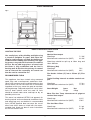
1
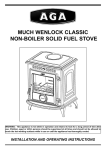
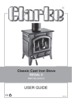
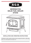
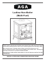
Ludlow Non-Boiler
(Multi-Fuel)
This appliance is hot while in operation and retains its heat for a long period of time after use.
Children, aged or infirm persons should be supervised at all times and should not be allowed
to touch the hot working surfaces while in use or until the appliance has thoroughly cooled.
When using the stove in situations where children, aged and/or infirm persons are
present a fireguard must be used to prevent accidental contact with the stove. The fireguard
should be manufactured in accordance with BS 8423:2002.
WHEN READING THESE INSTRUCTIONS REFER TO THE SECTIONS ON LIGHTING THE FIRE
& REFUELLING
INSTALLATION AND OPERATING INSTRUCTIONS
TABLE OF CONTENTS
PAGE NO.
1.
General . . . . . . . . . . . . . . . . . . . . . . . . . . . . . . . . . . . . . . . . . . . . . . . . . . . . . . . . . . . . . .
2
2.
Pre-Installation Assembly. . . . . . . . . . . . . . . . . . . . . . . . . . . . . . . . . . . . . . . . . . . . . . . . .
2
3.
Flues . . . . . . . . . . . . . . . . . . . . . . . . . . . . . . . . . . . . . . . . . . . . . . . . . . . . . . . . . . . . . . . .
2
4.
Chimney . . . . . . . . . . . . . . . . . . . . . . . . . . . . . . . . . . . . . . . . . . . . . . . . . . . . . . . . . . . . . .
3
5.
Top Flue Exit . . . . . . . . . . . . . . . . . . . . . . . . . . . . . . . . . . . . . . . . . . . . . . . . . . . . . . . . . .
3
6.
Rear Flue Exit . . . . . . . . . . . . . . . . . . . . . . . . . . . . . . . . . . . . . . . . . . . . . . . . . . . . . . . . .
4
7.
Down Draughts . . . . . . . . . . . . . . . . . . . . . . . . . . . . . . . . . . . . . . . . . . . . . . . . . . . . . . . .
4
8.
Ventilation & Combustion Air Requirements . . . . . . . . . . . . . . . . . . . . . . . . . . . . . . . . . .
4
9.
Permanent Air Vent . . . . . . . . . . . . . . . . . . . . . . . . . . . . . . . . . . . . . . . . . . . . . . . . . . . . .
5
Extractor Fan. . . . . . . . . . . . . . . . . . . . . . . . . . . . . . . . . . . . . . . . . . . . . . . . . . . . . .
5
CO Alarms . . . . . . . . . . . . . . . . . . . . . . . . . . . . . . . . . . . . . . . . . . . . . . . . . . . . . . .
5
10.
Commissioning & Handover . . . . . . . . . . . . . . . . . . . . . . . . . . . . . . . . . . . . . . . . . . . . . .
5
11.
Location . . . . . . . . . . . . . . . . . . . . . . . . . . . . . . . . . . . . . . . . . . . . . . . . . . . . . . . . . . . . . .
5
12.
Clearance to Combustibles . . . . . . . . . . . . . . . . . . . . . . . . . . . . . . . . . . . . . . . . . . . . . . .
6
13.
Floor Protection . . . . . . . . . . . . . . . . . . . . . . . . . . . . . . . . . . . . . . . . . . . . . . . . . . . . . . . .
6
14.
Stove Dimensions . . . . . . . . . . . . . . . . . . . . . . . . . . . . . . . . . . . . . . . . . . . . . . . . . . . . . .
7
15.
Lighting the Fire . . . . . . . . . . . . . . . . . . . . . . . . . . . . . . . . . . . . . . . . . . . . . . . . . . . . . . .
7
Outputs . . . . . . . . . . . . . . . . . . . . . . . . . . . . . . . . . . . . . . . . . . . . . . . . . . . . . . . . . . . . . .
7
16.
Operating . . . . . . . . . . . . . . . . . . . . . . . . . . . . . . . . . . . . . . . . . . . . . . . . . . . . . . . . . . . .
8
17.
Primary Air Control Spin Valve . . . . . . . . . . . . . . . . . . . . . . . . . . . . . . . . . . . . . . . . . . . .
8
18.
Secondary Air Control . . . . . . . . . . . . . . . . . . . . . . . . . . . . . . . . . . . . . . . . . . . . . . . . . . .
8
19.
Tertiary Air Control . . . . . . . . . . . . . . . . . . . . . . . . . . . . . . . . . . . . . . . . . . . . . . . . . . . . . .
9
20.
Re-Fuelling . . . . . . . . . . . . . . . . . . . . . . . . . . . . . . . . . . . . . . . . . . . . . . . . . . . . . . . . . . .
9
21.
De-ashing . . . . . . . . . . . . . . . . . . . . . . . . . . . . . . . . . . . . . . . . . . . . . . . . . . . . . . . . . . . .
9
22.
Disposal of Ash . . . . . . . . . . . . . . . . . . . . . . . . . . . . . . . . . . . . . . . . . . . . . . . . . . . . . . . .
9
23.
Maintenance . . . . . . . . . . . . . . . . . . . . . . . . . . . . . . . . . . . . . . . . . . . . . . . . . . . . . . . . . .
10
24.
Chimney Cleaning . . . . . . . . . . . . . . . . . . . . . . . . . . . . . . . . . . . . . . . . . . . . . . . . . . . . . .
10
25.
Fire Safety . . . . . . . . . . . . . . . . . . . . . . . . . . . . . . . . . . . . . . . . . . . . . . . . . . . . . . . . . . . .
10
26.
Important Notes . . . . . . . . . . . . . . . . . . . . . . . . . . . . . . . . . . . . . . . . . . . . . . . . . . . . . . .
11
27.
Lighting . . . . . . . . . . . . . . . . . . . . . . . . . . . . . . . . . . . . . . . . . . . . . . . . . . . . . . . . . . . . . .
11
28.
Glass - Cleaning and Replacement . . . . . . . . . . . . . . . . . . . . . . . . . . . . . . . . . . . . . . . .
11
29.
Summer Shutdown . . . . . . . . . . . . . . . . . . . . . . . . . . . . . . . . . . . . . . . . . . . . . . . . . . . . .
11
30.
Exploded View . . . . . . . . . . . . . . . . . . . . . . . . . . . . . . . . . . . . . . . . . . . . . . . . . . . . . . . .
12
1
LUDLOW (MULTI-FUEL) NON-BOILER STOVE
INSTALLATION & OPERATING INSTRUCTIONS
IMPORTANT WARNING: This stove must not be
installed into a chimney that serves any other
heating appliance. There must not be an extractor fan fitted in the same room as the stove as
this can cause the stove to emit fumes into the
room.
NOTE: Please note that it is a legal requirement
under England & Wales Building Regulations that
the installation of the stove is either carried out
under Local Authority Building Control approval or
is installed by a Competent Person registered with
a Government approved Competent Persons
Scheme. HETAS Ltd operate such a Scheme and
a listing of their Registered Competent Persons
can be found on their website at www.hetas.co.uk.
The installation must be completed in accordance with current National and European
Standards and Local Codes. It should be noted
that the requirements and these publications
may be superseded during the life of this manual.
GENERAL
When installing, operating and maintaining your
stove respect basic standards of fire safety. Read
these instructions carefully before commencing the
installation. Failure to do so may result in damage to
persons or property. Consult your local Municipal
office and your insurance representative to determine what regulations are in force. Save these
instructions for future reference.
PRE-INSTALLATION ASSEMBLY
1. After removing the stove from the packaging,
open the fire door and remove all contents from
inside.
2. Fit the fire door handle using the screw provided.
3. Remove the stove from the pallet and fit the legs.
Take care not to damage the tertiary air control
under the stove base. Position it in the final
installation position (See Location & Clearance to
Combustibles Section).
Special care must be taken when installing the stove
such that the requirements of the Health & Safety at
Work Act are met.
Handling
FLUES
Adequate facilities must be available for loading,
unloading and site handling.
Flues should be vertical wherever possible and
where a bend is necessary, it should not make an
angle of more than 45o with the vertical. Horizontal
flue runs should be avoided except in the case of a
back outlet from the appliance, when the length of
the horizontal section should not exceed 150mm.
Fire Cement
Some types of fire cement are caustic and should
not be allowed to come into contact with the skin. In
case of contact with the skin wash immediately with
plenty of water.
In order to minimise flue resistance and to make
sweeping easier it is recommended to use 2 x 45o
bends rather than a 90o bend.
Asbestos
The flue termination point must be located to minimise any wind effects. Wind effects of suction,
pressure zones and turbulence can be created by
the roof and adjacent objects. Wind effects can also
be created by natural land contours.
This stove contains no asbestos. If there is a possibility of disturbing any asbestos in the course of
installation then please seek guidance and use
appropriate protective equipment.
Metal Parts
To minimise the wind effects, the flue termination
point should be located a minimum of 600mm from
the roof measured vertically and 2300mm measured
horizontally. Where this termination point does not
suffice it may be necessary to extend the flue pipe
so that the termination point is above the apex. See
Fig.1 and 3.
When installing or servicing this stove care should
be taken to avoid the possibility of personal injury.
2
2300
relined using an approved lining system. The stove
must be connected to a chimney with a minimum
continuous draught of 12 Pascal’s (.05” WG). Poor
draught conditions will result in poor performance.
All register plates, restrictor plates, damper etc.,
which could obstruct the flue at a future date should
be removed before connecting this appliance. If connecting to an existing chimney with a flue diameter
of more than 150mm it is necessary to line the flue
using a suitable stainless steel flue liner. Where a
masonry chimney is not available a proprietary type
125 - 150mm twin wall, fully insulated pipe may be
used, of appropriate material.
600
Fig.1
The pipe must terminate at a point no lower than the
main ridge adjacent of outside obstructions. With
such installation, access to the chimney must be
provided for cleaning purposes. (See Fig.1)
When flue piping passes through a closure plate
with a sliding door, ensure that the pipe continues
up and is ultimately connected to the flue liner and
well sealed with fire cement.
Appliance
Soot Door
Any existing chimney must be clear of obstruction
and have been swept clean immediately before
installation of the stove. If the stove is fitted in place
of an open fire then the chimney should be swept
shortly after installation to clear any soot falls which
may have occurred due to the difference in combustion between the stove and the open fire.
CHIMNEY
The stove is a radiant room heater and must be connected to a chimney of the proper size and type.
Refer to BS EN 15287-1:2007, Design Installation
and Commissioning of Chimneys; Part 1: Chimneys
for non-room sealed heating appliances, for guidance.
The main chimney must have a cross sectional area
of at least 176cm2 or a diameter of at least 150mm.
Never connect to a smaller chimney. It is acceptable
to use a length of pipe (125mm diameter) up to
50cm in length from the top flue outlet spigot if
required.
TOP FLUE EXIT
Fig.2
Following that an increaser must be used to
increase the flue/chimney diameter to a minimum of
150mm. For rear outlet connection it is advised to
use an increaser direct from the flue spigot to
increase the flue diameter to a minimum 150mm
diameter.
Do not connect to a chimney serving another appliance. The minimum chimney height, 4.5 meters
from the floor on which the stove is installed.
A flue that has proved to be unsatisfactory, particuarly with regard to down draught should not be used
for venting this appliance until it has been examined
any faults corrected.
An existing masonry chimney should be inspected
and if necessary repaired by a competent mason or
3
Fig.4
For the top flue outlet configuration, remove the
blanking plate from the hob, remove the flue spigot
from the back plate and fix it to the hob. Fix the outlet blanking plate to back plate (see Fig.2). Push the
flue outlet connector pipe (not supplied) into the flue
spigot and cement into place using approved fire
cement, ensuring that no fire cement is blocking the
flue passageway.
Direction of wind
REAR FLUE EXIT
Push the flue connector pipe (not supplied) into the
flue spigot and cement into place using approved
fire cement ensuring that no cement is blocking the
flue passageway.
DOWN DRAUGHTS
Pressure zone
Suction zone
Direction of wind
However well designed, constructed and positioned,
the satisfactory performance of the flue can be
adversely affected by down draught caused by nearby hills, adjacent tall buildings or trees. These can
deflect wind to blow directly down the flue or create
a zone of low pressure over the terminal. A suitable
anti-down draught terminal or cowl will usually effectively combat direct down blow but no cowl is likely
to prevent down draught due to a low pressure zone.
(See Figs. 3 & 4).
Pressure zone
Suction zone
Direction of wind
Fig.3
Pressure zone
Suction zone
VENTILATION AND COMBUSTION AIR
REQUIREMENTS
This appliance is rated at 6.6kw and requires a free
air vent of 8.8cm2. If a flue draught stabiliser is fitted the air requirement is 28.6cm2. When calculating combustion air requirements for this appliance
use the following equation: 550mm2 per each kW of
rated output above 5 kW should be provided, where
a flue draught stabiliser is used the total free area
shall be increased by 300mm2 for each kW of rated
output. If there is another appliance using air fitted
in the same or adjacent room, it will be necessary to
provide an additional air supply.
Pitched roof not exceeding 45o showing external and
internal flues and ridge termination
All materials used in the manufacture of air vents
should be such that the vent is dimensionally stable,
corrosion resistant, and has no provision for closure.
The effective free area of any vent should be ascertained before installation. The effect of any grills
should be allowed for when determining the effective
free area of any vent.
Air vents direct to the outside of the building should
be located so that any air current produced will not
4
pass through normally occuppied areas of the room.
An air vent outside the building should not be located less than the dimensions specified within the
Building Regulations and B.S. 8303: Part 1 from any
part of the flue terminal. These air vents must also
be satisfactorily fire proofed as per Building
Regulations and B.S. 8303: Part 1.
Further guidance on the installation of the
carbon monoxide alarm is available in BS EN
50292: 2002 and from the alarm manufacturer’s
instructions.
Provision of an alarm must not be considered
a substitute for either installing the appliance
correctly or ensuring regular servicing and
maintenance of the appliance and chimney
system.
Air vents in internal walls should not communicate
with bedrooms, bedsits, toilets, bathrooms or room
containing a shower.
COMMISSIONING & HANDOVER
Air vents traversing cavity walls should include a
continuous duct across the cavity. The duct should
be installed in such a manner as not to impair the
weather resistance of the cavity.
On completion of the installation allow a suitable
period of time for any fire cement and mortar to dry
out, when a small fire may be lit and checked to
ensure the smoke and fumes are taken from the
stove up the chimney and emitted safely to theatmosphere. Do not run at full output for at least 24
hours.
Joints between air vents and outside walls should be
sealed to prevent the ingress of moisture. Existing
air vents should be of the correct size and unobstructed for the appliance in use. If there is an
extraction fan fitted in adjacent rooms where this
appliance is fitted, additional air vents may be
required to alleviate the possibility of spillage of
products of combustion from the appliance/flue
while the fan is in operation. Refer to B.S. 8303 Part
1.
On completion of the installation and commissioning
ensure that the operating instructions for the stove
are left with the customer. Ensure to advise the customer on the correct use of the appliance with the
fuels likely to be used on the stove and warn them to
use only the recommended fuels for the stove.
Where such an installation exists, a test for spillage
should be made with the fan or fans and other appliances using air in operation at full rate, (i.e. extraction fans, tumble dryers) with all external doors and
windows closed.
Advise the user what to do should smoke or fumes
be emitted from the stove. The customer should be
warned to use a fire guard to BS 8423:2002 in the
presence of children, aged and/or infirm persons.
LOCATION
If spillage occurs following the above operation, an
additional air vent of sufficient size to prevent this
occurrence should be installed.
There are several conditions to be considered in
selecting a location for your stove.
PERMANENT AIR VENT
A. Position in the area to be heated - central locations are usually best. If situated in an alcove, site
as far forward as possible, to provide more heat
to the room.
B. Allowances for proper clearances to com bustibles.
The stove requires an adequate air supply in order
for it to operate safely and efficiently. The installer
may have fitted a permanent air supply vent into the
room in which the stove is installed to provide combustion and/or ventilation air. This air vent should
not under any circumstances be shut off or sealed.
Extractor Fan
There must not be an extractor fan fitted in the same
room as the stove as this can cause the stove to
emit smoke and fumes into the room.
CO Alarms
Building regulations require that when ever a
new or replacement fixed solid fuel or
wood/biomass appliance is installed in a
dwelling a carbon monoxide alarm must be
fitted in the same room as the appliance.
5
CLEARANCE TO COMBUSTIBLES
It is recommended that this appliance is sited next to
and on a non-combustible surface. A minimum all
round clearance of 100mm will allow air circulation
and not impede the performance of the stove. If it is
necessary to site the stove near to a combustible
surface a minimum clearance of 700mm to side
walls and rear walls must be maintained. The flue
connector may pass through walls or partitions constructed of combustible materials provided the connector is either listed for wall pass-through or is routed through a device listed for wall pass-through and
is installed in accordance with the conditions of the
listing. Any unexposed metal that is used as part of
a wall pass-through system and is exposed to flue
gases shall be constructed of stainless steel or other
equivalent material that will resist corrosion, softening, or cracking from flue gas at temperatures up to
982°C.
FLOOR PROTECTION
It is recommended that this appliance is installed on
a solid, level, non combustible hearth conforming to
current Building Regulations.
6
STOVE DIMENSIONS
Fig.5
LIGHTING THE FIRE
HOW TO OPERATE YOUR STOVE
Outputs
Nominal heat output
Wood logs
Manufactured smokeless fuel (MSF)
Use small pieces of dry kindling and light using
a chemical firelighter or paper. Add extra kindling in small amounts and wait for the flame to
establish before adding more kindling. The lighting process may take 20-30 minutes to establish
the fire. Do not add large pieces of wood until
the flame is fully established and the fuel is
burning well. At this time the primary air control
can be shut and the secondary air control can
then be used to control the fire.
7.1 kW
6.6 kW
Wood logs should be split up to 30cm long and
10cm diameter
Efficiency (Net)
Wood logs
Manufactured smokeless fuel (MSF)
76%
69%
Flue Outlet -125mm (5”) into a 150mm (6”) Flue
Liner
RECOMMENDED FUELS
Typical fuelling intervals to obtain nominal output:
This appliance has been tested using seasoned
wood logs and manufactured smokeless fuels.
Other fuels are commercially available and may give
similar results. Do not use fuels with a Petro-coke
ingredient as this may cause the grate to overheat,
causing damage. Reduced outputs will result when
fuels of lower calorific value are used. All fuels
should be stored under cover and kept as dry as
possible prior to use.
Wood logs
Manufactured smokeless fuel (MSF)
Stove Weight:
Gross
77 kgs
1.5 hrs
1.5 hrs
Net
69kgs
Mean Flue Gas Temp. downstream of spigot at
nominal heat output:
This stove has obtained HETAS Ltd approval for
burning natural and manufactured smokeless fuels
and wood logs only as detailed in recommended
fuels. HETAS Approval does not cover the use of
other fuels either alone or mixed with the recommended fuels listed, nor does it cover instructions
for the use of other fuels.
Wood Logs
Manufactured smokeless fuel (MSF)
313°C
370°C
Flue Gas Mass Flow:
Wood Logs
Manufactured smokeless fuel (MSF)
7
5.1 g/s
6.2 g/s
OPERATING
SECONDARY AIR CONTROL
Check that all controls and catches are operating
correctly and ensure that all flue connections are
thoroughly sealed. Set all air controls to fully open.
Open the secondary air control situated over the
door fully by sliding to the right. The marks situated
nearby are indicators for the amount of opening
ranging from a short bar - less air to a long bar more air. About three quarters open should be a
good guide for normal running.
Primary Air Control - spin wheel (Fig. 6)
Secondary Air Control - slider (Fig. 7)
Tertiary Air Control - slider (Fig. 8)
Fig. 7
The spinwhel on the front will allow additional air into
the fire and should only be used on start up or if a
boost is needed.
To keep smoke emission to a minimum follow
these tips:Add fuel little and often, rather than in large pieces.
As a rough guide the fire will use about 2 kgs of fuel
per hour. Do not over fuel.
Do not allow the bed to become too small before
adding more fuel. It is better to refuel little and often
and keep the fire hot.
PRIMARY AIR CONTROL SPIN VALVE
When burning manufactured smokeless fuels, the
spin valve located near the bottom of the door controls the primary air supply to the stove. For maximum heat output and burn rate rotate the spin valve
fully in an anti-clockwise direction. For a minimum
burn rate rotate the spin valve fully in a clockwise
direction until fully closed. For nominal heat output
the spinwheel will need to be open about 2 turns
depending on the draught conditions of the chimney.
You will soon learn the spin valve settings to best
suit your requirements. The tool supplied fits the
spin valve and is designed to operate this part safely. It also fits the secondary air slide knob. These
parts will become very hot when the stove is in use
and should not be adjusted with an unprotected
hand.
Fig. 6
OPEN
CLOSED
8
TERTIARY AIR CONTROL
Fig.9
When burning wood pull out fully the control knob.
This air control is a push pull operation, pull for fully
open and push for fully closed. The control can be
gradually moved between fully open and fully closed
for the desired setting. Fully open will be the hottest
setting, as this will provide the maximum air to the
fire and will help to clean the glass even after it has
become sooty. This control can be used in conjunction with the spin valve but generally the fire will perform best if the slider is used when burning wood
and the spin valve is used when burning manufactured smokeless fuels. These controls are hot when
the appliance is in use. Use the tool to operate these
controls.
Fig.8
DE-ASHING
Never allow the ashpan to overfill as it will cause
damage to the grate. Open the fire door and remove
ashpan using the operating tool. Close the fire door.
When the ash is disposed of, replace the empty ashpan. (See Fig. 10). Do not leave the fire unattended
with the fire door open, even for a minute.
Fig. 10
RE-FUELLING
When burning wood the requirement to riddle the
fire is much less. Do not riddle the fire with the spinwheel open but fully open the secondary air control
instead.
DISPOSAL OF ASH
Ashes should be placed in a metal container with a
tight fitting lid. The closed container of ashes should
be on a non-combustible floor or on the ground well
away from all combustible materials pending final
disposal. If the ashes are disposed of by burial in soil
or otherwise locally dispersed they should be
retained in the closed container until all cinders have
thoroughly cooled.
9
MAINTENANCE
FIRE SAFETY
CREOSOTE: Formation and Need for Removal
When some fuels are burned slowly, they produce
tar and other organic vapours, which combine with
expelled moisture to form creosote. The creosote
vapours condense in the relatively cool chimney flue
of a slow-burning fire. As a result, creosote residue
accumulates on the flue lining. When ignited creosote makes an extremely hot fire.
To provide reasonable fire safety the following
should be given serious consideration:
1. The installation of smoke detectors.
2. A conveniently located fire extinguisher to contend with small fires resulting from burning
embers.
3. A practical evacuation plan.
4. A plan to deal with a chimney fire as follows:
CHIMNEY CLEANING
a.
b.
Notify the fire department.
Prepare occupants for immediate evacuation.
Close all openings into the stove.
While awaiting the fire department watch for
ignition to adjacent combustibles from over
head stove pipe or from embers or from
sparks from the chimney.
Chimney and connector should be cleaned at least
twice a year. Once before heating season and once
after. The chimney connector and chimney should
be inspected at least monthly during the heating
season to determine if a creosote build-up has
occurred. Remove the cast iron baffle plate located
at the top end of the firebricks before chimney cleaning.
IMPORTANT NOTES
When inspecting a masonry chimney, start at the
cleanout door, normally found at the base of the
chimney, or on the outside. If your chimney does not
have a clean-out door one should be provided.
Now that your Ludlow Stove is installed and no
doubt you are looking forward to many comforts it
will provide, we would like to give you some tips on
how to get the best results from your stove.
WARNING NOTE
Properly installed, operated and maintained this
stove will not emit fumes into the dwelling.
Occasional fumes from de-ashing and re-fuelling
may occur. However, persistent fume emission is
potentially dangerous and must not be tolerated. if
fume emission does persist, then the following
immediate action should be taken:
1. We would like if you could take some time to
read the operating instructions/hints, which we
are confident, will be of great benefit to you.
c.
d.
2. Do not burn fuel with a high moisture content,
such as a damp peat or unseasoned timber.
This will only result in a build up of tar in the
stove and in the chimney and the possibility of a
chimney fire.
(a) Open doors and windows to ventilate the room
and then leave the premises.
(b) Let the fire go out.
(c) Check for flue or chimney blockage and
clean if required.
(d) Do not attempt to relight the fire until the
cause of the fume emission has been identified and corrected. If necessary seek expert
advice.
3. CLEAN THE FLUE-WAYS OF THE STOVE
EVERY WEEK AND ENSURE THAT THERE
ARE NO BLOCKAGES. CHECK FLUEWAYS
BEFORE LIGHTING ESPECIALLY AFTER A
SHUT-DOWN PERIOD. PLEASE REFER TO
MANUAL FOR INSTRUCTIONS.
4. Do not allow the fire to die down too much
before adding fresh fuel. Riddling is not always
necessary when wood burning.
CO ALARM
5. Never allow a build up of ashes in the ash pan,
as this may cause the grate to burn out prematurely.
Your installer should have fitted a CO alarm in the
same room as the appliance. If the alarm sounds
unexpectedly, follow the instructions given under
“Warning Note” above.
6. Avoid long periods of slow burning of damp or
unseasoned fuel as this will result in tarring flueways and chimney i.e. timber.
The most common cause of fume emission is flueway or chimney blockage. For your own safety
these must be kept clean at all times.
7. Allow adequate air ventilation to ensure plenty
of air for combustion.
8. Do not burn rubbish/house hold plastic.
10
5. Never use inflammable liquid i.e. gasoline, petrol
paraffin etc. to start or freshen up a fire in this
heater.
9. Clean the chimney at least twice a year.
10. Keep all combustible materials a safe distance
away from the appliance, please see section for
clearances to combustibles.
6. When the fire is well established add fuel to the
firebox. Adjust to the desired setting the spin
valve and / or the secondary air slide depending
on the fuel burned. (See Re-Fuelling Section).
11. For safety reasons never leave children or the
elderly unaccompanied while stove is in use.
Use a fireguard.
7. To shut the fire down, do not add fuel. Make
sure that the fire door is properly closed, that the
spin valve is firmly shut and the secondary air
slide is pushed in. Cutting off the air supply will
reduce the heat output.
GLASS
12. Avoid contact with appliance when in use as the
stove reaches very high operating temperatures.
13. This appliance should be regularly maintained
by a competent service engineer. Use only
replacement parts recommended by AGA Using
unauthorised parts will invalidate your guaran
tee and may cause damage or injury.
1. How to clean:
The glass will clean itself when there is sufficient
heat generated by burning fuel. If a build-up of creosote occurs on the glass it may be due to draft conditions, poor quality fuel or very slow burning for
along time. Only clean glass when the stove is thoroughly cooled. Clean with a liquid detergent taking
care not to scratch the glass.
14. Do not use an aerosol spray on or near the
stove when it is alight.
AN ODOUR WILL EMIT FROM STOVE ON FIRST
FIRING, WHEN FIRE REACHES MAXIMUM
TEMPERATURE OVER A NUMBER OF HOURS
THIS ODOUR WILL SUBSIDE.
IT IS BEST ADVISED TO OPEN WINDOWS DURING THIS PERIOD.
2. Glass Replacement: (See Fig.11)
a. Open the door fully.
b. Remove the four corner screws and clips and
carefully remove the broken glass.
c. Clean the glass recess in the door.
d. Attach adhesive thermal tape to the perimeter of
the replacement glass.
e. Place the thermal tape side of the glass into the
door recess and replace the four corner clips.
f. Tighten screws.
g. Replace glass only with ceramic glass 5mm thick.
THIS ODOUR IS UNPLEASANT BUT NOT
TOXIC. YOU MAY WISH TO VACATE THE ROOM
WHILE THE PAINT CURES.
Before lighting the stove check with the installer
that the installation work and commissioning
checks described in the installation instructions
have been carried out correctly and that the
chimney has been swept clean, is sound and free
from any obstructions. As part of the stoves
commissioning and handover the installer
should demonstrate how to operate the stove
correctly.
Fig.11
LIGHTING
IMPORTANT: The first few fires should be relatively small to permit the refractory to set properly and to season the stove.
1. Before lighting the stove, ensure that any buildup in the firebox has been removed and that the
ashpan has been emptied.
2. Open secondary air control by sliding to the
right.
SUMMER SHUTDOWN
3. Lay a few crumpled sheets of paper on the grate
and then a few small sticks, kindling or an
approved firelighter.
For summer shutdown of the stove, ensure all ashes
have been cleaned from the ash compartment and
that the air control is fully open, to avoid condensation in the stove firebox and possible corrosion during this shutdown period.
4. Ignite and close the door.
11
LUDLOW (MULTI-FUEL) STOVE EXPLODED VIEW
1.
2.
3.
4.
5.
6.
7.
8.
9.
10.
11.
12.
13.
14.
15.
16.
17.
18.
RATING PLATE BRACKET
DATA PLAQUE
AIR WASH CONTROL LEVER
AIR WASH COVER
AIR WASH SHUTTER
ASHPAN
BACK
BACK AIR DAMPER
BACK BRICK
BASE
BLANKING PLATE
BLANKING PLATE LOCKING BAR
BRACKET
DAMPER PULL ROD
DOOR HANDLE AXLE
FIRE BED
FIRE DOOR
FIRE FENCE
19.
20.
21.
22.
23.
24.
25.
26.
27.
28.
29.
30.
31.
32.
33.
34.
35.
FRONT FRAME
GLASS CLIP
GRATE
HOB
LEG
LHS PANEL
LOWER BAFFLE
MIDDLE BAFFLE
PULL ROD BRACKET
PULL ROD KNOB
RH SIDE PANEL
RHS BRICK
RIDDLING ROD
SPIGOT
SPINVALVE
SPRING HANDLE ASSY
TOP BAFFLE
AGA,
Station Road,
Ketley, Telford,
Shropshire, TF1 5AQ,
UK
12
N00613AXX
131007