1
pÅêÉÉåmolJff»
rëÉêÛë=dìáÇÉ
•
•
Manual # 26-0407000-00
Revision B
pÅêÉÉåmolJff»=√=rëÉêÛë=dìáÇÉ
`çéóêáÖÜí
© Barco, Inc. December 5, 2005
All rights reserved. No part of this document may be copied, reproduced or translated. It
shall not otherwise be recorded, transmitted or stored in a retrieval system without the prior
written consent of Barco.
kçíáÅÉ
Barco provides this manual “as is” without warranty of any kind, either expressed or
implied, including but not limited to the implied warranties or merchantability and fitness for
a particular purpose. Barco may make improvements and/or changes to the product(s) and/
or the program(s) described in this publication at any time without notice.
This publication could contain technical inaccuracies or typographical errors. Changes are
periodically made to the information in this publication; these changes are incorporated in
new editions of this publication.
cÉÇÉê~ä=`çããìåáÅ~íáçåë=`çããáëëáçå=Ec``F=pí~íÉãÉåí
This equipment has been tested and found to comply with the limits for a class A digital
device, pursuant to Part 15 of the FCC rules. These limits are designed to provide
reasonable protection against harmful interference when the equipment is operated in a
commercial environment. This equipment generates, uses, and can radiate radio frequency
energy and, if not installed and used in accordance with the instruction manual, may cause
harmful interference to radio communications. Operation of this equipment in a residential
area may cause harmful interference, in which case the user will be responsible for
correcting any interference.
dì~ê~åíÉÉ=~åÇ=`çãéÉåë~íáçå
Barco provides a guarantee relating to perfect manufacturing as part of the legally
stipulated terms of guarantee. On receipt, the purchaser must immediately inspect all
delivered goods for damage incurred during transport, as well as for material and
manufacturing faults Barco must be informed immediately in writing of any complaints.
The period of guarantee begins on the date of transfer of risks, in the case of special
systems and software on the date of commissioning, at latest 30 days after the transfer of
risks. In the event of justified notice of compliant, Barco can repair the fault or provide a
replacement at its own discretion within an appropriate period. If this measure proves to be
impossible or unsuccessful, the purchaser can demand a reduction in the purchase price or
cancellation of the contract. All other claims, in particular those relating to compensation for
direct or indirect damage, and also damage attributed to the operation of software as well
as to other services provided by Barco, being a component of the system or independent
service, will be deemed invalid provided the damage is not proven to be attributed to the
absence of properties guaranteed in writing or due to the intent or gross negligence or part
of Barco.
If the purchaser or a third party carries out modifications or repairs on goods delivered by
Barco, or if the goods are handled incorrectly, in particular if the systems are commissioned
operated incorrectly or if, after the transfer of risks, the goods are subject to influences not
ii
ScreenPRO-II • User’s Guide
agreed upon in the contract, all guarantee claims of the purchaser will be rendered invalid.
Not included in the guarantee coverage are system failures which are attributed to
programs or special electronic circuitry provided by the purchaser, e.g. interfaces. Normal
wear as well as normal maintenance are not subject to the guarantee provided by Barco
either.
The environmental conditions as well as the servicing and maintenance regulations
specified in this manual must be complied with by the customer.
qê~ÇÉã~êâë
Brand and product names mentioned in this manual may be trademarks, registered
trademarks or copyrights of their respective holders. All brand and product names
mentioned in this manual serve as comments or examples and are not to be understood as
advertising for the products or their manufactures.
`çãé~åó=^ÇÇêÉëë
Barco Events USA
11101 Trade Center Drive
Rancho Cordova, California 95670
USA
•
•
•
Phone: (916) 859-2500
Fax: (916) 859-2515
Websites:
~
~
www.folsom.com
www.events.barco.com
Barco N.V.
Noordlaan 5
8520 Kuurne
BELGIUM
•
•
•
Phone: +32 56.36.82.11
Fax: +32 56.35.16.51
Website: www.barco.com
ScreenPRO-II • User’s Guide
iii
léÉê~íçêë=p~ÑÉíó=pìãã~êó
The general safety information in this summary is for operating personnel.
aç=kçí=oÉãçîÉ=`çîÉêë=çê=m~åÉäë
There are no user-serviceable parts within the unit. Removal of the top cover will expose
dangerous voltages. To avoid personal injury, do not remove the top cover. Do not operate
the unit without the cover installed.
mçïÉê=pçìêÅÉ
This product is intended to operate from a power source that will not apply more than 230
volts rms between the supply conductors or between both supply conductor and ground. A
protective ground connection by way of grounding conductor in the power cord is essential
for safe operation.
dêçìåÇáåÖ=íÜÉ=mêçÇìÅí
This product is grounded through the grounding conductor of the power cord. To avoid
electrical shock, plug the power cord into a properly wired receptacle before connecting to
the product input or output terminals. A protective-ground connection by way of the
grounding conductor in the power cord is essential for safe operation.
rëÉ=íÜÉ=mêçéÉê=mçïÉê=`çêÇ
Use only the power cord and connector specified for your product. Use only a power cord
that is in good condition. Refer cord and connector changes to qualified service personnel.
rëÉ=íÜÉ=mêçéÉê=cìëÉ
To avoid fire hazard, use only the fuse having identical type, voltage rating, and current
rating characteristics. Refer fuse replacement to qualified service personnel.
aç=kçí=léÉê~íÉ=áå=bñéäçëáîÉ=^íãçëéÜÉêÉë
To avoid explosion, do not operate this product in an explosive atmosphere.
iv
ScreenPRO-II • User’s Guide
qÉêãë=få=qÜáë=j~åì~ä=~åÇ=bèìáéãÉåí=j~êâáåÖ=
t^okfkd
Highlights an operating procedure, practice, condition, statement, etc., which, if not strictly
observed, could result in injury to or death of personnel.
Note
Highlights an essential operating procedure, condition or
statement.
`^rqflk
The exclamation point within an equilateral triangle is intended to alert the user to the
presence of important operating and maintenance (servicing) instructions in the literature
accompanying the appliance.
^sboqfppbjbkq>
Le point d´exclamation dans un triangle equilatéral signale à alerter l´utilisateur qu´il y a
des instructions d´operation et d´entretien tres importantes dans la litérature qui
accompagne l´appareil.
slopf`eq
Ein Ausrufungszeichen innerhalb eines gleichwinkeligen Dreiecks dient dazu, den
Benutzer auf wichtige Bedienungs-und Wartungsanweisungen in der Dem Great
beiliegenden Literatur aufmerksam zu machen.
ScreenPRO-II • User’s Guide
v
`Ü~åÖÉ=eáëíçêó
The table below lists the changes to the ScreenPRO-II User’s Guide.
Table 0-1. Change History
Rev
Date
ECO #
Description
Approved By
A
9/23/05
1491
New ScreenPRO-II User’s Guide
Andreas Yerocostas
B
12/5/05
1527
Updated Appendix A, “Input/Output Resolutions List”;
added Appendices C and D; plus other misc. corrections.
Andreas Yerocostas
vi
ScreenPRO-II • User’s Guide
q~ÄäÉ=çÑ=`çåíÉåíë
`Ü~éíÉê=N
fåíêçÇìÅíáçå =K=K=K=K=K=K=K=K=K=K=K=K=K=K=K=K=K=K=K=K=K=K=K=K=K=K=K=K=K=K=K=K=K=K=K=K=K=K=K=K=K=K= N
Chapter Structure . . . . . . . . . . . . . . . . . . . . . . . . . . . . . . . . . . . . . . . . . . . . . . .
How to Use This Guide. . . . . . . . . . . . . . . . . . . . . . . . . . . . . . . . . . . . . . . . . . .
Navigating . . . . . . . . . . . . . . . . . . . . . . . . . . . . . . . . . . . . . . . . . . . . . . .
Table of Contents and Index . . . . . . . . . . . . . . . . . . . . . . . . . . . . . . . . .
Conventions . . . . . . . . . . . . . . . . . . . . . . . . . . . . . . . . . . . . . . . . . . . . . . . . . . .
Terms and Definitions. . . . . . . . . . . . . . . . . . . . . . . . . . . . . . . . . . . . . . . . . . . .
System Overview . . . . . . . . . . . . . . . . . . . . . . . . . . . . . . . . . . . . . . . . . . . . . . .
ScreenPRO-II High-Resolution Seamless Switcher . . . . . . . . . . . . . . .
ScreenPRO-II Features . . . . . . . . . . . . . . . . . . . . . . . . . . . . . . . . . . . . .
Product Models . . . . . . . . . . . . . . . . . . . . . . . . . . . . . . . . . . . . . . . . . . .
Multiple Screen User Interface (Optional) . . . . . . . . . . . . . . . . . . . . . . .
A Word About Layers. . . . . . . . . . . . . . . . . . . . . . . . . . . . . . . . . . . . . . .
Effect Combinations. . . . . . . . . . . . . . . . . . . . . . . . . . . . . . . . . . . . . . . .
Mixer Effect 1 . . . . . . . . . . . . . . . . . . . . . . . . . . . . . . . . . . . . .
Mixer Effect 2 . . . . . . . . . . . . . . . . . . . . . . . . . . . . . . . . . . . . .
Mixer Effect 3 . . . . . . . . . . . . . . . . . . . . . . . . . . . . . . . . . . . . .
Mixer Effect 4 . . . . . . . . . . . . . . . . . . . . . . . . . . . . . . . . . . . . .
Mixer Effect 5 . . . . . . . . . . . . . . . . . . . . . . . . . . . . . . . . . . . . .
Mixer Effect 6 . . . . . . . . . . . . . . . . . . . . . . . . . . . . . . . . . . . . .
`Ü~éíÉê=O
e~êÇï~êÉ=lêáÉåí~íáçå =K=K=K=K=K=K=K=K=K=K=K=K=K=K=K=K=K=K=K=K=K=K=K=K=K=K=K=K=K=K=K=K=NN
In This Chapter . . . . . . . . . . . . . . . . . . . . . . . . . . . . . . . . . . . . . . . . . . . . . . . .
ScreenPRO-II Rear Panel . . . . . . . . . . . . . . . . . . . . . . . . . . . . . . . . . . . . . . .
Analog Input Flexibility. . . . . . . . . . . . . . . . . . . . . . . . . . . . . . . . . . . . .
ScreenPRO-II Front Panel . . . . . . . . . . . . . . . . . . . . . . . . . . . . . . . . . . . . . . .
Use of Color . . . . . . . . . . . . . . . . . . . . . . . . . . . . . . . . . . . . . . . . . . . . . . . . . .
Front Panel Sections . . . . . . . . . . . . . . . . . . . . . . . . . . . . . . . . . . . . . . . . . . .
Touch Screen Menu Section . . . . . . . . . . . . . . . . . . . . . . . . . . . . . . . .
Source Selection Bus . . . . . . . . . . . . . . . . . . . . . . . . . . . . . . . . . . . . .
Layer Control Section . . . . . . . . . . . . . . . . . . . . . . . . . . . . . . . . . . . . .
Transition Section . . . . . . . . . . . . . . . . . . . . . . . . . . . . . . . . . . . . . . . .
Mixer Functions Section . . . . . . . . . . . . . . . . . . . . . . . . . . . . . . . . . . .
`Ü~éíÉê=P
1
2
2
2
2
3
4
4
4
5
6
6
7
7
8
8
8
9
9
11
12
14
15
17
18
19
20
21
23
24
e~êÇï~êÉ=fåëí~ää~íáçå=K=K=K=K=K=K=K=K=K=K=K=K=K=K=K=K=K=K=K=K=K=K=K=K=K=K=K=K=K=K=K=K=OT
In This Chapter . . . . . . . . . . . . . . . . . . . . . . . . . . . . . . . . . . . . . . . . . . . . . . . .
Safety Precautions . . . . . . . . . . . . . . . . . . . . . . . . . . . . . . . . . . . . . . . . . . . . .
Unpacking and Inspection . . . . . . . . . . . . . . . . . . . . . . . . . . . . . . . . . . . . . . .
Site Preparation . . . . . . . . . . . . . . . . . . . . . . . . . . . . . . . . . . . . . . . . . . . . . . .
Rack-Mount Installation . . . . . . . . . . . . . . . . . . . . . . . . . . . . . . . . . . . . . . . . .
Cable and Adapter Information. . . . . . . . . . . . . . . . . . . . . . . . . . . . . . . . . . . .
ScreenPRO-II • User’s Guide
27
28
28
28
28
29
vii
Table of Contents
Input Connection Chart. . . . . . . . . . . . . . . . . . . . . . . . . . . . . . . . . . . . . . . . . . 30
Installation . . . . . . . . . . . . . . . . . . . . . . . . . . . . . . . . . . . . . . . . . . . . . . . . . . . 32
`Ü~éíÉê=Q
jÉåì=lêáÉåí~íáçå=K=K=K=K=K=K=K=K=K=K=K=K=K=K=K=K=K=K=K=K=K=K=K=K=K=K=K=K=K=K=K=K=K=K=K=K=PR
In This Chapter . . . . . . . . . . . . . . . . . . . . . . . . . . . . . . . . . . . . . . . . . . . . . . . .
Home Menu . . . . . . . . . . . . . . . . . . . . . . . . . . . . . . . . . . . . . . . . . . . . . . . . . .
Global Rules . . . . . . . . . . . . . . . . . . . . . . . . . . . . . . . . . . . . . . . . . . . .
Input Menu . . . . . . . . . . . . . . . . . . . . . . . . . . . . . . . . . . . . . . . . . . . . . . . . . . .
Input Menu Tree . . . . . . . . . . . . . . . . . . . . . . . . . . . . . . . . . . . . . . . . .
Input Menu Description . . . . . . . . . . . . . . . . . . . . . . . . . . . . . . . . . . . .
Input Menu Functions . . . . . . . . . . . . . . . . . . . . . . . . . . . . . . . . . . . . .
Input Pre and Sub Menus . . . . . . . . . . . . . . . . . . . . . . . . . . . . . . . . . .
Input Acquisition Menu . . . . . . . . . . . . . . . . . . . . . . . . . . . . .
Input Configuration Menu . . . . . . . . . . . . . . . . . . . . . . . . . . .
Sizing Menu. . . . . . . . . . . . . . . . . . . . . . . . . . . . . . . . . . . . . .
Color Balance Menu . . . . . . . . . . . . . . . . . . . . . . . . . . . . . . .
Aspect Ratio Menu . . . . . . . . . . . . . . . . . . . . . . . . . . . . . . . .
Output Menu. . . . . . . . . . . . . . . . . . . . . . . . . . . . . . . . . . . . . . . . . . . . . . . . . .
Output Menu Tree . . . . . . . . . . . . . . . . . . . . . . . . . . . . . . . . . . . . . . . .
Output Menu Description . . . . . . . . . . . . . . . . . . . . . . . . . . . . . . . . . . .
Output Menu Functions . . . . . . . . . . . . . . . . . . . . . . . . . . . . . . . . . . . .
Output Sub Menus . . . . . . . . . . . . . . . . . . . . . . . . . . . . . . . . . . . . . . . .
Settings Menu . . . . . . . . . . . . . . . . . . . . . . . . . . . . . . . . . . . .
Genlock Menu . . . . . . . . . . . . . . . . . . . . . . . . . . . . . . . . . . . .
Test Pattern Menu. . . . . . . . . . . . . . . . . . . . . . . . . . . . . . . . .
System Menu . . . . . . . . . . . . . . . . . . . . . . . . . . . . . . . . . . . . . . . . . . . . . . . . .
System Menu Tree . . . . . . . . . . . . . . . . . . . . . . . . . . . . . . . . . . . . . . .
System Menu Description . . . . . . . . . . . . . . . . . . . . . . . . . . . . . . . . . .
System Menu Functions . . . . . . . . . . . . . . . . . . . . . . . . . . . . . . . . . . .
System Sub Menus . . . . . . . . . . . . . . . . . . . . . . . . . . . . . . . . . . . . . . .
Diagnostics Setup Menu . . . . . . . . . . . . . . . . . . . . . . . . . . . .
Reset Menu . . . . . . . . . . . . . . . . . . . . . . . . . . . . . . . . . . . . . .
Software Version Menu . . . . . . . . . . . . . . . . . . . . . . . . . . . . .
Serial 1 Port Setup Menu . . . . . . . . . . . . . . . . . . . . . . . . . . .
EDID DVI Input Format Menu . . . . . . . . . . . . . . . . . . . . . . . .
Technical Support Menu . . . . . . . . . . . . . . . . . . . . . . . . . . . .
Effects Menu. . . . . . . . . . . . . . . . . . . . . . . . . . . . . . . . . . . . . . . . . . . . . . . . . .
Status Menu . . . . . . . . . . . . . . . . . . . . . . . . . . . . . . . . . . . . . . . . . . . . . . . . . .
Display Settings Menu . . . . . . . . . . . . . . . . . . . . . . . . . . . . . . . . . . . . . . . . . .
Keypad Backlight Menu . . . . . . . . . . . . . . . . . . . . . . . . . . . . . . . . . . . .
PIP Adjustment Menu . . . . . . . . . . . . . . . . . . . . . . . . . . . . . . . . . . . . . . . . . . .
PIP Adjustment Menu Tree . . . . . . . . . . . . . . . . . . . . . . . . . . . . . . . . .
PIP Adjustment Menu Description . . . . . . . . . . . . . . . . . . . . . . . . . . . .
PIP Adjustment Menu Functions . . . . . . . . . . . . . . . . . . . . . . . . . . . . .
PIP Functions . . . . . . . . . . . . . . . . . . . . . . . . . . . . . . . . . . . .
PIP Adjustment Sub Menus . . . . . . . . . . . . . . . . . . . . . . . . . . . . . . . . .
Border Menu . . . . . . . . . . . . . . . . . . . . . . . . . . . . . . . . . . . . .
Crop Menu. . . . . . . . . . . . . . . . . . . . . . . . . . . . . . . . . . . . . . .
Shadow Menu . . . . . . . . . . . . . . . . . . . . . . . . . . . . . . . . . . . .
Image Effects Menu . . . . . . . . . . . . . . . . . . . . . . . . . . . . . . .
Key Menu . . . . . . . . . . . . . . . . . . . . . . . . . . . . . . . . . . . . . . . . . . . . . . . . . . . .
viii
35
36
36
37
37
38
38
40
41
42
43
45
46
47
47
48
48
49
49
50
51
52
52
53
53
55
55
58
59
60
61
62
63
64
65
66
67
67
68
68
69
69
70
71
72
73
75
ScreenPRO-II • User’s Guide
Table of Contents
Key Menu Tree . . . . . . . . . . . . . . . . . . . . . . . . . . . . . . . . . . . . . . . . . .
Key Menu Description . . . . . . . . . . . . . . . . . . . . . . . . . . . . . . . . . . . . .
Key Menu Functions . . . . . . . . . . . . . . . . . . . . . . . . . . . . . . . . . . . . . .
Key Sub Menus . . . . . . . . . . . . . . . . . . . . . . . . . . . . . . . . . . . . . . . . . .
Matte Menu . . . . . . . . . . . . . . . . . . . . . . . . . . . . . . . . . . . . . .
Key Adjustment Menu . . . . . . . . . . . . . . . . . . . . . . . . . . . . . .
Input Source Adjustment Menu . . . . . . . . . . . . . . . . . . . . . . . . . . . . . . . . . . .
Input Source Adjustment Menu Tree . . . . . . . . . . . . . . . . . . . . . . . . . .
Input Source Adjustment Menu Description . . . . . . . . . . . . . . . . . . . .
Input Source Adjustment Menu Functions. . . . . . . . . . . . . . . . . . . . . .
Background Input Setup Menu . . . . . . . . . . . . . . . . . . . . . . . . . . . . . . . . . . . .
Background Input Setup Menu Tree . . . . . . . . . . . . . . . . . . . . . . . . . .
Background Input Setup Menu Description . . . . . . . . . . . . . . . . . . . . .
Background Input Setup Menu Functions . . . . . . . . . . . . . . . . . . . . . .
Background Matte Menu . . . . . . . . . . . . . . . . . . . . . . . . . . . .
Frame Grab Menu . . . . . . . . . . . . . . . . . . . . . . . . . . . . . . . . . . . . . . . . . . . . .
DSK Adjustment Menu . . . . . . . . . . . . . . . . . . . . . . . . . . . . . . . . . . . . . . . . . .
DSK Adjustment Menu Tree . . . . . . . . . . . . . . . . . . . . . . . . . . . . . . . .
DSK Adjustment Menu Description . . . . . . . . . . . . . . . . . . . . . . . . . . .
DSK Adjustment Menu Functions . . . . . . . . . . . . . . . . . . . . . . . . . . . .
DSK Input Setup Menu . . . . . . . . . . . . . . . . . . . . . . . . . . . . .
DSK Matte Adjustment Menu . . . . . . . . . . . . . . . . . . . . . . . .
LOGO Input Setup Menu . . . . . . . . . . . . . . . . . . . . . . . . . . . . . . . . . . . . . . . .
Remote Control Menu . . . . . . . . . . . . . . . . . . . . . . . . . . . . . . . . . . . . . . . . . .
`Ü~éíÉê=R
75
76
76
77
78
79
81
81
82
82
84
84
85
85
87
88
90
90
91
91
92
94
95
96
póëíÉã=pÉíìéK=K=K=K=K=K=K=K=K=K=K=K=K=K=K=K=K=K=K=K=K=K=K=K=K=K=K=K=K=K=K=K=K=K=K=K=K=K=K=K=VV
In This Chapter . . . . . . . . . . . . . . . . . . . . . . . . . . . . . . . . . . . . . . . . . . . . . . . . 99
Setup Prerequisites . . . . . . . . . . . . . . . . . . . . . . . . . . . . . . . . . . . . . . . . . . . 100
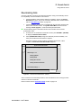
Return to Factory Default . . . . . . . . . . . . . . . . . . . . . . . . . . . . . . . . . . . . . . . 101
Touch Screen Calibration . . . . . . . . . . . . . . . . . . . . . . . . . . . . . . . . . . . . . . . 101
Output Setup . . . . . . . . . . . . . . . . . . . . . . . . . . . . . . . . . . . . . . . . . . . . . . . . 102
Projector Setup. . . . . . . . . . . . . . . . . . . . . . . . . . . . . . . . . . . . . . . . . . . . . . . 102
Quick Input Setup Procedure . . . . . . . . . . . . . . . . . . . . . . . . . . . . . . . . . . . . 103
Comprehensive Input Setup . . . . . . . . . . . . . . . . . . . . . . . . . . . . . . . . . . . . . 104
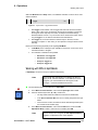
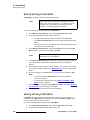
Setting up Backgrounds . . . . . . . . . . . . . . . . . . . . . . . . . . . . . . . . . . . . . . . . 107
Programming EDID . . . . . . . . . . . . . . . . . . . . . . . . . . . . . . . . . . . . . . 107
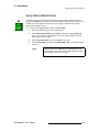
Using A Matte Color as a Background. . . . . . . . . . . . . . . . . . . . . . . . 108
Using a DVI Input as a Background or DSK . . . . . . . . . . . . . . . . . . . 109
Using a Still Frame as a Background . . . . . . . . . . . . . . . . . . . . . . . . 110
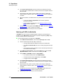
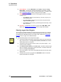
Setting up the DSK . . . . . . . . . . . . . . . . . . . . . . . . . . . . . . . . . . . . . . . . . . . . 111
Using a DVI Input as the DSK . . . . . . . . . . . . . . . . . . . . . . . . . . . . . . 111
Using a Still Frame as the DSK . . . . . . . . . . . . . . . . . . . . . . . . . . . . . 112
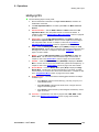
Setting up the LOGO . . . . . . . . . . . . . . . . . . . . . . . . . . . . . . . . . . . . . . . . . . 113
Saving the Setup . . . . . . . . . . . . . . . . . . . . . . . . . . . . . . . . . . . . . . . . . . . . . 113
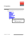
`Ü~éíÉê=S
léÉê~íáçåë =K=K=K=K=K=K=K=K=K=K=K=K=K=K=K=K=K=K=K=K=K=K=K=K=K=K=K=K=K=K=K=K=K=K=K=K=K=K=K=K=KNNR
In This Chapter . . . . . . . . . . . . . . . . . . . . . . . . . . . . . . . . . . . . . . . . . . . . . . .
Prerequisites. . . . . . . . . . . . . . . . . . . . . . . . . . . . . . . . . . . . . . . . . . . . . . . . .
Operational Configuration. . . . . . . . . . . . . . . . . . . . . . . . . . . . . . . . . . . . . . .
Monitor Layout . . . . . . . . . . . . . . . . . . . . . . . . . . . . . . . . . . . . . . . . . .
ScreenPRO-II • User’s Guide
115
116
117
117
ix
Table of Contents
Touch Screen Calibration . . . . . . . . . . . . . . . . . . . . . . . . . . . . . . . . .
Lookahead Preview . . . . . . . . . . . . . . . . . . . . . . . . . . . . . . . . . . . . . .
Understanding Raster Boxes . . . . . . . . . . . . . . . . . . . . . . . . . . . . . . .
A Word About LOS . . . . . . . . . . . . . . . . . . . . . . . . . . . . . . . . . . . . . .
Working with Layers . . . . . . . . . . . . . . . . . . . . . . . . . . . . . . . . . . . . . . . . . . .
Switching Sources . . . . . . . . . . . . . . . . . . . . . . . . . . . . . . . . . . . . . . .
Background Transitions . . . . . . . . . . . . . . . . . . . . . . . . . . . . . . . . . . .
Understanding Split and Mix Modes . . . . . . . . . . . . . . . . . . . . . . . . .
Split Mode . . . . . . . . . . . . . . . . . . . . . . . . . . . . . . . . . . . . . .
Mix Mode. . . . . . . . . . . . . . . . . . . . . . . . . . . . . . . . . . . . . . .
Working with PIPs in Split Mode . . . . . . . . . . . . . . . . . . . . . . . . . . . .
Working with PIPs in Mix Mode . . . . . . . . . . . . . . . . . . . . . . . . . . . . .
Modifying PIPs . . . . . . . . . . . . . . . . . . . . . . . . . . . . . . . . . . . . . . . . . .
Working with Keys in Split Mode . . . . . . . . . . . . . . . . . . . . . . . . . . . .
Working with Keys in Mix Mode. . . . . . . . . . . . . . . . . . . . . . . . . . . . .
Modifying Keys . . . . . . . . . . . . . . . . . . . . . . . . . . . . . . . . . . . . . . . . .
Clearing Layers from Program. . . . . . . . . . . . . . . . . . . . . . . . . . . . . .
Working with Layer Functions . . . . . . . . . . . . . . . . . . . . . . . . . . . . . . . . . . .
Changing the Layer Mode . . . . . . . . . . . . . . . . . . . . . . . . . . . . . . . . .
Using Full Screen . . . . . . . . . . . . . . . . . . . . . . . . . . . . . . . . . . . . . . .
Using Swap Z-Order . . . . . . . . . . . . . . . . . . . . . . . . . . . . . . . . . . . . .
Using Freeze . . . . . . . . . . . . . . . . . . . . . . . . . . . . . . . . . . . . . . . . . . .
Using Reset . . . . . . . . . . . . . . . . . . . . . . . . . . . . . . . . . . . . . . . . . . . .
Using LOGO as Black Preview . . . . . . . . . . . . . . . . . . . . . . . . . . . . .
Using Move. . . . . . . . . . . . . . . . . . . . . . . . . . . . . . . . . . . . . . . . . . . . . . . . . .
Programming Moves . . . . . . . . . . . . . . . . . . . . . . . . . . . . . . . . . . . . .
Program Move on Preview Method . . . . . . . . . . . . . . . . . . .
Program Move on Program Method . . . . . . . . . . . . . . . . . .
Pending and Triggering Moves . . . . . . . . . . . . . . . . . . . . . . . . . . . . .
Pend on Preview Method . . . . . . . . . . . . . . . . . . . . . . . . . .
Pend on Program Method . . . . . . . . . . . . . . . . . . . . . . . . . .
Move Notes . . . . . . . . . . . . . . . . . . . . . . . . . . . . . . . . . . . . . . . . . . . .
Working with Transitions . . . . . . . . . . . . . . . . . . . . . . . . . . . . . . . . . . . . . . .
Modifying Layers On Program . . . . . . . . . . . . . . . . . . . . . . . . . . . . . . . . . . .
Capturing Still Frames . . . . . . . . . . . . . . . . . . . . . . . . . . . . . . . . . . . . . . . . .
Still Frame Capture Overview . . . . . . . . . . . . . . . . . . . . . . . . . . . . . .
Capturing Still Frames from a Background Input . . . . . . . . . . . . . . . .
Capturing Still Frames from a Layer . . . . . . . . . . . . . . . . . . . . . . . . .
Saving Still Frames in Permanent Memory . . . . . . . . . . . . . . . . . . . .
^ééÉåÇáñ=^=
péÉÅáÑáÅ~íáçåëK=K=K=K=K=K=K=K=K=K=K=K=K=K=K=K=K=K=K=K=K=K=K=K=K=K=K=K=K=K=K=K=K=K=K=K=K=K=KNQN
In This Appendix. . . . . . . . . . . . . . . . . . . . . . . . . . . . . . . . . . . . . . . . . . . . . .
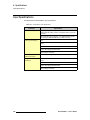
Input Specifications . . . . . . . . . . . . . . . . . . . . . . . . . . . . . . . . . . . . . . . . . . .
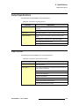
Output Specifications . . . . . . . . . . . . . . . . . . . . . . . . . . . . . . . . . . . . . . . . . .
User Control . . . . . . . . . . . . . . . . . . . . . . . . . . . . . . . . . . . . . . . . . . . . . . . . .
Physical and Electrical Specifications . . . . . . . . . . . . . . . . . . . . . . . . . . . . .
Communications Specifications . . . . . . . . . . . . . . . . . . . . . . . . . . . . . . . . . .
Pinouts . . . . . . . . . . . . . . . . . . . . . . . . . . . . . . . . . . . . . . . . . . . . . . . . . . . . .
DVI Connector Pinouts . . . . . . . . . . . . . . . . . . . . . . . . . . . . . . . . . . .
Analog 15-pin D Connector . . . . . . . . . . . . . . . . . . . . . . . . . . . . . . . .
x
117
118
119
119
120
120
121
122
122
122
123
124
125
126
126
127
128
129
129
129
129
130
130
131
132
132
132
133
133
133
134
134
135
136
137
137
137
138
139
141
142
143
143
144
144
145
145
146
ScreenPRO-II • User’s Guide
Table of Contents
Ethernet Connector . . . . . . . . . . . . . . . . . . . . . . . . . . . . . . . . . . . . . . 147
Serial Connector . . . . . . . . . . . . . . . . . . . . . . . . . . . . . . . . . . . . . . . . 148
Input and Output Resolutions . . . . . . . . . . . . . . . . . . . . . . . . . . . . . . . . . . . . 149
^ééÉåÇáñ=_=
`çåí~Åí=fåÑçêã~íáçå=K=K=K=K=K=K=K=K=K=K=K=K=K=K=K=K=K=K=K=K=K=K=K=K=K=K=K=K=K=K=K=K=KNRP
In This Appendix. . . . . . . . . . . . . . . . . . . . . . . . . . . . . . . . . . . . . . . . . . . . . .
Warranty . . . . . . . . . . . . . . . . . . . . . . . . . . . . . . . . . . . . . . . . . . . . . . . . . . . .
Return Material Authorization (RMA) . . . . . . . . . . . . . . . . . . . . . . . . . . . . . .
Contact Information . . . . . . . . . . . . . . . . . . . . . . . . . . . . . . . . . . . . . . . . . . .
^ééÉåÇáñ=`=
réÖê~ÇáåÖ=pçÑíï~êÉK=K=K=K=K=K=K=K=K=K=K=K=K=K=K=K=K=K=K=K=K=K=K=K=K=K=K=K=K=K=K=K=KNRR
In This Appendix. . . . . . . . . . . . . . . . . . . . . . . . . . . . . . . . . . . . . . . . . . . . . .
Software Upgrade Overview. . . . . . . . . . . . . . . . . . . . . . . . . . . . . . . . . . . . .
Serial Upgrade Method. . . . . . . . . . . . . . . . . . . . . . . . . . . . . . . . . . . . . . . . .
Ethernet Upgrade Method . . . . . . . . . . . . . . . . . . . . . . . . . . . . . . . . . . . . . .
Troubleshooting Ethernet Communications. . . . . . . . . . . . . . . . . . . .
^ééÉåÇáñ=a=
155
156
156
159
165
oÉãçíÉ=`çåíêçä=K=K=K=K=K=K=K=K=K=K=K=K=K=K=K=K=K=K=K=K=K=K=K=K=K=K=K=K=K=K=K=K=K=K=K=K=KNST
In This Appendix. . . . . . . . . . . . . . . . . . . . . . . . . . . . . . . . . . . . . . . . . . . . . .
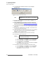
Using Remote Control . . . . . . . . . . . . . . . . . . . . . . . . . . . . . . . . . . . . . . . . .
System Connection . . . . . . . . . . . . . . . . . . . . . . . . . . . . . . . . . . . . . .
Internal Router Configuration . . . . . . . . . . . . . . . . . . . . . . .
External Serial Router Configuration . . . . . . . . . . . . . . . . . .
External Ethernet Router Configuration . . . . . . . . . . . . . . .
External Serial and Ethernet Router Configuration . . . . . . .
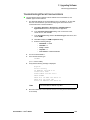
Setting Unique ScreenPRO-II IDs . . . . . . . . . . . . . . . . . . . . . . . . . . .
Enabling Remote Control. . . . . . . . . . . . . . . . . . . . . . . . . . . . . . . . . .
Downloading Code . . . . . . . . . . . . . . . . . . . . . . . . . . . . . . . . . . . . . .
Destination Setup . . . . . . . . . . . . . . . . . . . . . . . . . . . . . . . . . . . . . . .
Router Setup . . . . . . . . . . . . . . . . . . . . . . . . . . . . . . . . . . . . . . . . . . .
Output Patching . . . . . . . . . . . . . . . . . . . . . . . . . . . . . . . . . . . . . . . . .
Input Patching . . . . . . . . . . . . . . . . . . . . . . . . . . . . . . . . . . . . . . . . . .
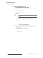
Disabling Remote Control . . . . . . . . . . . . . . . . . . . . . . . . . . . . . . . . .
Remote Control Caveats and Capabilities . . . . . . . . . . . . . . . . . . . . .
fåÇÉñ
153
153
153
154
167
168
168
169
170
172
174
175
176
177
178
179
181
182
184
184
=K=K=K=K=K=K=K=K=K=K=K=K=K=K=K=K=K=K=K=K=K=K=K=K=K=K=K=K=K=K=K=K=K=K=K=K=K=K=K=K=K=K=K=K=K=K=K=K=K=K=K=KNUR
ScreenPRO-II • User’s Guide
xi
Table of Contents
xii
ScreenPRO-II • User’s Guide
NK==fåíêçÇìÅíáçå
This chapter is designed to introduce you to the ScreenPRO-II. Areas to be covered are:
•
•
•
•
•
Chapter Structure
How to Use This Guide
Conventions
Terms and Definitions
System Overview
`Ü~éíÉê=píêìÅíìêÉ
The following chapters provide instructions for all aspects of ScreenPRO-II operations:
•
Chapter 1, “Introduction” provides a system overview, a list of features, and
discusses easy ways to use this guide.
•
Chapter 2, “Hardware Orientation” explains the ScreenPRO-II’s front and rear
panels in detail.
•
Chapter 3, “Hardware Installation” provides comprehensive system installation
instructions.
•
Chapter 4, “Menu Orientation” explains the system’s configuration, setup and
adjustment menus, and provides basic menu “navigation” procedures.
•
Chapter 5, “System Setup” outlines procedures for setting up and configuring the
ScreenPRO-II.
•
•
Chapter 6, “Operations” provides basic system operating instructions.
Appendix A, “Specifications” lists the ScreenPRO-II’s input, output, video,
mechanical and power specifications, and includes connector pinouts.
•
Appendix B, “Contact Information” lists important contact, RMA, warranty and
technical support details.
•
Appendix C, “Upgrading Software” provides a detailed procedure for upgrading
ScreenPRO-II software.
•
Appendix D, “Remote Control” outlines the steps required when ScreenPRO-II is
connected to an external controller, such as Encore.
ScreenPRO-II • User’s Guide
1
NK==fåíêçÇìÅíáçå
How to Use This Guide
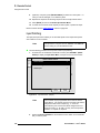
eçï=íç=rëÉ=qÜáë=dìáÇÉ
Following are important tips for streamlining your use of this User’s Guide in its electronic
“PDF” form.
k~îáÖ~íáåÖ
Use Acrobat Reader’s “bookmarks” to navigate to the desired location. All chapter files
have the same bookmark structure for instant navigation to any section. Please note:
•
•
Extensive hyperlinks are provided within the chapters.
•
Use the “Previous Page” and “Next Page” buttons to go to the previous or next
page within a file.
•
Use Acrobat’s extensive search capabilities, such as the “Find” tool and “Search
Index” tool to perform comprehensive searches as required.
Use Acrobat’s “Go to Previous View” and “Return to Next View” buttons to trace
your complete navigational path.
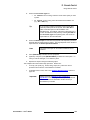
q~ÄäÉ=çÑ=`çåíÉåíë=~åÇ=fåÇÉñ
Use the Table of Contents bookmarks to navigate a desired topic. Click any item to
instantly jump to that section of the guide. You can also use the Index to jump to specific
topics within a chapter. Each page number in the Index is a hyperlink.
`çåîÉåíáçåë=
The following conventions are used throughout this guide:
•
•
•
The symbol denotes an operations procedure.
The symbol S denotes an example.
Entries written in bold-face letters denote physical buttons or rear chassis
connectors.
S Press Split Layer to ...
•
When two buttons together are required for an operation or function, the plus (+)
sign is used between the buttons. This procedure requires that you hold down the
first button, then press the second.
•
Button labels on the Touch Screen menus are shown in bold uppercase letters
between braces.
S Press {BORDER} to …
•
When a sequence of menu selections is required to complete a given procedure,
the ">" symbol is used to divide each successive menu picks.
S To access the Genlock Menu, press {HOME} > {OUTPUT} >
{GLCK}.
2
ScreenPRO-II • User’s Guide
NK==fåíêçÇìÅíáçå
Terms and Definitions
qÉêãë=~åÇ=aÉÑáåáíáçåë
The following terms and definitions are used throughout this guide:
•
A “Background” is an unscaled source, typically originating from a computer.
ScreenPRO-II enables you to work with two background sources, each of which
appears at the system’s lowest priority — visually in back of all other sources.
•
•
The abbreviation “BG” is also used throughout this guide for Background.
•
A “Layer” is an image display element (such as a PIP, Key or Background) that
has an associated visual priority — either in front (or in back) of another layer.
•
A “LOGO” is a full screen image that is selected from one of three still frames that
you can capture with ScreenPRO-II.
•
A “Mixer” is the electronic circuitry that enables you to transition (and scale) PIPs
and Keys over a background.
•
“M/E” (Mix/Effects) is synonymous with “mixer.” ScreenPRO-II has one internal
M/E, capable of layering either two PIPs, two keys, or one of each.
•
•
“Operator” refers to the person who uses the system.
•
•
•
“Screen” and “Menu” both refer to the Touch Screen menus.
A “Key” is an electronic (and visual) process whereby one image is electronically
superimposed over another source or background. Keys are typically used for
titles, logos and banners.
“PIP” refers to Picture-in-Picture, an on-screen setup in which one picture
(typically of reduced size) is positioned over another background image — or
another PIP. PIPs can be reduced, enlarged, bordered, shadowed, and mixed on
and off Program. PIPs can overlap each other, depending on their visual priority.
“System” refers to the ScreenPRO-II.
A “Scaler” is the electronic circuitry that enables you to reduce or enlarge source
images, thus creating PIPs and Keys that can be positioned (and transitioned).
ScreenPRO-II • User’s Guide
3
NK==fåíêçÇìÅíáçå
System Overview
póëíÉã=lîÉêîáÉï
The following topics are discussed in this section:
•
•
•
•
•
•
ScreenPRO-II High-Resolution Seamless Switcher
ScreenPRO-II Features
Product Models
Multiple Screen User Interface (Optional)
A Word About Layers
Effect Combinations
pÅêÉÉåmolJff eáÖÜJoÉëçäìíáçå=pÉ~ãäÉëë=pïáíÅÜÉê
The ScreenPRO-II Seamless Switcher is a high-resolution multi-layer video display system
that combines seamless switching with a variety of creative video effects. The result is a
versatile video production tool for live event staging and fixed installation applications.
ScreenPRO-II uses five image layers to produce sophisticated effects, including
transitioning backgrounds, transitioning PIPs, wipes, dissolves and keys.
The five ScreenPRO-II layers are:
•
•
•
•
One unscaled background
Two scaled inputs
One unscaled downstream key
One LOGO
Using the mixer’s two scaled inputs, you can mix within a PIP, or you can display two
independent PIPs (or Keys) over a background. In addition, two unscaled high-resolution
input channels enable you to transition seamlessly between background images, or
alternately, to use one high-resolution background plus a high-resolution DSK. A LOGO is
also available as a full screen source, using still frames captured from the background
inputs or from the layers.
pÅêÉÉåmolJff=cÉ~íìêÉë
Following is a detailed list of ScreenPRO-II features:
4
•
•
•
•
•
Support for input and output resolutions up to UXGA
•
Internal 8 x 2 analog video router for selecting scaler inputs, plus (on the HD
model), internal 2 x 2 HD-SDI/SD-SDI router.
•
Native high resolution DSK channel, independent of PIP/KEY processing
channels
High quality motion adaptive de-interlacing on SD and HD sources
Low video processing delay, less than 3 input fields
3RU rack-mount chassis
Native high-resolution background channels independent of the PIP/Key
processing channels
ScreenPRO-II • User’s Guide
NK==fåíêçÇìÅíáçå
System Overview
•
PIP effects:
~
~
~
•
•
•
•
Adjustable PIP aspect ratio
PIP borders, including drop shadows and soft edge
Transitioning PIP or Key on a transitioning background
Numerous mix and wipe effects
Programmable matte
Keying
~
~
~
•
PIP size from 1/8 to 8x source resolution
Luminance key
Split key (key alpha and fill)
Color key
Video Processing
~
~
~
~
~
~
10-bit processing
1:1 pixel sampling
Motion adaptive de-interlacing (SD & HD)
3:2 and 2:2 pull down detect
Image cropping
Aspect ratio correction
•
•
Z-order control (priority layers) for overlapping PIPs or Keys
•
•
•
Three assignable, internal frame stores
The mixer layer is dynamically re-assignable as a mixing (transitioning) PIP, or as
two individual (SPLIT) non-transitioning PIPs or Keys
Lookahead preview
Output synchronization: free-run or vertically locked to NTSC/PAL black burst,
CSync or HD tri-level sync
mêçÇìÅí=jçÇÉäë
ScreenPRO-II is available in two different models:
•
Basic Model
The basic model includes eight analog inputs on HD-15 connectors. These inputs
feed an internal 8 x 2 router, which provides sources to the two scalers. The unit
also features two high resolution DVI inputs which can be used for two unscaled
background sources, or one background and one DSK source.
•
HD Model
The HD model is identical to the standard model, with the addition of two HD-SDI/
SD-SDI inputs on BNC connectors. These inputs feed an internal 2 x 2 router,
which provides these additional sources to the two scalers.
ScreenPRO-II • User’s Guide
5
NK==fåíêçÇìÅíáçå
System Overview
jìäíáéäÉ=pÅêÉÉå=rëÉê=fåíÉêÑ~ÅÉ=Eléíáçå~äF
Event control is available using multiple ScreenPRO-II units in conjunction with the Encore
SC/LC Controller or the ScreenPRO-II Controller. In this mode, all ScreenPRO-II functions
(including system setup) are supported from the controller, which is equipped with easy-touse menus, a T-Bar for manual transitions and buttons for user presets.
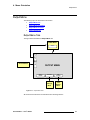
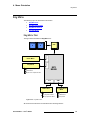
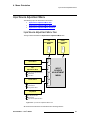
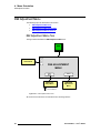
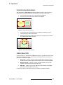
^=tçêÇ=^Äçìí=i~óÉêë
ScreenPRO-II is a five layer system, as illustrated below:
Background
Mixer Layer A
Mixer Layer B
DSK
LOGO
Figure 1-1. ScreenPRO-II Layers
A layer is defined as an image display element (such as a background, PIP, or Key) with an
associated visual priority. The mixer itself has two layers, A and B. For complete flexibility,
each mixer layer can be assigned to either PIP or Key functionality.
A typical ScreenPRO-II application is illustrated below.
Background
PIP
Nature
Key
DSK
Wilderness
Figure 1-2. Layer Illustration — Background, Mixer and DSK
Please note the following important points:
6
•
The full screen LOGO is the highest priority layer. This image visually appears
“over” all other images, including backgrounds, PIPs, keys and the DSK.
•
The Downstream Key (DSK) is the second highest priority layer. It visually
appears over all PIPs, keys and backgrounds — but it is “under” the LOGO.
ScreenPRO-II • User’s Guide
NK==fåíêçÇìÅíáçå
System Overview
•
The high resolution Background layer has the lowest priority. This layer visually
appears “behind” all other PIPs, keys, and the DSK. The system can transition
between two background sources — both of which must be at native projector
resolution.
•
A PIP layer appears “over” backgrounds and “under” the DSK and LOGO. Effects
include mixes and wipes, linear moves and resizing, adjustable aspect ratio,
borders, drop shadows and soft edges.
•
A Key layer also appears “over” backgrounds and “under” the DSK and LOGO.
Key effects include luminance keys, split keys (key alpha and fill), reverse key
(key on background), and color key (graphics).
•
Within the mixer, layer B has priority over layer A, but you can change that priority
as desired with the Swap Z-Order button.
•
Up to eight analog inputs and up to two SD/HD SDI inputs can be scaled to
produce PIP or Key images.
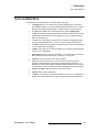
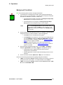
bÑÑÉÅí=`çãÄáå~íáçåë
This section illustrates the many (but not all) combinations of image effects that you can
create on the ScreenPRO-II. Please note:
•
In the following illustrations, the specific layers used in creating each effect are
labeled (e.g., PIP A, PIP B).
•
The symbol ↔ denotes a PIP or a key that can transition. For example, PIP A ↔
B indicates that you can dissolve between sources within the PIP.
The ScreenPRO-II system provides two backgrounds, two scalable layers in the mixer plus
an unscaled DSK and a full screen, unscaled LOGO. The LOGO, DSK and backgrounds
are always unscaled.
Important
If the DSK is in use, the background cannot transition
between A and B. This occurs because BG/DSK Input B is
shared between the DSK and BG B.
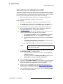
jáñÉê=bÑÑÉÅí=N
This effect includes a non-transitioning background (either A or B), one transitioning PIP
and the DSK.
Background
PIP
A↔B
DSK
Figure 1-3. Effect 1 Diagram
ScreenPRO-II • User’s Guide
7
NK==fåíêçÇìÅíáçå
System Overview
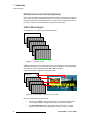
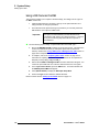
jáñÉê=bÑÑÉÅí=O
This transition is similar to effect 1, but because the DSK is not in use, the background can
transition from source A to B, and the PIP can transition between layers A and B.
Background A
↔B
PIP
A↔B
Figure 1-4. Effect 2 Diagram
jáñÉê=bÑÑÉÅí=P
In this effect, because the DSK is in use, the background cannot transition — you can only
use background A. Here, you can independently fade (or cut) one scaled PIP and one
scaled key, with complete size and position flexibility.
Background A
PIP
A
Key B
DSK
Figure 1-5. Effect 3 Diagram
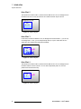
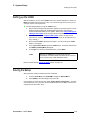
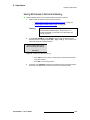
jáñÉê=bÑÑÉÅí=Q
This transition is similar to effect 3, but because the DSK is not in use, the background can
transition between sources A and B. You can also independently fade, cut, size and
position both the PIP and the key.
Background A
PIP
A
↔B
Key B
Figure 1-6. Effect 4 Diagram
8
ScreenPRO-II • User’s Guide
NK==fåíêçÇìÅíáçå
System Overview
jáñÉê=bÑÑÉÅí=R
In this effect, because the DSK is in use, the background cannot transition — you can only
use background A. Here, you can independently fade two scaled PIPs up and down —
with or without the DSK on screen.
Background A
PIP
A
PIP
B
DSK
Figure 1-7. Effect 5 Diagram
jáñÉê=bÑÑÉÅí=S
This transition is similar to effect 5, but because the DSK is not in use, the background can
transition. You can also independently fade the two PIPs.
Background A
PIP
A
↔B
PIP
B
Figure 1-8. Effect 6 Diagram
ScreenPRO-II • User’s Guide
9
NK==fåíêçÇìÅíáçå
System Overview
10
ScreenPRO-II • User’s Guide
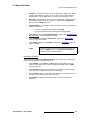
OK==e~êÇï~êÉ=lêáÉåí~íáçå
få=qÜáë=`Ü~éíÉê
This chapter provides detailed information about the ScreenPRO-II’s hardware. The
following topics are discussed:
•
•
•
•
ScreenPRO-II Rear Panel
ScreenPRO-II Front Panel
Use of Color
Front Panel Sections
ScreenPRO-II • User’s Guide
11
2. Hardware Orientation
ScreenPRO-II Rear Panel
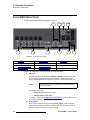
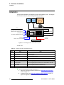
pÅêÉÉåmolJff=oÉ~ê=m~åÉä
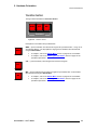
The figure below illustrates the ScreenPRO-II rear panel:
7
1
2
8
3
9
10
4
5
6
Figure 2-1. ScreenPRO-II Rear Panel
1)
SDI Inputs
5)
Preview Output
9)
Serial Ports
2)
Analog Inputs
6)
AC Connector
10)
Ethernet Port
3)
Background/DSK Inputs
7)
Genlock Connectors
4)
Program Outputs
8)
Termination Switch
Following are descriptions of each rear panel connector and section.
1)
SDI Inputs
Two BNC connectors are provided for HD-SDI or SD-SDI inputs (or one of each).
These numbered inputs feed the system’s internal 2 x 2 SDI router, and are
directly associated with the two SDI source buttons on the front panel’s top row.
Note
These connectors are populated only on the HD version of
the ScreenPRO-II.
These inputs will accept:
~
~
SDI (SMPTE 259M-C, NTSC or PAL)
HD-SDI (SMPTE 292M, HDTV).
In Chapter 5, refer to the “Comprehensive Input Setup” section on page 104 for
input setup instructions.
2)
Analog Inputs
Eight 15-pin D connectors are provided for Analog Inputs. These numbered
inputs feed the system’s internal 8 x 2 analog router, and correspond directly to
the eight analog source buttons on the front panel.
12
ScreenPRO-II • User’s Guide
2. Hardware Orientation
ScreenPRO-II Rear Panel
Please note:
3)
~
In Appendix A, refer to the “Analog 15-pin D Connector” section on
page 146 for pinout details.
~
Refer to the “Analog Input Flexibility” section on page 14 for additional
information about each analog input connector.
Background/DSK Inputs
Two DVI connectors are provided for Background and DSK Inputs. Both
connectors are digital only, and do not include analog pins. Please note:
~
To use two background sources, connect one source to connector A and
one to connector B.
~
To use one background and one DSK source, connect the background to
connector A and the DSK source to connector B.
In Appendix A, refer to the “DVI Connector Pinouts” section on page 145 for
pinout details.
4)
Program Outputs
Three connectors are provided for Program Outputs — one DVI and two analog.
5)
~
One DVI connector is provided for the Digital Program Output. This
output is designed for a digital connection to your projector. The output
is digital only, and does not include analog pins. In Appendix A, refer to
the “DVI Connector Pinouts” section on page 145 for pinout details.
~
Two 15-pin D connectors are provided for Analog Program Outputs.
These outputs (identical in content to the digital output) are designed for
analog connections to your projector or to analog monitoring. In
Appendix A, see the “Analog 15-pin D Connector” section on page 146
for pinouts.
Preview Output
One 15-pin D connector is provided for the Analog Preview Output. This output
is designed for an analog connection to your preview monitor. In Appendix A, see
the “Analog 15-pin D Connector” section on page 146 for pinouts.
6)
AC Connector
One AC Connector is provided to connect the ScreenPRO-II to your facility’s AC
power source. The integral switch turns the chassis on and off.
7)
Genlock Connectors
Two BNC connectors are provided for analog Genlock (reference video)
connections. A genlock connection is highly recommended in ScreenPRO-II
configurations that utilize video camera sources. Please note:
~
To genlock the chassis, connect a PAL or NTSC black burst or composite
sync signal to the Genlock In connector.
~
If you are looping reference video to another chassis in your system,
connect a BNC cable from the Genlock Loop connector to the next
device’s Genlock In connector.
~
If this ScreenPRO-II chassis is the last device in a reference video chain,
do not make any connections to the Genlock Loop connector.
ScreenPRO-II • User’s Guide
13
2. Hardware Orientation
ScreenPRO-II Rear Panel
8)
Termination Switch
One recessed switch is provided for switching the genlock termination.
Note
ScreenPRO-II units are shipped from the factory with the
Termination Switch in the “terminated” (75 Ohms) position.
User feedback for the current switch position is provided on the system’s Genlock
Menu. Please note:
9)
~
Use the “terminated” setting (75 Ohms) if the ScreenPRO-II chassis is
the last device in a reference video chain.
~
Use the “high impedance” setting (Hi-Z) if you are looping reference
video to another chassis in your system.
Serial Ports
Two 9-pin D connectors are provided for RS-232 serial communications with the
ScreenPRO-II chassis and for downloading code in the field. In Appendix A, refer
to the “Serial Connector” section on page 148 for pinout details.
10) Ethernet Port
One RJ-45 connector is provided for 10/100BaseT Ethernet communications with
the ScreenPRO-II chassis. When (optionally) connecting the ScreenPRO-II to an
Encore or ScreenPRO-II controller, a standard Ethernet hub or switch on an
isolated network is recommended. The Ethernet connector is compatible with:
~
~
Standard RJ-45 Ethernet cables
Neutrik EtherCon® series cables
In Appendix A, refer to the “Ethernet Connector” section on page 147 for pinout
details.
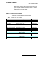
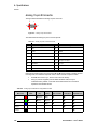
^å~äçÖ=fåéìí=cäÉñáÄáäáíó
Each analog input connector accepts a variety of analog formats including VGA, lowresolution composite video, S-video and YUV component video.
•
•
For RGB with H and V sync, use the VGA connector directly.
Using a VGA to 5xBNC breakout cable, five input combinations are possible.
Cells with check marks denote the connections required for the indicated format.
Table 2-1. Analog Input Combinations using Breakout Cable
Breakout Cable
Wire Color
Composite
Video
R
G
B
H Sync
V Sync
14
3
S-Video
(Y/C)
YUV
(YPbPr)
RGB
Sync on Green
RGB
Comp Sync
RGB
Separate H V
3 (Chrom)
3 (Pr)
3
3
3
3 (Lum)
3 (Lum)
3
3
3
3 (Pb)
3
3
3
3
3
3
ScreenPRO-II • User’s Guide
2. Hardware Orientation
ScreenPRO-II Front Panel
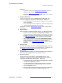
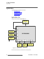
pÅêÉÉåmolJff=cêçåí=m~åÉä
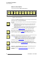
The figure below illustrates the ScreenPRO-II front panel:
1
4
3
2
5
7
6
Figure 2-1. ScreenPRO-II Front Panel
1)
Chassis Handles
4)
Layer Control Section
2)
Touch Screen Menu Section
5)
Transition Section
3)
Source Selection Bus
6)
Mixer Functions Section
7)
ScreenPRO-II Model
Following are descriptions of each front panel control feature:
1)
Chassis Handles
Two Chassis Handles are provided for ease of installation and transportation.
2)
Touch Screen Menu Section
The Touch Screen Menu Section is used for system configuration, setup and
operational adjustments, such as PIPs and keys. Refer to the “Touch Screen
Menu Section” heading on page 19 for details.
3)
Source Selection Bus
The Source Selection Bus allows you to choose the sources that are routed into
PIPs and keys.
~
~
On the basic model, up to 8 analog sources can be routed.
On the HD model, up to 8 analog sources plus up to two HD-SDI/SD-SDI
sources can be routed.
Refer to the “Source Selection Bus” section on page 20 for details.
4)
Layer Control Section
The Layer Control Section is the operational heart of the ScreenPRO-II,
enabling you to assign sources to PIPs and keys on the mixer. Here, you control
the overall “look” on Preview and Program. Refer to the “Layer Control Section”
heading on page 21 for details.
ScreenPRO-II • User’s Guide
15
2. Hardware Orientation
ScreenPRO-II Front Panel
5)
Transition Section
The Transition Section includes three dedicated buttons used for cutting, mixing
and wiping sources on and off Program. Refer to the “Transition Section”
heading on page 23 for details.
6)
Mixer Functions Section
When a layer is active (and blinking) in the Layer Control Section, all buttons in
the Mixer Functions Section apply to that layer, enabling you to change its mode
and manipulate the source. Refer to the “Mixer Functions Section” heading on
page 24 for details.
7)
ScreenPRO-II Model
This section displays the ScreenPRO-II model, either basic or HD.
Figure 2-2. ScreenPRO-II Model Labels
16
ScreenPRO-II • User’s Guide
2. Hardware Orientation
Use of Color
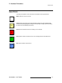
rëÉ=çÑ=`çäçê
Color plays an important “visual” role with the ScreenPRO-II’s front panel buttons:
White buttons are used for sources.
1
PIP
Yellow buttons are functions and modes that always apply to the active (blinking) layer.
Functions include assigning PIPs and keys to the active layer, setting up moves, freezing
the active layer and swapping layer priority.
Red buttons are transition functions, including cut, mix and wipe.
MIX
Green buttons indicate unscaled sources, such as backgrounds and the DSK source.
BG
A
Blue buttons indicate scaled sources.
LAYER
A
ScreenPRO-II • User’s Guide
17
2. Hardware Orientation
Front Panel Sections
cêçåí=m~åÉä=pÉÅíáçåë
This section provides detailed descriptions and illustrations of each front panel section.
The following topics are discussed:
•
•
•
•
•
18
Touch Screen Menu Section
Source Selection Bus
Layer Control Section
Transition Section
Mixer Functions Section
ScreenPRO-II • User’s Guide
2. Hardware Orientation
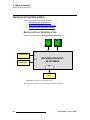
Front Panel Sections
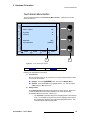
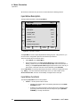
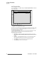
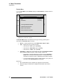
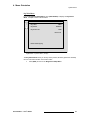
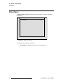
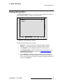
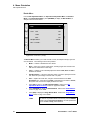
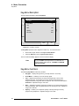
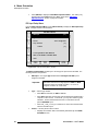
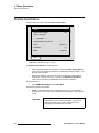
qçìÅÜ=pÅêÉÉå=jÉåì=pÉÅíáçå
The figure below illustrates the Touch Screen Menu Section. A sample menu is also
shown for reference.
PIP ADJUSTMENT
H
O
M
E
S
R
C
H Size < 37.3% >
674
V Size < 58.9% >
452
H Position
-34
V Position
70
S
I
Z
E
H
B
O
R
D
E
R
Move Rate
[ 2.0 ]
Key Frame Effect
P
O
S
[ LINEAR ]
V
C
R
O
P
P
O
S
TRACK
H SIZE
V SIZE
RATE
1
2
Figure 2-3. Touch Screen Menu Section
1)
Touch Screen
2)
Rotary Knobs
Following are descriptions of each area:
1)
Touch Screen
All menus and functions can be accessed by touching the desired label or button
on the Touch Screen itself.
S Example: Press the {BORDER} button to access the Border Menu.
S Example: Press the V Size line to highlight that line. You can now adjust
V Size using the ADJ rotary knob.
2)
Rotary Knobs
Three Rotary Knobs are provided to the right of the Touch Screen. Each knob
controls or adjusts the function that is labeled on the Touch Screen itself,
immediately adjacent to the knob. Please note:
~
ScreenPRO-II • User’s Guide
The Top Knob is generally assigned to navigating fields on the selected
menu. For example, turning the knob moves a highlight up and down a
list of parameters, allowing you to adjust the highlighted function. This
knob also adjusts adjacent parameters.
19
2. Hardware Orientation
Front Panel Sections
~
The Middle and Bottom knobs are generally assigned to adjusting the
adjacent parameters, as labeled on the Touch Screen.
There is no Enter button. If you adjust a value with the
knobs, that function or value is immediately active in Preview.
Note
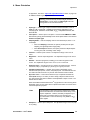
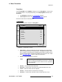
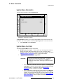
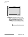
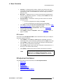
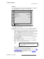
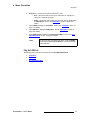
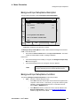
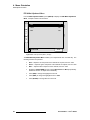
pçìêÅÉ=pÉäÉÅíáçå=_ìë
The figure below illustrates the Source Selection Bus.
Source Selection
Program
1
2
3
4
5
6
7
8
SDI
1
SDI
2
Figure 2-4. Source Selection Bus
Each button represents an input that you can assign to a PIP or key.
•
•
Buttons 1 through 8 correspond to the eight analog inputs on the rear panel.
The two SDI buttons correspond to SDI inputs 1 and 2 on the rear panel. These
buttons are only labeled (and active) with the HD model of ScreenPRO-II.
Press a button in the section to assign the source to the blinking “mixer” button in the Layer
Control Section. When the button is lit and blinking, the source is on Preview, and is
active for manipulation as the PIP or key source on that layer.
1
20
•
When a source button lit solid, the source is on Preview — but it is not active for
manipulation.
•
•
When the Red LED above a source button is lit, the source is on Program.
•
In Chapter 5, refer to the “Comprehensive Input Setup” section on page 104 for
details on all source setup procedures.
Multiple sources can appear on Program and Preview simultaneously, but only
one button can be blinking and active for modification on Preview.
ScreenPRO-II • User’s Guide
2. Hardware Orientation
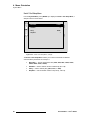
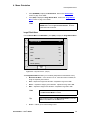
Front Panel Sections
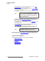
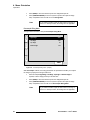
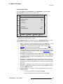
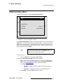
i~óÉê=`çåíêçä=pÉÅíáçå
The figure below illustrates the Layer Control Section.
Program
BG
A
BG
B
LAYER
A
Background
LAYER
B
DSK
LOGO
Mixer
Figure 2-5. Layer Control Section
The buttons in the Layer Control Section enable you to select (on Preview) the sources
that will transition to or from Program — including backgrounds, individual layers, the DSK
and the full screen LOGO.
When you select a blue “layer” button, you are electronically selecting a scaler that you
want to assign as a PIP or key, or modify in some manner. In this way, you control the
overall look on Preview before you “transition” that look to Program.
Please note the following important points:
•
•
Two background sources, one DSK, and one full screen LOGO are provided.
•
Any combination of backgrounds, layers, DSK and LOGO can be selected on
Preview for transition to or from Program.
The buttons are arranged left-to-right in order of visual priority — from the
backgrounds (at the lowest priority) to the LOGO (at the highest visual priority).
Note
The only restriction is that BG B and the DSK are mutually
exclusive. This occurs because the BG/DSK Input B is
shared between the DSK and BG B.
Following are descriptions of each button’s function.
Important
ScreenPRO-II uses a “lookahead” Preview monitor that fully
represents how the Program output will appear next. By
selecting combinations of PIPs, keys, backgrounds and the
DSK, you are composing a Preview image that will appear on
Program — after the next transition. A “lit” button does not
necessarily mean that the source will transition on or off — it
simply means that it is part of the “look” on Preview.
Background Buttons — press to select an unscaled background on Preview for transition
to or from Program. The button lights when selected. Please note:
BG
A
•
•
If the Red LED is lit, the background is on Program.
If BG A is on Program and BG A is selected in Preview, there will be no change of
backgrounds on the next transition.
ScreenPRO-II • User’s Guide
21
2. Hardware Orientation
Front Panel Sections
•
If BG A is on Program and BG B is selected in Preview, BG A will dissolve, cut or
wipe to BG B on the next transition.
•
Toggle mode also affects background transitions. In Chapter 6, refer to the
“Background Transitions” section on page 121 for complete instructions.
Layer Buttons — press to select a layer on Preview for transition to or from Program.
•
When lit and blinking:
~
~
~
LAYER
A
The layer is active for manipulation.
A source can be assigned to the layer from the Source Selection Bus.
The layer can be assigned as a PIP or key using the buttons in the Mixer
Functions Section.
•
When lit solid, the layer is on Preview, but it is not active for manipulation. It is,
however, ready to be transitioned to Program.
•
•
When the Red LED above the button is lit, the layer is on Program.
To clear a layer from Preview (so that it will transition off Program), press Clear
Layer in the Mixer Functions Section. This causes the layer button to turn off. If
the red led above the layer button is lit, it indicates that the layer will transition off
of Program on the next transition.
DSK — press to select the unscaled DSK on Preview for transition to or from Program.
The button lights when selected. Please note:
DSK
•
•
When the Red LED above the button is lit, the DSK is on Program.
The DSK and BG B are mutually exclusive.
LOGO — press to select the unscaled, full screen LOGO on Preview for transition to or
from Program. The button lights when selected. Please note:
LOGO
•
•
When the Red LED above the button is lit, the LOGO is on Program.
•
The LOGO layer is often used as a “black preview” function. If Black is selected
as the “type” on the Logo Input Setup menu, you can fade to black at any time by
selecting LOGO on preview.
•
The logo is not a live input, and does not have an associated key signal.
The logo is the system’s highest priority layer, and is selected from one of
ScreenPRO-II’s three internal frame stores.
Important
All layers are maintained underneath the LOGO. For
example, if you have two PIPs and a DSK on Program when
you transition to the LOGO, when you fade the LOGO off —
the previous "look" is still there.
In Chapter 6, refer to the “Working with Layers” section on page 120 for complete
instructions on all layer, PIP and key modes.
22
ScreenPRO-II • User’s Guide
2. Hardware Orientation
Front Panel Sections
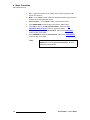
qê~åëáíáçå=pÉÅíáçå
The figure below illustrates the Transition Section.
WIPE
CUT
MIX
Transitions
Figure 2-6. Transition Section
Descriptions of each button are provided below:
WIPE
WIPE — press to transition from Preview to Program at a pre-defined rate — using one of
several wipe patterns. The wipe patterns, edge types and transition rates are selected
using the Effects Menu.
•
•
In Chapter 4, refer to the “Effects Menu” section on page 63 for menu details.
In Chapter 6, refer to the “Working with Transitions” section on page 135 for
operational procedures.
CUT — press to instantly cut the images from Preview to Program.
CUT
MIX — press to dissolve from Preview to Program at a pre-defined rate. Auto transition
rates are defined using the Effects Menu.
MIX
•
•
In Chapter 4, refer to the “Effects Menu” section on page 63 for menu details.
In Chapter 6, refer to the “Working with Transitions” section on page 135 for
operational procedures.
ScreenPRO-II • User’s Guide
23
2. Hardware Orientation
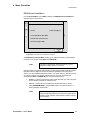
Front Panel Sections
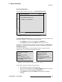
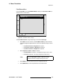
jáñÉê=cìåÅíáçåë=pÉÅíáçå
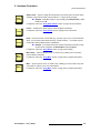
The figure below illustrates the Mixer Functions Section.
Split
Layer
Full
Screen
KEY
PIP
Clear
Layer
Swap
Z-Order
Freeze
Reset
Move
Setup
Move
Mixer Functions
Figure 2-7. Mixer Functions Sections
The buttons in the Mixer Functions Section enable you to change or modify the selected
(blinking) layer button in the Layer Control Section.
Split
Layer
Split Layer — press to select whether or not the mixer’s two layers work independently or
in tandem.
•
With Split Layer enabled (and the button lit), each layer works independently.
You have the freedom to size, position, manipulate and transition each one
independently of the other.
•
With Split Layer disabled, the two layers are ganged together, offering a variety of
additional transitions including the toggle, mix source and swap functions.
In Chapter 6, refer to the “Working with Layers” section on page 120 for details.
KEY
Full
Screen
Key — press to change the selected layer (in the Layer Control Section) and its
associated source to a key effect. The Key Adjustment Menu appears on the Touch
Screen. In Chapter 4, refer to the “Key Menu” section on page 75 for details.
Full Screen — press to take the active PIP or key to full screen. In each case, the source’s
height will be used as the parameter that defines the full screen size.
S Example: If a source’s original dimension is 1280 x 1024, pressing Full
Screen expands (or reduces) that PIP to fill the output screen vertically. If
borders are ON, they will be taken into account so that they are visible.
In Chapter 6, refer to the “Using Full Screen” section on page 129 for instructions.
PIP
Clear
Layer
24
PIP — press to change the selected layer (in the Layer Control Section) and its
associated source to a PIP effect. The PIP Adjustment Menu appears on the Touch
Screen. In Chapter 4, refer to the “PIP Adjustment Menu” section on page 67 for details.
Clear Layer — press Clear Layer to remove the currently selected (blinking) layer from
Preview — in preparation for transitioning it off Program.
In Chapter 6, refer to the “Clearing Layers from Program” section on page 128 for
instructions.
ScreenPRO-II • User’s Guide
2. Hardware Orientation
Front Panel Sections
Swap
Z-Order
Swap Z-order — press to change the visual priority (on Preview) of the two mixer layers.
The PIPs or keys remain at their current locations — only the priority changes.
S Example: If PIP B is visually on top of PIP A, press Swap Z-Order to place
PIP A on top of B.
In Chapter 6, refer to the “Using Swap Z-Order” section on page 129 for instructions.
Freeze — enables you to freeze a layer on both Program and Preview.
Freeze
Reset
In Chapter 6, refer to the “Using Freeze” section on page 130 for instructions.
Reset — press to reset the current effect (e.g., PIP, Key, crop, etc.) to a nominal default
value. You can think of this function as being “context sensitive” — as it resets only the
current effect, without affecting other modifications.
S Example: If you adjust a PIP’s size, border and shadow, and wish to reset
only the border, navigate to the Border Menu and press Reset.
In Chapter 6, refer to the “Using Reset” section on page 130 for details.
Move
Setup
Move Setup — press to set up a “move” for a PIP or key, enabling you to choose the
move’s start and end points.
In Chapter 6, refer to the “Using Move” section on page 132 for complete instructions.
Move — press to pend a “move” for a PIP or key, enabling you to fly the PIP or key from
one location to another on the next auto transition.
Move
In Chapter 6, refer to the “Using Move” section on page 132 for complete instructions.
ScreenPRO-II • User’s Guide
25
2. Hardware Orientation
Front Panel Sections
26
ScreenPRO-II • User’s Guide
PK==e~êÇï~êÉ=fåëí~ää~íáçå
få=qÜáë=`Ü~éíÉê
This chapter provides comprehensive installation instructions for the ScreenPRO-II
system’s hardware. The following topics are discussed:
•
•
•
•
•
•
•
Safety Precautions
Unpacking and Inspection
Site Preparation
Rack-Mount Installation
Cable and Adapter Information
Input Connection Chart
Installation
ScreenPRO-II • User’s Guide
27
3. Hardware Installation
Safety Precautions
p~ÑÉíó=mêÉÅ~ìíáçåë=
For all ScreenPRO-II installation procedures, please observe the following important safety
and handling rules to avoid damage to yourself and the equipment:
•
To protect users from electric shock, ensure that the chassis connects to earth via
the ground wire provided in the AC power Cord.
•
The AC Socket-outlet should be installed near the equipment and be easily
accessible.
råé~ÅâáåÖ=~åÇ=fåëéÉÅíáçå=
Before opening the ScreenPRO-II shipping box, inspect it for damage. If you find any
damage, notify the shipping carrier immediately for all claims adjustments. As you open
the box, compare its contents against the packing slip. If you find any shortages, contact
your sales representative.
Once you have removed all the components from their packaging and checked that all the
listed components are present, visually inspect the system to ensure there was no damage
during shipping. If there is damage, notify the shipping carrier immediately for all claims
adjustments.
páíÉ=mêÉé~ê~íáçå=
The environment in which you install your ScreenPRO-II should be clean, properly lit, free
from static, and have adequate power, ventilation, and space for all components.
o~ÅâJjçìåí=fåëí~ää~íáçå
The ScreenPRO-II chassis is designed to be rack mounted and is supplied with front rackmount hardware. Rear rack-mount brackets are available as a kit and are recommended
for use when units are mounted in transit cases.
Note
The ScreenPRO-II chassis can also be used in a “tabletop”
configuration, without rack mounting.
When rack mounting the ScreenPRO-II chassis, remember the following important points:
28
•
•
Maximum ambient operating temperature for the unit is 40 degrees C.
•
When installing multiple units into a rack, distribute them evenly to prevent
hazardous conditions that may be created by uneven weight distribution.
Leave at least one inch of space (front and rear) to ensure that the airflow through
the fan and vent holes is not restricted.
ScreenPRO-II • User’s Guide
3. Hardware Installation
Cable and Adapter Information
•
Rack mount each ScreenPRO-II chassis from the front rack ears using four rack
screws (not supplied). Rack threads may be metric or otherwise — depending
upon the rack type.
•
Install the lower of the two mounting holes first.
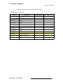
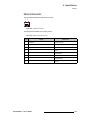
`~ÄäÉ=~åÇ=^Ç~éíÉê=fåÑçêã~íáçå
The table below provides information regarding cables and adapters:
Table 3-1. ScreenPRO-II System Cables and Adapters
Cable
Description
Note
Input Connections
HD-15 to 5xBNC Breakout Cable
Analog input connectors (via breakout)
4 Cables Supplied
HD-15 to HD-15
Analog input connections (direct)
Customer Supplied
DVI to DVI
Digital background/DSK connections (direct)
Customer Supplied
Belden 1694A (recommended)
SDI/HD-SDI input connections
Customer Supplied
Belden RG-59 (recommended)
Analog connections (via breakout)
Customer Supplied
Output Connections
HD-15 to HD-15
Analog Preview and Program outputs (direct)
Customer Supplied
DVI to DVI
Digital Program output (direct)
Customer Supplied
Remote Connections
Ethernet Hub or Switch
For use with optional Encore or ScreenPRO-II Controller
Customer Supplied
RJ-45 Ethernet Cable
For use with optional Encore or ScreenPRO-II Controller
Customer Supplied
Power Connections
AC Power Cord
ScreenPRO-II • User’s Guide
AC Power, 7 foot, 10A
1 Cord Supplied
29
3. Hardware Installation
Input Connection Chart
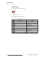
fåéìí=`çååÉÅíáçå=`Ü~êí=
The following Input Connection Chart is provided to assist with your input connections.
Please complete one chart for every ScreenPRO-II system, and make copies as required.
Please note the following important points:
•
The mixer has eight analog input connections (scaled), and with the HD model,
two scaled HD/SD inputs. Additionally, two unscaled DVI connections are
provided for background and DSK sources.
•
There is a direct correspondence between the first eight buttons in the Source
Selection Bus and the eight numbered analog input connections. No additional
button-to-source configuration is required.
•
On the HD model, there is a direct correspondence between the two SDI buttons
in the Source Selection Bus and two numbered HD/SD input connections. No
additional button-to-source configuration is required.
•
The Analog inputs can also be used to connect composite, S-Video (Y/C) and
component video. In Chapter 2, refer to the “Analog Input Flexibility” section on
page 14 for details.
•
To use two background sources, connect one to the Background A connector
and one to the Background B connector.
•
To use one background and one DSK source, connect the background to the
Background A connector and the DSK source to the Background B connector.
•
(Optional, for use with an Encore or ScreenPRO-II Controller) Two “router” modes
are available:
~
The “internal” mode is the standalone ScreenPRO-II mode, with sources
connected directly to inputs.
~
In the “external” mode, two analog outputs from a router (controlled by
the Encore or ScreenPRO-II console) are connected to ScreenPRO-II
SP analog inputs 1 and 2. In addition, two SDI outputs from a router
could be connected to SDI inputs 1 and 2.
Chart instructions:
•
•
•
•
Column 1 lists all input connectors.
Column 2 lists additional connector details:
~
Remember that the DVI connectors are digital only. There is no analog
component to them.
~
Be sure to check [ 3 ] the desired assignment of BG/DSK input B for your
later reference.
In Column 3, please list the physical source that supplies the input signal.
In Column 4, please list any notes or details pertaining to the source.
Please complete the Input Connection Chart on the following page.
30
ScreenPRO-II • User’s Guide
3. Hardware Installation
Input Connection Chart
Complete the following input connection chart for your system:
Table 3-2. Input Connection Chart
Input
Input Detail
Physical Source
Analog Input 1
Scaled
Analog Input 2
Scaled
Analog Input 3
Scaled
Analog Input 4
Scaled
Analog Input 5
Scaled
Analog Input 6
Scaled
Analog Input 7
Scaled
Analog Input 8
Scaled
HD/SD Input 1
(HD model only) Scaled
HD/SD Input 2
(HD model only) Scaled
BG Input A
Digital, Unscaled - BG [
]
BG/DSK Input B
Digital, Unscaled - BG [
] DSK [
ScreenPRO-II • User’s Guide
Note
]
31
3. Hardware Installation
Installation
fåëí~ää~íáçå
The figure below illustrates a block diagram of a basic ScreenPRO-II system. This diagram
can be used as reference in the following installation procedure.
Program
Preview
Projector
Inputs
Analog Sources to Analog Inputs 1-8
Program Out 1 (Analog)
HD/SD Sources to HD/SD Inputs 1-2
(HD Model Only)
Preview Out
DVI Sources to BG/DSK Inputs A-B
Program Out (Digital)
Ethernet
(Optional)
Genlock In
Genlock Loop (or terminate)
To Encore
Controller
Ethernet Hub / Switch
Figure 3-1. Block Diagram, Basic ScreenPRO-II System
You will need:
Table 3-3. Equipment List, Basic ScreenPRO-II System
Qty.
Item
Note
1
ScreenPRO-II Chassis
1
Video Projector
Customer supplied
1
Analog Monitor
Preview (customer supplied)
1
Analog or Digital Monitor
Program (customer supplied)
1
Ethernet Hub or Switch
Customer supplied (Optional, with Encore or ScreenPRO-II Controller)
2
Ethernet cables
Customer supplied (Optional, with Encore or ScreenPRO-II Controller)
2
Video cables
Customer supplied (Genlock and Genlock Loop)
TBD
Dedicated sources
Analog video and/or DVI as required (customer supplied)
Use the following steps to install ScreenPRO-II:
32
1.
Follow the unpacking procedures as listed in the “Unpacking and Inspection”
section on page 28.
2.
As required, refer to the “Physical and Electrical Specifications” section on
page 144 in Appendix A for electrical and mechanical details.
ScreenPRO-II • User’s Guide
3. Hardware Installation
Installation
3.
As required, refer to the “ScreenPRO-II Rear Panel” section on page 12 in
Chapter 2 for the locations of all connectors.
4.
If you are rack mounting the ScreenPRO-II chassis, follow the rack mount
procedures as outlined in the “Rack-Mount Installation” section on page 28.
5.
Ethernet Connections (optional, for use with an Encore or ScreenPRO-II
Controller) — a completely “local” network connection is recommended, without
IP connections to the outside world.
6.
7.
a.
Using an Ethernet cable, connect the ScreenPRO-II’s Ethernet port to a
Hub or Switch.
b.
Connect the Ethernet Hub or Switch to the Encore or ScreenPRO-II
Controller’s Ethernet port.
Source Connections
a.
As an important prerequisite, complete the “Input Connection Chart” on
page 30 to streamline your source installation procedure.
b.
Using the information from the chart, connect the desired sources to the
analog and digital input connectors as required.
Output Connections
a.
One Analog Preview Output is provided. Connect this output to the
input of your analog Preview Monitor.
b.
Three Program Outputs are provided: One digital and two analog. Use
these outputs to connect your Program Monitor(s) and your projector.
For example:
S Connect the Digital Program Output to the input of your projector.
S Connect Analog Program Output 1 to the input of your main
program monitor.
S Connect Analog Program Output 2 to an auxiliary or spare
program monitor.
8.
9.
Genlock Connections
a.
If you will be using synchronous video camera sources in your
production, use a BNC cable to connect a PAL or NTSC black burst or
composite sync signal to the Genlock In connector.
b.
If you are looping reference video to another chassis in your system,
connect a BNC cable from the Genlock Loop connector to the next
device’s Genlock In connector.
c.
If this ScreenPRO-II chassis is the last device in a reference video chain,
do not make any connections to the Genlock Loop connector.
d.
Once the system has powered up, complete with Genlock Termination
procedure. Refer to the “Genlock Termination” step on page 34 for
details.
Power Connection — connect an AC power cord to the AC Power Connector
on the rear of the ScreenPRO-II chassis, and then to AC outlets. Connect AC
Power cords (or AC adapters) to all peripheral equipment, such as Ethernet Hubs
and monitors. Please note:
~
~
Connect each unit only to a properly rated supply circuit.
Reliable grounding (earthing) of rack-mounted equipment should be
maintained.
10. Power On — turn on power to all units.
ScreenPRO-II • User’s Guide
33
3. Hardware Installation
Installation
11. Genlock Termination
On the rear of the ScreenPRO-II chassis, one recessed switch is provided for
genlock termination.
Note
ScreenPRO-II units are shipped from the factory with the
Termination Switch in the “terminated” (75 Ohms) position.
If the ScreenPRO-II chassis is the last device in a reference
video chain, no adjustment to the Termination Switch is
required.
a.
If you are looping reference video to another chassis in your system, wait
until the system is powered up, then access the Genlock Menu by
pressing {HOME} > {OUTPUT} > {GLCK}. This menu enables you to
see the current setting of the termination switch.
b.
Press the switch until the “high impedance” (Hi-Z) setting appears.
12. System ID — (optional, for use with an Encore or ScreenPRO-II Controller).
a.
Access the Remote Control Menu by pressing {REMOTE CONTROL}
on the Home Menu. This menu enables you to set the ID of the
ScreenPRO-II chassis.
b.
Set the ScreenPRO-II chassis ID to a value that is not used within the
Encore or ScreenPRO-II Controller’s system. The system will not
function properly if duplicate IDs are in use.
Note
Encore or ScreenPRO-II Controllers will detect multiple IDs
and prompt the user to correct the problem. Only the first
device will connect to the console. Other devices with
conflicting IDs will be refused a connection.
13. Display Calibration — calibrate the Touch Screen display using the Display
Settings Menu. From the Home Menu, press {DISPLAY} > {LCD CAL}, and
following the prompts to calibrate the display.
This completes the hardware installation procedure. Please continue with Chapter 4,
“Menu Orientation.”
34
ScreenPRO-II • User’s Guide
QK==jÉåì=lêáÉåí~íáçå
få=qÜáë=`Ü~éíÉê
This chapter describes all ScreenPRO-II system menus, including how they are accessed,
the functions that are available, and simple descriptions of each menu tree (in block
diagram format).
The following menus are discussed:
•
•
•
•
•
•
•
•
•
•
•
•
•
•
•
Home Menu
Input Menu
Output Menu
System Menu
Effects Menu
Status Menu
Display Settings Menu
PIP Adjustment Menu
Key Menu
Input Source Adjustment Menu
Background Input Setup Menu
Frame Grab Menu
DSK Adjustment Menu
LOGO Input Setup Menu
Remote Control Menu
Note
Button labels on the touch screen menus are shown in bold
upper and lowercase letters between braces.
S Press {BORDER} to …
ScreenPRO-II • User’s Guide
35
4. Menu Orientation
Home Menu
eçãÉ=jÉåì
The figure below illustrates the Home Menu:
ScreenPRO II
INPUT
OUTPUT
SYSTEM
EFFECTS
STATUS
DISPLAY
FRAME
GRAB
REMOTE
CONTROL
Figure 4-1. Home Menu
The Home Menu is the system’s top level menu, from which all other menus can be
accessed. To access a menu, press the desired button on the touch screen. You can also
return to the Home Menu by pressing the {Home} button from within an adjustment menu
itself. The {Home} button is always the top left button on a screen.
The following menus can be accessed from the Home Menu:
•
•
•
•
•
•
•
•
Press {INPUT} to access the “Input Menu.”
Press {OUTPUT} to access the “Output Menu.”
Press {SYSTEM} to access the “System Menu.”
Press {EFFECTS} to access the “Effects Menu.”
Press {STATUS} to access the “Status Menu.”
Press {DISPLAY} to access the “Display Settings Menu.”
Press {FRAME GRAB} to access the “Frame Grab Menu.”
Press {REMOTE CONTROL} to access the “Remote Control Menu.”
däçÄ~ä=oìäÉë
The following global rules apply to all menus:
36
•
Parameters and values displayed between brackets (e.g., [525] ) cannot be
changed.
•
•
Press {HOME} to return to the Home Menu.
Press {BACK} to return to the menu from which you accessed the current menu.
ScreenPRO-II • User’s Guide
4. Menu Orientation
Input Menu
fåéìí=jÉåì
The following topics are discussed in this section:
•
•
•
•
Input Menu Tree
Input Menu Description
Input Menu Functions
Input Pre and Sub Menus
fåéìí=jÉåì=qêÉÉ
The figure below illustrates the Input Menu tree:
Source Selection
HOME MENU
1
INPUT
Input
Acquisition
Menu
H
O
M
E
Input
Configuration
Menu
C
F
G
Aspect Ratio
Menu
A
R
INPUT MENU
S
A
V
E
SELECT
FORMAT
SIZING
COLOR
BALANCE
Sizing
Menu
Color
Balance
Menu
FORCE
ACQUIRE
Figure 4-2. Input Menu Tree
ScreenPRO-II • User’s Guide
37
4. Menu Orientation
Input Menu
All functions, sub menus and “pre-menus” are discussed in the following sections.
fåéìí=jÉåì=aÉëÅêáéíáçå
The figure below illustrates a sample Input Menu:
INPUT MENU
H
O
M
E
C
F
G
A
R
S
A
V
E
Format
SRC_3
1024 x 768 @ 59.94
Input Type
[ RGB ]
Color Space
[ RGB ]
Sampling Mode
[ 1:1 ]
Contrast < % >
100.0
Brightness < % >
100.0
Gamma
1.0
Input Sync Type
H/V
Pulldown Compensation
On
SELECT
FORMAT
SIZING
COLOR
BALANCE
N
A
V
A
D
J
FORCE
ACQUIRE
Figure 4-3. Input Menu (sample)
The Input Menu is used to adjust all parameters relating to inputs. Using the menu, you
can set all of the configuration options for the selected input channel.
There are several ways to access the menu:
•
•
Press {INPUT} on the Home Menu.
Select a layer button in the Layer Control Section and ensure the button is
blinking. Select an input on the Source Selection Bus and ensure the button is
blinking. If the Input Acquisition Menu appears (because the source has not yet
been saved, or because video has not been detected), press {ADJUST}.
On the Input Menu, the currently selected input is shown in the menu’s upper right corner
(e.g., SRC_3). The menu tracks the selected input, thus, if you switch inputs on the
Source Selection Bus, the menu is immediately re-assigned to the new input.
fåéìí=jÉåì=cìåÅíáçåë
The following Input Menu functions are provided:
•
38
Format — this line performs two functions:
~
Displays the resolution that is automatically determined by the FORCE
ACQUIRE function.
~
Enables you to set the resolution of the incoming source if desired. Once
the format is selected manually with the rotary knob, press {SELECT
FORMAT} to “accept” the selection.
ScreenPRO-II • User’s Guide
4. Menu Orientation
Input Menu
In Appendix A, refer to the “Input and Output Resolutions“ section on page 149
for additional details regarding resolutions.
Note
Selecting a format manually will automatically default the
Input Type. In some cases, the Input Type cannot be
changed due to the selected resolution.
•
Input Type — sets the type of input connected to the ScreenPRO-II, such as
RGB, SD, HD or Composite. Available choices change depending on the
selected format. Selections include RGB, YPbPr, Composite/S-Video, SDI
and HD SDI.
•
Color Space — sets the input’s color space. Choices include SMPTE and RGB.
Note that the system will automatically set the Color Space based on the selected
Format and Input Type.
•
Sampling Mode — sets the sampling mode for the selected input, either 1:1 or
oversample.
~
When 1:1 Sampling is selected, the system provides pixel-for-pixel
sampling, and generally better image quality.
~
When Oversample is selected, the system performs multiple samples
for every pixel, with a resulting “softer” image.
•
Contrast — sets the input’s contrast. The adjustment range is from 75% to
125%.
•
Brightness — sets the input’s brightness. The adjustment range is from 75% to
125%.
•
Gamma — sets the input gamma, enabling you to match the gamma of the
source. The adjustment range is from 1.0 to 3.0, in 0.1 increments.
•
Input Sync Type — sets the type of sync used by the selected source. Choices
include H/V, CSync (composite sync), SOG (sync on green) and Auto.
•
Pulldown Compensation — (On/Off) This function is applicable only for
standard video (component, s-video, composite) inputs. The default mode is off.
The feature should be turned on to process video derived from film material.
•
Sync Slice <mv> — This function selects the sync comparator threshold for
RGsB (RGB with Sync on Green) or YPbPr analog component video sources.
The value ranges from 20mV to 280mV and is adjustable in steps of 10mV. The
default value is 160mV.
When ScreenPRO-II detects Macrovision® copy protection on the incoming YPbPr
NTSC/PAL video, the Sync Slice value is repositioned to 60mV to account for the
reduced amplitude sync pulse.
Note
•
The default Sync Slice level has been optimized for virtually
all sources that will be encountered and should rarely, if ever,
require adjustment. However, the ability to adjust the Sync
Slice level is provided to improve sync detection and
synchronization in cases of extremely noisy RGsB or YPbPr
video signals.
Sharpness — sets the input’s sharpness. The adjustment range is from -10 (soft)
to 10 (sharp).
ScreenPRO-II • User’s Guide
39
4. Menu Orientation
Input Menu
•
Press {CFG} to display the Input Configuration Menu. Refer to the “Input
Configuration Menu” section on page 42 for details.
•
Press {AR} to display the Aspect Ratio Menu. Refer to the “Aspect Ratio Menu”
section on page 46 for details.
•
Press {SAVE} to save the selected input in the designated input file.
Note
Every sub menu under the Input Menu includes a {SAVE}
button. This enables you to save the input at any point in the
adjustment process, regardless of your location within the
menu tree. The “save” uses the information selected on the
Input Configuration Menu.
•
Press {SELECT FORMAT} to “accept” a manually selected input format. In
Appendix A, refer to the “Input and Output Resolutions“ section on page 149 for
details on all available resolutions.
•
Press {SIZING} to display the Sizing Menu. Refer to the “Sizing Menu” section
on page 43 for details.
•
Press {COLOR BALANCE} to display the Color Balance Menu. Refer to the
“Color Balance Menu” section on page 45 for details.
•
Press {FORCE ACQUIRE} to force the system to perform the optimum image
setup. Use this feature as a good starting point for setup, as required.
Note
The FORCE ACQUIRE command only works on the
selected input — not on all inputs simultaneously.
If you have made changes to the selected input, use the Input Configuration Menu to
save your changes. See the “Input Configuration Menu” section on page 42 for details.
fåéìí=mêÉ=~åÇ=pìÄ=jÉåìë
The following pre and sub menus can be accessed from the Input Menu:
•
•
•
•
•
40
Input Acquisition Menu
Input Configuration Menu
Sizing Menu
Color Balance Menu
Aspect Ratio Menu
ScreenPRO-II • User’s Guide
4. Menu Orientation
Input Menu
fåéìí=^Åèìáëáíáçå=jÉåì
The figure below illustrates a “pre” menu — the Input Acquisition Menu.
INPUT ACQUISITION
H
O
M
E
SRC_3
Source acquired.
Select ADJUST to adjust source
or SAVE to save configuration.
S
A
V
E
ADJUST
Figure 4-4. Input Acquisition Menu: No File Saved (sample)
The Input Acquisition Menu appears if you have selected a source, video is present and
the source is “acquired” — but the source has not been saved.
•
•
Press {SAVE} to save the source and display the Input Menu, or ...
Press {ADJUST} to display the Input Menu without saving the source.
Once the source has been saved, the next time you select the source, the Input Menu will
be displayed — or the source will simply switch (if you are on another menu, such as the
PIP Adjustment Menu).
If you select a source and there is a video mismatch, if video is not present or if the
acquisition fails, one of the following messages will appear:
File mismatch or no video
detected.
Check cable connections
for input _______ .
Ensure video source is present.
Select FORCE ACQUIRE once video
is reconnected.
Source acquisition failed.
Check cable connections
for input _______ .
Ensure video source is present.
Select FORCE ACQUIRE once video
is reconnected.
Figure 4-5. Input Acquisition Menu: Mismatch or No Video (sample)
In this situation, the following actions are recommended:
•
•
Check all cable connections for the selected input.
•
Press {ADJUST} to display the Input Menu without performing a FORCE
ACQUIRE.
With a connection established, press {FORCE ACQUIRE} to perform the optimum
image setup and automatically display the Input Menu, or ...
ScreenPRO-II • User’s Guide
41
4. Menu Orientation
Input Menu
fåéìí=`çåÑáÖìê~íáçå=jÉåì
From the Input Menu, press {CFG} to display the Input Configuration Menu, a sample of
which is shown below.
INPUT CONFIGURATION
H
O
M
E
SRC_3
File Number
[3]
File Name
[ IFILE_003 ]
N
A
V
B
A
C
K
A
D
J
SAVE
DELETE
Figure 4-6. Input Configuration Menu (sample)
Each input has an associated input file that stores all input parameters and settings. Each
time an input is selected in the Source Selection Bus, its associated file is recalled — in
the instant before it appears on Preview.
The Input Configuration Menu enables you to save the input’s associated file — which
guarantees that the exact parameters you set are those that are used on air.
The following functions are provided:
42
•
File Number — sets the file number into which data is stored. In the current
version, the file number automatically defaults to the input number and cannot be
changed.
•
File Name — sets the alphanumeric file name. In the current version, the file
name automatically defaults to the input name and cannot be changed.
•
•
Press {SAVE} to save the selected input in the designated input file.
Press {DELETE} to delete the selected input file.
ScreenPRO-II • User’s Guide
4. Menu Orientation
Input Menu
páòáåÖ=jÉåì
From the Input Menu, press {SIZING} to display one of two Sizing Menus. These menus
are context sensitive — they change depending on the Sampling Mode selected on the
Input Menu.
•
•
If 1:1 Sampling is selected, the 1:1 Sizing Menu appears.
If Oversample is selected, the Oversample Sizing Menu appears.
Each menu and function is described below.
NWN=páòáåÖ=jÉåì
The figure below illustrates a sample 1:1 Sizing Menu.
1:1 SIZING
H
O
M
E
B
A
C
K
SRC_3
Clock Phase
0
H Total
[ 858 ]
H Active
720
H Position
123
V Total
[0]
V Active
486
V Position
N
A
V
A
D
J
36
S
A
V
E
FORCE
ACQUIRE
Figure 4-7. 1:1 Sizing Menu (sample)
•
Clock Phase — sets the system’s A/D converter, allowing you to select where
pixels are sampled (ideally, on the pixel’s peak). The adjustment range is -16 to
15. For optimum visual results when adjusting high-resolution computer sources,
project a burst test pattern and adjust the sampling for the minimum noise. Refer
to the “Test Pattern Menu” section on page 51 for information.
•
H Total — sets the total pixel count per line.
Note
•
•
•
•
•
This field is not adjustable for digital sources, including digital
signals on both the DVI and BNC input connectors. This field
is also not adjustable for NTSC and PAL sources, regardless
of connection type.
H Active — sets the width of the active area.
H Position — sets the start of the active area’s horizontal offset from H sync.
V Total — fixed value which cannot be adjusted.
V Active — sets the number of vertical lines in the image.
V Position — sets the start of the active area’s vertical offset from V sync.
ScreenPRO-II • User’s Guide
43
4. Menu Orientation
Input Menu
•
•
Press {SAVE} to save the selected input in the designated input file.
Press {FORCE ACQUIRE} to force the system to perform the optimum image
setup. Adjustments can be made on the 1:1 Sizing Menu.
Note
If you switch to another input, the menu does not change. If
there is no valid input video, the settings are not applicable.
lîÉêë~ãéäÉ=páòáåÖ=jÉåì
The figure below illustrates a sample Oversample Sizing Menu.
OVERSAMPLE SIZING
H
O
M
E
B
A
C
K
Right Edge
SRC_3
4062
Left Edge
606
Top Edge
36
N
A
V
519
Bottom Edge
A
D
J
S
A
V
E
FORCE
ACQUIRE
Figure 4-8. Oversample Sizing Menu (sample)
With Oversample enabled, four timing parameters are provided that enable you to adjust
the image to properly fit the image’s raster box.
•
Select and adjust Right Edge, Left Edge, Top Edge or Bottom Edge as
required, to fit the image precisely in its raster box.
•
•
Press {SAVE} to save the selected input in the designated input file.
Press {FORCE ACQUIRE} to force the system to perform the optimum image
setup. Adjustments can be made on the Oversample Sizing Menu.
Note
44
If you switch to another input, the menu does not change. If
there is no valid input video, the settings are not applicable.
ScreenPRO-II • User’s Guide
4. Menu Orientation
Input Menu
`çäçê=_~ä~åÅÉ=jÉåì
From the Input Menu, press {COLOR BALANCE} to display the Color Balance Menu, a
sample of which is shown below.
COLOR BALANCE
H
O
M
E
SRC_3
Saturation < % >
100
Hue
0
N
A
V
B
A
C
K
A
D
J
S
A
V
E
RESET
ALL
Figure 4-9. Color Balance Menu (sample)
The Color Balance Menu changes depending on the selected Input Type.
•
When RGB sources are selected, the Color Balance Menu provides individual
contrast and brightness adjustments for R, G and B. Adjustment range is -25% to
+25%.
~
~
~
•
Adjust Green Contrast and Brightness as required.
Adjust Blue Contrast and Brightness as required.
When Composite, S-Video or YPbPr is selected:
~
~
Note
•
•
Adjust Red Contrast and Brightness as required.
Adjust Saturation as required. The adjustment range is 75% to 125%.
Adjust Hue as required. The range (in degrees) is -90.0 to 90.0.
When the Input Type is YPbPr, the Hue field reads 0
because Hue does not apply to this type of source.
Press {SAVE} to save the selected input in the designated input file.
Press {RESET ALL} to return all parameters to their default values.
ScreenPRO-II • User’s Guide
45
4. Menu Orientation
Input Menu
^ëéÉÅí=o~íáç=jÉåì
From the Input Menu, press {AR} to display the Aspect Ratio Menu, a sample of which is
shown below.
ASPECT RATIO
H
O
M
E
SRC_3
Mode
Custom
Ratio
1.279
N
A
V
B
A
C
K
A
D
J
S
A
V
E
Figure 4-10. Aspect Ratio Menu (sample)
The Aspect Ratio Menu enables you to change the image’s aspect ratio to pre-defined
configurations, or enter a “custom” configuration if desired.
46
•
•
Mode — select 16:9, 5:4, 4:3, 3:2, 1:1 or Custom aspect ratios.
•
Press {SAVE} to save the selected input in the designated input file.
Ratio — when Custom is selected, the Ratio line appears. Enter a custom
aspect ratio as desired. The field is hidden when pre-defined ratios are selected.
ScreenPRO-II • User’s Guide
4. Menu Orientation
Output Menu
lìíéìí=jÉåì
The following topics are discussed in this section:
•
•
•
•
Output Menu Tree
Output Menu Description
Output Menu Functions
Output Sub Menus
lìíéìí=jÉåì=qêÉÉ
The figure below illustrates the Output Menu tree:
HOME MENU
OUTPUT
H
O
M
E
Genlock Menu
G
L
C
K
OUTPUT MENU
SELECT
FORMAT
SETTINGS
TEST
PATTERN
Settings
Menu
Test
Pattern
Menu
Figure 4-11. Output Menu Tree
All functions and sub menus are discussed in the following sections.
ScreenPRO-II • User’s Guide
47
4. Menu Orientation
Output Menu
lìíéìí=jÉåì=aÉëÅêáéíáçå
The figure below illustrates a sample Output Menu:
OUTPUT MENU
H
O
M
E
Format
1024x768 @ 59.94
Color Space
[ RGB ]
N
A
V
Press SELECT FORMAT to select
A
D
J
the output resolution.
G
L
C
K
DVI EDID format can be adjusted
S
A
V
E
to match the output format in
The HOME > SYSTEM > EDID menu.
SELECT
FORMAT
SETTINGS
TEST
PATTERN
Figure 4-12. Output Menu (sample)
The Output Menu enables you to configure ScreenPRO-II’s outputs, including the ability to
display test patterns. To access the menu:
•
Press {OUTPUT} on the Home Menu.
Note that brief “help” messages are displayed to assist you with format selection and EDID
programming.
lìíéìí=jÉåì=cìåÅíáçåë
The following Output Menu functions are provided:
•
Format — sets the resolution and frame rate at which you want to drive your
projector. To minimize synchronization problems, select a frame rate that is
consistent with your input sources.
S Example: If you are using 59.94 NTSC video inputs, run the output at the
same rate in order to reduce jutter artifacts.
After selecting a format with the rotary knob, press {SELECT FORMAT} to
“accept” the selection.
In Appendix A, refer to the “Input and Output Resolutions“ section for details on
all available resolutions.
48
•
•
Color Space — displays the output color space, which is fixed at RGB.
•
•
Press {SAVE} to save all output settings in the output file.
Press {GLCK} to display the Genlock Menu. Refer to the “Genlock Menu”
section on page 50 for details.
Press {SELECT FORMAT} to “accept” a selected output format. In Appendix A,
refer to the “Input and Output Resolutions“ section for details on all available
resolutions.
ScreenPRO-II • User’s Guide
4. Menu Orientation
Output Menu
•
Press {SETTINGS} to display the Settings Menu. Refer to the “Settings Menu”
section on page 49 for details.
•
Press {TEST PATTERN} to display the Test Pattern Menu. Refer to the “Test
Pattern Menu” section on page 51 for details.
lìíéìí=pìÄ=jÉåìë
The following sub menus can be accessed from the Output Menu:
•
•
•
Settings Menu
Genlock Menu
Test Pattern Menu
pÉííáåÖë=jÉåì
From the Output Menu, press {SETTINGS} to display the Settings Menu, a sample of
which is shown below.
SETTINGS
H
O
M
E
Output Monitor
Sync Out
B
A
C
K
Program
-H-V
SOG
Off
Gamma
1.0
N
A
V
A
D
J
Figure 4-13. Settings Menu (sample)
The Settings Menu enables you to set sync parameters for the monitors and projector
connected to the system.
•
Output Monitor — selects the monitor(s) that are affected by the sync settings,
either All, Program (affects both Program connections) or Preview.
•
Sync Out — sets the desired sync value. Select +H+V, -H-V, +H-V, -H+V or
CSync.
•
•
SOG — turns the “sync on green” signal Off or On.
Gamma — sets the output gamma to match that of your projector. The default
value is 1.0.
ScreenPRO-II • User’s Guide
49
4. Menu Orientation
Output Menu
dÉåäçÅâ=jÉåì
From the Output Menu, press {GLCK} to display the Genlock Menu, a sample of which is
shown below.
GENLOCK
H
O
M
E
Source
Black Burst
Type
[ V LOCK ]
Termination
[ 75 ohm ]
N
A
V
B
A
C
K
A
D
J
To change termination between
75 Ohm and Hi-Z, press the
switch on the rear panel
next to the Genlock Loop BNC.
Figure 4-14. Genlock Menu (sample)
The Genlock Menu tells the ScreenPRO-II which type of analog genlock signal is
connected to the Genlock In BNC connector.
•
•
Source — sets the genlock source, either Black Burst, CSync or None.
Type — displays the type of genlock provided:
~
~
~
•
When Source = None, Type = [Free-Run]
When Source = Black Burst, Type = [V Lock]
When Source = CSync, Type = [V Lock]
Termination — displays the current setting of the rear-panel Termination Switch
(either 75 ohm or Hi-Z), along with a “help” message. Please note:
~
ScreenPRO-II units are shipped from the factory with the Termination
Switch in the “terminated” (75 Ohms) position. If ScreenPRO-II is the
last device in a reference chain, no adjustment to the switch is required.
~
If you are looping reference video to another chassis in your system, set
the switch to the “high impedance” (Hi-Z) setting.
Please note:
•
•
50
PAL or NTSC black burst or composite sync signals are recommended.
Genlock is highly recommended in configurations that utilize video camera
sources.
ScreenPRO-II • User’s Guide
4. Menu Orientation
Output Menu
qÉëí=m~ííÉêå=jÉåì
From the Output Menu, press {TEST PATTERN} to display the Test Pattern Menu, a
sample of which is shown below.
TEST PATTERN
H
O
M
E
Output Monitor
All
Type
Burst
Raster Box
N
A
V
On
B
A
C
K
A
D
J
Figure 4-15. Test Pattern Menu (sample)
The Test Pattern Menu enables you to display a variety of test patterns, for system and
projector alignment.
•
Output Monitor — selects the monitor(s) that are affected by the test pattern
settings, either All, Program or Preview.
•
Type — sets the test pattern. Choose between:
~
~
~
~
~
~
~
Note
•
Off
H Ramp, V Ramp
100% Color Bars, 75% Color Bars
16x16 Grid, 32x32 Grid
Burst
50% Gray, Gray Steps 1, Gray Steps 2
White, Black, Red, Green, Blue
When the test pattern is enabled, it assumes the highest
visual priority and covers all effects beneath. When disabled,
the effects once again re-appear.
Raster Box — displays a raster box defined by the exact outer edges of the
selected output resolution. For example, if the output is set to 1024 x 768, the
raster box will encapsulate that exact format. Please note:
~
The Burst test pattern is the only pattern that is smaller than the selected
output resolution. When the Raster Box is enabled, the Burst pattern
will appear within its boundaries.
~
The Raster Box can be enabled when the test pattern is Off.
ScreenPRO-II • User’s Guide
51
4. Menu Orientation
System Menu
póëíÉã=jÉåì
The following topics are discussed in this section:
•
•
•
•
System Menu Tree
System Menu Description
System Menu Functions
System Sub Menus
póëíÉã=jÉåì=qêÉÉ
The figure below illustrates the System Menu tree:
HOME MENU
SYSTEM
H
O
M
E
Reset Menu
R
E
S
E
T
SYSTEM MENU
SW
Software
Version Menu
Diagnostics
Menu
Rotary Encoder Menu
Key Detect Menu
V
E
R
D
I
A
G
SERIAL 1
EDID
Serial 1 Port
Setup
Menu
EDID DVI
Input Format
Menu
TECH
SUPPORT
Technical
Support Menu
Figure 4-16. System Menu Tree
All functions and sub menus are discussed in the following sections.
52
ScreenPRO-II • User’s Guide
4. Menu Orientation
System Menu
póëíÉã=jÉåì=aÉëÅêáéíáçå
The figure below illustrates a sample System Menu:
SYSTEM MENU
H
O
M
E
Modify Layers On Program
R
E
S
E
T
Toggle
Off
-------------------------
N
A
V
On
Mix Src / Swap
SWAP
A
D
J
SW
V
E
R
D
I
A
G
SERIAL 1
EDID
TECH
SUPPORT
SAVE
Figure 4-17. System Menu (sample)
The System Menu enables you to configure ScreenPRO-II using various functions and
sub menus, and set the operation mode for the Split Layer button. To access the menu:
•
Press {SYSTEM} on the Home Menu.
póëíÉã=jÉåì=cìåÅíáçåë
The following System Menu functions are provided:
•
Modify Layers On Program — when enabled, you can change PIPs and Keys
directly on Program, without first setting up your “look” on Preview. When
disabled, Preview must be used to set up the next look. In Chapter 6, refer to the
“Modifying Layers On Program” section on page 136 for details.
•
Toggle — enables or disables the Toggle Mode.
Important
There are two independent toggle modes — one for the
backgrounds and one for Mix Mode. The Toggle line
indicates the mode’s status, depending on which layer button
is selected.
~
When a BG button is selected, this function applies to the Background
Toggle Mode. When the mode is enabled, the two backgrounds toggle
with each transition. In Chapter 6, refer to the “Background
Transitions” section on page 121 for details.
~
When a Layer button is selected, this function applies to the Mix Mode,
which is active only when the Split Layer button is off. When toggle is
enabled, sources toggle back and forth with each transition, in both Mix
Source and Swap modes. In Chapter 6, refer to the “Understanding
Split and Mix Modes” section on page 122 for details.
ScreenPRO-II • User’s Guide
53
4. Menu Orientation
System Menu
•
Mix Src / Swap — allows you to switch between Mix Source and Swap modes:
~
With Mix Source enabled, both of the mixer’s PIPs are perfectly colocated. Layer A and Layer B are exactly the same size — in exactly the
same position — with exactly the same border and shadow.
~
With Swap enabled, both of the mixer’s PIPs can be located
independently, with different positions, sizes, borders and shadows.
Layer A and Layer B can be positioned and sized as desired — but only
one can be on screen at a time.
In Chapter 6, refer to the “Understanding Split and Mix Modes” section on
page 122 for details on Split and Mix modes.
Important
54
The Mix Src / Swap function only appears on the System
Menu when the Split Layer button is off. When the Split
Layer button is on, the line is hidden.
•
Press {RESET} to display the Reset Menu. Refer to the “Reset Menu” section on
page 58 for details.
•
Press {SW VER} to display the Software Version Menu. Refer to the “Software
Version Menu” section on page 59 for details.
•
Press {DIAG} to display the Diagnostics Setup Menu. Refer to the
“Diagnostics Setup Menu” section on page 55 for details.
•
Press {SERIAL 1} to display the Serial 1 Port Setup Menu. Refer to the “Serial 1
Port Setup Menu” section on page 60 for details.
•
Press {EDID} to display the EDID DVI Input Format Menu. Refer to the “EDID
DVI Input Format Menu” section on page 61 for details.
•
Press {TECH SUPPORT} to display the Technical Support Menu. Refer to the
“Technical Support Menu” section on page 62 for details.
•
Press {SAVE} to save all settings in the system file.
ScreenPRO-II • User’s Guide
4. Menu Orientation
System Menu
póëíÉã=pìÄ=jÉåìë
The following sub menus can be accessed from the System Menu:
•
•
•
•
•
•
Diagnostics Setup Menu
Reset Menu
Software Version Menu
Serial 1 Port Setup Menu
EDID DVI Input Format Menu
Technical Support Menu
aá~ÖåçëíáÅë=pÉíìé=jÉåì
From the System Menu, press {DIAG} to display the Diagnostics Setup Menu, a sample
of which is shown below.
DIAGNOSTICS SETUP
H
O
M
E
Reset Rotary Encoders
NVRAM Battery
Yes
[ OK ]
N
A
V
B
A
C
K
A
D
J
START
LED TEST
ROTARY
ENCODER
KEY
DETECT
Figure 4-18. Diagnostics Setup Menu (sample)
The Diagnostics Setup Menu enables you to perform a variety of diagnostic tests on the
ScreenPRO-II. The following functions are provided:
•
Reset Rotary Encoders — (Yes/No) determines whether or not you wish to reset
the rotary encoder values when you exit the Rotary Encoder Menu.
•
•
NVRAM Battery — displays the condition of the system’s NVRAM battery.
•
Press {ROTARY ENCODER} to display the Rotary Encoder Menu. Refer to the
“Rotary Encoder Menu” section on page 56 for details.
•
Press {KEY DETECT} to display the Key Detect Menu. Refer to the “Key Detect
Menu” section on page 57 for details.
Press {START LED TEST} to begin testing all LEDs. The test takes several
minutes to complete. Press {EXIT} at the conclusion of the test.
ScreenPRO-II • User’s Guide
55
4. Menu Orientation
System Menu
oçí~êó=båÅçÇÉê=jÉåì
From the Diagnostics Setup Menu, press {ROTARY ENCODER} to display the Rotary
Encoder Menu, a sample of which is shown below.
ROTARY ENCODER DIAGNOSTICS
E
X
I
T
Rotary #
RelCnt
AbsCnt
1
0
0
2
0
0
3
0
0
Figure 4-19. Rotary Encoder Menu (sample)
The Rotary Encoder Menu enables you to test the functionality of each rotary encoder,
displaying both relative and absolute counts for each.
•
56
Press {EXIT} to return to the Diagnostics Setup Menu.
ScreenPRO-II • User’s Guide
4. Menu Orientation
System Menu
hÉó=aÉíÉÅí=jÉåì
From the Diagnostics Setup Menu, press {KEY DETECT} to display the Key Detect
Menu, a sample of which is shown below.
KEY DETECTION DIAGNOSTICS
E
X
I
T
Key Label:
Key Status:
Key Scan Code:
BG B
Released
0x8B
row=3 col=1
Please select any key.
Figure 4-20. Key Detect Menu (sample)
The Key Detect Menu shows you the key that is pressed, its status (pressed or released)
its scan code and its location in the button matrix.
•
Press {EXIT} to return to the Diagnostics Setup Menu.
ScreenPRO-II • User’s Guide
57
4. Menu Orientation
System Menu
oÉëÉí=jÉåì
From the System Menu, press {RESET} to display the Reset Menu:
SYSTEM RESET
H
O
M
E
Reset Type
SOFT
N
A
V
B
A
C
K
A
D
J
RESET
Figure 4-21. Reset Menu
The Reset Menu enables you to perform various system reset functions. The following
functions are provided:
•
Reset Type — selects the specific type of reset that you wish to perform. Choose
between SOFT or FACTORY. Note that selecting SOFT will not delete any user
defined configurations, while FACTORY deletes all user configurations.
•
Press {RESET} to perform the selected reset operation. When the confirmation
screen appears:
~
Press {YES} to start the reset procedure. An “In Progress” message will
be displayed.
~
Press {NO} to cancel the procedure.
Note
58
A factory reset will erase any “frame grab” images that have
been stored in flash memory.
ScreenPRO-II • User’s Guide
4. Menu Orientation
System Menu
pçÑíï~êÉ=sÉêëáçå=jÉåì
From the System Menu, press {SW VER} to display the Software Version Menu, a
sample of which is shown below.
SOFTWARE VERSION
H
O
M
E
ScreenPRO II
1.00
N
A
V
B
A
C
K
A
D
J
Figure 4-22. Software Version Menu (sample)
The Software Version Menu enables you to display and verify the system’s software
version. The following functions are provided:
•
ScreenPRO-II — displays the system’s current software version.
ScreenPRO-II • User’s Guide
59
4. Menu Orientation
System Menu
pÉêá~ä=N=mçêí=pÉíìé=jÉåì
From the System Menu, press {SERIAL 1} to display the Serial 1 Port Setup Menu, a
sample of which is shown below.
SERIAL 1 PORT SETUP
H
O
M
E
B
A
C
K
Baud Rate
Data Bits
Parity
Stop Bits
115200
8
N
A
V
NONE
1
A
D
J
Figure 4-23. Serial 1 Port Setup Menu (sample)
The Serial 1 Port Setup Menu enables you to set the ScreenPRO-II’s RS-232
communications parameters for serial port 1.
60
•
Baud Rate — sets the desired baud rate (2400, 4800, 9600, 14400, 19200,
28800, 38400, 57600, 115200).
•
•
•
Data Bits — sets the desired number of data bits (5, 6, 7 or 8).
Parity — sets the desired parity (None, Even, or Odd).
Stop Bits — sets the desired number of stop bits (1, 1.5 or 2).
ScreenPRO-II • User’s Guide
4. Menu Orientation
System Menu
bafa=asf=fåéìí=cçêã~í=jÉåì
From the System Menu, press {EDID} to display the EDID DVI Input Format Menu, a
sample of which is shown below.
EDID DVI Input Format
H
O
M
E
B
A
C
K
Format
1280 x 1024 @ 60
Current:
[ 1280 x 1024 @ 60 ]
A
D
J
To change EDID for BGA, BGB,
and DSK, select desired format
and select Program EDID.
PROGRAM
EDID
Figure 4-24. EDID DVI Input Format Menu (sample)
The EDID DVI Input Format Menu enables you to update the system’s preferred EDID
resolution for the two DVI inputs (BG A and BG/DSK B).
Note
This menu is designed for advanced users only. Do not
program the EDID unless it is necessary.
Extended Display Identification Data (EDID) is a VESA standard data format that contains
information about a display device and its resolution capabilities, both preferred and
allowed. The ScreenPRO-II EDID file is stored in non-volatile memory. This file is read by
an external computer’s DVI graphic card when the DVI output is connected to the
ScreenPRO-II’s BG A or BG/DSK B input connectors during boot-up.
•
Format — select the preferred DVI video format with which you want to program
the ScreenPRO-II’s EDID non-volatile memory
•
•
Current — displays the current EDID video format that resides in memory.
Press {PROGRAM EDID} to program EDID with the new selected format. A
warning message will be shown.
Note
ScreenPRO-II • User’s Guide
Once EDID programming is complete on ScreenPRO-II, you
will be prompted to power down the external computer, power
it back on again, and then ensure that the computer’s format
is set to match.
61
4. Menu Orientation
System Menu
qÉÅÜåáÅ~ä=pìééçêí=jÉåì
From the System Menu, press {TECH SUPPORT} to display the Technical Support
Menu:
TECHNICAL SUPPORT
H
O
M
E
ScreenPRO II
Phone:
1.00
866-374-7878
B
A
C
K
Figure 4-25. Technical Support Menu (sample)
The Technical Support Menu lists the current version of ScreenPRO-II software, and
displays the Technical Support phone number.
62
ScreenPRO-II • User’s Guide
4. Menu Orientation
Effects Menu
bÑÑÉÅíë=jÉåì
The figure below illustrates a sample Effects Menu:
EFFECTS MENU
H
O
M
E
Transition Rate
1.0
Transition Wipe
Wipe Down
Transition Edge
16
Key Frame Effect
N
A
V
[ LINEAR ]
A
D
J
Figure 4-26. Effects Menu (sample)
The Effects Menu allows you to modify and manage effects, including the ability to set
transition rates and wipe patterns. The following functions are provided:
•
Transition Rate — sets the auto-transition rate that is used when the WIPE or
MIX button is pressed. The transition value is in 0.1 second increments.
•
Transition Wipe — sets the type of wipe that is used when the WIPE button is
pressed. A variety of wipe patterns are provided.
•
Transition Edge — sets the width of wipe edge (in pixels) for the selected wipe
pattern.
•
Key Frame Effect — displays the type of motion used for Move effects. The
motion type is currently fixed as LINEAR.
Note
ScreenPRO-II • User’s Guide
ScreenPRO-II can perform wipes in conjunction with both
PIPs and Keys.
63
4. Menu Orientation
Status Menu
pí~íìë=jÉåì
The Status Menu provides basic software version information, as shown in the sample
menu below:
SYSTEM STATUS
H
O
M
E
ScreenPRO II
1.00
Figure 4-27. Status Menu (sample)
The following status information is provided:
•
64
ScreenPRO-II — displays the system’s current software version.
ScreenPRO-II • User’s Guide
4. Menu Orientation
Display Settings Menu
aáëéä~ó=pÉííáåÖë=jÉåì
The Display Settings Menu enables you to adjust the displays brightness and contrast, as
well as calibrate the display. A sample menu is shown below:
DISPLAY SETTINGS
H
O
M
E
Brightness
85
Contrast
97
B
R
I
T
E
C
O
N
T
R
A
S
T
RESET
LIGHT
ADJUST
LCD CAL
Figure 4-28. Display Settings Menu (sample)
The following display adjustments are provided:
•
•
•
•
Brightness — use the top rotary knob to adjust the display’s brightness.
•
Press {LCD CAL} to calibrate the touch screen display to your finger, or to a
stylus. Once pressed, you will be prompted to touch the center of a target three
times. At the conclusion of the procedure, the display is calibrated and the system
returns to the Home Menu.
Contrast — use the middle rotary knob to adjust the display’s contrast.
Press {RESET} to return the display’s settings to factory default values.
Press {LIGHT ADJUST} to adjust the backlight of the front panel buttons. The
Keypad Backlight Menu appears. Refer to the “Keypad Backlight Menu”
section on page 66 for details.
ScreenPRO-II • User’s Guide
65
4. Menu Orientation
Display Settings Menu
hÉóé~Ç=_~ÅâäáÖÜí=jÉåì
From the Display Settings Menu, press {LIGHT ADJUST} to display the Keypad
Backlight Menu, which enables you to adjust the backlight of all “dim” front panel buttons.
A sample menu is shown below:
KEYPAD BACKLIGHT
H
O
M
E
Keypad Backlight
100
A
D
J
B
A
C
K
Figure 4-29. Keypad Backlight Menu (sample)
The following adjustments are provided:
•
66
Keypad Backlight — use the top rotary knob to adjust the backlight of all “dim”
(un-selected) front panel buttons. This adjustment will assist overall button
visibility in dark control room or stage settings.
ScreenPRO-II • User’s Guide
4. Menu Orientation
PIP Adjustment Menu
mfm=^ÇàìëíãÉåí=jÉåì
The following topics are discussed in this section:
•
•
•
•
PIP Adjustment Menu Tree
PIP Adjustment Menu Description
PIP Adjustment Menu Functions
PIP Adjustment Sub Menus
mfm=^ÇàìëíãÉåí=jÉåì=qêÉÉ
The figure below illustrates the PIP Adjustment Menu tree:
LAYER
A
LAYER
A
Home Menu
H
O
M
E
Input Source
Adjustment Menu
S
R
C
Pip Adjustment Menu
Border Menu
Crop Menu
Shadow Menu
Pip Adjustment Menu
PIP
Border Menu
Pip Adjustment Menu
B
O
R
D
E
R
PIP
ADJUSTMENT
MENU
C
R
O
P
Border Menu
Input Source Adjustment Menu
Image Effects Menu
Crop Menu
Pip Adjustment Menu
Pip Adjustment Menu
Border Menu
Border Menu
Shadow Menu
Input Source Adjustment Menu
Figure 4-30. PIP Adjustment Menu Tree
All functions and sub menus are discussed in the following sections.
ScreenPRO-II • User’s Guide
67
4. Menu Orientation
PIP Adjustment Menu
mfm=^ÇàìëíãÉåí=jÉåì=aÉëÅêáéíáçå
The figure below illustrates a sample PIP Adjustment Menu:
PIP ADJUSTMENT
H
O
M
E
S
R
C
H Size < 37.3% >
674
V Size < 58.9% >
452
H Position
-34
V Position
70
S
I
Z
E
H
B
O
R
D
E
R
Move Rate
[ 2.0 ]
Key Frame Effect
P
O
S
[ LINEAR ]
V
C
R
O
P
P
O
S
TRACK
H SIZE
V SIZE
RATE
Figure 4-31. PIP Adjustment Menu (sample)
The PIP Adjustment Menu provides tools that enable you to adjust the “active” PIP. To
access the menu:
•
•
Select a blue “layer” button in the Layer Control Section.
Press the PIP button in the Layer Function Section.
The menu will immediately appear on the Touch Screen display.
Note
If you press PIP and a layer button is not selected, the system
displays a brief prompt: “LAYER A or LAYER B must be
selected.”
mfm=^ÇàìëíãÉåí=jÉåì=cìåÅíáçåë
The following PIP Adjustment Menu functions are provided:
68
•
H Size — adjusts the PIP’s horizontal size using the SIZE knob. The “%” value
indicates the PIP’s size as a percentage of the screen’s horizontal resolution. The
numeric value is the PIP’s width in pixels. Refer to the “PIP Functions” section
on page 69 for more details.
•
V Size — adjusts the PIP’s vertical size using the SIZE knob. The “%” value
indicates the PIP’s size as a percentage of the screen’s vertical resolution. The
numeric value is the PIP’s height in pixels. Refer to the “PIP Functions” section
on page 69 for more details.
•
H Position — indicates the PIP’s position, relative to the horizontal center of the
screen (00), as measured from the exact center of the PIP. Thus, the value -34 is
34 pixels to the left of center. Use the H Pos knob to move the image left and right
along the X-Axis.
ScreenPRO-II • User’s Guide
4. Menu Orientation
PIP Adjustment Menu
•
V Position — indicates the PIP’s position, relative to the vertical center of the
screen (00), as measured from the exact center of the PIP. Thus, the value 70 is
70 pixels above center. Use the V Pos knob to move the image up and down
along the Y-Axis.
•
Move Rate — adjusts the rate (in 0.1 second increments) for programmed PIP
movement, from keyframe to keyframe. To adjust, press the RATE radio button
and use the SIZE rotary knob.
•
Key Frame Effect — indicates the “motion type” that is used to move the PIP
from point to point.
~
~
If no move is programmed, the display reads [N/A].
If a move is programmed, the motion type is fixed as [Linear].
•
Press {SRC} to display the Input Source Adjustment Menu. Refer to the “Input
Source Adjustment Menu” section on page 81 for details.
•
Press {BORDER} to display the Border Menu. Refer to the “Border Menu”
section on page 70 for details.
•
Press {CROP} to display the Crop Menu. Refer to the “Crop Menu” section on
page 71 for details.
mfm=cìåÅíáçåë
At the bottom of the PIP Adjustment Menu, three radio buttons enable you to modify the
various PIP adjustment functions.
•
Press {TRACK} to lock H Size and V Size together. Regardless of the PIP’s
current aspect ratio, its size will adjust proportionally when the SIZE knob is used.
•
Press {H SIZE} to adjust only the horizontal size, leaving the vertical size alone.
In this way, you can stretch the PIP horizontally.
•
Press {V SIZE} to adjust only the vertical size, leaving the horizontal size as is. In
this way, you can stretch the PIP vertically.
•
Press {RATE} to adjust the move rate of the PIP, from keyframe to keyframe.
Note
To return the PIP to its default size and aspect ratio, press the
Reset button in the Mixer Functions Section. No other
parameters (such as Shadow or Border) will be affected.
mfm=^ÇàìëíãÉåí=pìÄ=jÉåìë
The following sub menus can be accessed via the PIP Adjustment Menu:
•
•
•
•
•
Border Menu
Crop Menu
Shadow Menu
Image Effects Menu
Input Source Adjustment Menu
ScreenPRO-II • User’s Guide
69
4. Menu Orientation
PIP Adjustment Menu
_çêÇÉê=jÉåì
From the PIP Adjustment Menu, the Input Source Adjustment Menu, the Shadow
Menu or the Image Effects Menu, press {BORDER} to display the Border Menu, a
sample of which is shown below.
BORDER
H
O
M
E
Mode
On
Style
5
Color:
P
I
P
S
H
A
D
O
W
Red
609
Green
600
Blue
531
Size Specified In
N
A
V
A
D
J
% of PIP
Size < % of PIP >
10.2
E
F
X
Figure 4-32. Border Menu (sample)
The Border Menu enables you to add a border to a PIP, and adjust its shape, style and
color as desired. The following functions are provided:
•
•
Mode — enables or disables the PIP’s border.
•
Color — enables you to individually adjust the border’s Red, Green and Blue
attributes as desired.
•
Size Specified In — select the method by which you want to specify the border
size, either as a percentage of the PIP size or in pixels.
•
Size — adjust’s the border size, using the method selected on the “Size
Specified In” line. Note that if “% of PIP” is selected and you switch to “Pixels,”
the system auto converts one display method to the other.
•
Press {PIP} to return to the PIP Adjustment Menu. Refer to the “PIP
Adjustment Menu Functions” section on page 68 for details.
•
Press {SHADOW} to display the Shadow Menu. Refer to the “Shadow Menu”
section on page 72 for details.
•
Press {EFX} to display the Image Effects Menu. Refer to the “Image Effects
Menu” section on page 73 for details.
Style — select one of many border styles, including single color and dual color
with various combinations of soft edge.
Note
70
To remove any border effects from the PIP, press the RESET
button in the Layer Functions Section. No other parameters
(such as Size or Crop) will be affected.
ScreenPRO-II • User’s Guide
4. Menu Orientation
PIP Adjustment Menu
`êçé=jÉåì
From the PIP Adjustment Menu, the Input Source Adjustment Menu, the Key Menu, or
the Key Adjustment Menu, press {CROP} to display the Crop Menu.
CROP ADJUSTMENT
H
O
M
E
H Size < 46.9% >
480
V Size < 46.9% >
360
Crop Type
S
R
C
N
A
V
ALL-SIDES
Aspect Ratio Mode
Ratio
4:3
1.333
B
O
R
D
E
R
A
D
J
P
I
P
3
TRACK SIZE
Figure 4-33. Crop Menu (sample)
The Crop Menu lets you crop the sides of a PIP or a Key — individually or proportionally,
without affecting the size of the source image. The following functions are provided:
•
H Size — adjusts the PIP or Key’s horizontal size. The “%” value indicates size as
a percentage of the screen’s horizontal resolution. The numeric value is the width
in pixels. If {TRACK SIZE} is checked, H and V crop proportionally.
•
V Size — adjusts the PIP or Key’s vertical size. The “%” value indicates size as a
percentage of the screen’s vertical resolution. The numeric value is the height in
pixels. If {TRACK SIZE} is checked, H and V crop proportionally.
•
Crop Type — selects the current type of crop function, either ALL-SIDES, TOPLEFT, or BOTTOM-RIGHT.
•
Aspect Ratio Mode — enables you to select one of several standard aspect
ratios: 16:9, 5:4, 4:3, 3:2 and 1:1.
•
Ratio — displays the corresponding ratio based on the selected Aspect Ratio
Mode: 1.777, 1.25, 1.333, 1.500, 1.000, respectively.
Note
If you select Ratio and make adjustments away from the
default setting, the Aspect Ratio Mode automatically
changes to Custom.
•
Enable the {TRACK SIZE} function to proportionally crop H Size and V Size.
Disable the function for individual parameter adjustments.
•
Press {SRC} to display the Input Source Adjustment Menu. Refer to the “Input
Source Adjustment Menu” section on page 81 for details.
•
Press {BORDER} to display the Border Menu. Refer to the “Border Menu”
section on page 70 for details.
ScreenPRO-II • User’s Guide
71
4. Menu Orientation
PIP Adjustment Menu
•
Press {PIP} to return to the PIP Adjustment Menu. Refer to the “PIP
Adjustment Menu Functions” section on page 68 for details.
Note
To remove any crop effects from the PIP or Key, press the
RESET button in the Layer Functions Section. No other
parameters will be affected.
pÜ~Ççï=jÉåì
From the Border Menu or the Image Effects Menu, press {SHADOW} to display the
Shadow Menu, a sample of which is shown below.
SHADOW
H
O
M
E
P
I
P
B
O
R
D
E
R
Mode
On
H Size < % >
106
V Size < % >
106
H Pos < pixel >
28
V Pos < pixel >
11
Transparency
N
A
V
A
D
J
100
E
F
X
3
TRACK SIZE
Figure 4-34. Shadow Menu (sample)
The Shadow Menu enables you place a shadow behind a PIP, and adjust its size, position
and transparency. The following functions are provided:
72
•
•
Mode — enables or disables the PIP’s shadow.
•
V Size < % > — adjusts the shadow’s vertical size as a percentage of the PIP’s
size. If {TRACK SIZE} is checked, H and V size adjust proportionally.
•
H Pos < pixel > — adjusts the shadow’s horizontal position in pixels, as an offset
from the PIP’s horizontal position.
•
V Pos < pixel > — adjusts the shadow’s vertical position in pixels, as an offset
from the PIP’s vertical position.
•
Transparency — adjusts the shadow’s transparency, from 0 (full transparency) to
1024 (opaque).
•
Enable the {TRACK SIZE} function to adjust the shadow’s H Size and V Size
proportionally.
•
Press {PIP} to return to the PIP Adjustment Menu. Refer to the “PIP
Adjustment Menu Functions” section on page 68 for details.
H Size < % > — adjusts the shadow’s horizontal size as a percentage of the PIP’s
size. If {TRACK SIZE} is checked, H and V size adjust proportionally.
ScreenPRO-II • User’s Guide
4. Menu Orientation
PIP Adjustment Menu
•
Press {BORDER} to display the Border Menu. Refer to the “Border Menu”
section on page 70 for details.
•
Press {EFX} to display the Image Effects Menu. Refer to the “Image Effects
Menu” section on page 73 for details.
Note
To remove any shadow effects from the PIP or Key, press the
RESET button in the Layer Functions Section. No other
parameters will be affected.
fã~ÖÉ=bÑÑÉÅíë=jÉåì
From the Border Menu and Matte Menu, press {EFX} to display the Image Effects Menu:
IMAGE EFFECTS
H
O
M
E
P
I
P
B
O
R
D
E
R
S
H
A
D
O
W
Monochrome Mode
Off
Red
100
Green
100
Blue
100
Invert
Off
Hue
N
A
V
A
D
J
0
- - - - - - STROBE - - - - - Mode
Off
Interval (frames)
2
RESET
RGB
Figure 4-35. Image Effects Menu (sample)
The Image Effects Menu enables you to creatively manipulate the selected PIP or Key:
•
Monochrome Mode — turns chroma on or off. When the mode is enabled, the
image is completely monochrome.
•
•
•
Red — adjusts the image’s red saturation. Adjustment range is 0 to 100.
•
Green — adjusts the image’s green saturation. Adjustment range is 0 to 100.
Blue — adjusts the image’s blue saturation. Adjustment range is 0 to 100.
Note
The Red, Green and Blue adjustments function whether or
not Monochrome Mode is enabled.
Tip
For a sepia tone effect, turn Monochrome Mode on, and set
Red to 100, Green to 65 and Blue to 10.
Invert — enables you to invert all image colors.
ScreenPRO-II • User’s Guide
73
4. Menu Orientation
PIP Adjustment Menu
•
Hue — adjusts the image’s hue, by rotating color vectors throughout the 360
degree color spectrum.
•
Mode — In the “Strobe” section, enables or disables the strobe mode which when
enabled, acts as a programmable freeze.
•
•
•
Interval (frames) — In the “Strobe” section, sets the freeze interval.
•
Press {BORDER} to display the Border Menu. Refer to the “Border Menu”
section on page 70 for details.
•
Press {SHADOW} to display the Shadow Menu. Refer to the “Shadow Menu”
section on page 72 for details.
Press {RESET RGB} to reset all image colors to their default values.
Press {PIP} to return to the PIP Adjustment Menu. Refer to the “PIP
Adjustment Menu Functions” section on page 68 for details.
Note
74
To remove any image effects from the PIP or Key, press the
RESET button in the Layer Functions Section. No other
parameters will be affected.
ScreenPRO-II • User’s Guide
4. Menu Orientation
Key Menu
hÉó=jÉåì
The following topics are discussed in this section:
•
•
•
•
Key Menu Tree
Key Menu Description
Key Menu Functions
Key Sub Menus
hÉó=jÉåì=qêÉÉ
The figure below illustrates the Key Menu tree:
LAYER
A
LAYER
A
KEY
Home Menu
H
O
M
E
Crop Menu
C
R
O
P
KEY
MENU
Pip Adjustment Menu
Border Menu
Input Source Adjustment Menu
MATTE
Matte Menu
SIZE &
POS
Key Adjustment
Menu
Key Menu
Key Menu
Image Effects Menu
Matte Menu
Key Adjustment Menu
Crop Menu
Figure 4-36. Key Menu Tree
All functions and sub menus are discussed in the following sections.
ScreenPRO-II • User’s Guide
75
4. Menu Orientation
Key Menu
hÉó=jÉåì=aÉëÅêáéíáçå
The figure below illustrates a sample Key Menu:
KEY
H
O
M
E
Key Type
[ Luma ]
Invert Mode
Off
Clip
N
A
V
0
Gain
1.00
Opacity
624
Fill Source
Self
A
D
J
C
R
O
P
MATTE
SIZE &
POS
Figure 4-37. Key Menu (sample)
The Key Menu provides tools to adjust the “active” key. To access the menu:
•
•
Select a blue “layer” button in the Layer Control Section.
Press the KEY button in the Layer Function Section.
The menu will immediately appear on the Touch Screen display.
Note
If you press KEY and a layer button is not selected, the
system displays a brief prompt: “LAYER A or LAYER B
must be selected.”
hÉó=jÉåì=cìåÅíáçåë
The following Key Menu functions are provided:
•
•
•
76
Key Type — displays the type of key, currently fixed as a “Luma” key.
Invert Mode — enables you to invert the key signal.
Clip — adjusts the threshold of the video that electronically “cuts” into the
background image. A hole will be cut into the background anywhere that
foreground luminance is greater than the clip level. The hole is then filled with the
Fill Source. Adjustment range is 0 to 1023.
•
Gain — adjusts the sensitivity of the keyer, enabling you to change the sharpness
of the keyed image. Gain only affects the key hole, as set by the clip. Adjustment
range is 0 to 1023.99.
•
Opacity — enables you to adjust the opacity of the keyed image, from fully
opaque to fully transparent. Adjustment range is 0 to 1024.
ScreenPRO-II • User’s Guide
4. Menu Orientation
Key Menu
•
Fill Source — determines the video that fills the key hole:
~
Self — fills the hole with the key source video itself, for example, the
video from a character generator.
~
Matte — fills the hole with a matte color, which can then be adjusted with
the Matte Menu. Refer to the “Matte Menu“ section on page 78 for
details.
•
Press {CROP} to display the Crop Menu. Refer to the “Crop Menu” section on
page 71 for details.
•
Press {MATTE} to display the Matte Menu. See the “Matte Menu” section on
page 78 for details.
•
Press {SIZE & POS} to display the Key Adjustment Menu. Refer to the “Key
Adjustment Menu” section on page 79 for details.
Note
To return the Key to its default clip values, press the RESET
button in the Layer Functions Section. No other parameters
will be affected.
hÉó=pìÄ=jÉåìë
The following sub menus can be accessed from the Key Adjustment Menu:
•
•
•
Crop Menu
Matte Menu
Key Adjustment Menu
ScreenPRO-II • User’s Guide
77
4. Menu Orientation
Key Menu
j~ííÉ=jÉåì
From the Key Menu or the Key Adjustment Menu, press {MATTE} to display the Matte
Menu, a sample of which is shown below.
MATTE
H
O
M
E
Red
528
Green
204
Blue
260
N
A
V
K
E
Y
A
D
J
E
F
X
SIZE &
POS
TRACK RGB
Figure 4-38. Matte Menu (sample)
The Matte Menu enables you to adjust the fill color of a matte key. The following functions
are provided:
•
•
•
•
Red — adjust the red component of the matte fill as required, from 0 to 1023.
•
Press {EFX} to display the Image Effects Menu. Refer to the “Image Effects
Menu” section on page 73 for details.
•
Enable the {TRACK RGB} function to adjust Red, Green and Blue proportionally.
Disable the function to adjust colors individually.
•
Press {SIZE & POS} to display the Key Adjustment Menu. Refer to the “Key
Adjustment Menu” section on page 79 for details.
Green — adjust the green component of the matte fill as required, from 0 to 1023.
Blue — adjust the blue component of the matte fill, from 0 to 1023.
Press {KEY} to return to the Key Menu. Refer to the “Key Menu Description”
section on page 76 for details.
Note
78
To return all matte values to 512, press the RESET button in
the Layer Functions Section. No other parameters will be
affected.
ScreenPRO-II • User’s Guide
4. Menu Orientation
Key Menu
hÉó=^ÇàìëíãÉåí=jÉåì
From the Key Menu and the Matte Menu, press {SIZE & POS} to display the Key
Adjustment Menu, a sample of which is shown below.
KEY ADJUSTMENT
H
O
M
E
K
E
Y
H Size < 33.5% >
606
V Size < 58.3% >
448
H Position
-160
V Position
64
S
I
Z
E
H
M
A
T
T
E
Move Rate
2.0
Key Frame Effect
P
O
S
[ N/A ]
V
C
R
O
P
P
O
S
TRACK
H SIZE
V SIZE
RATE
Figure 4-39. Key Adjustment Menu (sample)
The Key Adjustment Menu is virtually identical to the PIP Adjustment Menu — except
that it pertains to Keys rather than PIPs. The following functions are provided:
•
H Size — adjusts the Key’s horizontal size in pixels using the SIZE knob. The “%”
value indicates the key’s size as a percentage of the screen’s horizontal
resolution. The numeric value is the Key’s width in pixels. See the “Key
Functions” section on page 80 for more details.
•
V Size — adjusts the Key’s vertical size in pixels using the SIZE knob. The “%”
value indicates the Key’s size as a percentage of the screen’s vertical resolution.
The numeric value is the Key’s height in pixels. See the “Key Functions” section
on page 80 for more details.
•
H Position — indicates the Key’s position, relative to the horizontal center of the
screen (00), as measured from the exact center of the Key. Thus, the value -160
is 160 pixels to the left of center. Use the H Pos knob to move the key left and
right along the X-Axis.
•
V Position — indicates the Key’s position, relative to the vertical center of the
screen (00), as measured from the exact center of the Key. Thus, the value 64 is
64 pixels above center. Use the V Pos knob to move the key up and down along
the Y-Axis.
•
Move Rate — adjusts the rate (in 0.1 second increments) for programmed Key
movement, from keyframe to keyframe. To adjust, press the RATE radio button
and use the SIZE rotary knob.
•
Key Frame Effect — indicates the “motion type” that is used to move the Key
from point to point.
~
~
ScreenPRO-II • User’s Guide
If no move is programmed, the display reads [N/A].
If a move is programmed, the motion type is fixed as [Linear].
79
4. Menu Orientation
Key Menu
•
Press {KEY} to return to the Key Menu. Refer to the “Key Menu Description”
section on page 76 for details.
•
Press {MATTE} to display the Matte Menu. See the “Matte Menu” section on
page 78 for details.
•
Press {CROP} to display the Crop Menu. Refer to the “Crop Menu” section on
page 71 for details.
Note
To return the Key to its default size and aspect ratio, press the
RESET button in the Layer Functions Section. No other
parameters will be affected.
hÉó=cìåÅíáçåë
At the bottom of the Key Adjustment Menu, three radio buttons enable you to perform
various Key adjustment functions.
80
•
Press {TRACK} to lock H Size and V Size together. Regardless of the Key’s
current aspect ratio, its size will adjust proportionally when the SIZE knob is used
to change size.
•
Press {H SIZE} to adjust only the horizontal size, leaving the vertical size alone.
In this way, you can stretch the Key horizontally.
•
Press {V SIZE} to adjust only the vertical size, leaving the horizontal size as is. In
this way, you can stretch the Key vertically.
•
Press {RATE} to adjust the move rate of the Key, from keyframe to keyframe.
ScreenPRO-II • User’s Guide
4. Menu Orientation
Input Source Adjustment Menu
fåéìí=pçìêÅÉ=^ÇàìëíãÉåí=jÉåì
The following topics are discussed in this section:
•
•
•
Input Source Adjustment Menu Tree
Input Source Adjustment Menu Description
Input Source Adjustment Menu Functions
fåéìí=pçìêÅÉ=^ÇàìëíãÉåí=jÉåì=qêÉÉ
The figure below illustrates the Input Source Adjustment Menu tree:
PIP
ADJUSTMENT
MENU
CROP
ADJUSTMENT
MENU
S
R
C
S
R
C
Home Menu
H
O
M
E
Pip
Adjustment Menu
P
I
P
Input Source Adjustment Menu
Border Menu
Crop Menu
Border Menu
Pip Adjustment Menu
B
O
R
D
E
R
INPUT
SOURCE
ADJUSTMENT
MENU
C
R
O
P
Shadow Menu
Image Effects Menu
Crop Menu
Pip Adjustment Menu
Border Menu
Input Source Adjustment Menu
Figure 4-40. Input Source Adjustment Menu Tree
All functions and sub menus are discussed in the following sections.
ScreenPRO-II • User’s Guide
81
4. Menu Orientation
Input Source Adjustment Menu
fåéìí=pçìêÅÉ=^ÇàìëíãÉåí=jÉåì=aÉëÅêáéíáçå
The figure below illustrates a sample Input Source Adjustment Menu:
INPUT SOURCE ADJUSTMENT
H
O
M
E
P
I
P
H Size < 100.0% >
640
V Size < 100.0% >
475
H Position
0
V Position
0
S
I
Z
E
H
B
O
R
D
E
R
P
O
S
Move Rate
2.0
Key Frame Effect
[ N/A ]
V
C
R
O
P
P
O
S
TRACK
H SIZE
V SIZE
RATE
Figure 4-41. Input Source Adjustment Menu (sample)
The Input Source Adjustment Menu is virtually identical to the PIP and Key Adjustment
menus — except that the menu pertains to the source “inside” the PIP or Key, rather than
the boundaries of the PIP or Key itself. In this way, for example, a PIP can remain in its
exact location on screen, but you can scale or re-position the image inside the PIP.
To access the menu:
•
Press {SRC} from the PIP Adjustment Menu or the Crop Adjustment Menu.
Important
The Input Source Adjustment Menu is also used to adjust
Key sources, and the menu functions are identical. The only
difference is the menu’s title: Key Source Adjustment.
fåéìí=pçìêÅÉ=^ÇàìëíãÉåí=jÉåì=cìåÅíáçåë
The following Input Source Adjustment Menu functions are provided:
82
•
H Size — adjusts the input source’s horizontal size using the SIZE knob. The “%”
value indicates the source’s size as a percentage of the original PIP or Key’s
horizontal resolution. The numeric value is the source’s width in pixels. See the
“Input Source Functions” section on page 83 for more details.
•
V Size — adjusts the input source’s vertical size using the SIZE knob. The “%”
value indicates the size as a percentage of the original PIP or Key’s vertical
resolution. The numeric value is the source’s height in pixels. See the “Input
Source Functions” section on page 83 for more details.
•
H Position — indicates the input source’s horizontal position, relative to its default
horizontal position (00) with no offset. Thus, the value 50 is 50 pixels to the right
of its default position. Use the H Pos knob to move the source left and right along
the X-Axis.
ScreenPRO-II • User’s Guide
4. Menu Orientation
Input Source Adjustment Menu
•
V Position — indicates the input source’s vertical position, relative to its default
vertical position (00) with no offset. Thus, the value -10 is 10 pixels below its
default position. Use the V Pos knob to move the source along the Y-Axis.
•
Move Rate — adjusts the rate (in 0.1 second increments) for programmed Key or
PIP movement, from keyframe to keyframe. To adjust, press the RATE radio
button and use the SIZE rotary knob.
•
Key Frame Effect — indicates the “motion type” that is used to move the Key or
PIP from point to point.
~
~
If no move is programmed, the display reads [N/A].
If a move is programmed, the motion type is fixed as [Linear].
•
Press {PIP} to jump to the PIP Adjustment Menu. Refer to the “PIP Adjustment
Menu Functions” section on page 68 for details.
•
Press {BORDER} to display the Border Menu. Refer to the “Border Menu”
section on page 70 for details.
•
Press {CROP} to display the Crop Menu. Refer to the “Crop Menu” section on
page 71 for details.
Note
To return the input source to its default size and aspect ratio,
press the RESET button in the Layer Functions Section.
No other parameters will be affected.
fåéìí=pçìêÅÉ=cìåÅíáçåë
At the bottom of the Input Source Adjustment Menu, three radio buttons enable you to
perform various input source adjustment functions.
•
Press {TRACK} to lock H Size and V Size together. Regardless of the input
source’s current aspect ratio, its size will adjust proportionally when the SIZE
rotary knob is used.
•
Press {H SIZE} to adjust only the horizontal size, leaving the vertical size alone.
In this way, you can stretch the input source horizontally.
•
Press {V SIZE} to adjust only the vertical size, leaving the horizontal size as is. In
this way, you can stretch the input source vertically.
•
Press {RATE} to adjust the move rate of the PIP or Key, from keyframe to
keyframe.
ScreenPRO-II • User’s Guide
83
4. Menu Orientation
Background Input Setup Menu
_~ÅâÖêçìåÇ=fåéìí=pÉíìé=jÉåì
The following topics are discussed in this section:
•
•
•
Background Input Setup Menu Tree
Background Input Setup Menu Description
Background Input Setup Menu Functions
_~ÅâÖêçìåÇ=fåéìí=pÉíìé=jÉåì=qêÉÉ
The figure below illustrates the Background Input Setup Menu tree:
BG
A
Home Menu
H
O
M
E
Background
Matte Menu
M
A
T
T
E
BG
B
BACKGROUND INPUT
SETUP MENU
FRAME
GRAB
Frame Grab
Menu
Figure 4-42. Background Input Setup Menu Tree
All functions and sub menus are discussed in the following sections.
84
ScreenPRO-II • User’s Guide
4. Menu Orientation
Background Input Setup Menu
_~ÅâÖêçìåÇ=fåéìí=pÉíìé=jÉåì=aÉëÅêáéíáçå
The figure below illustrates a sample Background Input Setup Menu:
BG INPUT SETUP
H
O
M
E
R
E
S
E
T
S
A
V
E
BG_A
Type
DVI
Format
1024 x 768 @ 60
Crop: H Offset
[0]
V Offset
[0]
N
A
V
A
D
J
To change EDID for BGA, BGB and
DSK, use the HOME > SYSTEM > EDID
menu.
SELECT
FORMAT
FRAME
GRAB
FORCE
ACQUIRE
Figure 4-43. Background Input Setup Menu (sample)
The Background Input Setup Menu is used to select and define background sources A
and B. To access the menu:
•
Press either the BG A or BG B buttons in the Layer Control Section. This action
causes the selected button to blink, enabling modification.
Please note:
•
If the selected background is already on Program, the Background Input Setup
Menu will not appear.
•
If the selected background is not on Program, the menu appears.
Note
The array of buttons on the Background Input Setup Menu
changes depending upon the selected background type.
_~ÅâÖêçìåÇ=fåéìí=pÉíìé=jÉåì=cìåÅíáçåë
The following Background Input Setup Menu functions are provided:
•
Type — selects the desired background type:
~
When DVI is selected, the DVI input video is selected as supplied from a
computer or other source. In this mode, you may also choose to grab a
still frame. Ensure that the desired source is connected to the rear
panel’s BG A or BG/DSK B input.
~
When MATTE is selected, a solid color can be used as defined on the
Background Matte Menu. Refer to the “Background Matte Menu”
section on page 87 for menu details.
ScreenPRO-II • User’s Guide
85
4. Menu Orientation
Background Input Setup Menu
~
•
•
86
When FG_1, FG_2 or FG_3 is selected, a captured still frame can be
used as the background. This background type cannot be selected until
one or more frames have been captured.
Format — this line performs two functions:
~
Displays the resolution that is automatically determined by the FORCE
ACQUIRE function.
~
With DVI selected as the background type, enables you to manually set
the resolution of the incoming background source, if desired. Once the
format is selected manually with the rotary knob, press {SELECT
FORMAT} to “accept” and activate the selection.
For the two Crop settings:
~
If the background input resolution matches the output resolution, or if the
output resolution is larger than the background input resolution, the Crop
settings will be bracketed.
~
If the background input resolution is larger than the output resolution, the
H Offset and V Offset values can be used to choose which portion of the
background you want to display.
~
Press {RESET} to reset the H and V offsets to 0.
•
If Matte is selected as the Type, the {MATTE} button appears. Press {MATTE} to
display the Background Matte Menu. Refer to the “Background Matte Menu”
section on page 87 for details.
•
•
•
Press {SAVE} to store all selected background settings.
•
Press {FORCE ACQUIRE} to automatically detect the input signal resolution and
update the display Format field accordingly.
Press {SELECT FORMAT} to “activate” the selected background format.
Press {FRAME GRAB} to display the Frame Grab Menu. Refer to the “Frame
Grab Menu” section page 88 on for details.
ScreenPRO-II • User’s Guide
4. Menu Orientation
Background Input Setup Menu
_~ÅâÖêçìåÇ=j~ííÉ=jÉåì
The figure below illustrates a sample Background Matte Menu:
BG MATTE
B
A
C
K
Red
0
Green
600
Blue
900
N
A
V
M
I
N
A
D
J
M
A
X
BLACK
Figure 4-44. Background Matte Menu (sample)
The Background Matte Menu enables you to create a solid background matte color to use
behind your PIPs and Keys.
•
Red — adjust the red component of the background matte color as required, from
0 to 1023.
•
Green — adjust the green component of the background matte color as required,
from 0 to 1023.
•
Blue — adjust the blue component of the background matte color as required,
from 0 to 1023.
•
•
•
Press {MIN} to change the highlighted color to 0.
Press {MAX} to change the highlighted color to 1023.
Press {BLACK} to change all three colors to 0.
Note
ScreenPRO-II • User’s Guide
The default state is a black matte color.
87
4. Menu Orientation
Frame Grab Menu
cê~ãÉ=dê~Ä=jÉåì
The figure below illustrates a sample Frame Grab Menu:
H
O
M
E
BG FRAME GRAB
BG_A
FG to Capture
FG _1
Capture Format
[ 1280 x 1024 ]
N
A
V
Temp FG 1 Info:
[ FG1_T ]
File Name
A
D
J
[ 1280 x 1024 ]
Format
Perm FG 1 Info:
[ FG1_P ]
File Name
[ 1280 x 1024 ]
Format
CAPTURE
SAVE
DELETE
Figure 4-45. Frame Grab Menu (sample)
The Frame Grab Menu enables you to capture still frames into the system’s three internal
frame stores. The “sources” of the still frames are the system’s BG A and BG/DSK B
inputs or the scaled inputs. All captures occur on the Preview monitor — thus the desired
full screen source that you want to capture must be visible on Preview.
Once captured, a still frame can be assigned as the input “type” for BG A, BG B, the DSK
source or the LOGO source — basically any “green” button in the Layer Control Section.
Note
Resource usage applies to BG B and DSK. These two layers
are mutually exclusive — if one is on program, the other can
not be used.
The three frame stores utilize ScreenPRO-II’s “temp” (temporary) memory for on-air
production. During operation, you can overwrite the memory with new captured stills as
desired — as it takes only a few seconds to capture a still. Note that stills in “temp”
memory are lost when the system is powered down.
You can also store three stills in “permanent” flash memory, which will not be lost when the
system is powered down. At bootup, the contents of flash memory is read into “temp”
memory for use on-air. It takes several minutes to save a still into permanent memory, and
this procedure should not be performed on-air. Permanent frames can also be overwritten.
Note
88
The contents of a layer can also be captured. In Chapter 6,
refer to the “Capturing Still Frames” section on page 137 for
details.
ScreenPRO-II • User’s Guide
4. Menu Orientation
Frame Grab Menu
To access the Frame Grab Menu, use one of the following methods:
•
•
•
Press {FRAME GRAB} from either the Background A or B Input Setup Menu.
Press {FRAME GRAB} from the DSK Input Setup Menu.
Press {FRAME GRAB} from the Home Menu.
The top line of the menu will change accordingly, depending on the access path.
Note
If the selected layer is on Program, you cannot access the
Frame Grab Menu. The following prompt will be shown:
“Cannot access FRAME GRAB menu while a background,
the DSK or LOGO are on Program.”
The following Frame Grab Menu functions are provided:
•
•
•
•
FG to Capture — enables you to select FG_1, FG_2 or FG_3 for capture.
Capture Format — displays the output resolution. ScreenPRO-II always
captures a full screen image at the output resolution — regardless of the input
resolution.
In the Temp FG Info section:
~
File Name — displays the name of the file in “temp” memory.
•
The “_T” in the filename indicates that the file’s source is
temporary memory.
•
The “_P” in the filename indicates that the file is permanently
stored. If this indication appears, the permanent file has been
read into “temp” memory for use on-air.
~
Format — displays the resolution of the captured frame.
In the Perm FG Info section:
~
File Name — displays the name of the file in permanent memory.
•
The “_P” indicates that the file is permanently stored.
[EMPTY] indicates that no frame is stored.
•
~
Format — displays the resolution of the permanent frame.
•
Press {CAPTURE} to capture a still into the selected frame store. Once pressed,
the screen will indicate that the frame is being captured.
•
Press {SAVE} to save the captured frame into permanent memory (FG_1, FG_2
or FG_3). Once pressed, the screen will display a warning:
System controls will be locked
for 2 to 3 minutes while saving.
Save Now?
Figure 4-46. Background Frame Save Warning
•
~
Press YES to save the frame. All front panel controls will be locked for
up to three minutes.
~
Press NO to cancel the procedure.
Press {DELETE} to delete the selected frame from permanent storage. This
button only appears when frames are stored in permanent memory.
ScreenPRO-II • User’s Guide
89
4. Menu Orientation
DSK Adjustment Menu
aph=^ÇàìëíãÉåí=jÉåì
The following topics are discussed in this section:
•
•
•
DSK Adjustment Menu Tree
DSK Adjustment Menu Description
DSK Adjustment Menu Functions
aph=^ÇàìëíãÉåí=jÉåì=qêÉÉ
The figure below illustrates the DSK Adjustment Menu tree:
DSK
Home Menu
H
O
M
E
DSK ADJUSTMENT
MENU
INPUT
SETUP
DSK Input
Setup Menu
MATTE
DSK Matte
Adjustment
Menu
Key Adjustment Menu
Frame Grab Menu
Figure 4-47. DSK Adjustment Menu Tree
All functions and sub menus are discussed in the following sections.
90
ScreenPRO-II • User’s Guide
4. Menu Orientation
DSK Adjustment Menu
aph=^ÇàìëíãÉåí=jÉåì=aÉëÅêáéíáçå
The figure below illustrates a sample DSK Adjustment Menu:
DSK ADJUSTMENT
H
O
M
E
Key Type
[ Luma ]
Invert Mode
Off
Clip
0
Gain
1.00
Opacity
512
Fill Source
INPUT
SETUP
N
A
V
A
D
J
Matte
MATTE
Figure 4-48. DSK Adjustment Menu (sample)
The DSK Adjustment Menu enables you to adjust the selected DSK source’s key and fill
parameters. To access the menu:
•
Press the DSK button in the Layer Control Section.
aph=^ÇàìëíãÉåí=jÉåì=cìåÅíáçåë
The following DSK Adjustment Menu functions are provided:
•
•
•
Key Type — displays the type of DSK key, currently fixed as a “Luma” key.
Invert Mode — enables you to invert the DSK key signal.
Clip — adjusts the threshold of the video that “cuts” into the background. A hole
will be cut anywhere that foreground luminance is greater than the clip level. The
hole is then filled with the Fill Source. Adjustment range is 0 to 1023.
•
Gain — adjusts the keyer sensitivity, enabling you to change the key’s sharpness.
Gain only affects the key hole. Adjustment range is 0 to 1023.99.
•
Opacity — enables you to adjust the key’s opacity, from fully opaque to fully
transparent. Adjustment range is 0 to 1024.
•
Fill Source — determines the video that fills the key hole:
•
~
Self — fills the hole with the key source video itself, for example, the
video from a character generator or logo.
~
Matte — fills the hole with a matte color, which can then be adjusted with
the DSK Matte Adjustment Menu. Refer to the “DSK Matte
Adjustment Menu“ section on page 94 for details.
Press {INPUT SETUP} to display the DSK Input Setup Menu. Refer to the “DSK
Input Setup Menu” section on page 92 for details.
ScreenPRO-II • User’s Guide
91
4. Menu Orientation
DSK Adjustment Menu
•
Press {MATTE} to display the DSK Matte Adjustment Menu. This softkey only
appears when the Fill Source is set to Matte. Refer to the “DSK Matte
Adjustment Menu” section on page 94 for details.
aph=fåéìí=pÉíìé=jÉåì
From the DSK Adjustment Menu, press {INPUT SETUP} to display the DSK Input Setup
Menu, a sample of which is shown below:
DSK INPUT SETUP
H
O
M
E
DSK Input
[B]
Type
DVI
Format
K
E
Y
R
E
S
E
T
S
A
V
E
N
A
V
1024 x 768 @ 59.94
Crop: H Offset
[0]
V Offset
[0]
A
D
J
To change EDID for BGA, BGB and
DSK, use the HOME > SYSTEM > EDID
menu.
SELECT
FORMAT
FRAME
GRAB
FORCE
ACQUIRE
Figure 4-49. DSK Input Setup Menu (sample)
The DSK Input Setup Menu enables you to set the type of input used for the DSK. The
following functions are provided:
•
DSK Input — the legend [B] indicates that the Background B DVI input is
assigned to the DSK.
Important
•
•
Type — sets the type of DSK.
~
~
When None is selected, the DSK is disabled.
~
When FG_1, FG_2, or FG_3 is selected, one of the three internal frame
stores is the DSK’s input.
When DVI is selected, the DVI input video is selected as supplied from a
computer or other source. In this mode, you may also choose to grab a
still frame. Ensure that the desired source is connected to the rear
panel’s BG/DSK B input.
Format — this line performs two functions:
~
92
Remember that resource usage applies to DSK and BG B.
These two layers are mutually exclusive — if one is on
program, the other can not be used.
Displays the resolution that is automatically determined by the FORCE
ACQUIRE function.
ScreenPRO-II • User’s Guide
4. Menu Orientation
DSK Adjustment Menu
~
•
With DVI selected as the DSK type, enables you to manually set the
resolution of the incoming background source, if desired. Once the
format is selected manually with the rotary knob, press {SELECT
FORMAT} to “accept” and activate the selection.
For the two Crop settings:
~
If the DSK source’s input resolution matches the output resolution, or if
the output resolution is larger than the DSK source’s input resolution, the
Crop settings will be bracketed.
~
If the DSK source’s input resolution is larger than the output resolution,
the H Offset and V Offset values can be used to choose which portion of
the source you want to display.
~
Press {RESET} to reset the H and V offsets to 0.
•
Press {KEY} to display the Key Adjustment Menu. Refer to the “Key
Adjustment Menu” section on page 79 for details.
•
•
•
Press {SAVE} to store all selected DSK settings.
•
Press {FORCE ACQUIRE} to automatically detect the DSK input signal resolution
and update the display Format field accordingly.
Press {SELECT FORMAT} to “activate” the selected background format.
Press {FRAME GRAB} to display the DSK Frame Grab Menu. Refer to the
“Frame Grab Menu” section page 88 on for details.
ScreenPRO-II • User’s Guide
93
4. Menu Orientation
DSK Adjustment Menu
aph=j~ííÉ=^ÇàìëíãÉåí=jÉåì
From the DSK Adjustment Menu, press {MATTE} to display the DSK Matte Adjustment
Menu, a sample of which is shown below:
DSK MATTE ADJUSTMENT
B
A
C
K
Red
0
Green
600
Blue
900
N
A
V
M
I
N
A
D
J
M
A
X
3
TRACK RGB
BLACK
Figure 4-50. DSK Input Setup Menu (sample)
The DSK Matte Adjustment Menu enables you to adjust the fill color of a matte key. The
following functions are provided:
94
•
•
•
•
Red — adjust the red component of the matte fill as required, from 0 to 1023.
•
•
•
Press {MIN} to change the highlighted color to 0.
Green — adjust the green component of the matte fill as required, from 0 to 1023.
Blue — adjust the blue component of the matte fill, from 0 to 1023.
Enable the {TRACK RGB} function to adjust Red, Green and Blue proportionally.
Disable the function to adjust colors individually.
Press {MAX} to change the highlighted color to 1023.
Press {BLACK} to change all three colors to 0.
ScreenPRO-II • User’s Guide
4. Menu Orientation
LOGO Input Setup Menu
ildl=fåéìí=pÉíìé=jÉåì
The figure below illustrates a sample LOGO Input Setup Menu:
LOGO INPUT SETUP
H
O
M
E
Type
FG_3
Temp FG3 Info:
[ FG3_T ]
File Name
A
D
J
[ 1280 x 1024 ]
Resolution
S
A
V
E
Figure 4-51. LOGO Input Setup Menu (sample)
The LOGO Input Setup Menu enables you to select the full screen source for the panel’s
LOGO button. Choose between the three internal frame stores, or black. Because the
LOGO is the highest priority layer and downstream of all other effects, the “black” source
can serve as a convenient way to fade all effects to black — without changing any of the
image setups underneath the LOGO.
Note
On factory reset, “black” is the default LOGO source. If you
capture a frame and assign it as the LOGO source, that
frame will be the default upon power up.
To access the menu:
•
Press the LOGO button in the Layer Control Section.
The following LOGO Input Setup Menu functions are provided:
•
Type — enables you to select still frames FG_1, FG_2, FG_3 or Black as the
LOGO source. Frames cannot be captured from the Logo Input Setup Menu.
Refer to the “Frame Grab Menu” section on page 88 for details.
•
In the Temp FG Info section:
•
~
File Name — displays the selected still frame’s temporary storage
register.
~
Resolution — displays the resolution of the selected still frame.
Press {SAVE} to save all LOGO parameters in memory.
ScreenPRO-II • User’s Guide
95
4. Menu Orientation
Remote Control Menu
oÉãçíÉ=`çåíêçä=jÉåì
The figure below illustrates a sample Remote Control Menu:
REMOTE CONTROL
Unit ID
1
Remote Control / DHCP
ON
N
A
V
Unit IP: 192.168.0.5
- - - - - STATUS - - - - A
D
J
Connected to Encore Controller
Ctrlr IP:
192.168.0.1
Destination
[1]
Router
[ Internal ]
SAVE
Figure 4-52. Remote Control Menu (sample)
The Remote Control Menu serves two purposes:
•
When using ScreenPRO-II on a standalone basis, the Remote Control Menu is
used to set communications parameters for downloading software updates — via
Ethernet communications.
•
When ScreenPRO-II is controlled from an Encore Controller, a ScreenPRO-II
Controller or a network server (e.g., via Telnet), the Remote Control Menu is
used to set the unit ID and enable/disable remote control and DHCP.
To access the menu:
•
Press {REMOTE CONTROL} on the Home Menu.
The following functions are provided:
•
Unit ID — When ScreenPRO-II is controlled from an Encore or ScreenPRO-II
Controller, this function sets the ID of the ScreenPRO-II chassis. The ID range is
1 to 32.
Important
96
Encore or ScreenPRO-II Controllers will detect multiple IDs
and prompt the user to correct the problem. Only the first
device will connect to the console. Other devices with
conflicting IDs will be refused a connection.
ScreenPRO-II • User’s Guide
4. Menu Orientation
Remote Control Menu
•
•
Remote Control/DHCP — enables or disables remote control and DHCP.
~
~
When remote control is off, the ScreenPRO-II IP address is static.
~
If a controller is not found, but another DHCP server is found (e.g., a
network server), the IP address will be assigned and displayed by the
ScreenPRO-II unit.
~
To re-establish “local” control, remote control must be turned off from the
Remote Control Menu.
When remote control is on, the {HOME} buttons disappears, the
ScreenPRO-II front panel is disabled, and the unit’s IP address is
dynamically assigned. All control now originates from the Encore
console, the ScreenPRO-II Controller’s console — or from a network
server (e.g., via Telnet).
Unit IP — displays the IP address of ScreenPRO-II.
~
When remote control is on, this address will be assigned by one of the
following device’s DHCP server:
•
Encore Controller
•
ScreenPRO-II Controller
•
Network server
~
When remote control is off, you can change the ScreenPRO-II static IP
address. When you navigate to the field, the “ ^ “ symbol appears below
the first quad, and a {NEXT IP QUAD} button appears:
•
Use the ADJ knob to change the quad’s setting.
•
Press {NEXT IP QUAD} to advance to the next quad.
•
When you reach the last quad, the {SET IP} button appears.
Press {SET IP} to store the unit’s new Static IP address.
In the “Status” section:
•
The top line indicates the connection status with the Encore or ScreenPRO-II
Controller (e.g., Not Connected, Establishing Connection, Connected, etc.).
•
Ctrlr IP — With a connection established, displays the IP address of the Encore
or ScreenPRO-II Controller.
•
Destination — with a connection established, displays the destination assigned
to ScreenPRO-II by the Encore or ScreenPRO-II Controller.
•
Router — with a connection established, displays the utilization of routers:
~
[Internal] indicates that ScreenPRO-II’s local router is used for source
connections (the eight rear-panel analog connections plus the two rearpanel SD/HD connections).
~
[External] indicates that an external (upstream) router is used for source
connections to ScreenPRO-II. In this case, and a minimum of rear-panel
ScreenPRO-II connections are used — connected directly to one or
more router outputs.
In Appendix D, refer to the “Using Remote Control” section on page 168 for additional
details.
ScreenPRO-II • User’s Guide
97
4. Menu Orientation
Remote Control Menu
98
ScreenPRO-II • User’s Guide
RK==póëíÉã=pÉíìé
få=qÜáë=`Ü~éíÉê
This chapter provides detailed instructions for setting up the ScreenPRO-II system. It is
recommended that you follow all procedures in the order outlined below:
•
•
•
•
•
•
•
•
•
•
•
Setup Prerequisites
Return to Factory Default
Touch Screen Calibration
Output Setup
Projector Setup
Quick Input Setup Procedure
Comprehensive Input Setup
Setting up Backgrounds
Setting up the DSK
Setting up the LOGO
Saving the Setup
ScreenPRO-II • User’s Guide
99
5. System Setup
Setup Prerequisites
pÉíìé=mêÉêÉèìáëáíÉë
Please note the following important setup prerequisites:
•
Ensure that you are familiar with the operations of the Touch Screen. In
Chapter 2, refer to the “Touch Screen Menu Section” heading on page 19 for
instructions.
•
In this chapter, when a procedure tells you to “scroll to” a certain line, use the
rotary knob labelled NAV to move the highlight — or simply touch the desired line
to highlight it.
•
When a procedure tells you to “adjust” or “select” a certain parameter, use the
ADJ rotary knob.
SRC_3
1
Preview
N
A
V
HD_15
SD YUV
A
D
J
SMPTE
Figure 5-1. Menu Navigation
100
ScreenPRO-II • User’s Guide
5. System Setup
Return to Factory Default
oÉíìêå=íç=c~Åíçêó=aÉÑ~ìäí
Prior to starting your setup procedures, it is recommended that you perform a factory reset.
This procedure guarantees that any previous setups (e.g., those that may have been
programmed by other users), do not remain in system memory.
Please note the following important factory default prerequisite:
•
Ensure that you are familiar with the Reset Menu. In Chapter 4, refer to the
“Reset Menu” section on page 58 for details.
Use the following steps to return the system to factory default values:
1.
From the Home Menu, press {SYSTEM} to access the System Menu.
2.
From the System Menu, press {RESET} to display the Reset Menu.
3.
On the Reset Type line, select FACTORY.
4.
Press {RESET}. When the confirmation screen appears, press {YES} to reset the
system to factory default values.
At the conclusion of the factory reset, the system will have the following basic attributes:
•
•
•
•
•
•
All files erased from memory.
No inputs selected.
Layer A selected and blinking.
PIP mode enabled.
Output resolution set to XGA: 1024x768 @ 59.94
Output raster box On (on Preview).
Note
The factory reset “defaults” are designed so that initially, your
ScreenPRO-II system is operationally compatible with a
previous model.
Please continue with the “Touch Screen Calibration” section on page 101.
qçìÅÜ=pÅêÉÉå=`~äáÄê~íáçå
Calibrating the Touch Screen is an excellent prerequisite to all setup (and operations)
procedures.
Use the following steps to calibrate your Touch Screen display:
1.
If required, press {HOME} to display the Home Menu.
2.
Press {DISPLAY} to show the Display Settings Menu.
3.
Press {LCD CAL} to display the first Touch Screen Calibration Menu.
4.
Follow the directions on screen to complete the calibration procedure.
Please continue with the “Output Setup” section on page 102.
ScreenPRO-II • User’s Guide
101
5. System Setup
Output Setup
lìíéìí=pÉíìé
Please note the following important output setup prerequisite:
•
Ensure that you know your projector’s native resolution. Refer to your projector’s
technical manual for details.
Use the following steps to set up the ScreenPRO-II output.
Note
The ScreenPRO-II output format must match your projector’s
native resolution.
1.
From the Home Menu, press {OUTPUT} to access the Output Menu.
2.
Scroll to the Format line and select your projector’s native resolution, and a frame
rate that is consistent with your inputs.
S Example: If you are using 59.94 NTSC video inputs, run the output at the
same rate in order to be synchronous.
In Appendix A, refer to the “Input and Output Resolutions“ section on page 149
for details on all available resolutions.
Please continue with the “Projector Setup” section on page 102.
mêçàÉÅíçê=pÉíìé
Please note the following important projector setup prerequisite:
•
Ensure that you are familiar with the Output Setup Menu and all sub menus
included on that screen. In Chapter 4, refer to the “Output Menu Functions”
section on page 48 for details.
Use the following steps to set up your projector.
1.
From the Home Menu, press {OUTPUT} to access the Output Menu.
2.
Press {TEST PATTERN} to access the Test Pattern Menu.
a.
Scroll to the Output Monitor line and select the monitor(s) on which you
want the test pattern to appear.
b.
Scroll to the Type line and select the Burst test pattern.
c.
Scroll to the Raster Box line and enable the Raster Box.
d.
At the projector itself, perform the following adjustments to ensure that
the ScreenPRO-II output data is properly displayed:
Note
e.
102
•
Adjust the image for a minimum amount of noise
•
Adjust the image such that the entire Raster Box is visible.
Refer to your projector’s technical manual for information on
all projector setup and adjustment procedures.
Once the projector is properly set, disable the Raster Box and select the
100% Color Bars test pattern.
ScreenPRO-II • User’s Guide
5. System Setup
Quick Input Setup Procedure
f.
3.
4.
Press {BACK} to return to the Output Menu.
Press {SETTINGS} to display the Settings Menu.
a.
Scroll to the Output Monitor line and select the monitor(s) that you want
to be affected by the sync settings.
b.
Scroll to the Sync Out line and set the desired sync value.
c.
Scroll to the SOG line and enable or disable the “sync on green” signal
as required.
d.
Scroll to the Gamma line and set the output gamma to match that of your
projector.
e.
Press {BACK} to return to the Output Menu.
Press {GLCK} to display the Genlock Menu.
a.
Scroll to the Source line and set the genlock source, either Black Burst,
CSync or None.
b.
Press {BACK} to return to the Output Menu.
5.
Press {SAVE} to save all output settings in the output file.
6.
At the projector itself, perform additional setup procedures (e.g., color balance,
alignment, etc.) as required. When all procedures are complete, you can turn the
test pattern off using the Test Pattern Menu.
Please continue with the “Quick Input Setup Procedure” section on page 103.
nìáÅâ=fåéìí=pÉíìé=mêçÅÉÇìêÉ
This procedure enables you to quickly acquire and save inputs. Please note the following
important prerequisites:
•
Ensure that you have completed your input connection chart. In Chapter 3, refer
to the “Input Connection Chart” section on page 30 for details and instructions.
•
•
Ensure that all inputs are properly connected to the chassis.
Ensure that the system has been “factory” reset. Refer to the “Return to Factory
Default” section on page 101 for details.
Use the following steps to perform a quick input setup:
1.
On the Source Selection Bus, press an input button. The system will
automatically perform a “force acquire” on the selected input, and the Input
Acquisition Menu will be displayed.
2.
If the acquisition was successful, the image will appear full screen on Preview.
~
If you are happy with the image’s appearance, press {SAVE}. The Input
Menu will appear for that specific source.
~
If an error message appears on the Input Acquisition Menu, check all
cable connections. You can then:
•
Press {FORCE ACQUIRE} to re-attempt acquisition, or ...
•
Press {ADJUST} to display the Input Menu without performing
a FORCE ACQUIRE.
To fine tune the input using the Input Menu, refer to the
“Comprehensive Input Setup” section on page 104 for details.
ScreenPRO-II • User’s Guide
103
5. System Setup
Comprehensive Input Setup
3.
Repeat steps 1 and 2 for all remaining inputs
Please note:
•
With all inputs acquired and saved, the Input Acquisition Menu will only reappear in case of LOS (Loss of Signal), or a mismatch between the saved file and
incoming video. In Chapter 6, refer to the “A Word About LOS” section on
page 119 for details on LOS.
•
If you do not press {SAVE} for a selected input, the Input Acquisition Menu will
continue to appear each time an input is selected.
•
If you need to fine tune your inputs, or if you change inputs, the Input Menu can
be accessed at any time by pressing {HOME} > {INPUT}.
Please continue with the “Comprehensive Input Setup” section on page 104.
`çãéêÉÜÉåëáîÉ=fåéìí=pÉíìé
This procedure enables you to perform a more comprehensive input setup, if required.
Note
If your initial input acquisition was successful (as performed in
the “Quick Input Setup Procedure” section on page 103),
there is no need to perform a “comprehensive” input setup.
Typically, you may wish to adjust input “sizing” to properly fit
each input within the PIP’s boundaries — so that no black
edges are visible.
Please note the following important input setup prerequisites:
•
Ensure that you are familiar with the Input Menu and all sub menus included on
that screen. In Chapter 4, refer to the “Input Menu Functions” section on
page 38 for complete details.
•
Ensure that you have completed your input connection chart. In Chapter 3, refer
to the “Input Connection Chart” section on page 30 for details and instructions.
Use the following steps to set up inputs:
104
1.
In the Layer Control Section, press a blue “layer” button (e.g., LAYER A). The
button will blink. This step ensures that you will be able to see each source inside
a PIP.
2.
In the Mixer Functions Section, ensure that PIP is selected.
3.
On the Source Selection Bus, select the input that you want to set up. The
button will blink.
4.
From the Home Menu, press {INPUT} to access the Input Menu.
a.
On the menu’s top row, ensure that the selected input is correct (e.g.,
SRC_1 or SRC_4).
b.
If required, press {FORCE ACQUIRE} to force the system to perform the
optimum setup on the selected input. If the operation is successful, the
Format, Input Type and Color Space fields should correctly reflect the
characteristics of the incoming signal.
c.
If required, scroll to the Format line and manually set the resolution of
the incoming source. In Appendix A, refer to the “Input and Output
Resolutions“ section on page 149 for details on all available resolutions.
ScreenPRO-II • User’s Guide
5. System Setup
Comprehensive Input Setup
d.
If you manually selected a format in the previous step, press {SELECT
FORMAT} to “accept” and activate the selection.
e.
If required, scroll to the Input Type line and set the type of input
connected to the chassis. Remember that available choices change
depending on the selected Format.
f.
If required, scroll to the Color Space line and set the input’s color space.
Choices include SMPTE and RGB. Note that the system may
automatically set the Color Space based on the selected Format.
g.
If required, scroll to the Sampling Mode line and set the sampling mode
for the selected input — either 1:1 or oversample.
h.
Scroll to the Contrast line and set the input’s contrast as desired.
i.
Scroll to the Brightness line and set the input’s brightness as desired.
j.
Scroll to the Gamma line and set the input gamma as desired.
k.
Scroll to the Input Sync Type line and set the type of sync used by the
selected source. Choices include H/V, CSync (composite sync), SOG
(sync on green) and Auto.
l.
For a video source that contains film transfer material, scroll to the
Pulldown Compensation line and enable or disable 3:2 sequence
detection.
m. Scroll to the Sync Slice line and adjust the threshold if desired.
Note
5.
6.
The default Sync Slice level has been optimized for virtually
all sources that will be encountered and should rarely, if ever,
require adjustment. For additional details, in Chapter 4 refer
to the “Input Menu Functions” section on page 38.
n.
Scroll to the Sharpness line and set the input’s sharpness as desired.
The adjustment range is from -10 (soft) to 10 (sharp).
o.
Press {SAVE} to save the selected input in the designated file.
p.
Press {BACK} to return to the Input Menu.
Press {SIZING} to access the Sizing Menu. This menu is context sensitive — it
changes depending on the selected Sampling Mode.
a.
If 1:1 Sampling is selected, adjust Clock Phase, H Total, H Active,
H Position, V Total, V Active and V Position as required.
b.
If Oversample is selected, adjust Right Edge, Left Edge, Top Edge or
Bottom Edge as required, to fit the image precisely in its raster box.
c.
Press {SAVE} to save the selected input in the designated file.
d.
Press {BACK} to return to the Input Menu.
Press {COLOR BALANCE} to access the Color Balance Menu.
a.
For RGB sources, adjust Red, Green and Blue Contrast and
Brightness as required.
b.
For Composite, S-Video or YPbPr sources, adjust Saturation and Hue
as required.
c.
If required, press {RESET ALL} to return to default values.
d.
Press {SAVE} to save the selected input in the designated file.
e.
Press {BACK} to return to the Input Menu.
ScreenPRO-II • User’s Guide
105
5. System Setup
Comprehensive Input Setup
7.
8.
9.
Press {AR} to access the Aspect Ratio Menu.
a.
Scroll to the Mode line and select 16:9, 5:4, 4:3, 3:2, 1:1 or Custom
aspect ratios.
b.
If Custom is selected, scroll to the Ratio line and enter a custom aspect
ratio as desired.
c.
Press {SAVE} to save the selected input in the designated file.
d.
Press {BACK} to return to the Input Menu.
When all of your adjustments are complete, press {CFG} to display the Input
Configuration Menu.
Important
If you have not already performed incremental “saves,”
ensure that you save the input configuration before you exit
the Input Menu — otherwise all of your adjustments will be
lost. Because each input has its own file, if you do not save
the input, the next time the source is selected, the input’s
default settings will be displayed.
Note
In the current version of ScreenPRO-II, the file number and
name (into which you will save data) automatically default to
the input number and cannot be changed.
a.
Press {SAVE} to save the selected input in the designated input file. All
information is stored in non-volatile flash memory.
b.
If required, press {DELETE} to delete the file.
c.
Press {BACK} to return to the Input Menu.
To set up the next input, repeat the entire procedure from step 2.
Please continue with the “Setting up Backgrounds” section on page 107.
106
ScreenPRO-II • User’s Guide
5. System Setup
Setting up Backgrounds
pÉííáåÖ=ìé=_~ÅâÖêçìåÇë
With ScreenPRO-II, you can use a DVI input, a matte color, or a still frame as a background
source. You can also change which source you use during the course of a live production
— provided that your backgrounds have been properly set up. Please note:
•
The system has two available DVI connectors (A and B) that can be used for both
Background and DSK inputs. These inputs (along with scaled images from
layers A and B) are the sources of still frames that can be captured and used as
backgrounds.
•
The BG/DSK B input is shared between Background B and the DSK, and the
on-air usage is mutually exclusive — both cannot be on-air simultaneously.
•
Because of this shared usage, you should now decide how you wish to allocate
(and setup) your background inputs — either as two background sources, or as
one background and a DSK. Please remember:
~
To use two background sources, connect one DVI source to connector A
and one to connector B.
~
To use one background and one DSK source, connect the background to
connector A and the DSK source to connector B.
The following topics are discussed in this section:
•
•
•
•
Programming EDID
Using A Matte Color as a Background
Using a DVI Input as a Background or DSK
Using a Still Frame as a Background
mêçÖê~ããáåÖ=bafa
The EDID (Extended Display Identification Data) programming procedure is a prerequisite
for background and DSK setup. The procedure guarantees proper communications at the
preferred resolution between ScreenPRO-II’s two DVI inputs and your external equipment.
Use the following steps to program the ScreenPRO-II EDID:
1.
Ensure that the ScreenPRO-II output format matches your projector’s native
resolution. Refer to the “Output Setup” section on page 102 for instructions.
2.
Ensure that the computer(s) or external equipment that you wish to use as
background source(s) are capable of supporting the selected output resolution.
3.
From the HOME MENU, press {SYSTEM} > {EDID} to display the EDID DVI Input
Format Menu.
4.
Note the Current line, which displays the current EDID video format that resides
in ScreenPRO-II memory. If this format is already set to the desired resolution, no
EDID programming is required. You can exit this procedure, and continue with
other background setup steps as needed.
5.
If a new resolution is required, use the ADJ knob to adjust the Format to the
preferred setting at which you want to program the EDID.
6.
Press {PROGRAM EDID} to program EDID with the new selected video format. A
warning message will be shown. Press {YES} to continue.
7.
Once EDID programming is complete on ScreenPRO-II, power down the external
computer and power it back on.
ScreenPRO-II • User’s Guide
107
5. System Setup
Setting up Backgrounds
8.
On your PC’s desktop, right-click to display the Display Properties Window.
9.
Select the Settings Tab, and set the resolution to match that which you just
programmed into EDID.
10. Repeat steps 7 through 9 for each external computer.
Please continue with the “Using A Matte Color as a Background” section on page 108.
rëáåÖ=^=j~ííÉ=`çäçê=~ë=~=_~ÅâÖêçìåÇ
This procedure enables you to set up a background layer as a matte color. The procedure
can also be performed during live production, enabling you to change a background from a
DVI or still frame background to a background matte color.
Use the following steps to set up a solid matte color as a background source:
1.
Clear the background layer from Program that you wish to set up. You cannot set
up a background while it is on Program.
a.
In the Layer Control Section, check if the Red LED above the BG A or
BG B buttons is lit. If so, the background is on Program.
b.
If the desired background button is not lit, press to light it. The selected
button blinks.
c.
In the Mixer Functions Section, press Clear Layer. The background
button turns off, and the layer visually clears from Preview.
d.
Press WIPE, CUT or MIX to transition the selected layer off of Program.
Note
To ensure that the full background is visible, clear all PIPs,
Keys, the DSK and the LOGO.
2.
In the Layer Control Section, press the button for the background that you want
to set up (BG A or BG B). The button will blink and its associated BG Input
Setup Menu will appear.
3.
Scroll to the Type line and select MATTE.
4.
Press {MATTE} to display the Background Matte Menu.
5.
Adjust the Red, Green and Blue values as desired. At this point, the new
background can be used on air.
6.
Press {BACK} to return to the BG Input Setup Menu, or {HOME} to return to the
Home Menu.
7.
Repeat from step 1 if you wish to set up a solid background matte color for the
other background source.
Please continue with the “Using a DVI Input as a Background or DSK” section on
page 109.
108
ScreenPRO-II • User’s Guide
5. System Setup
Setting up Backgrounds
rëáåÖ=~=asf=fåéìí=~ë=~=_~ÅâÖêçìåÇ=çê=aph
This procedure enables you to set up a DVI source as the background layer or the DSK’s
input “type.” The DVI source originates from an external computer or other external device.
It is recommended that you perform these steps as a setup procedure. However, once the
DVI input type is set, during live production you can easily do the following:
•
•
Switch a background between a Matte color, a still frame and a DVI source.
Switch the DSK between a still frame and a DVI source.
Please remember:
•
•
All switching of background or DSK “types” must be performed on Preview.
The BG/DSK B input is shared between Background B and the DSK, and the
on-air usage is mutually exclusive — both cannot be on-air simultaneously
Use the following steps to set up a DVI input as a background or the DSK source:
1.
Ensure that the ScreenPRO-II EDID is properly programmed. Refer to the
“Programming EDID” section on page 107 for instructions.
2.
Clear the background or DSK layer from Program that you wish to set up. You
cannot set up a background or the DSK while it is on Program.
a.
In the Layer Control Section, check if the Red LED above the BG A,
BG B or DSK buttons is lit. If so, the background is on Program.
b.
If the desired layer button is not lit, press to light it. The selected button
blinks.
c.
In the Mixer Functions Section, press Clear Layer. The button turns
off, and the layer visually clears from Preview.
d.
Press WIPE, CUT or MIX to transition the selected layer off of Program.
Note
3.
To ensure that the full background will be visible, clear all
PIPs, Keys, and the LOGO.
In the Layer Control Section, press the button for the layer that you want to set
up (BG A, BG B or DSK). The button will blink:
~
If a background layer was selected, the button’s associated BG Input
Setup Menu will appear.
~
If the DSK was selected, the DSK Adjustment Menu appears. Press
{INPUT SETUP} to display the DSK Input Setup Menu.
4.
Scroll to the Type line and ensure that DVI is selected.
5.
If required, press {FORCE ACQUIRE} to force the system to perform the optimum
setup on the selected layer. If the operation is successful, Format and Type
should correctly reflect the characteristics of the incoming signal.
6.
If required, scroll to the Format line and manually set the resolution of the
incoming source. In Appendix A, refer to the “Input and Output Resolutions“
section on page 149 for details on all available resolutions.
7.
If you manually selected a format in the previous step, press {SELECT FORMAT}
to “accept” and activate the selection.
ScreenPRO-II • User’s Guide
109
5. System Setup
Setting up Backgrounds
8.
9.
For the two Crop settings:
~
If the input resolution matches the output resolution, or if the output
resolution is larger than the input resolution, the Crop settings will be
bracketed.
~
If the input resolution is larger than the output resolution, adjust the H
Offset and V Offset values to choose which portion of the input you want
to display.
~
If required, press {RESET} to reset the H and V offsets to 0.
Press {SAVE} to save the selected source in the designated file.
10. To set up the next input, repeat the procedure from step 3.
Please continue with the “Using a Still Frame as a Background” section on page 110.
rëáåÖ=~=píáää=cê~ãÉ=~ë=~=_~ÅâÖêçìåÇ
This procedure enables you to capture a still frame image, and assign it as the “type” for
Background A or B. Please note:
•
Capturing still frames into “temporary” memory can be performed either as a
setup procedure or during live production.
•
Once still frames are captured, during live production you can easily switch a
selected background between Matte, a DVI input and a Still Frame.
Important
It is highly recommended that you save still frames into
“permanent” flash memory as a setup procedure — as this is
a very time-consuming step that locks the front panel of
ScreenPRO-II.
Use the following steps to assign a captured still frame as the background “type.”
1.
Ensure that your background input(s) are properly set up as DVI sources. These
background inputs are the sources of the still frames which you will capture.
Refer to the “Using a DVI Input as a Background or DSK” section on page 109
for background input setup details.
2.
In Chapter 6, refer to the “Capturing Still Frames” section on page 137 for
instructions on capturing still frames. Up to three frames can be captured into
temporary memory: FG_1, FG_2 and FG_3.
3.
In the Layer Control Section, press the button for the background that you want
to set up (BG A or BG B). The button will blink and its associated BG Input
Setup Menu will appear.
4.
Scroll to the Type line and select the desired still frame (FG_1, FG_2 and FG_3).
Please continue with the “Setting up the DSK” section on page 111.
110
ScreenPRO-II • User’s Guide
5. System Setup
Setting up the DSK
pÉííáåÖ=ìé=íÜÉ=aph
With ScreenPRO-II, you can use a DVI input or a still frame as the DSK source. You can
also change which source you use for the DSK during the course of a live production —
provided that the DSK has been properly set up.
Note
Remember that the B DVI input is shared between
Background B and the DSK, and the on-air usage is
mutually exclusive — both cannot be on-air simultaneously.
Similarly, you cannot setup the DSK if the B DVI input is
currently in use on-air.
The following topics are discussed in this section:
•
•
Using a DVI Input as the DSK
Using a Still Frame as the DSK
rëáåÖ=~=asf=fåéìí=~ë=íÜÉ=aph
This procedure enables you to set up a DVI source as the DSK’s input “type.” It is
recommended that you perform these steps as a setup procedure. However, once the
DSK is set up, during live production you can easily switch it between a captured still frame
and a DVI source — provided that you change the DSK “type” on Preview.
Use the following steps to set up a DVI input as your DSK source:
1.
Ensure that the ScreenPRO-II EDID is properly programmed. Refer to the
“Programming EDID” section on page 107 for instructions.
2.
Ensure that the DSK and Background B sources are cleared from Program. You
cannot set up the DSK while one of the two shared resources is on Program.
3.
If you have not already set up the BG/DSK B input as a DVI source, follow the
setup procedure as outlined in the “Using a DVI Input as a Background or DSK”
section on page 109.
Please continue with the “Using a Still Frame as the DSK” section on page 112.
ScreenPRO-II • User’s Guide
111
5. System Setup
Setting up the DSK
rëáåÖ=~=píáää=cê~ãÉ=~ë=íÜÉ=aph
This procedure enables you to capture a still frame image, and assign it as the “type” for
the DSK. Please note:
•
Capturing still frames into “temporary” memory can be performed either as a
setup procedure or during live production.
•
Once still frames are captured, during live production you can easily switch the
DSK between a DVI input and a Still Frame.
Important
It is highly recommended that you save still frames into
“permanent” flash memory as a setup procedure — as this is
a very time-consuming step that locks the front panel of
ScreenPRO-II.
Use the following steps to assign a captured still frame as the DSK “type.”
1.
Ensure that BG/DSK Input B is properly set up as a DVI source. This input is the
source of the still frames which you will capture (when DSK is selected on
Preview). Refer to the “Using a DVI Input as a Background or DSK” section on
page 109 for setup details.
2.
In Chapter 6, refer to the “Capturing Still Frames” section on page 137 for
instructions on capturing still frames. Up to three frames can be captured into
temporary memory: FG_1, FG_2 and FG_3.
3.
Ensure that the DSK and Background B sources are cleared from Program. You
cannot set up the DSK while one of the two shared resources is on Program.
4.
In the Layer Control Section, press the DSK button. The button will blink and
the DSK Adjustment Menu will appear.
5.
Press {INPUT SETUP} to display the DSK Input Setup Menu.
6.
Scroll to the Type line and select the desired still frame.
Please continue with the “Setting up the LOGO” section on page 113.
112
ScreenPRO-II • User’s Guide
5. System Setup
Setting up the LOGO
pÉííáåÖ=ìé=íÜÉ=ildl
With ScreenPRO-II, you can set the LOGO source as a captured still frame, or leave it as
Black (the default value upon factory reset). You can also change which source you use
during the course of a live production.
Use the following steps to set up the LOGO source:
1.
Ensure that your background input(s) are properly set up as DVI sources. These
background inputs (along with scaled images from layers A and B) are the
sources of still frames which you can capture. Refer to the “Using a DVI Input as
a Background or DSK” section on page 109 for setup details.
2.
In Chapter 6, refer to the “Capturing Still Frames” section on page 137 for
instructions on capturing still frames. Up to three frames can be captured: FG_1,
FG_2 and FG_3.
3.
Ensure that the LOGO is cleared from Program. You cannot set up the LOGO
while it is on Program.
4.
In the Layer Control Section, press the LOGO button. The button will blink and
the LOGO Input Setup Menu will appear.
5.
On the Type line, select the desired still frame, or select Black.
Note
Because the LOGO is the highest priority layer and
downstream of all other effects, the “black” source can serve
as a convenient way to fade all effects to black.
Please continue with the “Saving the Setup” section on page 113.
p~îáåÖ=íÜÉ=pÉíìé
When all system setup procedures have been completed:
1.
From the Home Menu press {SYSTEM} to display the System Menu.
2.
Press {SAVE} to save all settings in the system file.
Once pressed, the Touch Screen menu reads “Saving System Configuration.” This step
ensures that when you cycle power, the ScreenPRO-II returns to the state in which it was
configured at the time of the “save.”
ScreenPRO-II • User’s Guide
113
5. System Setup
Saving the Setup
114
ScreenPRO-II • User’s Guide
SK==léÉê~íáçåë
få=qÜáë=`Ü~éíÉê
This chapter includes operational instructions for all ScreenPRO-II modes and functions.
The following topics are discussed:
•
•
•
•
•
•
•
•
•
Prerequisites
Operational Configuration
Lookahead Preview
Working with Layers
Working with Layer Functions
Using Move
Working with Transitions
Modifying Layers On Program
Capturing Still Frames
Note
When a sequence of menu selections is required to complete
a given procedure, the ">" symbol is used to divide each
successive menu pick.
S Example: To access the Genlock Menu, press
{HOME} > {OUTPUT} > {GLCK}.
ScreenPRO-II • User’s Guide
115
6. Operations
Prerequisites
mêÉêÉèìáëáíÉë
Prior to using the ScreenPRO-II system, please ensure the following:
•
All system inputs, backgrounds, the DSK and the LOGO are properly configured.
In Chapter 5, refer to the following sections for details:
~
~
~
~
“Setting up Backgrounds“ on page 107.
“Setting up the DSK“ on page 111.
“Setting up the LOGO“ on page 113.
•
Ensure that you are familiar with all front panel controls. In Chapter 2, refer to the
“ScreenPRO-II Front Panel“ section on page 15 for details.
•
Ensure that you are familiar with all system menus, and in particular, the
operational menus. In Chapter 4, refer to the following sections for details:
~
Refer to the “PIP Adjustment Menu“ section on page 67 for details on
all PIP adjustment menu items.
~
Refer to the “Key Menu“ section on page 75 for details on all Key
adjustment menu items.
~
Refer to the “Input Source Adjustment Menu“ section on page 81 for
details on all input source adjustment parameters.
Tip
116
“Comprehensive Input Setup“ on page 104.
As you review each function in this chapter, it is
recommended that you try out each mode and feature at the
ScreenPRO-II panel itself — using a fully configured system
consisting of a Program and Preview monitor, and all the
necessary sources and backgrounds.
ScreenPRO-II • User’s Guide
6. Operations
Operational Configuration
léÉê~íáçå~ä=`çåÑáÖìê~íáçå
The following topics are discussed in this section:
•
•
•
•
•
Monitor Layout
Touch Screen Calibration
Lookahead Preview
Understanding Raster Boxes
A Word About LOS
jçåáíçê=i~óçìí
Use the following diagram as a recommended layout for your monitors.
Preview
Program
Figure 6-1. Recommended Monitor Layout
For optimum viewing and utility, place your Preview monitor on the left, and your Program
monitor on the right.
qçìÅÜ=pÅêÉÉå=`~äáÄê~íáçå
As an excellent prerequisite to all operating procedures, it is recommended that you
calibrate the Touch Screen.
Use the following steps to calibrate your Touch Screen display:
1.
If required, press {HOME} to display the Home Menu.
2.
Press {DISPLAY} to show the Display Settings Menu.
3.
Press {LCD CAL} to display the first Touch Screen Calibration Menu.
4.
Follow directions on screen to complete the calibration procedure.
ScreenPRO-II • User’s Guide
117
6. Operations
Operational Configuration
iççâ~ÜÉ~Ç=mêÉîáÉï
ScreenPRO-II uses a “lookahead” preview system that ensures the accuracy of all your
transitions. The “look” or appearance that you create on your Preview monitor represents
the exact appearance of your Program screen — after you cut, mix or wipe the images to
program.
S Example: The illustration below represents a simple Preview-to-Program
transition. SPLIT LAYER mode is on, enabling you to have two PIPs on
screen simultaneously:
Program
Program
Background A
Background A
PIP A
PIP A
PIP B
3
1
WIPE
CUT
MIX
Preview
Preview
2
4
Background A
Background A
PIP A
PIP A
PIP B
PIP B
Figure 6-2. Program-to-Preview Transition with Lookahead
•
•
•
In frame 1, Program consists of a background and a single PIP.
•
Frame 4 represents Preview after the transition. Preview will continue to match
program until you modify the preview image, in preparation for the next transition.
In frame 2, a second PIP is selected and positioned on Preview.
After the selected transition (WIPE, CUT or MIX), the PIP transitions onto
Program. Frame 3 represents the Program screen — identical to the Preview
“look” in frame 2.
With these facts in mind, ensure that you always create the desired “next” look in Preview.
In this manner, there won’t be any operational surprises:
118
•
By using lookahead, you’ll always know visually what PIPs and keys you want to
transition TO Program.
•
Conversely, you’ll always know what PIPs and keys to you wish to clear — to
visually remove elements FROM Program.
ScreenPRO-II • User’s Guide
6. Operations
Operational Configuration
råÇÉêëí~åÇáåÖ=o~ëíÉê=_çñÉë
With ScreenPRO-II, Raster Boxes are always enabled on Preview, each PIP or Key is
surrounded by a thin border that helps you identify the PIP or Key’s original layer.
•
•
The PIP or Key with a red “corner” style raster box is Layer A.
The PIP or Key with a red “dashed” raster box is Layer B.
PIP B
PIP A
Figure 6-3. Raster Box Styles (sample)
•
The "blinking" raster box is always the one enabled for modification, and its
corresponding layer button will also blink.
•
Raster boxes that are underneath other layers (such as another PIP, the DSK or
the LOGO) are still visible on Preview.
PIP A
PIP B
Figure 6-4. Raster Box Visibility (sample)
^=tçêÇ=^Äçìí=ilp
On rare occasion, you can experience LOS (loss of signal) — typically due to a poor video,
graphics or computer connection. In these cases, ScreenPRO-II obeys a precise set of
rules for how to handle the signals:
•
Scaler LOS — If there is a LOS for a video signal inside a scaler (PIP or KEY),
the video switches to black, but the scaler remains in its current size and position.
•
Background LOS — If there is a LOS for a background DVI input, the video
switches to the background’s selected matte color.
•
DSK LOS — If there is a LOS for the DSK, the system switches the DSK Off
(specifically, selecting "none" as the type).
In each case, when the video signal recovers, the system re-enables it as before.
ScreenPRO-II • User’s Guide
119
6. Operations
Working with Layers
tçêâáåÖ=ïáíÜ=i~óÉêë
The following topics are discussed in this section:
•
•
•
•
•
•
•
•
•
•
Switching Sources
Background Transitions
Understanding Split and Mix Modes
Working with PIPs in Split Mode
Working with PIPs in Mix Mode
Modifying PIPs
Working with Keys in Split Mode
Working with Keys in Mix Mode
Modifying Keys
Clearing Layers from Program
pïáíÅÜáåÖ=pçìêÅÉë
Use the following steps to switch sources into a PIP or a Key:
1.
Press a layer button in the Layer Control Section. The button blinks to indicate
that it is available for modification. If a PIP or Key is currently assigned to the
layer, its source can now be changed.
2.
Press the desired button on the Source Selection Bus to assign that source to
the PIP or Key. The source button blinks to indicate that it is selected and active
for modification.
Please note the following important points regarding sources:
120
•
•
When the Red LED above a source button is lit, the source is on Program.
•
Multiple sources can appear on Program and Preview simultaneously, but only
one button can be blinking and active for modification on Preview.
•
If you select a layer in the Layer Control Section that is lit (but not blinking), it will
blink — and the corresponding “assigned” source on the Source Selection Bus
will blink. This method also allows you to quickly verify layer/source selections.
When a source button is lit solid, the source is on Preview — but it is not active for
manipulation. Only blinking source buttons are active for modification.
ScreenPRO-II • User’s Guide
6. Operations
Working with Layers
_~ÅâÖêçìåÇ=qê~åëáíáçåë
Use the following steps to perform a background transition:
1.
BG
A
To transition from one background to another, press and light the background
button to which you want to transition. The button blinks to indicate it is selected
and active for modification on Preview. Please note:
~
If the background is already on Program, the Background Input Setup
Menu appears, but changes cannot be made.
~
If the background is not on Program, the Background Input Setup
Menu appears and the background "type" can be changed.
Note
2.
With the background button blinking and active for modification, select the type of
background to which you want to transition. Scroll to the Type line:
~
~
~
3.
4.
If you select Background B and a pop-up window alerts you
to a resource conflict, the DSK is in use on Program. The
DSK must be cleared from Program before Background B
can be used.
Select DVI to use an unscaled full-screen graphic.
Select MATTE to use a solid color. If the color has not already been set
up, press {MATTE} to display the Background Matte Menu, and adjust
the color as required. In Chapter 4, refer to the "Background Matte
Menu" section on page 87 for details.
Select FG_1, FG_2 or FG_3 to use a captured still frame as the
background source. Refer to the "Capturing Still Frames" section on
page 137 for details.
Select the desired background toggle mode. Press {HOME} > {SYSTEM} to
display the System Menu. Scroll to the Toggle line and adjust as required:
~
Enable toggle mode to toggle between the last two selected
backgrounds on each transition.
~
Disable toggle mode to retain the last selected background on the next
transition.
Perform the desired transition (WIPE, CUT or MIX) in the normal manner.
Please note the following important points regarding background transitions:
•
If BG A is on Program and BG A is selected in Preview, there will be no change of
backgrounds on the next transition. The similar situation is true for BG B.
•
If BG A is on Program and BG B is selected in Preview, BG A will transition to BG
B on the next CUT, WIPE or MIX.
ScreenPRO-II • User’s Guide
121
6. Operations
Working with Layers
råÇÉêëí~åÇáåÖ=péäáí=~åÇ=jáñ=jçÇÉë
ScreenPRO-II provides two different modes with which you can transition PIPs and Keys:
•
•
Split Mode
Mix Mode
péäáí=jçÇÉ
Split
Layer
With the Split Layer button lit, the mixer’s two layers operate independently. You can size,
position, manipulate and transition the following combinations of effects:
•
•
•
One or two PIPs
One or two Keys
One PIP and one Key
jáñ=jçÇÉ
With the Split Layer button off, the mixer’s layers are ganged together, and two mutuallyexclusive sub-modes now determine the mixer’s function: Mix Source and Swap.
Important
The Mix Source and Swap modes are enabled on the
System Menu. From the Home Menu, press {SYSTEM} to
access the menu. Scroll to the Mix Src / Swap line, and use
the ADJ rotary knob to change modes.
The Toggle and Mix Src / Swap functions are only visible
when Split Layer is off. When Split Layer is on, the two lines
are hidden.
•
With Mix Source mode enabled, both of the mixer’s PIPs or Keys are perfectly
co-located. Layer A and Layer B are exactly the same size — in exactly the same
position — with exactly the same border and shadow. This layer mode is ideal for
transitioning images inside a static PIP. Even though two identical PIPs are used,
they visually appear as one.
Mix Src / Swap
MIX SOURCE
Figure 6-5. System Menu: Mix Source Mode Enabled
•
With Swap mode enabled, both of the mixer’s PIPs or Keys can be located
independently, with different positions, sizes, borders and shadows. Layer A and
Layer B can be positioned and sized as desired — but only one can be on
Program at a time.
Mix Src / Swap
SWAP
Figure 6-6. System Menu: Swap Mode Enabled
122
ScreenPRO-II • User’s Guide
6. Operations
Working with Layers
With both Mix Source and Swap modes, one additional “transition” function can be used
without restriction.
Toggle
On
Figure 6-7. System Menu: Toggle Mode Enabled
•
With Toggle mode enabled, sources toggle back and forth with each transition.
When a PIP or Key source is selected in Preview and a transition is performed,
the Program source “flip-flops” to Preview. Subsequent transitions simply
alternate between sources. Any new source can be selected in Preview, and as
long as Toggle is on, the last two selected sources will alternate.
•
With Toggle off, the source selected in Preview stays in Preview, once the
transition is complete. In this mode, you are required to change Preview sources
manually.
Please note the following important points regarding Mix Mode:
•
In Mix Mode, there is always a layer available In Preview for a new source to be
selected and taken to Program.
•
Four transition combinations are possible:
~
~
~
~
Mix Source with Toggle On
Mix Source with Toggle Off
Swap with Toggle On
Swap with Toggle Off
tçêâáåÖ=ïáíÜ=mfmë=áå=péäáí=jçÇÉ
In Split Mode, the mixer’s two layers operate independently.
Note
Even though this mode allows you to display two PIPs (or
Keys) on air, it is more restrictive. Once both layers are on
Program, you must transition them off Program, make
changes — and then transition them back on.
Use the following steps to work with PIPs in Split Mode.
LAYER
A
1.
In the Mixer Functions Section, ensure that the Split Layer button is On.
2.
Press the desired layer button (A or B). Please note:
3.
~
~
The layer button blinks to indicate that it is active for modification.
~
On the Preview monitor, the raster box for the selected layer blinks (even
if it is hidden under another layer).
In the Source Selection Bus, the source currently assigned to the layer
blinks.
In the Mixer Functions Section, ensure that the PIP button is lit and the PIP
Adjustment Menu is visible. If the menu is not visible, press PIP.
Note
ScreenPRO-II • User’s Guide
Even if the layer is on Program, the PIP Adjustment Menu
appears, but parameters can not be adjusted.
123
6. Operations
Working with Layers
4.
On the Source Selection Bus, press the button for the desired (new) source.
The button blinks to indicate that it is selected, and the source appears within the
PIP on Preview.
5.
Adjust the PIP’s size, position, border, shadow, source image, cropping and
"special effects" as desired. Refer to the “Modifying PIPs“ section on page 125
for details.
6.
Prior to the transition, an additional PIP or key can be set up if desired in Split
Mode:
~
To set up an additional “Split Mode” PIP in Preview, repeat the
procedure from step 2.
~
To set up a Key in Preview, refer to the “Working with Keys in Split
Mode“ section on page 126.
7.
Transition the "look" to program with a WIPE, CUT or MIX. Refer to the “Working
with Transitions“ section on page 135 for details.
8.
Repeat the procedure from step 1 for the next transition.
tçêâáåÖ=ïáíÜ=mfmë=áå=jáñ=jçÇÉ
In Mix Mode, the mixer’s layers are ganged together. Both PIPs can be perfectly colocated on screen (Mix Source mode), or both can operate independently (Swap mode),
but only one PIP can be on screen at a time.
Use the following steps to work with PIPs in Mix Mode.
1.
In the Mixer Functions Section, ensure that the Split Layer button is Off.
2.
Press the desired layer button (A or B). Please note:
~
~
The layer button blinks to indicate that it is active for modification.
~
On the Preview monitor, the raster box for the selected layer blinks (even
if it is hidden under the DSK).
3.
In the Mixer Functions Section, ensure that the PIP button is lit and the PIP
Adjustment Menu is visible. If the menu is not visible, press PIP.
4.
Press {HOME} > {SYSTEM} to display the System Menu.
~
~
~
124
In the Source Selection Bus, the source currently assigned to the layer
blinks.
To co-locate the mixer’s PIPs, select MIX SOURCE.
To locate the mixer’s PIPs independently, select SWAP.
To toggle sources, enable Toggle.
5.
On the Source Selection Bus, press the button for the desired (new) source.
The button blinks to indicate that it is selected, and the source appears within the
PIP on Preview.
6.
Adjust the PIP’s size, position, border, shadow, source image, cropping and
"special effects" as desired. Refer to the “Modifying PIPs“ section on page 125
for details.
7.
Transition the new "look" to program with a MIX, WIPE or CUT. Refer to the
“Working with Transitions“ section on page 135 for details.
8.
Repeat the procedure from step 1 for the next transition.
ScreenPRO-II • User’s Guide
6. Operations
Working with Layers
jçÇáÑóáåÖ=mfmë
Use the following steps to modify a PIP:
1.
Ensure that the PIP is selected in the Layer Control Section, and active for
modification on Preview.
2.
If the PIP Adjustment Menu is not visible, press PIP in the Mixer Functions
Section.
3.
Size and Position — Use the SIZE, H POS and V POS controls in the PIP
Adjustment Menu to size and position the PIP on Preview as desired. In
Chapter 4, refer to the "PIP Adjustment Menu Description" section on page 68
for menu details.
4.
Source Size — From the PIP Adjustment Menu, press {SRC} to display the
Input Source Adjustment Menu. Use the menu to adjust the source image’s
size and position within the PIP. In Chapter 4, refer to the "Input Source
Adjustment Menu Description" section on page 82 for menu details.
5.
Crop — From the PIP Adjustment Menu, press {CROP} to display the Crop
Adjustment Menu. Use the menu to select the type of crop, the aspect ratio, and
the image’s H and V size. In Chapter 4, refer to the "Crop Menu" section on
page 71 for menu details.
6.
Border — From the PIP Adjustment Menu, press {BORDER} to display the
Border Menu. Use the menu to select the border’s style, color and size. In
Chapter 4, refer to the "Border Menu" section on page 70 for menu details.
7.
Shadow — From the Border Menu, press {SHADOW} to display the Shadow
Menu. Use the menu to choose the shadow’s size, position and transparency. In
Chapter 4, refer to the "Shadow Menu" section on page 72 for menu details.
8.
Special Effects — From the Border Menu, press {EFX} to display the Image
Effects Menu. Use the menu to select monochrome or color mode, to modify
chroma and hue, to invert the color, and to set a strobe effect. In Chapter 4, refer
to the "Image Effects Menu" section on page 73 for menu details.
9.
Global Functions — Remember that the following global functions are always
available to you:
~
Press Reset to reset the current effect (e.g., PIP, Key, crop, etc.) to a
nominal default value.
~
Press Full Screen to bring the PIP to full screen, using the source’s
height as the defining factor.
~
Press Freeze to freeze the PIP (on both Program and Preview). Press
again to unfreeze.
10. Transition — Transition the new "look" to program with a MIX, WIPE or CUT.
Refer to the “Working with Transitions“ section on page 135 for details.
ScreenPRO-II • User’s Guide
125
6. Operations
Working with Layers
tçêâáåÖ=ïáíÜ=hÉóë=áå=péäáí=jçÇÉ
In Split Mode, the mixer’s two layers operate independently.
Note
Even though this mode allows you to display two PIPs (or
Keys) on air, it is more restrictive. Once both layers are on
Program, you must transition them off Program, make
changes — and then transition them back on.
Use the following steps to work with Keys in Split Mode.
1.
In the Mixer Functions Section, ensure that the Split Layer button is On.
2.
Press the desired layer button (A or B). Please note:
3.
~
~
The layer button blinks to indicate that it is active for modification.
~
On the Preview monitor, the raster box for the selected layer blinks (even
if it is hidden under another layer).
In the Source Selection Bus, the source currently assigned to the layer
blinks.
In the Mixer Functions Section, ensure that the KEY button is lit and the Key
Menu is visible. If the menu is not visible, press KEY.
Note
Even if the layer is on Program, the Key Menu appears, but
parameters can not be adjusted.
4.
On the Source Selection Bus, press the button for the desired (new) key source.
The button blinks to indicate that it is selected, and the source appears on
Preview.
5.
Adjust the Key’s mode, clip, gain, opacity, fill source, size, position, source image
and cropping as desired. Refer to the “Modifying Keys“ section on page 127 for
details.
6.
Prior to the transition, an additional PIP or key can be set up if desired in Split
Mode:
~
To set up an additional “Split Mode” Key in Preview, repeat the
procedure from step 2.
~
To set up a PIP in Preview, refer to the “Working with PIPs in Split
Mode“ section on page 123.
7.
Transition the "look" to program with a WIPE, CUT or MIX. Refer to the “Working
with Transitions“ section on page 135 for details.
8.
Repeat the procedure from step 1 for the next transition.
tçêâáåÖ=ïáíÜ=hÉóë=áå=jáñ=jçÇÉ
In Mix Mode, the mixer’s layers are ganged together. Both Keys can be perfectly colocated on screen (Mix Source mode), or both can operate independently (Swap mode),
but only one Key can be on screen at a time.
Use the following steps to work with Keys in Mix Mode.
126
1.
In the Mixer Functions Section, ensure that the Split Layer button is Off.
2.
Press the desired layer button (A or B). Please note:
ScreenPRO-II • User’s Guide
6. Operations
Working with Layers
~
~
The layer button blinks to indicate that it is active for modification.
~
On the Preview monitor, the raster box for the selected layer blinks (even
if it is hidden under the DSK).
In the Source Selection Bus, the source currently assigned to the layer
blinks.
3.
In the Mixer Functions Section, ensure that the KEY button is lit and the Key
Menu is visible. If the menu is not visible, press KEY.
4.
Press {HOME} > {SYSTEM} to display the System Menu.
~
~
~
To co-locate the mixer’s Keys, select MIX SOURCE.
To locate the mixer’s Keys independently, select SWAP.
To toggle sources, enable Toggle.
5.
On the Source Selection Bus, press the button for the desired (new) key source.
The button blinks to indicate that it is selected, and the source appears on
Preview.
6.
Adjust the Key’s mode, clip, gain, opacity, fill source, size, position, source image
and cropping as desired. Refer to the “Modifying Keys“ section on page 127 for
details.
7.
Transition the new "look" to program with a MIX, WIPE or CUT. Refer to the
“Working with Transitions“ section on page 135 for details.
8.
Repeat the procedure from step 1 for the next transition.
jçÇáÑóáåÖ=hÉóë
Use the following steps to modify a Key:
1.
Ensure that the Key is selected in the Layer Control Section, and active for
modification on Preview.
2.
If the Key Menu is not visible, press KEY in the Mixer Functions Section.
3.
Clip, Gain, Mode, Opacity — Use the controls in the Key Menu to adjust the
Key’s clip, gain, invert mode and opacity on Preview as desired. In Chapter 4,
refer to the "Key Menu Description" section on page 76 for menu details.
4.
Fill Source — Use the controls in the Key Menu to select a self or matte fill key.
If Matte is selected, press {MATTE} to display the Matte Menu, with which you
can choose the matte fill color. In Chapter 4, refer to the "Matte Menu" section
on page 78 for menu details.
5.
Size and Position — From the Key Menu, press {SIZE & POS} to display the
Key Adjustment Menu. Use the controls to size and position the Key on Preview
as desired. In Chapter 4, refer to the "Key Adjustment Menu" section on
page 79 for menu details.
6.
Crop — From the Key Menu, press {CROP} to display the Crop Adjustment
Menu. Use the menu to select the type of crop, the aspect ratio, and the image’s
H and V size. In Chapter 4, refer to the "Crop Menu" section on page 71 for
menu details.
7.
Source Size — From the Crop Menu, press {SRC} to display the Key Source
Adjustment Menu. Use the menu to adjust the source image’s size and position
within the PIP. In Chapter 4, refer to the "Input Source Adjustment Menu
Description" section on page 82 for menu details.
ScreenPRO-II • User’s Guide
127
6. Operations
Working with Layers
8.
Special Effects — From the Matte Menu, press {EFX} to display the Image
Effects Menu. Use the menu to select monochrome or color mode, to modify
chroma and hue, to invert the color, and to set a strobe effect. In Chapter 4, refer
to the "Image Effects Menu" section on page 73 for menu details.
9.
Global Functions — Remember that the following global functions are always
available to you:
~
Press Reset to reset the current effect (e.g., PIP, Key, crop, etc.) to a
nominal default value.
~
Press Full Screen to bring the Key to full screen, using the source’s
height as the defining factor.
~
Press Freeze to freeze the Key (on both Program and Preview). Press
again to unfreeze.
10. Transition — Transition the new "look" to program with a MIX, WIPE or CUT.
Refer to the “Working with Transitions“ section on page 135 for details.
`äÉ~êáåÖ=i~óÉêë=Ñêçã=mêçÖê~ã
The "clear layer" procedure enables you to remove layers from Program. By comparing
your Program and Preview monitors and creating the desired look on Preview, you will
you’ll always know what PIPs and keys to you wish to clear. Refer to the "Lookahead
Preview" section on page 118 for additional details.
Use the following steps to clear a layer from Program:
Clear
Layer
128
1.
Check (and compare) the Program and Preview monitors, and note the layer(s)
that you wish to clear. In the Layer Control Section, Red LEDs above buttons
indicate layers that are on Program.
2.
If the button for the layer that you wish to clear is not lit, press to light it — and
ensure the button is blinking.
3.
In the Mixer Functions Section, press Clear Layer. This action causes the layer
button to extinguish, and its layer to clear from Preview. This step is valid for all
buttons in the Layer Control Section.
4.
Prior to the transition, if you want to clear additional layers from Preview, repeat
steps 2 and 3.
5.
Transition the new "look" to program with a MIX, WIPE or CUT. The selected
layer(s) will transition off of Program.
ScreenPRO-II • User’s Guide
6. Operations
Working with Layer Functions
tçêâáåÖ=ïáíÜ=i~óÉê=cìåÅíáçåë
The following topics are discussed in this section:
•
•
•
•
•
•
Changing the Layer Mode
Using Full Screen
Using Swap Z-Order
Using Freeze
Using Reset
Using LOGO as Black Preview
`Ü~åÖáåÖ=íÜÉ=i~óÉê=jçÇÉ
Use the following steps to change the layer mode:
1.
Ensure that the PIP or Key that you wish to change is selected in the Layer
Control Section, and active for modification.
2.
In the Mixer Functions Section:
~
~
Press PIP to change a Key to a PIP, or ...
Press Key to change a PIP to a Key.
rëáåÖ=cìää=pÅêÉÉå
Use the following steps to take the active PIP or Key to full screen:
Full
Screen
1.
Ensure that the PIP or Key is selected in the Layer Control Section, and active
for modification in Preview.
2.
In the Mixer Functions Section, press Full Screen. The source’s height will be
used as the parameter that define’s the full screen size. If borders are ON, they
will be taken into account so that they are visible.
rëáåÖ=pï~é=wJlêÇÉê
Use the following steps to swap the Z-Order (priority) of two layers within the same
Swap
Z-Order
mixer. The function works with two Keys, two PIPs, or one of each.
1.
Ensure that you have two layers on Preview, with one layer visually overlapping
the other.
2.
In the Mixer Functions Section, press Swap Z-Order. The visual priority (on
Preview) of the two layers changes. Note that the layers remain at their current
locations — only the priority changes.
3.
Transition the new "look" to program with a MIX, WIPE or CUT.
ScreenPRO-II • User’s Guide
129
6. Operations
Working with Layer Functions
rëáåÖ=cêÉÉòÉ
Use the following steps to freeze a layer’s motion on both Program and Preview. This
function is useful for PIPs and Keys that use video and animated graphics.
Freeze
1.
In the Layer Control Section, activate the layer that you wish to freeze. The
button blinks to indicate it is active.
2.
In the Mixer Functions Section, press Freeze to freeze the layer on both
Preview and Program (if applicable). The button lights to indicate that a “freeze”
is associated with the current layer.
Note
3.
The lit Freeze button indicates the association between the
selected layer and the “freeze” function. If you select a
different layer that does not have an associated freeze, the
button goes out. If you return to the “associated” layer, the
button lights again.
With the layer selected and active, turn off the Freeze button to restore motion to
the source.
Note
If a source is on Program, selecting its layer and pressing
Freeze will freeze the image on Program. You can also use
Freeze if the PIP is only on Preview, and then transition the
frozen image to Program.
rëáåÖ=oÉëÉí
The Reset function is context sensitive. It is used to reset the current effect to a nominal
default value on Preview.
Reset
130
Use the following steps to reset a specific PIP or Key modification parameter:
1.
In the Layer Control Section, activate the layer that you wish to reset. The layer
button blinks to indicate it is active.
2.
Ensure the layer is on Preview. Functions on Program cannot be reset.
3.
Ensure that Freeze is off. Frozen PIPs or Keys cannot be reset.
4.
If required, access the "menu" whose specific function you want to reset (e.g.,
borders, shadows, special effect, size, etc).
5.
In the Mixer Functions Section, press Reset to reset the current effect.
ScreenPRO-II • User’s Guide
6. Operations
Working with Layer Functions
rëáåÖ=ildl=~ë=_ä~Åâ=mêÉîáÉï
LOGO
In addition to its use as a full screen downstream graphic (with the highest visual layer
priority), the LOGO layer can also be used as a convenient “black preview” function. This
enables you to fade to black at any time, from any simple or complex setup, without
affecting the underlying "look."
Use the following steps to fade to black using the LOGO:
1.
Set up your PIPs and Keys in the normal manner.
2.
In the Layer Control Section, press LOGO to display the Logo Input Setup
menu. The full screen LOGO appears on preview. Note that raster boxes for
PIPs and Keys remain visible.
3.
On the Logo Input Setup menu, select Black as the "type."
4.
Transition the LOGO to Program with a MIX, WIPE or CUT. A transition to black
will occur.
Note
ScreenPRO-II • User’s Guide
After a transition, the LOGO layer is automatically cleared
from Preview. In this way the next transition will always fade
up from black to your previous setup.
131
6. Operations
Using Move
rëáåÖ=jçîÉ
The following topics are discussed in this section:
•
•
•
Programming Moves
Pending and Triggering Moves
Move Notes
mêçÖê~ããáåÖ=jçîÉë
Move
ScreenPRO-II enables you to move a PIP or a key smoothly from one screen location to
another at a predefined rate, while the layer is on-air. All moves are two-keyframe effects,
with a starting location and an ending (destination) location.
There are two ways to program a move — on Preview or on Program.
•
•
Program Move on Preview Method
Program Move on Program Method
mêçÖê~ã=jçîÉ=çå=mêÉîáÉï=jÉíÜçÇ
This mode enables you to program a move with the image on Preview only — before it has
transitioned to Program. When you press Move Setup to change a layer’s size and
position, the entire image moves to the new location.
Use the following steps to program a move on Preview:
1.
In the Layer Control Section, select the layer that you want to move (A or B).
The button blinks to indicate that it is active for modification.
2.
In the Mixer Functions Section, select Key or PIP as desired.
3.
Size and position the PIP or Key in its “starting” location on Preview. Adjust all
border, shadow and source parameters in the normal manner.
4.
In the Mixer Functions Section, press Move Setup. The button blinks to
indicate that you are now actively defining a move property.
5.
Move the PIP or Key to its “ending” size and location.
6.
To define the rate at which the PIP or Key moves, adjust the Move Rate
parameter. The rate can be adjusted in 0.1 second increments.
7.
Press Move Setup again to complete the programming. The button remains lit
solid, and the PIP or Key returns to its starting location on Preview.
Note
8.
The lit Move Setup button indicates an association between
the selected layer and a programmed “move.” If you select a
different layer that does not have an associated move, the
button goes out. If you return to the “associated” layer, the
button lights again.
To set up an additional move (provided that you are in Split Layer mode), repeat
the procedure from step 2.
To pend and trigger the move, refer to the "Pending and Triggering Moves" section on
page 133.
132
ScreenPRO-II • User’s Guide
6. Operations
Using Move
mêçÖê~ã=jçîÉ=çå=mêçÖê~ã=jÉíÜçÇ
This mode enables you to program a move with the image on both Program and Preview
— after a layer has transitioned to Program. When you press Move Setup to change a
layer’s size and position, only the raster box moves — rather than the entire image.
Use the following steps to program a move on Program:
1.
In the Layer Control Section, select the layer (on Program) that you want to
move (A or B). The button blinks to indicate that it is active for modification. Note
that its current position is the move’s "starting" location.
2.
In the Mixer Functions Section, press Move Setup. The button blinks to
indicate that you are now actively defining a move property.
3.
Size and position the PIP or Key to its “ending” location. Note that on Preview,
only the raster box moves.
4.
Press Move Setup again to complete the programming. The button remains lit
solid, and the raster box returns to its starting location on Preview.
Note
5.
The move rate cannot be adjusted while the layer is on
Program.
To set up an additional move (provided that you are in Split Layer mode), repeat
the procedure from step 1.
To pend and trigger the move, refer to the "Pending and Triggering Moves" section.
mÉåÇáåÖ=~åÇ=qêáÖÖÉêáåÖ=jçîÉë
For each layer on which you have programmed an associated move, you can “pend” and
"trigger" the move in one of two ways — on Preview or on Program.
•
•
Pend on Preview Method
Pend on Program Method
mÉåÇ=çå=mêÉîáÉï=jÉíÜçÇ
This "move" method enables you to move the PIP or Key automatically on the next
transition.
Use the following steps to pend a move on Preview:
1.
With the move properly programmed, ensure that the layer containing a move is
selected and blinking.
2.
To pend the move, press Move in the Mixer Functions Section. The button
lights to indicate the pending move, and on Preview, the raster box blinks at the
"destination" location — not the PIP or Key’s current location.
3.
Perform a MIX, CUT or WIPE. The transition takes the Preview image to air, and
the move begins immediately on both Program and Preview.
4.
To move the layer back to keyframe 1, press Move. The button lights and on
Preview, the raster box blinks at the "starting" location.
5.
Perform a MIX, CUT or WIPE. In this "ping-pong" manner, you can continue to
transit back and forth between keyframes 1 and 2.
ScreenPRO-II • User’s Guide
133
6. Operations
Using Move
mÉåÇ=çå=mêçÖê~ã=jÉíÜçÇ
This "move" method enables you to move the PIP or Key manually, when the layer is
already on Program.
Use the following steps to pend a move on Program:
1.
With the move properly programmed, ensure that the layer containing a move is
selected and blinking.
2.
Perform a MIX, CUT or WIPE. The transition takes the Preview image to
Program.
3.
To pend the move, press Move in the Mixer Functions Section. The button
lights to indicate the pending move, and on Preview, the raster box blinks at the
"destination" location — not the PIP or Key’s current location.
4.
Perform a MIX, CUT or WIPE. The move begins when the button is pressed.
5.
To move the layer back to keyframe 1, press Move. The button lights and on
Preview, the raster box blinks at the "starting" location.
6.
Perform a MIX, CUT or WIPE. In this "ping-pong" manner, you can continue to
transit back and forth between keyframes 1 and 2.
jçîÉ=kçíÉë
Please note the following important points regarding the Move mode:
•
Clearing moves — To clear a move (and remove the association between a layer
and a move), press Move Setup twice.
•
On screen, off screen — ScreenPRO-II enables you to move a PIP or Key from
an offscreen location to an onscreen location, and vice-versa.
•
Switching modes — If you program a move in Split Layer mode and switch to
Mix mode (or vice-versa), the programmed move is lost.
Remember that Move behaves differently, depending on the selected mode:
•
In Split Layer mode, two PIPs or Keys can be programmed and triggered
independently (or simultaneously). You can pend layer A, layer B, or both, and
then transition, as desired.
•
In Mix Source mode, both PIPs or keys are perfectly co-located on screen. The
move you program applies to both layers. After a move is programmed, the Move
Setup button lights when either layer A or B is pressed.
•
~
If Toggle is On, each time you transition, the source inside the PIP or
Key changes automatically.
~
If Toggle is Off, you must change sources manually (if desired) before
each transition.
~
"Ping-pong" transitions can be performed.
In Swap mode, both layers can operate independently but only one PIP or key
can be on screen at a time, and the system alternates between each layer on
each transition.
~
~
~
134
Each layer can have its own programmed move.
The "toggle" mode applies in the normal manner.
"Ping-pong" transitions cannot be performed.
ScreenPRO-II • User’s Guide
6. Operations
Working with Transitions
tçêâáåÖ=ïáíÜ=qê~åëáíáçåë
Use the following steps to perform a Cut:
CUT
1.
Set up the desired “look” in Preview.
2.
In the Transition Section, press CUT to instantly cut the setup to Program.
Use the following steps to perform a Mix (or "dissolve"):
MIX
1.
Set up the desired “look” in Preview.
2.
Preset the desired transition rate:
3.
a.
Press {HOME} > {EFFECTS} to display the Effects Menu.
b.
Adjust the Transition Rate field for the desired rate, in 0.1 second
increments.
In the Transition Section, press MIX to dissolve the setup to Program.
Use the following steps to perform a Wipe:
WIPE
1.
Set up the desired “look” in Preview.
2.
Preset the desired transition rate, wipe effect and wipe edge:
3.
a.
Press {HOME} > {EFFECTS} to display the Effects Menu.
b.
Adjust the Transition Rate field for the desired rate, in 0.1 second
increments.
c.
Adjust the Transition Wipe field for the desired wipe pattern.
d.
Adjust the Transition Edge field for the desired wipe edge.
In the Transition Section, press WIPE to wipe the setup to Program.
ScreenPRO-II • User’s Guide
135
6. Operations
Modifying Layers On Program
jçÇáÑóáåÖ=i~óÉêë=lå=mêçÖê~ã
The ScreenPRO-II system enables you to modify layers directly on Program, without first
setting up a "look" on Preview. The mode is typically used for creating and viewing a "look"
on Program, especially in conjunction with a large screen projector — when the Preview
monitor may be too small to realize the desired result.
Use the following steps to modify layers directly on Program:
1.
Press {HOME} > {SYSTEM} to access the System Menu.
2.
Scroll to the Modify Layers On Program line and turn the mode ON. You can
now change PIPs and Keys directly on Program.
Important
136
When you switch sources directly on Program, you may
notice a glitch in the image as the scalers recall the source’s
file. In addition, if you use camera inputs in this mode, it is
recommended that all your sources are genlocked.
ScreenPRO-II • User’s Guide
6. Operations
Capturing Still Frames
`~éíìêáåÖ=píáää=cê~ãÉë
The following topics are discussed in this section:
•
•
•
•
Still Frame Capture Overview
Capturing Still Frames from a Background Input
Capturing Still Frames from a Layer
Saving Still Frames in Permanent Memory
píáää=cê~ãÉ=`~éíìêÉ=lîÉêîáÉï
ScreenPRO-II enables you to capture still frames into the system’s three internal frame
stores, using the system’s BG A or BG/DSK B inputs as full screen sources, or using a
layer as a full screen source. Please note:
•
All full screen captures from the background inputs occur on the Preview monitor
— thus the desired source that you want to capture must be visible on Preview.
•
All "layer" captures also occur on the Preview monitor, but the system only
captures the active layer in its current size and position, with no borders, and with
black as the background.
Note
The "Preview" capture requirement ensures that the Program
output does not glitch when a live image is momentarily
frozen and placed in temporary memory.
Please note the following important prerequisites to all frame grab procedures:
•
Ensure that you are familiar with the Background Input Setup Menu. In
Chapter 4, refer to the “Background Input Setup Menu“ section on page 84.
•
Ensure that you are familiar with the Frame Grab Menu. In Chapter 4, refer to the
“Frame Grab Menu“ section on page 88 for details.
`~éíìêáåÖ=píáää=cê~ãÉë=Ñêçã=~=_~ÅâÖêçìåÇ=fåéìí
Use the following steps to capture a still frame from a background input:
1.
Ensure that the background input from which you want to capture a still is properly
set up as a DVI input. In Chapter 5, refer to the "Using a DVI Input as a
Background or DSK" section on page 109 for instructions.
2.
Ensure that BG A, BG B or the DSK are not on Program. If they are, you will get
a pop-up prompt. Transition them off Program in the normal manner.
3.
If you want to capture from BG B, ensure that the DSK is not in use.
4.
In the Layer Control Section, select the background button from which you want
to capture a still. The button blinks, the source appears on Preview, and the
selected Background Input Setup Menu appears.
5.
Press {FRAME GRAB} to display the Frame Grab Menu for that specific
background.
6.
On the FG to Capture line, select the temporary frame store into which the still
will be captured (FG_1, FG_2 or FG_3).
ScreenPRO-II • User’s Guide
137
6. Operations
Capturing Still Frames
7.
Press {CAPTURE} to capture the still. Once pressed, the screen will indicate that
the frame is being captured. A pop-up message confirms the procedure.
8.
Repeat the procedure from step 4 to capture additional stills from a background
input. Remember that you can always overwrite FG_1, FG_2 or FG_3.
Please note:
•
The captured still(s) can now be assigned as the input “type” for BG A, BG B, the
DSK or the LOGO. In Chapter 5, refer to the "Using a Still Frame as a
Background" section on page 110 for instructions.
•
Captured stills reside in temporary memory. If the system is powered down or
reset, the stills will be lost. To save stills in permanent memory, refer to the
"Saving Still Frames in Permanent Memory" section on page 139.
`~éíìêáåÖ=píáää=cê~ãÉë=Ñêçã=~=i~óÉê
Use the following steps to capture a still frame from a layer:
1.
Ensure that the layer you want to capture is not on program. If it is, you will get a
pop-up prompt. Transition the layer off Program in the normal way.
2.
Ensure that BG A, BG B or the DSK are not on Program. If they are, you will get
a pop-up prompt. Transition them off Program in the normal manner.
3.
In the Layer Control Section, select the layer from which you want to capture a
still. The button blinks and the layer appears on Preview.
4.
Select PIP or Key in the normal manner. The selected PIP or Key Adjustment
Menu appears.
5.
Adjust the PIP or Key’s size and position. Remember that:
~
The system will capture the active layer in its current size and position,
with no borders, and with black as the background.
~
If you have two layers on Preview, only the active layer will be captured,
regardless of image priority.
6.
Press {HOME} > {FRAME GRAB} to display the Frame Grab Menu.
7.
On the FG to Capture line, select the temporary frame store into which the still
will be captured (FG_1, FG_2 or FG_3).
8.
Press {CAPTURE} to capture the still. Once pressed, the screen will indicate that
the frame is being captured. A pop-up message confirms the procedure.
9.
Repeat the procedure from step 1 to capture additional stills from a layer.
Remember that you can always overwrite FG_1, FG_2 or FG_3.
Please note:
138
•
The captured still(s) can now be assigned as the input “type” for BG A, BG B, the
DSK or the LOGO. In Chapter 5, refer to the "Using a Still Frame as a
Background" section on page 110 for instructions.
•
Captured stills reside in temporary memory. If the system is powered down or
reset, the stills will be lost. To save stills in permanent memory, refer to the
"Saving Still Frames in Permanent Memory" section on page 139.
ScreenPRO-II • User’s Guide
6. Operations
Capturing Still Frames
p~îáåÖ=píáää=cê~ãÉë=áå=mÉêã~åÉåí=jÉãçêó
Use the following steps to save a captured still into permanent memory.
1.
Capture a still as outlined in the previous two sections.
~
~
"Capturing Still Frames from a Background Input" on page 137.
"Capturing Still Frames from a Layer" on page 138.
Warning
2.
Do not execute the next step during live production. All
controls will be locked during the "save" process. It is
recommended that you save stills in pre-production as a
"setup" procedure.
On the Frame Grab Menu, press {SAVE} to save the captured frame into the
selected permanent storage register (FG_1, FG_2 or FG_3). Once pressed, the
screen will display an important warning:
System controls will be locked
for 2 to 3 minutes while saving.
Save Now?
Figure 6-8. Background Frame Save Warning
3.
~
Press YES to save the frame. All front panel controls will be locked for
up to three minutes.
~
Press NO to cancel the procedure.
If required, press {DELETE} to delete the selected frame from permanent storage.
This button only appears when frames are stored in permanent memory.
ScreenPRO-II • User’s Guide
139
6. Operations
Capturing Still Frames
140
ScreenPRO-II • User’s Guide
^K==péÉÅáÑáÅ~íáçåë
få=qÜáë=^ééÉåÇáñ
This appendix provides detailed technical specifications for the ScreenPRO-II. The
following topics are provided:
•
•
•
•
•
•
•
Input Specifications
Output Specifications
User Control
Physical and Electrical Specifications
Communications Specifications
Pinouts
Input and Output Resolutions
ScreenPRO-II • User’s Guide
141
^K==péÉÅáÑáÅ~íáçåë
Input Specifications
fåéìí=péÉÅáÑáÅ~íáçåë=
The table below lists ScreenPRO-II input specifications.
Table A-1. ScreenPRO-II Input Specifications
Parameter
Scaled Channel Inputs
Specification
Analog inputs (8) — RGBHV / RGBS / RGsB computer video,
YPbPr video (SD or HD), S-video, or composite video on 15-pin HD
connector
SD and HD-SDI Input (2 optional) — Per SMPTE 259M-C (NTSC /
PAL resolution) SMPTE 292M (HDTV) on BNC connector
Scaler Input Resolutions
480i
Computer resolutions VGA (640 x 480) through UXGA (1600 x
1200)
HDTV resolutions up to 1920 x 1080 (720p, 1080i, 1080p)
2048 x 1080p (Digital Cinema format)
Plasma display resolutions
Un-scaled Background /
DSK Channel Inputs
DVI Inputs (2) — Digital DVI per DDWG 1.0 on DVI-I connector
Background / DSK Input
Resolutions
Computer resolutions: VGA (640 x 480) through UXGA (1600 x
1200)
HDTV resolutions, progressive up to 1920 x 1080 (1080p)
2048 x 1080p (Digital Cinema format)
Plasma display resolutions
142
ScreenPRO-II • User’s Guide
^K==péÉÅáÑáÅ~íáçåë
Output Specifications
lìíéìí=péÉÅáÑáÅ~íáçåë=
The table below lists ScreenPRO-II output specifications.
Table A-2. ScreenPRO-II Output Specifications
Parameter
Analog Outputs
Specification
RGBHV / RGBS / RGsB (non-interlaced only) on 15-pin HD
connectors
Preview and two Program monitor / projector outputs
Digital Outputs
Digital DVI per DDWG 1.0 on DVI-I connector (Program output)
Output Resolutions
Computer resolutions VGA (640 x 480) through UXGA (1600 x
1200)
HDTV resolutions, progressive up to 1920 x 1080 (1080p)
2048 x 1080p (Digital Cinema format)
Plasma display resolutions
rëÉê=`çåíêçä=
The table below lists ScreenPRO-II user control specifications.
Table A-3. ScreenPRO-II User Control Specifications
Parameter
Specification
Front Panel control
LCD Touch Screen, keyboard circuitry, rotary encoders and LED
lighted push buttons.
Control Options
The unit may be controlled from a computer or external controller via
LAN, or an RS-232 serial link.
Control functions include:
• Source input configuration
• Output format selection
• Test pattern selection
• Video source selection for PIPs or Keys
• Transition effect selection and control
ScreenPRO-II • User’s Guide
143
^K==péÉÅáÑáÅ~íáçåë
Physical and Electrical Specifications
mÜóëáÅ~ä=~åÇ=bäÉÅíêáÅ~ä=péÉÅáÑáÅ~íáçåë=
The table below lists ScreenPRO-II physical and electrical specifications.
Table A-4. ScreenPRO-II Physical and Electrical Specifications
Parameter
Specification
Power
120-240 VAC - 50/60 Hz., Auto-selecting 1.0A maximum
Mechanical
3 RU Rackmount Chassis
H: 5.25 inches (13.34 cm)
W: 17.00 inches (43.18 cm)
D: 15.00 inches (38.10 cm)
Weight
22 lbs (9.98 kg)
Temperature
0-40 degrees C
Humidity
0-95% non-condensing
`çããìåáÅ~íáçåë=péÉÅáÑáÅ~íáçåë=
The table below lists ScreenPRO-II communications specifications.
Table A-5. ScreenPRO-II Communications Specifications
Parameter
144
Specification
RS-232
DB-9 Female, DCE, 115k Baud
Ethernet
RJ-45, 10/100 Mbps Autosense
ScreenPRO-II • User’s Guide
^K==péÉÅáÑáÅ~íáçåë
Pinouts
máåçìíë=
The following topics are discussed in this section:
•
•
•
•
DVI Connector Pinouts
Analog 15-pin D Connector
Ethernet Connector
Serial Connector
asf=`çååÉÅíçê=máåçìíë
The figure below illustrates the DVI connector:
1
8
17
24
9
Figure A-1. DVI Connector
The table below lists DVI Connector pinouts. Please note:
•
•
T.M.D.S = Transition Minimized Differential Signal
DDC = Display Data Channel
Table A-6. DVI Connector Pinouts
Pin
Signal
Pin
Signal
1
T.M.D.S. Data 2-
13
T.M.D.S. Data 3+
2
T.M.D.S. Data 2+
14
+5V Power
3
T.M.D.S. Data 2/4 Shield
15
ground (for +5V)
4
T.M.D.S. Data 4-
16
Hot Plug Detect
5
T.M.D.S. Data 4+
17
T.M.D.S. Data 0-
6
DDC Clock
18
T.M.D.S. Data 0+
7
DDC Data
19
T.M.D.S. Data 0/5 Shield
8
Analog Vertical Sync
20
T.M.D.S. Data 5-
9
T.M.D.S. Data 1-
21
T.M.D.S. Data 5+
10
T.M.D.S. Data 1+
22
T.M.D.S. Clock Shield
11
T.M.D.S. Data 1/3 Shield
23
T.M.D.S. Clock +
12
T.M.D.S. Data 3-
24
T.M.D.S. Clock -
ScreenPRO-II • User’s Guide
145
^K==péÉÅáÑáÅ~íáçåë
Pinouts
^å~äçÖ=NRJéáå=a=`çååÉÅíçê
The figure below illustrates the analog 15-pin D connector:
5
1
10
6
15
11
Figure A-2. Analog 15-pin D Connector
The table below lists Analog 15-pin D connector pinouts.
Table A-7. Analog 15-pin D Connector Pinouts
Pin
Signal
Pin
1
Red
9
2
Green
10
3
Blue
11
Signal
GND
4
12
5
13
H Sync or C Sync
V Sync
6
Red return
14
7
Green return
15
8
Blue return
Note that each M/E’s Analog Input connectors (A and B) accept a variety of analog formats
including VGA, low-resolution composite video, S-video and YUV component video.
•
•
For RGB with H and V sync, use the VGA connector directly.
Using a (customer supplied) VGA to 5xBNC breakout cable, five input
combinations are possible. Cells with check marks denote the connections
required for the indicated format.
Table A-8. Analog Input Combinations using Breakout Cable
Breakout Cable
Wire Color
Composite
Video
R
G
B
H Sync
V Sync
146
3
S-Video
(Y/C)
YUV
(YPbPr)
RGB
Sync on Green
RGB
Comp Sync
RGB
Separate H V
3 (Chrom)
3 (Pr)
3
3
3
3 (Lum)
3 (Lum)
3
3
3
3 (Pb)
3
3
3
3
3
3
ScreenPRO-II • User’s Guide
^K==péÉÅáÑáÅ~íáçåë
Pinouts
bíÜÉêåÉí=`çååÉÅíçê
The figure below illustrates the Ethernet connector:
1
8
Figure A-3. Ethernet Connector
The table below lists Ethernet connector pinouts.
Table A-9. Ethernet Connector Pinouts
Pin
Signal
Wire Color
1
TX Data +
White / Orange
2
TX Data -
Orange
3
RX Data +
White / Green
4
Blue
5
White / Blue
6
RX Data -
Green
7
White / Brown
8
Brown
ScreenPRO-II • User’s Guide
147
^K==péÉÅáÑáÅ~íáçåë
Pinouts
pÉêá~ä=`çååÉÅíçê
The figure below illustrates the Serial connector:
1
5
6
9
Figure A-4. Serial Connector
The table below lists Serial connector pinouts.
Table A-10. Serial Connector Pinouts
Pin
148
RS-232 Signal
Description
1
CD
Carrier Detect
2
RXD
Received Data
3
TXD
Transmitted Data
4
DTR
Data Terminal Ready
5
GND
Signal Ground
6
DSR
Data Set Ready
7
RTS
Request To Send
8
CTS
Clear To Send
9
RI
Unused
ScreenPRO-II • User’s Guide
^K==péÉÅáÑáÅ~íáçåë
Input and Output Resolutions
fåéìí=~åÇ=lìíéìí=oÉëçäìíáçåë
This section provides a comprehensive list of available input and output resolutions, which
you can assign to the selected input on the Input Menu, and as the system’s output format
on the Output Menu In Chapter 4, refer to the “Input Menu Description” and “Output
Menu Description” sections for details.
Note
Please contact Barco Technical Support if you would like to
request the addition of a new resolution.
Input and output resolutions are listed below. Each entry lists Format @Fv (Hz).
Important
•
•
•
•
•
•
•
•
•
•
•
•
•
•
•
•
•
•
•
•
•
•
•
•
•
ScreenPRO-II does not support interlaced output resolutions.
All interlaced video formats listed below are supported as
inputs only, and noted as such in red.
NTSC (480i) (Input Only)
720x480p
PAL (576i) (Input Only)
720x575p
640x480 @59.94
640x480 @60
640x480 @72
640x480 @75
640x480 @85
800x600 @50
800x600 @56
800x600 @59.94
800x600 @60
800x600 @72
800x600 @75
800x600 @85
1024x768 @47.95
1024x768 @48
1024x768 @50
1024x768 @59.94
1024x768 @60
1024x768 @70
1024x768 @71.93
1024x768 @72
1024x768 @75
ScreenPRO-II • User’s Guide
149
^K==péÉÅáÑáÅ~íáçåë
Input and Output Resolutions
•
•
•
•
•
•
•
•
•
•
•
•
•
•
•
•
•
•
•
•
•
•
•
•
•
•
•
•
•
•
•
•
•
•
•
•
•
•
•
150
1024x768 @85
1152x864 @75
1280x768 @47.95
1280x768 @48
1280x768 @50
1280x768 @59.94
1280x768 @75
1280x960 @50
1280x960 @59.94
1280x960 @60
1280x960 @85
1280x1024 @47.95
1280x1024 @48
1280x1024 @50
1280x1024 @59.94
1280x1024 @60
1280x1024 @71.93
1280x1024 @72
1280x1024 @75
1280x1024 @85
1364x768 @47.95
1364x768 @48
1364x768 @50
1364x768 @59.94
1364x768 @75
1364x1024 @47.95
1364x1024 @48
1364x1024 @50
1364x1024 @59.94
1364x1024 @75
1400x1050 @48
1400x1050 @50
1400x1050 @59.94
1400x1050 @60
1400x1050 @75
1680x1050 @60
1600x1200 @47.95
1600x1200 @48
1600x1200 @50
ScreenPRO-II • User’s Guide
^K==péÉÅáÑáÅ~íáçåë
Input and Output Resolutions
•
•
•
•
•
•
•
•
•
•
•
•
•
•
•
•
•
•
•
•
•
•
•
•
1600x1200 @59.94
1600x1200 @60
1280x720p @50
1280x720p @59.94
1280x720p @60
1920x1080p @23.98
1920x1080p @24
1920x1080p @25
1920x1080p @29.97
1920x1080p @30
1920x1080p @50
1920x1080p @59.94
1920x1080p @60
1920x1080sF @23.98
1920x1080sF @24
1920x1080i @50 (Input Only)
1920x1080i @59.94 (Input Only)
1920x1080i @60 (Input Only)
2048x1080p @50
2048x1080p @59.94
2048x1080p @60
1920x1200p @60
Apple 1200p @60
875p
ScreenPRO-II • User’s Guide
151
^K==péÉÅáÑáÅ~íáçåë
Input and Output Resolutions
152
ScreenPRO-II • User’s Guide
_K==`çåí~Åí=fåÑçêã~íáçå
få=qÜáë=^ééÉåÇáñ
The following topics are discussed in this Appendix:
•
•
•
Warranty
Return Material Authorization (RMA)
Contact Information
t~êê~åíó
All video products are designed and tested to the highest quality standards and are backed
by a full 3-year parts and labor warranty. Warranties are effective upon delivery date to
customer and are non-transferable. Barco warranties are only valid to the original
purchaser/owner. Warranty related repairs include parts and labor, but do not include faults
resulting from user negligence, special modifications, lightning strikes, abuse (drop/crush),
and/or other unusual damages.
The customer shall pay shipping charges when unit is returned for repair. Barco will cover
shipping charges for return shipments to customers.
oÉíìêå=j~íÉêá~ä=^ìíÜçêáò~íáçå=Eoj^F
In the unlikely event that a product is required to return for repair, please call the Technical
Support / Customer Service direct line, and ask to receive a Return Merchandise
Authorization number (RMA).
•
(866) 374-7878
RMA Conditions are listed below:
a.
Prior to returning any item, you must receive a Return Merchandise
Authorization (RMA) number.
b.
All RMA numbers must appear on their return-shipping label.
c.
RMA numbers are valid for ten (10) days from issue date.
d.
All shipping and insurance charges on all RMAs must be prepaid by the
customer
ScreenPRO-II • User’s Guide
153
_K==`çåí~Åí=fåÑçêã~íáçå
Contact Information
`çåí~Åí=fåÑçêã~íáçå
Barco Events USA/Barco Folsom, LLC
11101 Trade Center Drive
Rancho Cordova, California 95670
USA
•
•
•
Phone: (916) 859-2500
Fax: (916) 859-2515
Websites:
~
~
www.folsom.com
www.events.barco.com
Sales Contact Information
•
•
•
Direct: (916) 859-2505
Toll Free: (888) 414-7226
E-mail: folsomsales@barco.com
Barco N.V.
Noordlaan 5
8520 Kuurne
BELGIUM
•
•
•
Phone: +32 56.36.82.11
Fax: +32 56.35.16.51
Website: www.events.barco.com
Technical Support / Customer Service Information
•
•
154
Tech Line: (866) 374-7878 — 24 hours per day, 7 days per week
E-mail: folsomsupport@barco.com
ScreenPRO-II • User’s Guide
`K==réÖê~ÇáåÖ=pçÑíï~êÉ
få=qÜáë=^ééÉåÇáñ
The following topics are discussed in this Appendix:
•
•
•
Software Upgrade Overview
Serial Upgrade Method
Ethernet Upgrade Method
ScreenPRO-II • User’s Guide
155
`K==réÖê~ÇáåÖ=pçÑíï~êÉ
Software Upgrade Overview
pçÑíï~êÉ=réÖê~ÇÉ=lîÉêîáÉï
Firmware files for the ScreenPRO-II system are loaded into the hardware at power-up.
These files are stored in the unit’s onboard flash memory, which can be accessed by using
one of the following two methods:
•
Serial — this method is the easiest to set up and use. The PC connection is
made through the Serial 1 port on the ScreenPRO-II rear panel, in conjunction
with the “Flash Loader” utility supplied with each upgrade.
•
Ethernet — this method uses the rear panel’s Ethernet port in conjunction with a
small network consisting of a PC (or Laptop), a network hub and the ScreenPROII unit. However, this method still requires a serial port to be connected.
Note
The Ethernet method is twice as fast as the Serial method.
Using Serial takes approximately 6 minutes, while using
Ethernet takes approximately 3 minutes.
The Flash Loader utility enables you to update the Flash memory with the latest software
revision. The utility should be run from a PC’s hard drive (recommended).
Each upgrade method is discussed in the following sections:
•
•
Serial Upgrade Method
Ethernet Upgrade Method
pÉêá~ä=réÖê~ÇÉ=jÉíÜçÇ
Use the following steps to upgrade ScreenPRO-II software using a serial connection to
your PC:
156
1.
Ensure that your PC (or laptop) uses the Windows® 2000 or XP operating
systems.
2.
Ensure that your PC (or laptop) has RS-232 Serial Terminal software installed,
such as HyperTerminal. This software enables the PC to send serial commands
to the ScreenPRO-II unit.
3.
Download the latest ScreenPRO-II firmware update from the web:
a.
On the web, navigate to http://video.folsom.com.
b.
Click “Downloads” to access the Downloads Page.
c.
Using the “Select Video Product” pull-down menu, click ScreenPRO-II.
d.
In the “Software” section, click the Download button for the latest
version of code.
e.
When the File Download Dialog appears, click Save to save the file to
your computer.
f.
When the Save As Dialog appears, navigate to the desired folder (or
create a new one) and click Save.
g.
After the download is complete, navigate to the target folder and doubleclick the EXE to launch the installation shield.
ScreenPRO-II • User’s Guide
`K==réÖê~ÇáåÖ=pçÑíï~êÉ
Serial Upgrade Method
h.
Note
Follow the prompts to install the upgrade package in the desired folder.
Note that at the conclusion of the procedure, a new path will be created
under Start > Programs > Barco Folsom.
Do not move or copy any files out of the target folder.
4.
Connect the Serial 1 port on the back of the ScreenPRO-II to the COM 1 port on
your PC. In Chapter 2, refer to the “ScreenPRO-II Rear Panel” section on
page 12 for the location of the Serial 1 port.
5.
Power-up the ScreenPRO-II.
6.
On the PC, click Start > Programs > Barco Folsom > ScreenPRO-II Software >
ScreenPRO-II Flash Loader to launch the Flash Loader utility, as shown below.
Figure C-1. Flash Loader Utility
Note
If you have not used the COM 1 port on your PC, an error
message will be shown at the bottom of the Flash Loader.
7.
Click Communication > RS232 Config > Baud, and select 115200.
8.
Click Communication > RS232 Config > COM Port, and select the COM port on
your PC to which the ScreenPRO-II is connected. If no other programs are using
the port, the “Established communications” message appears at the bottom of
the Flash Loader.
9.
To verify communications between the PC and the ScreenPRO-II unit:
a.
In the loader program, click in the black terminal window area.
b.
Note the condition of the status lights:
•
DCD and CTS should be red.
•
TXD and RXD should be green. They will flash if Enter is
pressed.
Figure C-2. Flash Loader Status Lights, Normal Condition
c.
ScreenPRO-II • User’s Guide
Press Enter a few times to display the system prompt “#” on screen.
157
`K==réÖê~ÇáåÖ=pçÑíï~êÉ
Serial Upgrade Method
d.
If the prompt does not appear, continue with step 10 (troubleshooting).
e.
If the prompt appears, continue with step 11 (uploading files).
10. To troubleshoot the serial connection:
a.
If the DCD and CTS status lights are green, re-check the communication
settings in the loader, and verify that the COM port and Baud Rate
settings are correct.
b.
To verify ScreenPRO-II communication settings, on the front panel of the
ScreenPRO-II unit press {HOME} > {SYSTEM} > {SERIAL 1} to display
the Serial 1 Port Setup Menu.
SERIAL 1 PORT SETUP
H
O
M
E
B
A
C
K
Baud Rate
Data Bits
Parity
115200
8
N
A
V
NONE
Stop Bits
1
A
D
J
Figure C-3. Serial 1 Port Setup Menu (sample)
c.
On the menu, ensure that the following settings are selected:
•
Baud Rate = 115200
•
Data Bits = 8
Parity = NONE
•
•
Stop Bits = 1
d.
Repeat steps 7 and 8 above, then re-check the status lights.
e.
With communication status OK, continue with step 11.
11. To upload files to the ScreenPRO-II unit, click the "Open script file to read and
upload" button.
12. In the dialog, select "Upload_All.sld" and click Open. The ScreenPRO-II unit
should immediately display the "System in LOADER MODE" message.
13. It takes approximately 6 minutes to load the flash memory using the Serial
method. When complete, the Flash Loader utility displays the “Upload
Complete” message. Click OK to continue.
14. Cycle power on the ScreenPRO-II unit, and exit the Flash Loader utility.
158
ScreenPRO-II • User’s Guide
`K==réÖê~ÇáåÖ=pçÑíï~êÉ
Ethernet Upgrade Method
15. On ScreenPRO-II, perform a factory reset.
Warning
Use caution when performing this step, as all saved files and
saved still frames will be erased.
a.
From the Home Menu, press {SYSTEM} to access the System Menu.
b.
From the System Menu, press {RESET} to display the Reset Menu.
c.
On the Reset Type line, select FACTORY.
d.
Press {RESET}. When the confirmation screen appears, press {YES} to
reset the system to factory default values.
16. On ScreenPRO-II, verify that the new software has been loaded correctly:
a.
From the Home Menu, press {SYSTEM} to access the System Menu.
b.
From the System Menu, press {SW VER} to display the Software
Version Menu, then verify the new version.
bíÜÉêåÉí=réÖê~ÇÉ=jÉíÜçÇ
Use the following steps to upgrade ScreenPRO-II software using an Ethernet
connection to your PC:
1.
Ensure that your PC (or laptop) uses the Windows® 2000 or XP operating
systems.
2.
Ensure that your PC (or laptop) has RS-232 Serial Terminal software installed,
such as HyperTerminal. This software enables the PC to send serial commands
to the ScreenPRO-II unit.
3.
Please note the following important points:
4.
~
Do not connect ScreenPRO-II to a Local Area Network (LAN) with an
existing DHCP server running.
~
The factory default IP address for the ScreenPRO-II system is
192.168.0.10, so the PC will use 192.168.0.191 as its IP address.
Download the latest ScreenPRO-II firmware update from the web:
a.
On the web, navigate to http://video.folsom.com.
b.
Click “Downloads” to access the Downloads Page.
c.
Using the “Select Video Product” pull-down menu, click ScreenPRO-II.
d.
In the “Software” section, click the Download button for the latest
version of code.
e.
When the File Download Dialog appears, click Save to save the file to
your computer.
f.
When the Save As Dialog appears, navigate to the desired folder (or
create a new one) and click Save.
g.
After the download is complete, navigate to the target folder and doubleclick the EXE to launch the installation shield.
ScreenPRO-II • User’s Guide
159
`K==réÖê~ÇáåÖ=pçÑíï~êÉ
Ethernet Upgrade Method
h.
Follow the prompts to install the upgrade package in the desired folder.
Note that at the conclusion of the procedure, a new path will be created
under Start > Programs > Barco Folsom.
Note
5.
Do not move or copy any files out of the target folder.
Configure a small network system consisting of a Hub, the ScreenPRO-II and
your PC (or laptop). Use the diagram below for reference.
Laptop
ScreenPRO-II
Ethernet Hub / Switch
Figure C-4. Small Ethernet Network
Note
160
Do not connect this small network to any other network.
6.
Connect the Serial 1 port on the back of the ScreenPRO-II to the COM 1 port on
your PC. In Chapter 2, refer to the “ScreenPRO-II Rear Panel” section on
page 12 for the location of the Serial 1 port.
7.
Power-up the ScreenPRO-II and the Hub.
8.
To assign a static IP address to the PC (or laptop), on the PC, click Start >
Settings > Control Panel to display the Control Panel Window.
9.
Double-click the Network and Dial-up Connections icon to display the Network
and Dial-up Connections Window.
ScreenPRO-II • User’s Guide
`K==réÖê~ÇáåÖ=pçÑíï~êÉ
Ethernet Upgrade Method
10. Note the status of the Local Area Connection, as shown below.
Figure C-5. Network and Dial-up Connections Window (sample)
~
~
If the status is “disabled,” contact your network administrator.
If the status is “enabled,” right click on the Local Area Connection label
and select Properties from the pop-up menu.
The Local Area Connection Properties Window appears:
Figure C-6. Local Area Connection Properties Window (sample)
11. Ensure that the Internet Protocol (TCP/IP) check box is checked.
12. Click the Internet Protocol (TCP/IP) line to highlight it, then click the Properties
button to display the Internet Protocol (TCP/IP) Properties Dialog.
ScreenPRO-II • User’s Guide
161
`K==réÖê~ÇáåÖ=pçÑíï~êÉ
Ethernet Upgrade Method
13. Check the “Use the following IP address” check box, as shown below.
Figure C-7. Internet Protocol (TCP/IP) Properties Dialog (sample)
14. Set the IP Address to 192.168.0.191.
Note
The static IP address shown above is within the unit’s userdefined IP address range. If this address has already been
assigned to another device, select a different IP address
within the following range: 192.168.0.191 → 192.168.0.240.
15. Set the Subnet Mask to 255.255.255.0.
16. Set the Default Gateway to 192.168.0.1.
17. When complete, click OK to close the dialog, then click OK to close the Local
Area Connection Properties Window.
18. (Optional). Click Start > Run to display the Run Dialog.
162
a.
In the Open field, type cmd, then click OK to open a DOS command
window.
b.
In the DOS command window, type ipconfig, and verify that the new IP
address is correct.
c.
Close the DOS command window.
ScreenPRO-II • User’s Guide
`K==réÖê~ÇáåÖ=pçÑíï~êÉ
Ethernet Upgrade Method
19. To connect to the ScreenPRO-II serial port:
a.
Click Start > Programs > Accessories > Communications >
HyperTerminal to launch the HyperTerminal application.
b.
In the Connection Description dialog, enter a connection name,
choose an icon, and click OK.
c.
In the Connect To dialog, click the Connect using pull-down menu, and
choose COM 1.
d.
Click OK to display the COM 1 Properties dialog.
e.
Select the following settings:
•
Baud Rate = 115200
•
Data Bits = 8
Parity = NONE
•
•
Stop Bits = 1
20. In the terminal window, ensure that the # prompt is displayed, then type:
LOADR
.... and wait a few seconds for the > prompt.
21. In the terminal window, type:
DHCP 0
You might have to wait 10 seconds, until it binds to 192.168.0.10.
22. On the PC, click Start > Programs > Barco Folsom > ScreenPRO-II Software >
ScreenPRO-II Flash Loader to launch the Flash Loader utility, as shown below.
Figure C-8. Flash Loader Utility
ScreenPRO-II • User’s Guide
163
`K==réÖê~ÇáåÖ=pçÑíï~êÉ
Ethernet Upgrade Method
23. Click Communication > Ethernet > Connect to display the Ethernet
Connection dialog.
Figure C-9. Ethernet Connection Dialog (sample)
Note
If the Ethernet menu pick is grayed out, set the COM port to
None.
24. In the dialog, enter the IP address of the ScreenPRO-II: 192.168.0.10. The
default port number is 3000.
25. Click the Connect button. If the connection is successfully established, the
message “Connect via Ethernet successful” will be shown in the Status Bar. If
you cannot connect, refer to the “Troubleshooting Ethernet Communications”
section on page 165 for instructions.
26. To upload files to the ScreenPRO-II unit, click the "Open script file to read and
upload" button.
27. In the dialog, select "Upload_All.sld" and click Open. The flash loader echoes
commands while the flash is being loaded.
28. It takes approximately three minutes to load the flash memory using the Ethernet
method. When complete, the Flash Loader utility displays the “Upload
Complete” message. Click OK to continue.
29. Cycle power on the ScreenPRO-II unit, and exit the Flash Loader utility.
30. On ScreenPRO-II, perform a factory reset:
Warning
Use caution when performing this step, as all saved files and
saved still frames will be erased.
a.
From the Home Menu, press {SYSTEM} to access the System Menu.
b.
From the System Menu, press {RESET} to display the Reset Menu.
c.
On the Reset Type line, select FACTORY.
d.
Press {RESET}. When the confirmation screen appears, press {YES} to
reset the system to factory default values.
31. On ScreenPRO-II, verify that the new software has been loaded correctly:
164
a.
From the Home Menu, press {SYSTEM} to access the System Menu.
b.
From the System Menu, press {SW VER} to display the Software
Version Menu, then verify the new version.
ScreenPRO-II • User’s Guide
`K==réÖê~ÇáåÖ=pçÑíï~êÉ
Ethernet Upgrade Method
qêçìÄäÉëÜççíáåÖ=bíÜÉêåÉí=`çããìåáÅ~íáçåë
Use the following steps to determine the IP address of the ScreenPRO-II, and
establish proper communications:
1.
The default IP address for the ScreenPRO-II unit is 192.168.0.10. To verify that
this is the correct address, open the terminal program and create a serial
communication link to the ScreenPRO-II:
a.
Click Start > Programs > Accessories > Communications >
HyperTerminal to launch the HyperTerminal application.
b.
In the Connection Description dialog, enter a connection name,
choose an icon, and click OK.
c.
In the Connect To dialog, click the Connect using pull-down menu, and
choose COM 1.
d.
Click OK to display the COM 1 Properties dialog.
e.
Select the following settings:
•
Baud Rate = 115200
Data Bits = 8
•
•
Parity = NONE
•
Stop Bits = 1
Flow Control = hardware/software
•
2.
Turn on the ScreenPRO-II.
3.
In the terminal window, type:
IPINFO
(or SET if in the loader)
4.
Verify that the following message is displayed:
#ipinfo
Server running
IP Address 192.168.0.10
Listen Port 3000
Subnet Mask 255.255.255.0
DHCP CLIENT
DHCP Srvr IP Addr 192.168.0.11
DHCP Srvr IP Count 180
Static IP Address 192.168.0.10
Note
5.
The exact static IP Address may differ.
Ensure that Ethernet is connected from the PC to the hub (to which ScreenPRO-II
is connected).
ScreenPRO-II • User’s Guide
165
`K==réÖê~ÇáåÖ=pçÑíï~êÉ
Ethernet Upgrade Method
6.
7.
Open a DOS command window on the PC:
a.
Click Start > Run to display the Run Dialog.
b.
In the Open field, type cmd, then click OK to open a DOS command
window.
In the DOS command window, type:
ping 192.168.0.10
... and press Enter.
Note
8.
Use the unit’s actual IP address, as determined in step 4
above.
~
If the computer is able to successfully communicate with the
ScreenPRO-II, you will see a series of “replies” from the target IP
address.
~
If you see a “Request timed out” message, the PC is unable to locate
and communicate with the ScreenPRO-II. If this is the case:
•
Check your network connections and settings as described
above, or ...
•
Contact your network administrator.
With communications established, to find the current software revision:
a.
Open the terminal program and create a serial communication link to the
ScreenPRO-II unit.
b.
At the ScreenPRO-II command prompt, type:
rev
... and press Enter.
166
ScreenPRO-II • User’s Guide
aK==oÉãçíÉ=`çåíêçä
få=qÜáë=^ééÉåÇáñ
The following topics are discussed in this Appendix:
•
•
•
•
•
•
•
•
•
•
•
Using Remote Control
System Connection
Setting Unique ScreenPRO-II IDs
Enabling Remote Control
Downloading Code
Destination Setup
Router Setup
Output Patching
Input Patching
Disabling Remote Control
Remote Control Caveats and Capabilities
ScreenPRO-II • User’s Guide
167
aK==oÉãçíÉ=`çåíêçä
Using Remote Control
rëáåÖ=oÉãçíÉ=`çåíêçä
When ScreenPRO-II systems are controlled from an Encore or ScreenPRO-II Controller as
unique destinations, the following procedures must be followed (in the order listed below) to
ensure proper communications and control:
•
•
•
•
•
•
•
•
•
•
System Connection
Setting Unique ScreenPRO-II IDs
Enabling Remote Control
Downloading Code
Destination Setup
Router Setup
Output Patching
Input Patching
Disabling Remote Control
Remote Control Caveats and Capabilities
póëíÉã=`çååÉÅíáçå
The following sections provide examples of ScreenPRO-II communications connections
when using an external controller. Configurations using both internal and external routing
are shown.
Select the link below that is appropriate for your configuration:
•
•
•
•
Internal Router Configuration
External Serial Router Configuration
External Ethernet Router Configuration
External Serial and Ethernet Router Configuration
Important
168
The sections listed above cover input, routing and
communications connections only. Background, output and
genlock connections are performed in the normal manner. In
Chapter 3, refer to the “Installation” section on page 32 for
connection details.
ScreenPRO-II • User’s Guide
aK==oÉãçíÉ=`çåíêçä
Using Remote Control
fåíÉêå~ä=oçìíÉê=`çåÑáÖìê~íáçå
The figure below illustrates the connections required for the following configuration:
•
•
Two (or more) ScreenPRO-II units are used as unique destinations.
Internal source routing is used on each ScreenPRO-II.
Encore Controller (SC or LC)
Internal Routing
ScreenPRO-II
Analog Inputs 1-8
HD/SD Inputs 1-2
(HD Model Only)
Analog Inputs 1-8
HD/SD Inputs 1-2
(HD Model Only)
Ethernet
Hub / Switch
Figure D-1. ScreenPRO-II Units using Internal Source Routing
Use the following steps to connect ScreenPRO-II units as remote destinations, each
using internal source routing:
1.
Using a standard Ethernet cable, connect the Ethernet Port on the rear of the
ScreenPRO-II chassis to your system’s Ethernet Hub (or Switch). In Chapter 2,
refer to the “ScreenPRO-II Rear Panel” section on page 12 for the location of the
Ethernet port.
Note
A completely “local” network is strongly recommended,
without IP connections to the outside world.
2.
Repeat step 1 as required for each ScreenPRO-II chassis that you wish to use as
a destination.
3.
Using a standard Ethernet cable, connect the Ethernet Port on the rear of the
Encore (or ScreenPRO-II) controller to the Hub. Refer to the “Encore User’s
Guide” for the location of the controller’s Ethernet port.
4.
Connect your analog and digital sources to each ScreenPRO-II in the normal
manner. In Chapter 3, remember to complete the “Input Connection Chart” on
page 30 to streamline your source installation procedure.
5.
Please continue with the “Setting Unique ScreenPRO-II IDs” section on
page 176.
ScreenPRO-II • User’s Guide
169
aK==oÉãçíÉ=`çåíêçä
Using Remote Control
bñíÉêå~ä=pÉêá~ä=oçìíÉê=`çåÑáÖìê~íáçå
The figure below illustrates the connections required for the following configuration:
•
•
Two (or more) ScreenPRO-II units are used as unique destinations.
•
One external serial controlled router (RS-232) is used for SDI source connections
to each ScreenPRO-II.
One external serial controlled router (RS-232) is used for analog source
connections to each ScreenPRO-II.
Encore Controller (SC or LC)
MatrixPRO SDI Router
Outputs
RS-232
Inputs
ScreenPRO-II
MatrixPRO Analog Router
RS-232
RS-232
Lantronix
UDS200
Ethernet
Ethernet
Hub / Switch
Figure D-2. ScreenPRO-II Units using External Serial Controlled Routers
Use the following steps to connect ScreenPRO-II units as destinations, using external
serial controlled routers:
1.
Using a standard Ethernet cable, connect the Ethernet Port on the rear of the
ScreenPRO-II chassis to your system’s Ethernet Hub (or Switch). In Chapter 2,
refer to the “ScreenPRO-II Rear Panel” section on page 12 for the location of the
Ethernet port.
Note
2.
170
A completely “local” network is strongly recommended,
without IP connections to the outside world.
Repeat step 1 as required for each ScreenPRO-II chassis that you wish to use as
a destination.
ScreenPRO-II • User’s Guide
aK==oÉãçíÉ=`çåíêçä
Using Remote Control
3.
Using a standard Ethernet cable, connect the Ethernet Port on the rear of the
Encore (or ScreenPRO-II) controller to the Hub. Refer to the “Encore User’s
Guide” for the location of the controller’s Ethernet port.
Note
For the next three steps, a Lantronix UDS200 External
Device Server is required (customer supplied). The UDS200
has two serial inputs marked Channel 1 and Channel 2, plus
one Ethernet port. (www.lantronix.com)
4.
Connect the RS-232 port on the analog router to the Channel 1 input on the
UDS200 External Device Server.
5.
Connect the RS-232 port on the SDI router to the Channel 2 input on the UDS200
External Device Server.
6.
Connect the Ethernet port on the UDS200 External Device Server to the Hub.
7.
To connect analog router outputs:
8.
9.
a.
Connect any two analog router outputs to any two analog inputs on the
first ScreenPRO-II unit.
b.
Repeat for the second ScreenPRO-II unit.
c.
For the subsequent “output patch” procedure, make a note of the router
outputs used, and the ScreenPRO-II inputs used.
To connect SDI router outputs:
a.
Connect any two SDI router outputs to SDI inputs 1 and 2 on the first
ScreenPRO-II unit.
b.
Repeat for the second ScreenPRO-II unit.
c.
For the subsequent “output patch” procedure, make a note of the router
outputs used, and the ScreenPRO-II inputs used.
Please continue with the “Setting Unique ScreenPRO-II IDs” section on
page 176.
Note
ScreenPRO-II • User’s Guide
The Lantronix UDS200 is required in this configuration
because there are two serial-to-Ethernet connections
required. If only one serial connection was required (as
illustrated in the “External Serial and Ethernet Router
Configuration” section on page 174), you could connect
serial control direct to the Encore controller’s console.
171
aK==oÉãçíÉ=`çåíêçä
Using Remote Control
bñíÉêå~ä=bíÜÉêåÉí=oçìíÉê=`çåÑáÖìê~íáçå
The figure below illustrates the connections required for the following configuration:
•
•
Two (or more) ScreenPRO-II units are used as unique destinations.
•
One external Ethernet controlled router is used for SDI source connections to
each ScreenPRO-II.
One external Ethernet controlled router is used for analog source connections to
each ScreenPRO-II.
Encore Controller (SC or LC)
MatrixPRO SDI Router
Outputs
Ethernet
Inputs
ScreenPRO-II
MatrixPRO Analog Router
Ethernet
Ethernet
Hub / Switch
Figure D-3. ScreenPRO-II Units using External Ethernet Controlled Routers
Use the following steps to connect ScreenPRO-II units as destinations, using external
Ethernet controlled routers:
1.
Using a standard Ethernet cable, connect the Ethernet Port on the rear of the
ScreenPRO-II chassis to your system’s Ethernet Hub (or Switch). In Chapter 2,
refer to the “ScreenPRO-II Rear Panel” section on page 12 for the location of the
Ethernet port.
Note
2.
172
A completely “local” network is strongly recommended,
without IP connections to the outside world.
Repeat step 1 as required for each ScreenPRO-II chassis that you wish to use as
a destination.
ScreenPRO-II • User’s Guide
aK==oÉãçíÉ=`çåíêçä
Using Remote Control
3.
Using a standard Ethernet cable, connect the Ethernet Port on the rear of the
Encore (or ScreenPRO-II) controller to the Hub. Refer to the “Encore User’s
Guide” for the location of the controller’s Ethernet port.
4.
Connect the Ethernet Port on the analog router to the Hub.
5.
Connect the Ethernet Port on the SDI router to the Hub.
6.
To connect analog router outputs:
7.
8.
a.
Connect any two analog router outputs to any two analog inputs on the
first ScreenPRO-II unit.
b.
Repeat for the second ScreenPRO-II unit.
c.
For the subsequent “output patch” procedure, make a note of the router
outputs used, and the ScreenPRO-II inputs used.
To connect SDI router outputs:
a.
Connect any two SDI router outputs to SDI inputs 1 and 2 on the first
ScreenPRO-II unit.
b.
Repeat for the second ScreenPRO-II unit.
c.
For the subsequent “output patch” procedure, make a note of the router
outputs used, and the ScreenPRO-II inputs used.
Please continue with the “Setting Unique ScreenPRO-II IDs” section on
page 176.
ScreenPRO-II • User’s Guide
173
aK==oÉãçíÉ=`çåíêçä
Using Remote Control
bñíÉêå~ä=pÉêá~ä=~åÇ=bíÜÉêåÉí=oçìíÉê=`çåÑáÖìê~íáçå
The figure below illustrates the connections required for the following configuration:
•
•
Two (or more) ScreenPRO-II units are used as unique destinations.
•
One external serial controlled router (RS-232) is used for SDI (or analog) source
connections to each ScreenPRO-II.
One external Ethernet controlled router is used for analog (or SDI) source
connections to each ScreenPRO-II.
Encore Controller (SC or LC)
Ext Comm
MatrixPRO SDI Router
Outputs
RS-232
Inputs
ScreenPRO-II
MatrixPRO Analog Router
Ethernet
Ethernet
Hub / Switch
Figure D-4. ScreenPRO-II Units using External Serial and Ethernet Controlled Routers
Use the following steps to connect ScreenPRO-II units as destinations, using external
serial and Ethernet controlled routers:
1.
Using a standard Ethernet cable, connect the Ethernet Port on the rear of the
ScreenPRO-II chassis to your system’s Ethernet Hub (or Switch). In Chapter 2,
refer to the “ScreenPRO-II Rear Panel” section on page 12 for the location of the
Ethernet port.
Note
2.
174
A completely “local” network is strongly recommended,
without IP connections to the outside world.
Repeat step 1 as required for each ScreenPRO-II chassis that you wish to use as
a destination.
ScreenPRO-II • User’s Guide
aK==oÉãçíÉ=`çåíêçä
Using Remote Control
3.
Using a standard Ethernet cable, connect the Ethernet Port on the rear of the
Encore (or ScreenPRO-II) controller to the Hub. Refer to the “Encore User’s
Guide” for the location of the controller’s Ethernet port.
4.
Connect the RS-232 port on the analog (or SDI) router directly to the Ext Comm
Port on the rear of the Encore (or ScreenPRO-II) controller.
5.
Connect the Ethernet port on the SDI (or analog) router to the Hub.
6.
To connect analog router outputs:
7.
8.
a.
Connect any two analog router outputs to any two analog inputs on the
first ScreenPRO-II unit.
b.
Repeat for the second ScreenPRO-II unit.
c.
For the subsequent “output patch” procedure, make a note of the router
outputs used, and the ScreenPRO-II inputs used.
To connect SDI router outputs:
a.
Connect any two SDI router outputs to SDI inputs 1 and 2 on the first
ScreenPRO-II unit.
b.
Repeat for the second ScreenPRO-II unit.
c.
For the subsequent “output patch” procedure, make a note of the router
outputs used, and the ScreenPRO-II inputs used.
Please continue with the “Setting Unique ScreenPRO-II IDs” section on
page 176.
pÉííáåÖ=råáèìÉ=pÅêÉÉåmolJff=faë
On each ScreenPRO-II unit, the Remote Control Menu is used to set the ScreenPRO-II
unit ID, and enable/disable remote control itself.
Note
Ensure that you know the unit IDs that are currently in use by
the Encore (or ScreenPRO-II) Controller’s system. If
duplicate IDs are assigned, the Controller will detect the
conflict and prompt you to take corrective action.
Use the following steps to set unique ScreenPRO-II IDs:
1.
On the ScreenPRO-II unit, press {HOME} > {REMOTE CONTROL} to access the
Remote Control Menu.
2.
Set the Unit ID to a value that is not used within the Encore (or ScreenPRO-II)
Controller’s system.
3.
Repeat steps 1 and 2 for each additional ScreenPRO-II unit.
Please continue with the “Enabling Remote Control” section on page 176.
ScreenPRO-II • User’s Guide
175
aK==oÉãçíÉ=`çåíêçä
Using Remote Control
bå~ÄäáåÖ=oÉãçíÉ=`çåíêçä
Use the following steps to enable ScreenPRO-II remote control:
1.
On the ScreenPRO-II unit, press {HOME} > {REMOTE CONTROL} to access the
Remote Control Menu.
2.
Scroll to the Remote Control line, and turn it ON.
Important
3.
When remote control is on, the {HOME} buttons disappears,
the ScreenPRO-II front panel is disabled, and all control
originates from the Encore or ScreenPRO-II Controller
console. ScreenPRO-II is now a valid “destination.”
In the “Status” section on the Remote Control Menu, verify the following:
~
~
~
Connection status with the Controller.
~
Router — the utilization of routers (either internal or external) as
assigned by the Controller.
Ctrlr IP — the IP address of the Encore or ScreenPRO-II Controller.
Destination — the destination currently assigned to ScreenPRO-II by
the Controller.
REMOTE CONTROL
Unit ID
1
Remote Control / DHCP
ON
N
A
V
Unit IP: 192.168.0.5
- - - - - STATUS - - - - A
D
J
Connected to Encore Controller
Ctrlr IP:
192.168.0.1
Destination
Router
[1]
[ Internal ]
SAVE
Figure D-5. Remote Control Menu (sample)
4.
Press {SAVE} to save the configuration. In this manner, when the unit’s power is
cycled, the unit will power on and always look to connect to the remote Controller.
If you do not save the configuration, the unit will power on in “standalone”
operational mode.
5.
Repeat from step 1 for each ScreenPRO-II unit.
Please continue with the “Downloading Code” section on page 177.
176
ScreenPRO-II • User’s Guide
aK==oÉãçíÉ=`çåíêçä
Using Remote Control
açïåäç~ÇáåÖ=`çÇÉ
Once the Controller connects to the remote ScreenPRO-II unit(s), it automatically checks
the compatibility of the ScreenPRO-II code versions.
•
If the ScreenPRO-II code versions match the Controller’s version, the System
Status Menu is shown, and you do not need to download code. Please continue
with the "Input Patching” section on page 182.
•
If the ScreenPRO-II versions are incompatible with the Controller, all buttons will
flash on the Controller console. The System Status Menu is shown with the
message “Please Upgrade.” Continue with the procedure below.
Use the following steps to download code from the Controller to all connected
ScreenPRO-II units:
1.
On the Encore or ScreenPRO-II Controller console, press SYSTEM > {SW VER}
to display the Software Version Menu.
2.
Press {DOWNLOAD CODE} to begin the download process immediately. The
entire process takes several minutes to complete.
During the procedure, several “progress” messages will be shown. When
complete, the Download Code Results Menu appears:
Synchronize Code Results
B
A
C
K
Overall download complete.
Status Page 1 of 1:
2 SP(s) updated.
0 SP(s) failed.
0 SP(s) were current.
0 SP(s) checksum mismatch.
Total detected SP(s): 2
DETAILS
Figure D-6. Download Code Results Menu (sample)
At the conclusion of the download procedure, each ScreenPRO-II unit is running the same
version of code as the Controller.
Please continue with the “Destination Setup” section on page 178.
ScreenPRO-II • User’s Guide
177
aK==oÉãçíÉ=`çåíêçä
Using Remote Control
aÉëíáå~íáçå=pÉíìé
With code properly downloaded, the next procedure is to set up each ScreenPRO-II unit as
a unique Encore (or ScreenPRO-II Controller) destination.
Use the following steps to set up each ScreenPRO-II as a unique destination:
1.
On the Encore or ScreenPRO-II Controller console (in the System Keypad),
press SYSTEM > {DEST SETUP} to display the Destination Setup Menu.
DESTINATION SETUP
B
A
C
K
Destination
Type
1
Single Screen SP
SP to Add
N
A
V
1
SP to Remove
N/A
Routing Mode
[ N/A ]
A
D
J
SP assigned to Destination 1:
NONE
REMOVE
ADD
Figure D-7. Destination Setup Menu (sample)
2.
Scroll to the Destination line and select the destination number that you wish to
assign.
3.
Scroll to the Type line and select Single Screen SP.
4.
Scroll to the SP to Add line and select the ScreenPRO-II ID that you wish to add.
5.
Press {ADD}.
6.
(Optional) If you need to remove an ID from a selected destination, scroll to the
SP to Remove line and press {REMOVE}.
7.
Scroll to the Routing Mode line, and select either Internal or External —
depending on the way that you want to configure your source routing.
8.
Repeat from step 2 for each additional ScreenPRO-II destination that you want to
assign.
At the conclusion of this procedure, each assigned destination can be selected on the
Encore or ScreenPRO-II Controller console.
Please continue as follows:
178
•
If you selected “External” routing, continue with the “Router Setup” section on
page 179.
•
If you selected “Internal” routing, please continue with the “Input Patching”
section on page 182.
ScreenPRO-II • User’s Guide
aK==oÉãçíÉ=`çåíêçä
Using Remote Control
oçìíÉê=pÉíìé
With your destinations properly set up, you can now set up each connected router.
Note
This procedure is not required if you are using “Internal”
source routing on your ScreenPRO-II units.
Use the following procedure to set up the routers that are connected to the
ScreenPRO-II units:
1.
On the Encore or ScreenPRO-II Controller console, press SYSTEM > {ROUTER
SETUP} to display the Router Specification Menu.
ROUTER SPECIFICATION
B
A
C
K
Number
1
Name
[ MATRIXPRO1 ]
Manufacturer
FOLSOM
Router Type
ANALOG
Number of Inputs
16
Number of Outputs
16
Communication Type
COMM
SETUP
DELETE
ROUTER
N
A
V
A
D
J
ETHERNET
ADD
NEW
OUTPUT
PATCH
Figure D-8. Router Specification Menu (sample)
2.
Scroll to the Number line and select the router number that you wish to define.
Note
After a factory reset, two default routers are pre-assigned:
MATRIXPRO1 (MatrixPRO1 16x16 Analog) and
MATRIXPRO2 (MatrixPRO2 16x16 SDI).
If you select and assign an “EMPTY” router number, press {ADD NEW}.
3.
To continue:
~
~
4.
For Barco/Folsom routers, continue with step 4.
For routers from other manufacturers, continue with step 5.
For Barco/Folsom routers, use the following steps:
Note
ScreenPRO-II • User’s Guide
You may test the communication for any type of router. For
Barco/Folsom routers, the input/output fields are
automatically determined. For other manufacturers, these
fields must be set manually.
179
aK==oÉãçíÉ=`çåíêçä
Using Remote Control
a.
Scroll to the Communication Type line and selects the router’s
communication type, either RS-232 or ETHERNET.
b.
Press {COMM SETUP} to display the Ethernet (or RS-232) Setup
Menu.
c.
Press {TEST COMM} to “detect” and test communications with the
selected router.
d.
Press {BACK} to return to the Router Specification Menu. The router
specification file will be saved automatically, and the menu will be
updated accordingly.
e.
Verify all menu settings, and if necessary, continue with step 5.
However, If all remaining menu settings are correct, continue with the
“Output Patching” section on page 181.
5.
Scroll to the Manufacturer line and select the router manufacturer.
6.
Scroll to the Router Type line and identify the router format.
7.
For non Barco/Folsom routers only:
~
Scroll to the Number of Inputs line and enter the number of video or
graphics inputs available on the selected router.
~
Scroll to the Number of Outputs line and enter the number of video or
graphics outputs available on the selected router.
Note
8.
Scroll to the Communication Type line and selects the router’s communication
type, either RS-232 or ETHERNET.
Note
9.
For Barco/Folsom routers, these fields will have been
completed automatically, provided that you pressed {TEST
COMM} in step 4.
If your serial controlled router is connected to a Lantronix
UDS200, select ETHERNET.
If necessary, press {COMM SETUP} to display the Ethernet or RS-232 Setup
Menu, and set communication parameters for the selected router.
Note
By default, Encore connects with Barco/Folsom routers using
their default IP addresses. The addresses of routers from
other manufacturers must be entered manually.
10. Repeat the procedure from step 2 to set up each router that is connected to the
ScreenPRO-II units.
Please continue with the “Output Patching” section on page 181.
180
ScreenPRO-II • User’s Guide
aK==oÉãçíÉ=`çåíêçä
Using Remote Control
lìíéìí=m~íÅÜáåÖ
With your router(s) specified, you can now set up output patching. This procedure enables
you to define which router outputs are connected to which ScreenPRO-II inputs.
Note
This procedure is not required if you are using “Internal”
source routing on your ScreenPRO-II units.
Use the following procedure to set up each router’s output patching.
1.
From the previous “System Connection” section, ensure that you have written
down which physical router outputs are used, and which physical ScreenPRO-II
inputs are used.
2.
On the Encore or ScreenPRO-II Controller console, press SYSTEM > {ROUTER
SETUP} to display the Router Specification Menu.
3.
Scroll to the Number line and select the router number that you wish to patch.
4.
Press {OUTPUT PATCH} to display the Output Patch Menu, a sample of which
is shown below.
MATRIXPRO1
OUTPUT PATCH
B
A
C
K
Router Output
7
Device ID
SP 1
SP Input
N
A
V
1
Mixer Layer
[ 1A ]
A
D
J
SP Input is mapped to
MATRIXPRO1 Output 1
Set Device ID to NONE to define
The Router Output as an AUX.
ADD
PATCH
DELETE
PATCH
Figure D-9. Output Patch Menu (sample)
5.
Scroll to the Router Output line and select the specific router output number that
you want to patch.
6.
Scroll to the SP ID line and select the physical ScreenPRO-II ID to which the
Router’s output is connected.
7.
Scroll to the SP Input line and select the physical ScreenPRO-II input to which the
router’s output is connected. Please note:
8.
~
The Mixer Layer line shows the Mixer Layer button (on the Controller)
that will be associated with the selected ScreenPRO-II input.
~
The “mapping” lines show the current output patch.
Press {ADD PATCH} to finalize the new output patch. Note that the “mapping”
lines will update accordingly.
ScreenPRO-II • User’s Guide
181
aK==oÉãçíÉ=`çåíêçä
Using Remote Control
9.
(Optional) If required, press {DELETE PATCH} to delete the current patch — in
case you need to start again, or re-define the patch.
10. Repeat from step 5 for all remaining outputs for the currently selected router.
11. Press {BACK} to return to the Router Specification Menu.
12. To select the next router whose outputs you wish to patch, repeat from step 3 .
Please continue with the “Input Patching” section on page 182.
fåéìí=m~íÅÜáåÖ
The input patch procedure enables you to associate specific router inputs with specific
source buttons on the Controller.
Note
This procedure is required for both “Internal” and “External”
source routing on your ScreenPRO-II units.
Use the following procedure to set up each router’s input patching.
1.
On the Encore or ScreenPRO-II Controller console, press SYSTEM > {INPUT
PATCH} to display the Input Patch Menu, a sample of which is shown below:
INPUT SOURCE PATCH
B
A
C
K
Source Number
1
Connection Type
MATRIXPRO1
Router Input
N
A
V
1
A
D
J
ADD
PATCH
DELETE
PATCH
Figure D-10. Input Patch Menu (sample)
Note
2.
182
The Controller is pre-programmed with a series of default
input patches. For example, the first connected router will be
assigned the first series of inputs (e.g., 1 - 12 on the
Controller SC); the second router will be assigned the next
series of inputs (e.g., 13 - 24). You may elect to keep these
defaults, or “re-patch” as required.
Scroll to the Source Number line and select the source button on the Controller
that you want to patch.
ScreenPRO-II • User’s Guide
aK==oÉãçíÉ=`çåíêçä
Using Remote Control
3.
Scroll to the Connection Type line:
~
For “External” source routing, select the router whose inputs you wish
to patch.
~
For “Internal” source routing, select the desired ScreenPRO-II unit
(e.g., SP1 or SP2, etc.).
Tip
4.
If you are using multiple ScreenPRO-II units whose direct
(internal) router inputs are fed by DAs, select ALL SPs to
patch a selected input for all ScreenPRO-II units
simultaneously. For example, if the same VTR feeds input 1
on four ScreenPRO-II units (via DAs), selecting ALL SPs for
the Connection Type saves patching time, and conserves
input buttons on the Controller itself.
Scroll to the Router Input line and select the physical router input that you wish to
associate with the selected source number. The range depends on the number of
inputs defined in the Router Specification Menu.
Note
The same router input can be chosen for different source
numbers.
5.
Press {ADD PATCH} to finalize the new input patch.
6.
(Optional) If required, press {DELETE PATCH} to delete the current patch — in
case you need to start again, or re-define the patch.
7.
Repeat from step 2 to assign all remaining inputs.
This completes the entire remote setup procedure. Please note:
•
To set up your inputs (e.g., format, sizing, aspect, etc.), follow the normal
procedures for the Encore or ScreenPRO-II Controller.
•
To disable remote control, refer to the “Disabling Remote Control” section on
page 184.
Important
ScreenPRO-II • User’s Guide
Please review the “Remote Control Caveats and
Capabilities” section on page 184 for important operational
differences between ScreenPRO-II and the Encore (or
ScreenPRO-II) Controller.
183
aK==oÉãçíÉ=`çåíêçä
Using Remote Control
aáë~ÄäáåÖ=oÉãçíÉ=`çåíêçä
Use the following steps to reestablish local ScreenPRO-II control:
1.
On the ScreenPRO-II Remote Control Menu, scroll to the Remote Control line
turn it OFF. The {HOME} buttons reappears, the ScreenPRO-II front panel is reenabled, and all control now originates locally.
2.
Press {SAVE} to save the configuration. In this manner, when the unit’s power is
cycled, the unit will power on in “standalone” operational mode.
3.
Repeat for each ScreenPRO-II unit.
oÉãçíÉ=`çåíêçä=`~îÉ~íë=~åÇ=`~é~ÄáäáíáÉë
Please note the following important caveats when using ScreenPRO-II units in conjunction
with an Encore system:
•
•
•
•
•
•
ScreenPRO-II units do not support widescreen configurations.
The Background source is DVI only — and not analog.
Additional effect and mixing capabilities are available, such as Copy.
A Joystick is available for quick effect manipulation.
Manual transition control is available, via the T-Bar.
Preset capabilities are available.
The table below summarizes the feature differentiation between the Encore Video
Processor and ScreenPRO-II:
Table D-1. Feature differentiation, Encore Video Processor and ScreenPRO-II
Feature
ScreenPRO-II
Encore Video
Processor
Variable ME configuration
No
Yes
DVI input to Layer
No
Yes
Analog BG or DSK
No
Yes
Widescreen Displays
No
Yes
Interlaced Outputs
No
Yes
YUV Output Colorspace
No
Yes
SD/HD SDI Output
No
Optional
Internal Router
Yes
No
Front Panel Control
Yes
No
Clone Mode
No
Yes
Genlock Input termination
Selectable
Fixed
Refer to the “Encore User’s Guide” for details on all Controller and Video Processor
functions.
184
ScreenPRO-II • User’s Guide
fåÇÉñ
ô=jÉåì=_ìííçåë=õ
{ADD NEW} . . . . . . . . . . . . . . . . . . . . . . . . . .179
{ADD PATCH} . . . . . . . . . . . . . . . . . . . .181, 183
{ADJUST} . . . . . . . . . . . . . . . . . . . . . . . . . . . .41
{AR} . . . . . . . . . . . . . . . . . . . . . . . . . . . . . .40, 46
{BORDER} . . . . . . . . . . . . . . . . . . .69, 70, 71, 73
{CAPTURE} . . . . . . . . . . . . . . . . . . . . . . . . . . .89
{CFG} . . . . . . . . . . . . . . . . . . . . . . . . . . . . .40, 42
{COLOR BALANCE} . . . . . . . . . . . . . . . . .40, 45
{CROP} . . . . . . . . . . . . . . . . . . . . . . . .69, 71, 77
{DELETE PATCH} . . . . . . . . . . . . . . . . .182, 183
{DELETE} . . . . . . . . . . . . . . . . . . . . . . . . .42, 89
{DEST SETUP} . . . . . . . . . . . . . . . . . . . . . . .178
{DIAG} . . . . . . . . . . . . . . . . . . . . . . . . . . . .54, 55
{DOWNLOAD CODE} . . . . . . . . . . . . . . . . . .177
{EDID} . . . . . . . . . . . . . . . . . . . . . . . . . . . .54, 61
{EFX} . . . . . . . . . . . . . . . . . . . . . . . . . . . . .70, 73
{EXIT} . . . . . . . . . . . . . . . . . . . . . . . . . . . . . . .56
{FORCE ACQUIRE} . . . . . . . . . . . . . . . . .40, 86
{FRAME GRAB} . . . . . . . . . . . . . . . . .86, 89, 93
{GLCK} . . . . . . . . . . . . . . . . . . . . . . . . . . .48, 50
{H SIZE} . . . . . . . . . . . . . . . . . . . . . . . . . . .69, 80
{INPUT PATCH} . . . . . . . . . . . . . . . . . . . . . . .182
{INPUT SETUP} . . . . . . . . . . . . . . . . . . . .91, 92
{INPUT} . . . . . . . . . . . . . . . . . . . . . . . . . . . . . .38
{KEY DETECT} . . . . . . . . . . . . . . . . . . . . .55, 57
{LCD CAL} . . . . . . . . . . . . . . . . . . . . . . . . . . . .65
{LIGHT ADJUST} . . . . . . . . . . . . . . . . . . . .65, 66
{MATTE} . . . . . . . . . . . . . . . . . . . . . . . . . .77, 92
{NEXT IP QUAD} . . . . . . . . . . . . . . . . . . . . . . .97
{OUTPUT PATCH} . . . . . . . . . . . . . . . . . . . . .181
{OUTPUT} . . . . . . . . . . . . . . . . . . . . . . . . . . . .48
{PIP} . . . . . . . . . . . . . . . . . . . . . . . . . . . . . . . .72
{PROGRAM EDID} . . . . . . . . . . . . . . . . . . . . .61
{RATE} . . . . . . . . . . . . . . . . . . . . . . . . . . . .69, 80
{REMOTE CONTROL} . . . . . . . . . . . . . . . . . .96
{RESET ALL} . . . . . . . . . . . . . . . . . . . . . . . . . .45
{RESET RGB} . . . . . . . . . . . . . . . . . . . . . . . . .74
{RESET} . . . . . . . . . . .54, 58, 65, 101, 159, 164
{ROTARY ENCODER} . . . . . . . . . . . . . . . . . . .55
{ROUTER SETUP} . . . . . . . . . . . . . . . . . . . .179
{SAVE} . . . . . . . . . . . . . . . . . . . . . . . . . . . .40, 44
{SELECT FORMAT} . . . . . . . . . . . . . .38, 40, 48
ScreenPRO-II • User’s Guide
{SERIAL 1} . . . . . . . . . . . . . . . . . . . .54, 60, 158
{SET IP} . . . . . . . . . . . . . . . . . . . . . . . . . . . . . .97
{SETTINGS} . . . . . . . . . . . . . . . . . . . . . . . . . .49
{SHADOW} . . . . . . . . . . . . . . . . . . . . . . . .70, 72
{SIZE & POS} . . . . . . . . . . . . . . . . . . . . . .77, 79
{SIZING} . . . . . . . . . . . . . . . . . . . . . . . . . .40, 43
{SRC} . . . . . . . . . . . . . . . . . . . . . . . . . .69, 71, 82
{START LED TEST} . . . . . . . . . . . . . . . . . . . . .55
{SW VER} . . . . . . . . . . . . . . . . .54, 59, 159, 164
{SYSTEM} . . . . . . . . . . . . . . . . . . . . . . . . . . . .53
{TECH SUPPORT} . . . . . . . . . . . . . . . . . .54, 62
{TEST COMM} . . . . . . . . . . . . . . . . . . . . . . . .180
{TEST PATTERN} . . . . . . . . . . . . . . . . . . .49, 51
{TRACK RGB} . . . . . . . . . . . . . . . . . . . . . .78, 94
{TRACK SIZE} . . . . . . . . . . . . . . . . . . . . . .71, 72
{TRACK} . . . . . . . . . . . . . . . . . . . . . . . . . .69, 80
{V SIZE} . . . . . . . . . . . . . . . . . . . . . . . . . . .69, 80
kìãÉêáÅë
1-1 Sampling . . . . . . . . . . . . . . . . . . . . . . .39, 43
1-1 Sizing Menu . . . . . . . . . . . . . . . . . . . . . . . .43
^
AC connector . . . . . . . . . . . . . . . . . . . . . . . . . .13
Acrobat usage . . . . . . . . . . . . . . . . . . . . . . . . . .2
navigating and searching . . . . . . . . . . . . . .2
Adapter information . . . . . . . . . . . . . . . . . . . . .29
Address, company . . . . . . . . . . . . . . . . . . . . . . iii
Analog
15-pin D connector pinouts . . . . . . . . . .146
input flexibility . . . . . . . . . . . . . . . . . . . . . .14
inputs . . . . . . . . . . . . . . . . . . . . . . . . . . . .12
preview output . . . . . . . . . . . . . . . . . . . . .13
program output . . . . . . . . . . . . . . . . . . . . .13
Aspect ratio
custom . . . . . . . . . . . . . . . . . . . . . . . . . . .46
menu description . . . . . . . . . . . . . . . . . . .46
mode . . . . . . . . . . . . . . . . . . . . . . . . .46, 71
185
Index
_
Background . . . . . . . . . . . . . . . . . . . . . . . . . . . .3
buttons . . . . . . . . . . . . . . . . . . . . . . . . . . .21
input . . . . . . . . . . . . . . . . . . . . . . . . . . . . .13
input setup menu description . . . . . . . . . .85
input setup menu functions . . . . . . . . . . .85
input setup menu tree . . . . . . . . . . . . . . . .84
LOS (loss of signal) . . . . . . . . . . . . . . . . 119
matte menu description . . . . . . . . . . . . . .87
priority . . . . . . . . . . . . . . . . . . . . . . . . . . . . .7
setup . . . . . . . . . . . . . . . . . . . . . . . . . . . .107
setup, DVI input . . . . . . . . . . . . . . . . . . .109
setup, matte color . . . . . . . . . . . . . . . . . .108
setup, still frame . . . . . . . . . . . . . . . . . . . 110
toggle mode . . . . . . . . . . . . . . . . . . .53, 121
type . . . . . . . . . . . . . . . . . . . . . . . . . . . . . .85
Backlight, buttons . . . . . . . . . . . . . . . . . . . . . .66
Baud Rate . . . . . . . . . . . . . . . . . . . . . . . . . . . .60
BG . . . . . . . . . . . . . . . . . . . . . . . . . . . . . . . . . . .3
BG A . . . . . . . . . . . . . . . . . . . . . . . . . . . . . . . .85
BG B . . . . . . . . . . . . . . . . . . . . . . . . . . . . . . . .85
Black LOGO source . . . . . . . . . . . . . . . . . . . . .95
Blue
contrast and brightness . . . . . . . . . . . . . .45
matte . . . . . . . . . . . . . . . . . . . . . . . . .78, 87
Border menu description . . . . . . . . . . . . . . . . .70
Brightness . . . . . . . . . . . . . . . . . . . . . . . . .39, 65
Burst test pattern . . . . . . . . . . . . . . . . . . . . . . .51
Bus source selection . . . . . . . . . . . . . . . . . . . .15
Button
backlight . . . . . . . . . . . . . . . . . . . . . . . . . .66
color, use of . . . . . . . . . . . . . . . . . . . . . . .17
`
Cable information . . . . . . . . . . . . . . . . . . . . . .29
Calibration, touch screen . . . . . . . . . . . . .34, 101
Capture
format . . . . . . . . . . . . . . . . . . . . . . . . . . . .89
still frame . . . . . . . . . . . . . . . . . . . . . . . . .86
still frames . . . . . . . . . . . . . . . . . . . .88, 137
Caveats and capabilities, remote control . . . .184
Change history . . . . . . . . . . . . . . . . . . . . . . . . vi
Chapter structure . . . . . . . . . . . . . . . . . . . . . . . .1
Chart, input connection . . . . . . . . . . . . . . .30, 31
Chassis handles . . . . . . . . . . . . . . . . . . . . . . .15
Clear layer, button . . . . . . . . . . . . . . . . . . . . . .24
Clip . . . . . . . . . . . . . . . . . . . . . . . . . . . . . . . . .76
Clock Phase . . . . . . . . . . . . . . . . . . . . . . . . . .43
Code, downloading . . . . . . . . . . . . . . . . . . . .177
Color
balance menu description . . . . . . . . . . . .45
border . . . . . . . . . . . . . . . . . . . . . . . . . . . .70
space . . . . . . . . . . . . . . . . . . . . . . . . .39, 48
186
Communications specifications . . . . . . . . . . .144
Company address . . . . . . . . . . . . . . . . . . . . . . iii
Configuration
monitor layout . . . . . . . . . . . . . . . . . . . . . 117
operation . . . . . . . . . . . . . . . . . . . . . . . . 117
Connection type . . . . . . . . . . . . . . . . . . . . . . .183
Connector
analog 15-pin D pinouts . . . . . . . . . . . . .146
DVI pinouts . . . . . . . . . . . . . . . . . . . . . . .145
Ethernet pinouts . . . . . . . . . . . . . . . . . . .147
serial pinouts . . . . . . . . . . . . . . . . . . . . .148
Contact information . . . . . . . . . . . . . . . . . . . .154
sales . . . . . . . . . . . . . . . . . . . . . . . . . . . .154
Contrast . . . . . . . . . . . . . . . . . . . . . . . . . . .39, 65
Controller . . . . . . . . . . . . . . . . . . . . . . . . . . . .168
Conventions . . . . . . . . . . . . . . . . . . . . . . . . . . . .2
Copyright . . . . . . . . . . . . . . . . . . . . . . . . . . . . . . ii
Crop
background . . . . . . . . . . . . . . . . . . . . . . . .86
DSK . . . . . . . . . . . . . . . . . . . . . . . . . . . . .93
menu description . . . . . . . . . . . . . . . . . . .71
type . . . . . . . . . . . . . . . . . . . . . . . . . . . . . .71
Custom aspect ratio . . . . . . . . . . . . . . . . . . . . .46
Customer service . . . . . . . . . . . . . . . . . . . . . .154
CUT
button . . . . . . . . . . . . . . . . . . . . . . . . . . . .23
how to perform . . . . . . . . . . . . . . . . . . . .135
a
Data bits . . . . . . . . . . . . . . . . . . . . . . . . . . . . . .60
Definitions . . . . . . . . . . . . . . . . . . . . . . . . . . . . .3
Delete frame from memory . . . . . . . . . . . . . . .89
Description
layer control section . . . . . . . . . . . . . . . . .21
mixer functions section . . . . . . . . . . . . . . .24
source selection bus . . . . . . . . . . . . . . . . .20
touch screen menu section . . . . . . . . . . .19
transition section . . . . . . . . . . . . . . . . . . .23
Destination
remote control . . . . . . . . . . . . . . . . . . . . .97
setup, remote control . . . . . . . . . . . . . . .178
DHCP, enable/disable . . . . . . . . . . . . . . . . . . .97
Diagnostics setup menu description . . . . . . . .55
Digital program output . . . . . . . . . . . . . . . . . . .13
Disable remote control . . . . . . . . . . . . . . . . . .184
Display
calibration . . . . . . . . . . . . . . . . . . . . . . . . .34
settings menu description . . . . . . . . . . . . .65
Documentation
conventions . . . . . . . . . . . . . . . . . . . . . . . .2
symbols . . . . . . . . . . . . . . . . . . . . . . . . . . .2
terms . . . . . . . . . . . . . . . . . . . . . . . . . . . . .2
Downloading code . . . . . . . . . . . . . . . . . . . . .177
DSK . . . . . . . . . . . . . . . . . . . . . . . . . . . . . . . . .91
adjustment menu description . . . . . . . . . .91
ScreenPRO-II • User’s Guide
Index
adjustment menu functions . . . . . . . . . . .91
adjustment menu tree . . . . . . . . . . . . . . . .90
button . . . . . . . . . . . . . . . . . . . . . . . . . . . .22
clip . . . . . . . . . . . . . . . . . . . . . . . . . . . . . .91
gain . . . . . . . . . . . . . . . . . . . . . . . . . . . . . .91
input . . . . . . . . . . . . . . . . . . . . . . . . . .13, 92
input setup menu . . . . . . . . . . . . . . . . . . .92
key type . . . . . . . . . . . . . . . . . . . . . . . . . .91
LOS . . . . . . . . . . . . . . . . . . . . . . . . . . . . 119
matte adjustment menu . . . . . . . . . . . . . .94
opacity . . . . . . . . . . . . . . . . . . . . . . . . . . .91
priority . . . . . . . . . . . . . . . . . . . . . . . . . . . . .6
setup . . . . . . . . . . . . . . . . . . . . . . . . . . . . 111
setup, DVI input . . . . . . . . . . . . . . . . . . . 111
setup, still frame . . . . . . . . . . . . . . . . . . . 112
DVI connector pinouts . . . . . . . . . . . . . . . . . .145
b
Edge, wipe transition . . . . . . . . . . . . . . . . . . . .63
EDID
DVI input format menu description . . . . . .61
format . . . . . . . . . . . . . . . . . . . . . . . . . . . .61
programming . . . . . . . . . . . . . . . . . . . . .107
Effects
combinations . . . . . . . . . . . . . . . . . . . . . . .7
menu description . . . . . . . . . . . . . . . . . . .63
Electrical specifications . . . . . . . . . . . . . . . . .144
Enable remote control . . . . . . . . . . . . . . . . . .176
Encore, remote control with . . . . . . . . . . . . . . .96
Equipment
list, installation . . . . . . . . . . . . . . . . . . . . .32
marking terms . . . . . . . . . . . . . . . . . . . . . . . v
Ethernet
connections . . . . . . . . . . . . . . . . . . . . . . .33
connector . . . . . . . . . . . . . . . . . . . . . . . . .14
connector pinouts . . . . . . . . . . . . . . . . . .147
Extended Display Identification Data . . . . . . . .61
External router
Ethernet configuration . . . . . . . . . . . . . .172
serial and Ethernet configuration . . . . . .174
serial configuration . . . . . . . . . . . . . . . . .170
FG to Capture . . . . . . . . . . . . . . . . . . . . . . . . .89
FG_1, FG_2 and FG_3 . . . . . . . . . . . . . . . . . .86
File
name . . . . . . . . . . . . . . . . . . . . . . . . . . . .42
number . . . . . . . . . . . . . . . . . . . . . . . . . . .42
Fill Source . . . . . . . . . . . . . . . . . . . . . . . . . . . .77
DSK . . . . . . . . . . . . . . . . . . . . . . . . . . . . .91
Force acquire . . . . . . . . . . . . . . . . . . . . . . . . . .38
Format . . . . . . . . . . . . . . . . . . . . . . . . . . . .38, 48
background . . . . . . . . . . . . . . . . . . . . . . . .86
DSK . . . . . . . . . . . . . . . . . . . . . . . . . . . . .92
EDID . . . . . . . . . . . . . . . . . . . . . . . . . . . . .61
Frame grab
menu description . . . . . . . . . . . . . . . . . . .88
menu functions . . . . . . . . . . . . . . . . . . . . .89
save frame . . . . . . . . . . . . . . . . . . . . . . . .89
Freeze
button . . . . . . . . . . . . . . . . . . . . . . . . . . . .25
using . . . . . . . . . . . . . . . . . . . . . . . . . . . .130
Front panel . . . . . . . . . . . . . . . . . . . . . . . . . . .15
sections . . . . . . . . . . . . . . . . . . . . . . . . . .18
Full screen
button . . . . . . . . . . . . . . . . . . . . . . . . . . . .24
using . . . . . . . . . . . . . . . . . . . . . . . . . . . .129
d
Gain . . . . . . . . . . . . . . . . . . . . . . . . . . . . . . . . .76
Gamma . . . . . . . . . . . . . . . . . . . . . . . . . . .39, 49
Genlock
connections . . . . . . . . . . . . . . . . . . . . . . .33
connector . . . . . . . . . . . . . . . . . . . . . . . . .13
loop connector . . . . . . . . . . . . . . . . . . . . .13
menu description . . . . . . . . . . . . . . . . . . .50
source . . . . . . . . . . . . . . . . . . . . . . . . . . . .50
termination . . . . . . . . . . . . . . . . . .14, 34, 50
type . . . . . . . . . . . . . . . . . . . . . . . . . . . . . .50
Global rules . . . . . . . . . . . . . . . . . . . . . . . . . . .36
Green
contrast and brightness . . . . . . . . . . . . . .45
matte . . . . . . . . . . . . . . . . . . . . . . . . .78, 87
Guarantee and compensation . . . . . . . . . . . . . . ii
c
e
Factory
default, return to . . . . . . . . . . . . . . . . . . .101
reset . . . . . . . . . . . . . . . . . . . . . . . . . . . . .58
FCC statement . . . . . . . . . . . . . . . . . . . . . . . . . . ii
Features . . . . . . . . . . . . . . . . . . . . . . . . . . . . . .4
keying . . . . . . . . . . . . . . . . . . . . . . . . . . . . .5
video processing . . . . . . . . . . . . . . . . . . . .5
H Active . . . . . . . . . . . . . . . . . . . . . . . . . . . . . .43
H Pos . . . . . . . . . . . . . . . . . . . . . . . . . . . . . . . .72
H Position . . . . . . . . . . . . . . . . . . . . . . . . .43, 68
input source adjustment . . . . . . . . . . . . . .82
key . . . . . . . . . . . . . . . . . . . . . . . . . . . . . .79
H Size . . . . . . . . . . . . . . . . . . . . . . . . . . . .68, 71
input source adjustment . . . . . . . . . . . . . .82
key . . . . . . . . . . . . . . . . . . . . . . . . . . . . . .79
shadow . . . . . . . . . . . . . . . . . . . . . . . . . . .72
ScreenPRO-II • User’s Guide
187
Index
H Total . . . . . . . . . . . . . . . . . . . . . . . . . . . . . . .43
Handles . . . . . . . . . . . . . . . . . . . . . . . . . . . . . .15
Hardware . . . . . . . . . . . . . . . . . . . . . . . . . . . . . 11
installation . . . . . . . . . . . . . . . . . . . . . . . . .27
HD-SDI inputs . . . . . . . . . . . . . . . . . . . . . . . . .12
History, change . . . . . . . . . . . . . . . . . . . . . . . . vi
Home menu . . . . . . . . . . . . . . . . . . . . . . . . . . .36
How to
calibrate touch screen . . . . . . . . . . 101, 117
capture still frame from a layer . . . . . . . .138
capture still from background input . . . .137
change layer mode . . . . . . . . . . . . . . . . .129
clear layers . . . . . . . . . . . . . . . . . . . . . . .128
disable remote control . . . . . . . . . . . . . .184
download code from controller . . . . . . . .177
enable remote control . . . . . . . . . . . . . . .176
modify keys . . . . . . . . . . . . . . . . . . . . . .127
modify layers on program . . . . . . . . . . . .136
modify PIPs . . . . . . . . . . . . . . . . . . . . . .125
output patch, remote control . . . . . . . . . .181
patch inputs, remote control . . . . . . . . . .182
perform a cut . . . . . . . . . . . . . . . . . . . . .135
perform a mix . . . . . . . . . . . . . . . . . . . . .135
perform a wipe . . . . . . . . . . . . . . . . . . . .135
perform background transitions . . . . . . .121
perform quick input setup . . . . . . . . . . . .103
program EDID . . . . . . . . . . . . . . . . . . . .107
reestablish local control . . . . . . . . . . . . .184
return to factory default . . . . . . . . . . . . .101
save set up . . . . . . . . . . . . . . . . . . . . . . . 113
save still frame in permanent memory . .139
set unique IDs . . . . . . . . . . . . . . . . . . . .175
set up DVI input as background . . . . . . .109
set up DVI input as DSK . . . . . . . . . . . . . 111
set up LOGO . . . . . . . . . . . . . . . . . . . . . 113
set up matte color as background . . . . .108
set up output . . . . . . . . . . . . . . . . . . . . . .102
set up projector . . . . . . . . . . . . . . . . . . . .102
set up remote destinations . . . . . . . . . . .178
set up router, remote control . . . . . . . . .179
set up still frame as background . . . . . . . 110
set up still frame as DSK . . . . . . . . . . . . 112
setup inputs, comprehensive . . . . . . . . .104
switch sources . . . . . . . . . . . . . . . . . . . .120
use freeze . . . . . . . . . . . . . . . . . . . . . . . .130
use full screen . . . . . . . . . . . . . . . . . . . .129
use Keys in mix mode . . . . . . . . . . . . . .126
use Keys in split mode . . . . . . . . . . . . . .126
use LOGO as black preview . . . . . . . . . .131
use move . . . . . . . . . . . . . . . .132, 133, 134
use PIPs in mix mode . . . . . . . . . . . . . . .124
use PIPs in split mode . . . . . . . . . . . . . .123
use reset . . . . . . . . . . . . . . . . . . . . . . . . .130
use swap z-order . . . . . . . . . . . . . . . . . .129
use this guide . . . . . . . . . . . . . . . . . . . . . . .2
work with layers . . . . . . . . . . . . . . . . . . .120
188
Hue . . . . . . . . . . . . . . . . . . . . . . . . . . . . . .45, 74
Hyperlinks . . . . . . . . . . . . . . . . . . . . . . . . . . . . .2
f
ID
set unique . . . . . . . . . . . . . . . . . . . . . . . .175
system . . . . . . . . . . . . . . . . . . . . . . . . . . .34
Image effects menu description . . . . . . . . . . . .73
Information, cables and adapters . . . . . . . . . .29
Input
acquisition menu . . . . . . . . . . . . . . . . . . .41
configuration menu description . . . . . . . .42
connection chart . . . . . . . . . . . . . . . . .30, 31
flexibility, analog . . . . . . . . . . . . . . . . . . . .14
menu description . . . . . . . . . . . . . . . . . . .38
menu functions . . . . . . . . . . . . . . . . . . . . .38
menu tree . . . . . . . . . . . . . . . . . . . . . . . . .37
patch . . . . . . . . . . . . . . . . . . . . . . . . . . . .182
pre and sub menus . . . . . . . . . . . . . . . . . .40
resolution specifications . . . . . . . . . . . . .149
setup prerequisites, comprehensive . . . .104
setup prerequisites, quick . . . . . . . . . . . .103
source adjustment menu description . . . .82
source adjustment menu functions . . . . . .82
source adjustment menu tree . . . . . . . . . .81
source functions . . . . . . . . . . . . . . . . . . . .83
specifications . . . . . . . . . . . . . . . . . . . . .142
sync type . . . . . . . . . . . . . . . . . . . . . . . . .39
type . . . . . . . . . . . . . . . . . . . . . . . . . . . . . .39
Inputs
analog . . . . . . . . . . . . . . . . . . . . . . . . . . . .12
background and DSK . . . . . . . . . . . . . . . .13
HD-SDI . . . . . . . . . . . . . . . . . . . . . . . . . . .12
SD-SDI . . . . . . . . . . . . . . . . . . . . . . . . . . .12
Inspection . . . . . . . . . . . . . . . . . . . . . . . . . . . .28
Installation . . . . . . . . . . . . . . . . . . . . . . . . . . . .32
equipment list . . . . . . . . . . . . . . . . . . . . . .32
hardware . . . . . . . . . . . . . . . . . . . . . . . . .27
rack-mount . . . . . . . . . . . . . . . . . . . . . . . .28
safety precautions . . . . . . . . . . . . . . . . . .28
site preparation . . . . . . . . . . . . . . . . . . . . .28
unpacking and inspection . . . . . . . . . . . . .28
Internal router configuration . . . . . . . . . . . . . .169
Interval (frames), strobe . . . . . . . . . . . . . . . . .74
Invert . . . . . . . . . . . . . . . . . . . . . . . . . . . . . . . .73
mode . . . . . . . . . . . . . . . . . . . . . . . . .76, 91
IP address, set . . . . . . . . . . . . . . . . . . . . . . . . .97
h
Key
. . . . . . . . . . . . . . . . . . . . . . . . . . . . . . . . . .3
adjustment menu description . . . . . . . . . .79
button . . . . . . . . . . . . . . . . . . . . . . . . . . . .24
ScreenPRO-II • User’s Guide
Index
detect menu description . . . . . . . . . . . . . .57
frame effect . . . . . . . . . . . . . . .63, 69, 79, 83
functions . . . . . . . . . . . . . . . . . . . . . . . . . .80
menu description . . . . . . . . . . . . . . . . . . .76
menu tree . . . . . . . . . . . . . . . . . . . . . . . . .75
modifying . . . . . . . . . . . . . . . . . . . . . . . .127
priority . . . . . . . . . . . . . . . . . . . . . . . . . . . . .7
sub menu description . . . . . . . . . . . . . . . .77
switch sources . . . . . . . . . . . . . . . . . . . .120
type . . . . . . . . . . . . . . . . . . . . . . . . . . . . . .76
using with mix mode . . . . . . . . . . . . . . . .126
using with split mode . . . . . . . . . . . . . . .126
Keying . . . . . . . . . . . . . . . . . . . . . . . . . . . . . . . .5
Keypad backlight menu description . . . . . . . . .66
Knobs, rotary . . . . . . . . . . . . . . . . . . . . . . . . . .19
i
Layer . . . . . . . . . . . . . . . . . . . . . . . . . . . . . . . . .3
buttons . . . . . . . . . . . . . . . . . . . . . . . . . . .22
control section . . . . . . . . . . . . . . . . . . . . .15
control section, description . . . . . . . . . . . .21
functions, working with . . . . . . . . . . . . . .129
how to change mode . . . . . . . . . . . . . . .129
how to clear . . . . . . . . . . . . . . . . . . . . . .128
working with . . . . . . . . . . . . . . . . . . . . . .120
Layers . . . . . . . . . . . . . . . . . . . . . . . . . . . . . . . .4
LED, red . . . . . . . . . . . . . . . . . . . . . . . . . .20, 21
Linear . . . . . . . . . . . . . . . . . . . . . . . . . . . . . . . .63
LOGO . . . . . . . . . . . . . . . . . . . . . . . . . . . . . . . .3
button . . . . . . . . . . . . . . . . . . . . . . . . . . . .22
input setup menu description . . . . . . . . . .95
input setup menu functions . . . . . . . . . . .95
setup . . . . . . . . . . . . . . . . . . . . . . . . . . . . 113
source black . . . . . . . . . . . . . . . . . . . . . . .95
using as black preview . . . . . . . . . . . . . .131
Lookahead preview . . . . . . . . . . . . . . . . . 21, 118
LOS
background . . . . . . . . . . . . . . . . . . . . . . . 119
DSK . . . . . . . . . . . . . . . . . . . . . . . . . . . . 119
loss of signal . . . . . . . . . . . . . . . . . . . . . . 119
scaler . . . . . . . . . . . . . . . . . . . . . . . . . . . 119
Loss of signal . . . . . . . . . . . . . . . . . . . . . . . . . 119
j
M/E . . . . . . . . . . . . . . . . . . . . . . . . . . . . . . . . . .3
Matte
fill . . . . . . . . . . . . . . . . . . . . . . . . . . . . . . .77
menu description . . . . . . . . . . . . . . . . . . .78
Memory
permanent . . . . . . . . . . . . . . . . . . . . . . . .88
temporary . . . . . . . . . . . . . . . . . . . . . . . . .88
ScreenPRO-II • User’s Guide
Menu . . . . . . . . . . . . . . . . . . . . . . . . . . . . . . . . .3
destination setup . . . . . . . . . . . . . . . . . .178
download code results . . . . . . . . . . . . . .177
input acquisition . . . . . . . . . . . . . . . . . . . .41
orientation . . . . . . . . . . . . . . . . . . . . . . . . .35
router specification . . . . . . . . . . . . . . . . .179
Menu description
aspect ratio . . . . . . . . . . . . . . . . . . . . . . . .46
background input setup . . . . . . . . . . . . . .85
background matte . . . . . . . . . . . . . . . . . . .87
border . . . . . . . . . . . . . . . . . . . . . . . . . . . .70
color balance . . . . . . . . . . . . . . . . . . . . . .45
crop . . . . . . . . . . . . . . . . . . . . . . . . . . . . .71
diagnostics setup . . . . . . . . . . . . . . . . . . .55
display settings . . . . . . . . . . . . . . . . . . . . .65
DSK adjustment . . . . . . . . . . . . . . . . . . . .91
EDID DVI input format menu . . . . . . . . . .61
effects . . . . . . . . . . . . . . . . . . . . . . . . . . . .63
frame grab . . . . . . . . . . . . . . . . . . . . . . . .88
genlock . . . . . . . . . . . . . . . . . . . . . . . . . . .50
home . . . . . . . . . . . . . . . . . . . . . . . . . . . .36
image effects . . . . . . . . . . . . . . . . . . . . . .73
input . . . . . . . . . . . . . . . . . . . . . . . . . . . . .38
input configuration . . . . . . . . . . . . . . . . . .42
input source adjustment . . . . . . . . . . . . . .82
key . . . . . . . . . . . . . . . . . . . . . . . . . . . . . .76
key adjustment . . . . . . . . . . . . . . . . . . . . .79
key detect . . . . . . . . . . . . . . . . . . . . . . . . .57
keypad backlight . . . . . . . . . . . . . . . . . . . .66
LOGO input setup . . . . . . . . . . . . . . . . . .95
matte . . . . . . . . . . . . . . . . . . . . . . . . . . . .78
output . . . . . . . . . . . . . . . . . . . . . . . . . . . .48
oversample sizing . . . . . . . . . . . . . . . . . . .44
PIP adjustment . . . . . . . . . . . . . . . . . . . . .68
remote control . . . . . . . . . . . . . . . . . . . . .96
reset . . . . . . . . . . . . . . . . .58, 101, 159, 164
rotary encoder . . . . . . . . . . . . . . . . . . . . .56
serial 1 port setup . . . . . . . . . . . . . . . . . . .60
settings . . . . . . . . . . . . . . . . . . . . . . . . . . .49
shadow . . . . . . . . . . . . . . . . . . . . . . . . . . .72
software version . . . . . . . . . . . .59, 159, 164
status . . . . . . . . . . . . . . . . . . . . . . . . . . . .64
system . . . . . . . . . . . . . . . . . . . . . . . . . . .53
technical support . . . . . . . . . . . . . . . . . . .62
test pattern . . . . . . . . . . . . . . . . . . . . . . . .51
timing adjustment menu . . . . . . . . . . . . . .43
Menu functions
background input setup . . . . . . . . . . . . . .85
DSK adjustment . . . . . . . . . . . . . . . . . . . .91
frame grab . . . . . . . . . . . . . . . . . . . . . . . .89
input . . . . . . . . . . . . . . . . . . . . . . . . . . . . .38
input source adjustment . . . . . . . . . . . . . .82
LOGO input setup . . . . . . . . . . . . . . . . . .95
PIP adjustment . . . . . . . . . . . . . . . . . . . . .68
Menu tree
background input setup . . . . . . . . . . . . . .84
DSK adjustment . . . . . . . . . . . . . . . . . . . .90
189
Index
input . . . . . . . . . . . . . . . . . . . . . . . . . . . . .37
input source adjustment . . . . . . . . . . . . . .81
key . . . . . . . . . . . . . . . . . . . . . . . . . . . . . .75
output . . . . . . . . . . . . . . . . . . . . . . . . . . . .47
PIP adjustment . . . . . . . . . . . . . . . . . . . . .67
system . . . . . . . . . . . . . . . . . . . . . . . . . . .52
Mismatch, video . . . . . . . . . . . . . . . . . . . . . . . .41
Mix
button . . . . . . . . . . . . . . . . . . . . . . . . . . . .23
effects . . . . . . . . . . . . . . . . . . . . . . . . . . . . .3
how to perform . . . . . . . . . . . . . . . . . . . .135
mode . . . . . . . . . . . . . . . . . . . . . . . . . . . .53
mode, understanding . . . . . . . . . . . . . . .122
source . . . . . . . . . . . . . . . . . . . . . . . .54, 122
Mix Src / Swap . . . . . . . . . . . . . . . . . . . . . . . . .54
Mixer . . . . . . . . . . . . . . . . . . . . . . . . . . . . . . . . .3
functions section . . . . . . . . . . . . . . . . . . . .16
functions section, description . . . . . . . . . .24
layer . . . . . . . . . . . . . . . . . . . . . . . . . . . .181
Mode . . . . . . . . . . . . . . . . . . . . . . . . . . . . . . . .70
monochrome . . . . . . . . . . . . . . . . . . . . . .73
shadow . . . . . . . . . . . . . . . . . . . . . . . . . . .72
Model
basic . . . . . . . . . . . . . . . . . . . . . . . . . . . . . .5
basic or HD/SD . . . . . . . . . . . . . . . . . . . . .16
HD . . . . . . . . . . . . . . . . . . . . . . . . . . . . . . .5
Modify layers on program . . . . . . . . . . . .53, 136
Monitor layout . . . . . . . . . . . . . . . . . . . . . . . . 117
Monochrome mode . . . . . . . . . . . . . . . . . . . . .73
Move
button . . . . . . . . . . . . . . . . . . . . . . . . . . . .25
notes . . . . . . . . . . . . . . . . . . . . . . . . . . . .134
pending and triggering . . . . . . . . . . . . . .133
rate . . . . . . . . . . . . . . . . . . . . . . . .69, 79, 83
setup button . . . . . . . . . . . . . . . . . . . . . . .25
using . . . . . . . . . . . . . . . . . . . .132, 133, 134
Multiple layers . . . . . . . . . . . . . . . . . . . . . . . . . .4
modifying keys . . . . . . . . . . . . . . . . . . . .127
PIPs in mix mode . . . . . . . . . . . . . . . . . .124
PIPs in split mode . . . . . . . . . . . . . . . . . .123
prerequisites . . . . . . . . . . . . . . . . . . . . . . 116
understanding split and mix modes . . . .122
using freeze . . . . . . . . . . . . . . . . . . . . . .130
using full screen . . . . . . . . . . . . . . . . . . .129
using LOGO as black preview . . . . . . . .131
using move . . . . . . . . . . . . . . .132, 133, 134
using reset . . . . . . . . . . . . . . . . . . . . . . .130
using swap z-order . . . . . . . . . . . . . . . . .129
working with layers . . . . . . . . . . . . . . . . .120
Operator . . . . . . . . . . . . . . . . . . . . . . . . . . . . . .3
Operators safety summary . . . . . . . . . . . . . . . iv
Orientation
hardware . . . . . . . . . . . . . . . . . . . . . . . . . 11
menus . . . . . . . . . . . . . . . . . . . . . . . . . . . .35
Output
analog preview . . . . . . . . . . . . . . . . . . . . .13
analog program . . . . . . . . . . . . . . . . . . . .13
connections . . . . . . . . . . . . . . . . . . . . . . .33
digital program . . . . . . . . . . . . . . . . . . . . .13
menu description . . . . . . . . . . . . . . . . . . .48
menu tree . . . . . . . . . . . . . . . . . . . . . . . . .47
monitor . . . . . . . . . . . . . . . . . . . . . . . .49, 51
patching, remote control . . . . . . . . . . . . .181
program . . . . . . . . . . . . . . . . . . . . . . . . . .13
resolution specifications . . . . . . . . . . . . .149
router . . . . . . . . . . . . . . . . . . . . . . . . . . .181
setup . . . . . . . . . . . . . . . . . . . . . . . . . . . .102
specifications . . . . . . . . . . . . . . . . . . . . .143
sub menus . . . . . . . . . . . . . . . . . . . . . . . .49
Oversample . . . . . . . . . . . . . . . . . . . . . . . .39, 43
sizing menu description . . . . . . . . . . . . . .44
Overview
capture still frame . . . . . . . . . . . . . . . . . .137
system . . . . . . . . . . . . . . . . . . . . . . . . . . . .4
k
m
Notice . . . . . . . . . . . . . . . . . . . . . . . . . . . . . . . . ii
NVRAM Battery . . . . . . . . . . . . . . . . . . . . . . . .55
Panel
front . . . . . . . . . . . . . . . . . . . . . . . . . . . . .15
rear . . . . . . . . . . . . . . . . . . . . . . . . . . . . . .12
Parity . . . . . . . . . . . . . . . . . . . . . . . . . . . . . . . .60
Patch
input . . . . . . . . . . . . . . . . . . . . . . . . . . . .182
outputs . . . . . . . . . . . . . . . . . . . . . . . . . .181
PDF file usage . . . . . . . . . . . . . . . . . . . . . . . . . .2
navigating and searching . . . . . . . . . . . . . .2
Pending a move . . . . . . . . . . . . . . . . . . . . . . .133
Perm FG Info . . . . . . . . . . . . . . . . . . . . . . . . . .89
Permanent memory . . . . . . . . . . . . . . . . . . . . .88
Physical specifications . . . . . . . . . . . . . . . . . .144
Picture-in-Picture . . . . . . . . . . . . . . . . . . . . . . . .3
Pinouts . . . . . . . . . . . . . . . . . . . . . . . . . . . . . .145
analog 15-pin D connector . . . . . . . . . . .146
l
Opacity . . . . . . . . . . . . . . . . . . . . . . . . . . . . . . .76
Operations . . . . . . . . . . . . . . . . . . . . . . . . . . . 115
background transitions . . . . . . . . . . . . . .121
change layer mode . . . . . . . . . . . . . . . . .129
clear layers from program . . . . . . . . . . . .128
configuration . . . . . . . . . . . . . . . . . . . . . . 117
Keys in mix mode . . . . . . . . . . . . . . . . . .126
Keys in split mode . . . . . . . . . . . . . . . . .126
modify PIPs . . . . . . . . . . . . . . . . . . . . . .125
190
ScreenPRO-II • User’s Guide
Index
DVI connector . . . . . . . . . . . . . . . . . . . . .145
Ethernet connector . . . . . . . . . . . . . . . . .147
serial connector . . . . . . . . . . . . . . . . . . .148
PIP . . . . . . . . . . . . . . . . . . . . . . . . . . . . . . . . . . .3
adjustment menu description . . . . . . . . . .68
adjustment menu functions . . . . . . . . . . .68
adjustment menu tree . . . . . . . . . . . . . . . .67
adjustment sub menus . . . . . . . . . . . . . . .69
button . . . . . . . . . . . . . . . . . . . . . . . . . . . .24
functions . . . . . . . . . . . . . . . . . . . . . . . . . .69
how to modify . . . . . . . . . . . . . . . . . . . . .125
priority . . . . . . . . . . . . . . . . . . . . . . . . . . . . .7
switch sources . . . . . . . . . . . . . . . . . . . .120
using with mix mode . . . . . . . . . . . . . . . .124
using with split mode . . . . . . . . . . . . . . .123
Power connection . . . . . . . . . . . . . . . . . . . . . .33
Pre menus, input . . . . . . . . . . . . . . . . . . . . . . .40
Prerequisites, operations . . . . . . . . . . . . . . . . 116
Preview
lookahead . . . . . . . . . . . . . . . . . . . . . 21, 118
output . . . . . . . . . . . . . . . . . . . . . . . . . . . .13
Priority
background . . . . . . . . . . . . . . . . . . . . . . . . .7
DSK . . . . . . . . . . . . . . . . . . . . . . . . . . . . . .6
key . . . . . . . . . . . . . . . . . . . . . . . . . . . . . . .7
PIP . . . . . . . . . . . . . . . . . . . . . . . . . . . . . . .7
Product models . . . . . . . . . . . . . . . . . . . . . . . . .5
Program
clear layers from . . . . . . . . . . . . . . . . . . .128
modify layers on . . . . . . . . . . . . . . . . . . .136
outputs . . . . . . . . . . . . . . . . . . . . . . . . . . .13
Programming
a move . . . . . . . . . . . . . . . . . .132, 133, 134
EDID . . . . . . . . . . . . . . . . . . . . . . . . . . . .107
Projector
frame rate . . . . . . . . . . . . . . . . . . . . . . . . .48
setup . . . . . . . . . . . . . . . . . . . . . . . . . . . .102
Pulldown Compensation . . . . . . . . . . . . . . . . .39
n
Quick input setup . . . . . . . . . . . . . . . . . . . . . .103
o
Rack-mount installation . . . . . . . . . . . . . . . . . .28
Raster boxes . . . . . . . . . . . . . . . . . . . . . . . . . .51
understanding . . . . . . . . . . . . . . . . . . . . . 119
Rear panel . . . . . . . . . . . . . . . . . . . . . . . . . . . .12
Red
contrast and brightness . . . . . . . . . . . . . .45
LED . . . . . . . . . . . . . . . . . . . . . . . . . .20, 21
matte . . . . . . . . . . . . . . . . . . . . . . . . .78, 87
ScreenPRO-II • User’s Guide
Remote control
caveats and capabilities . . . . . . . . . . . . .184
destination setup . . . . . . . . . . . . . . . . . .178
disable . . . . . . . . . . . . . . . . . . . . . . . . . .184
downloading code . . . . . . . . . . . . . . . . .177
enabling . . . . . . . . . . . . . . . . . . . . . . . . .176
Encore destination . . . . . . . . . . . . . . . . . .97
external Ethernet routers . . . . . . . . . . . .172
external serial and Ethernet routers . . . .174
external serial router configuration . . . . .170
input patch . . . . . . . . . . . . . . . . . . . . . . .182
internal router configuration . . . . . . . . . .169
menu description . . . . . . . . . . . . . . . . . . .96
output patching . . . . . . . . . . . . . . . . . . . .181
router control, internal or external . . . . . .97
router setup . . . . . . . . . . . . . . . . . . . . . .179
set unique IDs . . . . . . . . . . . . . . . . . . . .175
system connection . . . . . . . . . . . . . . . . .168
using . . . . . . . . . . . . . . . . . . . . . . . .167, 168
with Encore . . . . . . . . . . . . . . . . . . . . . . . .96
Remote control/DHCP, enable, disable . . . . . .97
Reset . . . . . . . . . . . . . . . . . . . . . . . . . . . . . . . .69
button . . . . . . . . . . . . . . . . . . . . . . . . . . . .25
menu description . . . . . . .58, 101, 159, 164
rotary encoders . . . . . . . . . . . . . . . . . . . .55
soft or factory . . . . . . . . . . . . . . . . . . . . . .58
type . . . . . . . . . . . . . . . . . .58, 101, 159, 164
using . . . . . . . . . . . . . . . . . . . . . . . . . . . .130
Resolution specifications, input and output . .149
Resource usage . . . . . . . . . . . . . . . . . . . . . . .88
Return material authorization . . . . . . . . . . . .153
RMA . . . . . . . . . . . . . . . . . . . . . . . . . . . . . . . .153
Rotary
encoder menu description . . . . . . . . . . . .56
knobs . . . . . . . . . . . . . . . . . . . . . . . . . . . .19
Router
external Ethernet . . . . . . . . . . . . . . . . . .172
external serial . . . . . . . . . . . . . . . . . . . . .170
external serial and Ethernet . . . . . . . . . .174
input . . . . . . . . . . . . . . . . . . . . . . . . . . . .183
internal configuration, remote control . . .169
internal or external . . . . . . . . . . . . . . . . . .97
output . . . . . . . . . . . . . . . . . . . . . . . . . . .181
setup, remote control . . . . . . . . . . . . . . .179
specification menu . . . . . . . . . . . . . . . . .179
Rules, global . . . . . . . . . . . . . . . . . . . . . . . . . .36
p
Safety
precautions . . . . . . . . . . . . . . . . . . . . . . . .28
summary . . . . . . . . . . . . . . . . . . . . . . . . . . iv
191
Index
Sales contact information . . . . . . . . . . . . . . .154
Sampling Mode . . . . . . . . . . . . . . . . . . . . . . . .39
Saturation . . . . . . . . . . . . . . . . . . . . . . . . . . . .45
Save
captured frame . . . . . . . . . . . . . . . . . . . . .89
setup . . . . . . . . . . . . . . . . . . . . . . . . . . . . 113
Scaler . . . . . . . . . . . . . . . . . . . . . . . . . . . . . . . .3
LOS . . . . . . . . . . . . . . . . . . . . . . . . . . . . 119
Screen . . . . . . . . . . . . . . . . . . . . . . . . . . . . . . . .3
SD-SDI inputs . . . . . . . . . . . . . . . . . . . . . . . . .12
Section
layer control . . . . . . . . . . . . . . . . . . . . . . .15
mixer functions . . . . . . . . . . . . . . . . . . . . .16
touch screen menu . . . . . . . . . . . . . . . . . .15
transition . . . . . . . . . . . . . . . . . . . . . . . . . .16
Self fill . . . . . . . . . . . . . . . . . . . . . . . . . . . . . . .77
Serial
connector pinouts . . . . . . . . . . . . . . . . . .148
ports . . . . . . . . . . . . . . . . . . . . . . . . . . . . .14
Serial 1 port setup menu description . . . . . . . .60
Set IP address . . . . . . . . . . . . . . . . . . . . . . . . .97
Set unique IDs . . . . . . . . . . . . . . . . . . . . . . . .175
Settings menu description . . . . . . . . . . . . . . . .49
Setup
backgrounds . . . . . . . . . . . . . . . . . . . . . .107
destination, remote control . . . . . . . . . . .178
DSK . . . . . . . . . . . . . . . . . . . . . . . . . . . . 111
DVI input as backgrounds . . . . . . . . . . .109
DVI input as DSK . . . . . . . . . . . . . . . . . . 111
input prerequisites, comprehensive . . . .104
input prerequisites, quick . . . . . . . . . . . .103
inputs, quick . . . . . . . . . . . . . . . . . . . . . .103
LODO . . . . . . . . . . . . . . . . . . . . . . . . . . . 113
matte color as backgrounds . . . . . . . . . .108
move . . . . . . . . . . . . . . . . . . . . . . . . . . . . .25
output . . . . . . . . . . . . . . . . . . . . . . . . . . .102
projector . . . . . . . . . . . . . . . . . . . . . . . . .102
return to factory default . . . . . . . . . . . . .101
router, remote control . . . . . . . . . . . . . . .179
save . . . . . . . . . . . . . . . . . . . . . . . . . . . . 113
still frame as backgrounds . . . . . . . . . . . 110
still frame as DSK . . . . . . . . . . . . . . . . . . 112
system . . . . . . . . . . . . . . . . . . . . . . . . . . .99
Shadow menu description . . . . . . . . . . . . . . . .72
Sharpness . . . . . . . . . . . . . . . . . . . . . . . . . . . .39
Site preparation . . . . . . . . . . . . . . . . . . . . . . . .28
Size specified in . . . . . . . . . . . . . . . . . . . . . . . .70
Soft reset . . . . . . . . . . . . . . . . . . . . . . . . . . . . .58
Software
downloading . . . . . . . . . . . . . . . . . . . . . .177
version menu description . . . . .59, 159, 164
SOG . . . . . . . . . . . . . . . . . . . . . . . . . . . . . . . . .49
Source
connections . . . . . . . . . . . . . . . . . . . . . . .33
number . . . . . . . . . . . . . . . . . . . . . . . . . .182
selection bus . . . . . . . . . . . . . . . . . . . . . .15
selection bus, description . . . . . . . . . . . . .20
192
Specifications . . . . . . . . . . . . . . . . . . . . . . . . .141
communications . . . . . . . . . . . . . . . . . . .144
electrical . . . . . . . . . . . . . . . . . . . . . . . . .144
input . . . . . . . . . . . . . . . . . . . . . . . . . . . .142
input and output resolutions . . . . . . . . . .149
output . . . . . . . . . . . . . . . . . . . . . . . . . . .143
physical . . . . . . . . . . . . . . . . . . . . . . . . .144
pinouts . . . . . . . . . . . . . . . . . . . . . . . . . .145
user control . . . . . . . . . . . . . . . . . . . . . . .143
Split
layer button . . . . . . . . . . . . . . . . . . . . . . . .24
mode, understanding . . . . . . . . . . . . . . .122
Status menu description . . . . . . . . . . . . . . . . .64
Still frame . . . . . . . . . . . . . . . . . . . . . . . . . .86, 88
capture . . . . . . . . . . . . . . . . . . . . . . . . . .137
capture overview . . . . . . . . . . . . . . . . . .137
Stop Bits . . . . . . . . . . . . . . . . . . . . . . . . . . . . .60
Strobe . . . . . . . . . . . . . . . . . . . . . . . . . . . . . . .74
Style . . . . . . . . . . . . . . . . . . . . . . . . . . . . . . . . .70
Sub menus
input . . . . . . . . . . . . . . . . . . . . . . . . . . . . .40
key . . . . . . . . . . . . . . . . . . . . . . . . . . . . . .77
output . . . . . . . . . . . . . . . . . . . . . . . . . . . .49
PIP adjustment . . . . . . . . . . . . . . . . . . . . .69
Support, technical information . . . . . . . . . . . .154
Swap . . . . . . . . . . . . . . . . . . . . . . . . . . . .54, 122
Z-order button . . . . . . . . . . . . . . . . . . . . . .25
Z-order, using . . . . . . . . . . . . . . . . . . . . .129
Switch sources . . . . . . . . . . . . . . . . . . . . . . .120
Symbols . . . . . . . . . . . . . . . . . . . . . . . . . . . . . . .2
Sync
out . . . . . . . . . . . . . . . . . . . . . . . . . . . . . .49
slice . . . . . . . . . . . . . . . . . . . . . . . . . . . . .39
System . . . . . . . . . . . . . . . . . . . . . . . . . . . . . . . .3
connection, remote control . . . . . . . . . . .168
ID . . . . . . . . . . . . . . . . . . . . . . . . . . . . . . .34
menu description . . . . . . . . . . . . . . . . . . .53
menu tree . . . . . . . . . . . . . . . . . . . . . . . . .52
overview . . . . . . . . . . . . . . . . . . . . . . . . . . .4
setup . . . . . . . . . . . . . . . . . . . . . . . . . . . . .99
q
Technical support
information . . . . . . . . . . . . . . . . . . . . . . .154
menu description . . . . . . . . . . . . . . . . . . .62
Temp FG Info . . . . . . . . . . . . . . . . . . . . . . . . . .89
Temporary memory . . . . . . . . . . . . . . . . . . . . .88
Termination switch . . . . . . . . . . . . . . . .14, 34, 50
Terms . . . . . . . . . . . . . . . . . . . . . . . . . . . . . . .2, 3
equipment marking . . . . . . . . . . . . . . . . . . . v
Test
pattern menu description . . . . . . . . . . . . .51
pattern type . . . . . . . . . . . . . . . . . . . . . . .51
ScreenPRO-II • User’s Guide
Index
Timing adjustment menu description . . . . . . . .43
Toggle . . . . . . . . . . . . . . . . . . . . . . .53, 121, 123
Touch screen . . . . . . . . . . . . . . . . . . . . . . . .3, 19
calibration . . . . . . . . . . . . . . . . . 34, 101, 117
menu section . . . . . . . . . . . . . . . . . . . . . .15
menu section, description . . . . . . . . . . . . .19
Trademarks . . . . . . . . . . . . . . . . . . . . . . . . . . . iii
Transition
cut . . . . . . . . . . . . . . . . . . . . . . . . . . . . . .135
edge . . . . . . . . . . . . . . . . . . . . . . . . . . . . .63
mix . . . . . . . . . . . . . . . . . . . . . . . . . . . . .135
perform background . . . . . . . . . . . . . . . .121
rate . . . . . . . . . . . . . . . . . . . . . . . . . . . . . .63
section . . . . . . . . . . . . . . . . . . . . . . . . . . .16
section, description . . . . . . . . . . . . . . . . . .23
wipe . . . . . . . . . . . . . . . . . . . . . . . . .63, 135
Transparency, shadow . . . . . . . . . . . . . . . . . . .72
Triggering a move . . . . . . . . . . . . . . . . . . . . .133
Type
background . . . . . . . . . . . . . . . . . . . . . . . .85
DSK . . . . . . . . . . . . . . . . . . . . . . . . . . . . .92
LOGO . . . . . . . . . . . . . . . . . . . . . . . . . . . .95
test pattern . . . . . . . . . . . . . . . . . . . . . . . .51
t
Warranty . . . . . . . . . . . . . . . . . . . . . . . . . . . .153
Wipe
button . . . . . . . . . . . . . . . . . . . . . . . . . . . .23
how to perform . . . . . . . . . . . . . . . . . . . .135
transition . . . . . . . . . . . . . . . . . . . . . . . . . .63
r
Understanding
raster boxes . . . . . . . . . . . . . . . . . . . . . . 119
split and mix modes . . . . . . . . . . . . . . . .122
Unit
ID . . . . . . . . . . . . . . . . . . . . . . . . . . . . . . .96
IP . . . . . . . . . . . . . . . . . . . . . . . . . . . . . . .97
Unpacking . . . . . . . . . . . . . . . . . . . . . . . . . . . .28
Use of color . . . . . . . . . . . . . . . . . . . . . . . . . . .17
User control, specifications . . . . . . . . . . . . . .143
Using remote control . . . . . . . . . . . . . . .167, 168
s
V Active . . . . . . . . . . . . . . . . . . . . . . . . . . . . . .43
V Pos . . . . . . . . . . . . . . . . . . . . . . . . . . . . . . . .72
V Position . . . . . . . . . . . . . . . . . . . . . . . . .43, 69
input source adjustment . . . . . . . . . . . . . .83
key . . . . . . . . . . . . . . . . . . . . . . . . . . . . . .79
V Size . . . . . . . . . . . . . . . . . . . . . . . . . . . .68, 71
input source adjustment . . . . . . . . . . . . . .82
key . . . . . . . . . . . . . . . . . . . . . . . . . . . . . .79
shadow . . . . . . . . . . . . . . . . . . . . . . . . . . .72
V Total . . . . . . . . . . . . . . . . . . . . . . . . . . . . . . .43
Video
mismatch . . . . . . . . . . . . . . . . . . . . . . . . .41
processing . . . . . . . . . . . . . . . . . . . . . . . . .5
ScreenPRO-II • User’s Guide
193
Index
194
ScreenPRO-II • User’s Guide