1
XP_Digital_200-400-800.book Page i Wednesday, October 26, 2005 2:51 PM
by
Digital Inverter 200 W,
400 W, 800 W
Owner’s Guide
XP_Digital_200-400-800.book Page ii Wednesday, October 26, 2005 2:51 PM
About Xantrex
Xantrex Technology Inc. is a world-leading supplier of advanced power electronics and
controls with products from 50 watt mobile units to one MW utility-scale systems for
wind, solar, batteries, fuel cells, microturbines, and backup power applications in both
grid-connected and stand-alone systems. Xantrex products include inverters, battery
chargers, programmable power supplies, and variable speed drives that convert, supply,
control, clean, and distribute electrical power.
Trademarks
Digital Inverter 200 W, 400 W, 800 W is a trademark of Xantrex International. Xantrex is
a registered trademark of Xantrex International.
Other trademarks, registered trademarks, and product names are the property of their
respective owners and are used herein for identification purposes only.
Notice of Copyright
Digital Inverter 200 W, 400 W, 800 W Owner’s Guide © October 2005 Xantrex
International. All rights reserved.
Disclaimer
UNLESS SPECIFICALLY AGREED TO IN WRITING, XANTREX TECHNOLOGY INC. (“XANTREX”)
(a)
MAKES NO WARRANTY AS TO THE ACCURACY, SUFFICIENCY OR SUITABILITY OF ANY
TECHNICAL OR OTHER INFORMATION PROVIDED IN ITS MANUALS OR OTHER DOCUMENTATION.
(b)
ASSUMES NO RESPONSIBILITY OR LIABILITY FOR LOSS OR DAMAGE, WHETHER DIRECT,
INDIRECT, CONSEQUENTIAL OR INCIDENTAL, WHICH MIGHT ARISE OUT OF THE USE OF SUCH
INFORMATION. THE USE OF ANY SUCH INFORMATION WILL BE ENTIRELY AT THE USER’S RISK.
Date and Revision
October 2005 Revision B
Part Number
975-0176-01-01
Contact Information
Telephone: 1 360-925-5097
Fax:
1 360-925-5143
Web:
www.xantrex.com/support
XP_Digital_200-400-800.book Page iii Wednesday, October 26, 2005 2:51 PM
Contents
1. Introduction . . . . . . . . . . . . . . . . . . . . . . . . . . . . . . . . . . . . . . . . . . 1
About This Guide . . . . . . . . . . . . . . . . . . . . . . . . . . . . . . . . . . . . . 2
2. Important Safety Information. . . . . . . . . . . . . . . . . . . . . . . . . . . . 3
Warnings and Cautions . . . . . . . . . . . . . . . . . . . . . . . . . . . . . . . . . 3
Additional Safety Guidelines . . . . . . . . . . . . . . . . . . . . . . . . . . . . 5
3. Digital Inverter Features . . . . . . . . . . . . . . . . . . . . . . . . . . . . . . . . 6
AC (Front) Panel . . . . . . . . . . . . . . . . . . . . . . . . . . . . . . . . . . . . . . 6
DC (Back) Panel . . . . . . . . . . . . . . . . . . . . . . . . . . . . . . . . . . . . . . 8
Digital Display (Top) Panel . . . . . . . . . . . . . . . . . . . . . . . . . . . . . 10
Types of Connections . . . . . . . . . . . . . . . . . . . . . . . . . . . . . . . . . 12
Accessories . . . . . . . . . . . . . . . . . . . . . . . . . . . . . . . . . . . . . . . . . 13
4. Connecting the Digital Inverter . . . . . . . . . . . . . . . . . . . . . . . . . 14
Choosing a Location . . . . . . . . . . . . . . . . . . . . . . . . . . . . . . . . . . 14
Connecting for Loads Under 150 W . . . . . . . . . . . . . . . . . . . . . . 15
Connecting for Loads Over 150 W . . . . . . . . . . . . . . . . . . . . . . . 16
5. Operating the Digital Inverter . . . . . . . . . . . . . . . . . . . . . . . . . . 19
Operating Conditions and Guidelines . . . . . . . . . . . . . . . . . . . . . 19
Shutting the inverter off . . . . . . . . . . . . . . . . . . . . . . . . . . . . . . 20
Operating normal loads . . . . . . . . . . . . . . . . . . . . . . . . . . . . . . 21
Operating loads with high surge requirements. . . . . . . . . . . . . 22
XP_Digital_200-400-800.book Page iv Wednesday, October 26, 2005 2:51 PM
6. Maintaining Battery Condition . . . . . . . . . . . . . . . . . . . . . . . . . .24
7. Troubleshooting. . . . . . . . . . . . . . . . . . . . . . . . . . . . . . . . . . . . . . .26
Common Problems . . . . . . . . . . . . . . . . . . . . . . . . . . . . . . . . . . . 27
Buzz in audio systems. . . . . . . . . . . . . . . . . . . . . . . . . . . . . . . . 27
Television interference . . . . . . . . . . . . . . . . . . . . . . . . . . . . . . . 27
Troubleshooting Reference . . . . . . . . . . . . . . . . . . . . . . . . . . . . 28
8. Specifications . . . . . . . . . . . . . . . . . . . . . . . . . . . . . . . . . . . . . . . . .31
9. Warranty and Return . . . . . . . . . . . . . . . . . . . . . . . . . . . . . . . . . .33
10. Other Xantrex Products . . . . . . . . . . . . . . . . . . . . . . . . . . . . . . .39
iv
XP_Digital_200-400-800.book Page 1 Wednesday, October 26, 2005 2:51 PM
1 Introduction
Thank you for purchasing the XPower Digital Inverter 200 W, 400 W,
800 W. These Digital Inverters are part of a family of advanced highperformance power inverters from Xantrex, the leader in high frequency
inverter design.
Connected to the 12 volt outlet in your car, truck, boat, RV, or directly
from a dedicated 12 V battery (400 and 800 W only), the Digital
Inverter efficiently and reliably powers a wide variety of household AC
products, such as portable stereos, laptop computers, TVs, VCRs, and
other similar products.
The Digital Inverter uses reliable solid state power electronics for years
of safe, trouble-free operation and includes the following automatic
features to ensure safe and trouble-free operation:
• Low battery alarm
• Low voltage shutdown
• High voltage shutdown
• Overload shutdown
• Overheating shutdown
• Short-circuit protection
1
XP_Digital_200-400-800.book Page 2 Wednesday, October 26, 2005 2:51 PM
About This Guide
To get the best performance from your Digital Inverter, we recommend
that you read this guide before connecting and using the Digital
Inverter. Save this guide for future reference.
This guide contains:
• Important safety information (page 3)
• Digital Inverter features (page 6)
• Instructions for connecting the inverter (page 14)
• Operating guidelines (page 19)
• Troubleshooting information (page 26)
• Specifications (page 31)
• Warranty and service information (page 33)
2
XP_Digital_200-400-800.book Page 3 Wednesday, October 26, 2005 2:51 PM
2 Important Safety Information
Misusing or incorrectly connecting the Digital Inverter 200 W, 400 W,
800 W may damage the equipment or create hazardous conditions for
users. Read the following safety instructions and pay special attention to
all Caution and Warning statements in the guide.
Warnings identify conditions that may result in personal injury or loss
of life.
Cautions identify conditions or practices that may damage the unit or
other equipment.
Warnings and Cautions
WARNING: Shock hazard
Keep children away from the Digital Inverter inverter. The inverter
generates the same potentially lethal AC power as a normal household
wall outlet. Treat the outlet with respect!
WARNING: Heated surface
The Digital Inverter housing may become uncomfortably warm,
reaching 140° F (60° C) under extended high power operation. Ensure
that at least 2 inches (5 cm) of air surround the inverter. During
operation, keep it away from materials that may be affected by high
temperatures.
3
XP_Digital_200-400-800.book Page 4 Wednesday, October 26, 2005 2:51 PM
WARNING: Explosion hazard
Do not use the Digital Inverter in the presence of flammable fumes or
gases, such as in the bilge of a gasoline powered boat, or near propane
tanks. Do not use the Digital Inverter in an enclosure containing
automotive-type, lead-acid batteries. These batteries, unlike sealed
batteries, vent explosive hydrogen gas, which can be ignited by sparks
from electrical connections.
WARNING: Crash hazard
Vehicle drivers should not configure or troubleshoot the Digital Inverter
while they are driving the vehicle.
CAUTION: Output non-sinusoidal
Some chargers for small nickel-cadmium batteries can be damaged if
connected to the Digital Inverter. Do not use the inverter with the
following appliances:
• Small battery-operated appliances like rechargeable flashlights,
some rechargeable shavers, and night lights that are plugged directly
into an AC receptacle to recharge.
• Battery chargers used in hand power tools. These chargers display a
warning label stating that dangerous voltages are present at the
charger battery terminals.
4
XP_Digital_200-400-800.book Page 5 Wednesday, October 26, 2005 2:51 PM
CAUTION
Do not connect live AC power to the Digital Inverter’s AC outlets. The
inverter will be damaged even if it is turned off.
Do not connect any AC load that has its neutral conductor connected to
ground to the Digital Inverter.
Additional Safety Guidelines
•
Do not insert foreign objects in the Digital Inverter outlets or
ventilation openings.
• Never connect the inverter to power utility AC distribution wiring.
• Do not use the Digital Inverter in temperatures over 100° F (40° C).
• Do not expose the Digital Inverter to water, rain, snow, or spray.
Failure to follow these safety guidelines may cause personal injury and/
or damage to the Digital Inverter. It may also void your product
warranty.
5
XP_Digital_200-400-800.book Page 6 Wednesday, October 26, 2005 2:51 PM
3 Digital Inverter Features
This section describes the main features of the Digital Inverter.
CAUTION
To prevent overheating, ensure that all the ventilation openings on the
unit are kept clear.
AC (Front) Panel
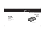
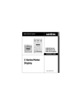
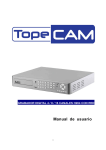
Figure 1 shows the AC panel of the 200 W unit.
OUTPUT: 115 VAC 60 HZ
160 W/1.4A Continuous
Figure 1 AC Panel of 200 W unit
An AC receptacle is located on one end of the 200 W unit. You can plug
in 120 V appliances with a combined total continuous power
consumption of 160 W or less when the inverter is turned on.
6
XP_Digital_200-400-800.book Page 7 Wednesday, October 26, 2005 2:51 PM
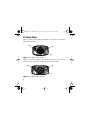
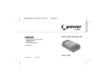
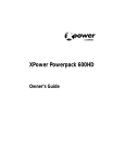
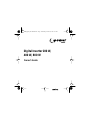
Figure 2 shows the AC panel of the 400 W unit, which is very similar to
the 800 W unit.
Figure 2 AC Panel of 400 W unit
Two AC receptacles are located on one end of the 400 W unit and the
800 W unit. You can plug in 120 V appliances with a combined total
continuous power consumption of 320 W (400 W unit) or 640 W
(800 W unit) or less when the inverter is turned on.
7
XP_Digital_200-400-800.book Page 8 Wednesday, October 26, 2005 2:51 PM
DC (Back) Panel
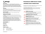
Figure 3 shows the DC panel of the 200 W unit. Use Table 1 to identify
the function of items.
2B
2A
1
Figure 3 DC Panel of 200 W unit
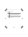
Figure 4 shows the DC panel of the 800 W unit, which is very similar to
the 400 W unit. Use Table 1 to identify the function of items.
2B
2A
1
Figure 4 DC Panel of 800 W unit
8
XP_Digital_200-400-800.book Page 9 Wednesday, October 26, 2005 2:51 PM
Table 1 DC Panel Functions
Item
Function
1
Fan and Ventilation Openings
The cooling fan on the units are designed to operate only when
output power is greater than approximately 80 W. When the inverter
is turned on, the fan may operate momentarily. The ventilation
openings should not be covered at any time while the inverter is
operating.
2
A) Positive and B) Negative Cabling Terminals
Connect the ring terminals on the power cables to these terminals. To
ensure correct polarity, red must be connected to red and black must
be connected to black.
9
XP_Digital_200-400-800.book Page 10 Wednesday, October 26, 2005 2:51 PM
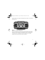
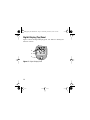
Digital Display (Top) Panel
Figure 5 shows the Digital Display panel. Use Table 2 to identify the
function of items.
3
2
1
Figure 5 Digital Display Panel
10
XP_Digital_200-400-800.book Page 11 Wednesday, October 26, 2005 2:51 PM
Table 2 Digital Display Panel Functions
Item
Function
1
Switch to turn the unit on and off.
Press to toggle the display function to show input voltage, output
power and output voltage.
2
Normal Operation
Digital display shows input voltage, output power and output
voltage.
Error Mode
Digital display shows error codes and alarm sounds when unit has
shut down due to under-voltage, over-voltage, over-load, overheating
or high-surge.
3
LEDs indicate the status of the digital display.
Audible Alarm
An audible alarm warns you if an under-voltage shutdown is about to
occur.
11
XP_Digital_200-400-800.book Page 12 Wednesday, October 26, 2005 2:51 PM
Types of Connections
Cable Clamps/Battery
Connections
Product
Lighter Plug Connection
200 W unit
Available – You must connect
a separate lighter plug cable
(included).
Not Available
400 W unit
Available – You must connect
a separate lighter plug cable
(included).
Available – You must connect
a separate battery clamp cable
(included).
800 W unit
Not Available
Available – You must connect
a separate battery clamp cable
(included).
12
XP_Digital_200-400-800.book Page 13 Wednesday, October 26, 2005 2:51 PM
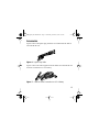
Accessories
Figure 6 shows the lighter plug cable that is included with the 200 W
unit and 400 W unit.
Figure 6 Lighter Plug Cable
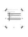
Figure 7 shows the cable supplied with the 400 W unit and 800 W unit
for direct connection to a 12 V battery.
Figure 7 Cable for Direct Connection to a 12 V Battery
13
XP_Digital_200-400-800.book Page 14 Wednesday, October 26, 2005 2:51 PM
4 Connecting the Digital Inverter
CAUTION
The Digital Inverter must only be connected to a battery that has a
nominal output of 12 V. It will not operate if connected to a 6 V battery
and may be damaged if connected to a battery with 16 V or more.
It is recommended that you hard wire the 800 W unit directly to the
12 V battery.
Choosing a Location
For best performance, place the inverter on a flat surface in a location
that is:
Dry
Cool
Do not expose the inverter to water, rain, snow or spray.
Operate the inverter in ambient temperatures between 0°C
and 40 °C (32 °F and 100 °F). Keep it away from heating
vents and direct sunlight.
Well-ventilated For proper cooling, allow at least 2 inches (5 cm) of
clearance around the inverter.
Clean and free of Choose a location that is free of any debris that could get
dust and dirt
into the inverter.
Safe
Do not install the inverter in a compartment with batteries
or flammable liquids, such as gasoline, or explosive vapors.
14
XP_Digital_200-400-800.book Page 15 Wednesday, October 26, 2005 2:51 PM
Connecting for Loads Under 150 W
Follow these steps to connect the 200 W unit or 400 W unit:
1. Place the inverter on a flat surface such as the floor of your vehicle.
2. Make sure that the unit is off by verifying the digital display is off.
3. Take the power cord equipped with the lighter plug (Figure 6) and
place the ring terminals over the two cabling terminals on the back
of the inverter. (The cabling terminals are shown in Figure 3 and
Figure 4.)
CAUTION: Reverse polarity
Power connections of the 12 V DC battery to the Digital Inverter must
be positive to positive and negative to negative.
A reverse polarity connection (positive to negative) will blow a fuse in
the inverter and may permanently damage the unit. Damage caused by a
reverse polarity connection is not covered by your warranty.
CAUTION
Make sure you connect red to red and black to black, and make sure you
screw the nuts on tightly.
4.
Fasten the positive (red) clamp to the positive battery post, and then
fasten the negative (black) clamp to the negative battery post.
15
XP_Digital_200-400-800.book Page 16 Wednesday, October 26, 2005 2:51 PM
5.
Tighten the nut on each DC terminal until it is snug. Do not
over-tighten.
6. Place the inverter’s lighter plug in the vehicle’s lighter socket or a
12 V outlet.
7. Turn on the unit by holding the switch located on top of the unit
until 888 is shown on the display.
The digital display will show the battery voltage, indicating that the
Digital Inverter is operating normally and AC power is available at
the outlet.
8. Plug in the AC product you want to operate.
When not in use always turn the inverter off by holding the switch until
the digital display turns off.
Connecting for Loads Over 150 W
You must connect the 400 W unit or 800 W unit directly to a 12 V
battery if you are going to operate loads greater than 150 W
continuously. When the inverter is connected this way, you can operate
loads of any size up to 320 W continuously with a 400 W unit and
640 W continuously with a 800 W unit.
16
XP_Digital_200-400-800.book Page 17 Wednesday, October 26, 2005 2:51 PM
WARNING: Shock hazard
Batteries contain corrosive materials and present an electrical shock
hazard. To prevent irritation and burns, wear protective eyewear and
clothing when you install the inverter or work with the batteries. Take
special care to ensure that metal tools and personal metal objects like
rings and bracelets do not contact the battery terminals.
Follow these steps to make a direct battery connection:
1. Place the inverter on a flat surface.
2. Make sure that the unit is off by verifying the digital display is off.
CAUTION: Reverse polarity
Power connections of the 12 V DC battery to the Digital Inverter must
be positive to positive and negative to negative.
A reverse polarity connection (positive to negative) will blow a fuse in
the inverter and may permanently damage the unit. Damage caused by a
reverse polarity connection is not covered by your warranty.
3.
Take the cables equipped with battery clamps on one end (Figure 7)
and place the ring terminals over the two cabling terminals on the
back of the inverter. (The cabling terminals are shown in Figure 3
and Figure 4.)
17
XP_Digital_200-400-800.book Page 18 Wednesday, October 26, 2005 2:51 PM
CAUTION
Make sure you connect red to red and black to black, and make sure you
screw the nuts on tightly.
4.
Fasten the positive (red) clamp to the positive battery post, and then
fasten the negative (black) clamp to the negative battery post.
5. Turn on the unit by holding the switch located on top of the unit
until 888 is shown on the display.
The digital display will show the battery voltage, indicating that the
Digital Inverter is operating normally and AC power is available at
the outlet.
6. Plug in the AC appliance you want to operate.
When not in use, always turn the inverter off by holding the switch until
the digital display turns off.
18
XP_Digital_200-400-800.book Page 19 Wednesday, October 26, 2005 2:51 PM
5 Operating the Digital Inverter
This section explains how to operate the Digital Inverter most
efficiently.
Operating Conditions and Guidelines
This section describes normal operation as well as conditions that
trigger an alarm or automatically shut down the Digital Inverter.
Normal Operation When you connect the inverter to the vehicle’s
lighter socket or directly to a 12 V battery and turn on the unit, the
digital display will show input voltage, the input voltage LED
illuminates and AC power is available at the outlets. You can now plug
in your AC products and turn them on one at a time.
Low Battery Alarm and Shutdown As the battery discharges, its
voltage decreases. When the Digital Inverter senses that the voltage at
its DC input has dropped to 11.0 V, it sounds an alarm, giving you time
to shut down sensitive loads such as computers. If you ignore the alarm,
and the DC input voltage drops below 10.5 V, the inverter shuts down
all loads to save the battery from further discharge. The under-voltage
error code ‘E01’ will show on the digital display.
19
XP_Digital_200-400-800.book Page 20 Wednesday, October 26, 2005 2:51 PM
High-input Voltage Shutdown If a defective battery charging system
causes the battery voltage to rise to dangerously high levels, the Digital
Inverter shuts down automatically. The over-voltage error code ‘E02’
will show on the digital display.
Overload Shutdown If you connect an AC load that is rated too high
(see Table 3) or a load that draws excessive surge power, the Digital
Inverter shuts down. The overload error code ‘E03’ will show on the
digital display.
Overheating Shutdown The Digital Inverter shuts down
automatically if it exceeds its safe operating temperature. The
overheating error code ‘E04’ will show on the digital display.
Shutting the inverter off
•
•
20
If you are going to disconnect the battery, turn the inverter off first.
Turn the inverter off by holding the switch until the display turns
off.
XP_Digital_200-400-800.book Page 21 Wednesday, October 26, 2005 2:51 PM
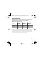
Operating normal loads
The Digital Inverter is capable of continuously powering most 120 V
AC products with the following power rating maximums:
Table 3 Power and Surge Ratings
Product
5 min Max.
Power Rating
Continuous
Power Rating
Surge Rating
Max.
200 W unit
200 W
160 W
400 W
400 W unit
400 W
320 W
700 W
800 W unit
750 W
640 W
1200 W
The inverter’s AC (“modified sine wave”) output waveform is designed
to function similarly to the sine wave shape of utility power. Most AC
products correctly rated for the power rating maximums listed in Table 3
or less will operate normally with the Digital Inverter.
21
XP_Digital_200-400-800.book Page 22 Wednesday, October 26, 2005 2:51 PM
Operating loads with high surge requirements
The power, or wattage rating, of AC loads is the average amount of
power they use. Some appliances consume more power than their power
rating when they are first turned on. TVs, monitors, and electric motors
are some products that have high surge requirements at start up. The
Digital Inverter can supply momentary surge power that is higher than
its maximum power rating. Some products rated less than power rating
maximum for your inverter may exceed its surge capability and trigger
an overload shutdown. If this problem occurs when attempting to
operate several AC products at the same time, try first turning on the
inverter with all AC products turned off, then one by one turn each on,
starting with the high-surge product first.
22
XP_Digital_200-400-800.book Page 23 Wednesday, October 26, 2005 2:51 PM
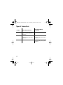
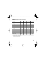
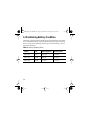
Table 4 Wattage of Common AC Products
Producta
Wattsb
200 W unit
400 W unit
800 W unit
Cell phone/camcorder
charger
10
Yes
Yes
Yes
Video game console
20
Yes
Yes
Yes
Portable work light
25
Yes
Yes
Yes
Stereo system
50
Yes
Yes
Yes
Laptop computer
75
Yes
Yes
Yes
13" TV
100
Yes
Yes
Yes
27" TV
200
Yes
Yes
20" TV/VCR combo
300
Yes
Small appliances
400+
Yes
Power tools
400+
Yes
Yes
a.Power requirements for product examples are estimates only. To calculate the wattage of a product, use
the following equation: amperage x 115.
b.If you want to power two or more products simultaneously, add the power requirements of both products to determine the total wattage.
23
XP_Digital_200-400-800.book Page 24 Wednesday, October 26, 2005 2:51 PM
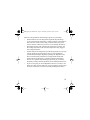
6 Maintaining Battery Condition
The battery operating time of the Digital Inverter depends on the charge
level of the battery, battery capacity, and the amount of power drawn by
the AC loads you are operating. With a typical vehicle battery, you can
expect the following:
Table 5 Battery Operating Times
Inverter
Load
Sample Appliance
Operating Time
200 W unit
50 W
CD player
6–8 hours
400 W unit
100 W
small TV
3–4 hours
800 W unit
200 W
TV/VCR
1–2 hours
24
XP_Digital_200-400-800.book Page 25 Wednesday, October 26, 2005 2:51 PM
Here are some guidelines that will help to preserve your battery:
• Vehicle batteries are not designed for repeated deep-discharge
cycles, and constantly recharging a vehicle’s battery will shorten its
life. Therefore, when you are using a vehicle battery as a power
source, start the vehicle every hour or two to recharge the battery.
• The Digital Inverter will operate while the engine is running, but
the voltage drop that occurs when the engine starts may trigger a
low-voltage shutdown.
• Vehicle batteries are designed to provide brief periods of very high
current needed for engine starting. They are not intended for
constant deep discharge. Regularly operating the Digital Inverter
from a vehicle battery until the low-voltage alarm sounds will
shorten the life of the battery. Consider connecting the Digital
Inverter to a separate deep discharge-type battery if you will be
frequently running electrical products for extended periods of time.
• If you are not going to use the Digital Inverter for a few days, turn
off the unit. The inverter draws 0.4 A or less when the unit is on and
no load is connected, but it will eventually discharge the battery.
25
XP_Digital_200-400-800.book Page 26 Wednesday, October 26, 2005 2:51 PM
7 Troubleshooting
This section will help you identify the source of most problems that can
occur with the Digital Inverter.
If you have a problem with the inverter, please review this section
before contacting your dealer. If you are unable to solve a problem and
need to contact service, please prepare for the call by writing down the
following details:
• Inverter’s serial number
• How long the inverter has been in use
• Where it is installed
• Appliances operating when the problem occurred
• A brief description of the problem
26
XP_Digital_200-400-800.book Page 27 Wednesday, October 26, 2005 2:51 PM
Common Problems
WARNING: Electrical shock and burn hazard
Do not disassemble the Digital Inverter. It does not contain any userserviceable parts. Attempting to service the inverter yourself could result
in an electrical shock or burn.
Buzz in audio systems
Some inexpensive stereo systems have inadequate internal power
supply filtering and buzz slightly when powered by the Digital Inverter.
The best solution is to use an audio system with a high-quality filter.
Television interference
The Digital Inverter is shielded to minimize interference with TV
signals. If TV signals are weak, you may see interference in the form of
lines scrolling across the screen. Try one of these suggestions to
minimize or eliminate the problem:
• Adjust the orientation of the Digital Inverter, television, antenna,
and cables.
• Maximize TV signal strength by using a better antenna, and use
shielded antenna cable where possible.
• Try a different TV. Different models vary considerably in their
susceptibility to interference.
27
XP_Digital_200-400-800.book Page 28 Wednesday, October 26, 2005 2:51 PM
Troubleshooting Reference
This section describes problems, their symptoms, possible causes, and
solutions.
Problem: The AC load will not operate. Digital display is off.
Possible Cause
Solution
Battery is defective.
Check battery and replace if required.
The inverter has been connected Check connection to battery.
with reverse DC input polarity. The inverter has likely been damaged and
needs to be repaired.
Have the unit repaired (not covered under
warranty).
Loose cable connections.
Check cables and connections.
Tighten as required.
Problem: The inverter will run some small loads, but not larger ones.
Possible Cause
Solution
Voltage drop across DC cables.
Shorten cables or use heavier cables.
28
XP_Digital_200-400-800.book Page 29 Wednesday, October 26, 2005 2:51 PM
Problem: Measured inverter output is too low.
Possible Cause
Solution
A standard “average-reading”
AC voltmeter has been used to
measure output voltage,
resulting in an apparent reading
5–15 V too low.
For accurate measurement, the Digital
Inverter modified sine wave output requires
a “true RMS” voltmeter for accurate
measurements.
The battery voltage is too low.
Recharge the battery.
Problem: Battery run time is less than expected.
Possible Cause
Solution
The AC product power
consumption is higher than
rated.
Use a larger battery to make up for the
increased power requirement.
The battery is old or defective.
Replace the battery.
The battery is not being charged Some chargers are not able to fully recharge
properly.
a battery. Make sure that you use a powerful
charger.
Power dissipation in DC cables. Use shorter/heavier DC cables.
29
XP_Digital_200-400-800.book Page 30 Wednesday, October 26, 2005 2:51 PM
Problem: The AC load will not operate, error code shows on digital
display and alarm is sounding.
Error
Possible Cause
Solution
E01
Low voltage shutdown because
battery is discharged.
Recharge battery.
Shorten cables or use heavier
cables.
E02
Over-voltage shutdown because Verify the charging system is
of high input voltage.
properly regulated and the battery
is 12 V nominal.
E03
The AC product(s) connected
are rated at more than the
inverter’s continuous power
rating; overload shutdown has
occurred.
Use a product with a power rating
within the inverter’s continuous
power rating (see Table 3).
E04
The inverter has overheated due
to poor ventilation.
Overheating shutdown has
occurred.
Turn inverter off and allow to cool
for 15 minutes. Clear blocked fan
or remove objects covering unit.
Move the inverter to a cooler
place. Reduce load if continuous
operation is required.
E05
The AC products connected
have a surge power that exceeds
the Digital Inverter’s surge
capability or the AC products
connected are short-circuited
and shutdown has occurred.
The products exceed the inverter’s
surge capability. Use a product
with a starting surge power within
the Digital Inverter’s capability.
30
XP_Digital_200-400-800.book Page 31 Wednesday, October 26, 2005 2:51 PM
8 Specifications
Specifications are subject to change without notice.
200 W unit
AC output voltage (nominal)
400 W unit
800 W unita
120 V AC
DC input voltage range
10.5–15.5 V DC
Maximum continuous AC
output power
160 W
320 W
640 W
5 minutes AC output power
200 W
400 W
750 W
Maximum AC output surge
power
400 W
700 W
1200 W
AC output frequency
60 ± 1 Hz
AC output waveform
Modified Sine Wave
No load current draw
(at 12 V input)
0.3 A
0.3 A
Efficiency (maximum)
0.4 A
90%
Ambient operating
temperature range
0–40 °C
Storage temperature
-20–60 °C
32–104 °F
-4–140 °F
31
XP_Digital_200-400-800.book Page 32 Wednesday, October 26, 2005 2:51 PM
200 W unit
400 W unit
800 W unita
Low voltage alarm
Low voltage shutdown
High voltage shutdown
11.0 V
10.5 V
15.5 V
11.0 V
10.5 V
15.5 V
11.0 V
10.5 V
15.5 V
Dimensions
(L × W × H)
102 × 84 × 51 mm
137 × 102 × 51 mm
141 × 114 × 61 mm
5
- × 2"
4 × 3 -----
5 5--- × 4 × 2"
7 1--- × 4 1--- × 2 3--- "
10 oz (0.28 kg)
1 lb (0.44 kg)
1 lb 13 oz (0.82 kg)
Weight
16
8
a.Provides maximum 800 watts of AC output power for up to 1 minute.
32
2
2
8
XP_Digital_200-400-800.book Page 33 Wednesday, October 26, 2005 2:51 PM
9 Warranty and Return
Warranty
What does this warranty cover? This Limited Warranty is provided by
Xantrex Technology Inc. ("Xantrex") and covers defects in workmanship and
materials in your Digital Inverter 200 W, 400 W, 800 W. This warranty period
lasts for six (6) months from the date of purchase at the point of sale to you, the
original end user customer. You require proof of purchase to make warranty
claims.
What will Xantrex do? Xantrex will, at its option, repair or replace the
defective product free of charge, provided that you notify Xantrex of the product
defect within the Warranty Period, and provided that Xantrex through inspection
establishes the existence of such a defect and that it is covered by this Limited
Warranty.
Xantrex will, at its option, use new and/or reconditioned parts in performing
warranty repair and building replacement products. Xantrex reserves the right to
use parts or products of original or improved design in the repair or replacement.
If Xantrex repairs or replaces a product, its warranty continues for the remaining
portion of the original Warranty Period or 90 days from the date of the return
shipment to the customer, whichever is greater. All replaced products and all
parts removed from repaired products become the property of Xantrex.
Xantrex covers both parts and labor necessary to repair the product, and return
shipment to the customer via a Xantrex-selected non-expedited surface freight
within the contiguous United States and Canada. Alaska and Hawaii are
excluded. Contact Xantrex Customer Service for details on freight policy for
return shipments outside of the contiguous United States and Canada.
33
XP_Digital_200-400-800.book Page 34 Wednesday, October 26, 2005 2:51 PM
How do you get service?
If your product requires troubleshooting or warranty service, contact your
dealer.
If you are unable to contact your dealer, or the dealer is unable to provide
service, contact Xantrex directly at:
Telephone: 1 360-925-5097
Fax:
1 360-925-5143
Web:
www.xantrex.com/support
Direct returns may be performed according to the Xantrex Return Material
Authorization Policy described in your product manual. For some products,
Xantrex maintains a network of regional Authorized Service Centers. Call
Xantrex or check our website to see if your product can be repaired at one of
these facilities.
What proof of purchase is required? In any warranty claim, dated proof of
purchase must accompany the product and the product must not have been
disassembled or modified without prior written authorization by Xantrex.
Proof of purchase may be in any one of the following forms:
•
The dated purchase receipt from the original purchase of the product at
point of sale to the end user, or
•
The dated dealer invoice or purchase receipt showing original equipment
manufacturer (OEM) status, or
•
The dated invoice or purchase receipt showing the product exchanged
under warranty
34
XP_Digital_200-400-800.book Page 35 Wednesday, October 26, 2005 2:51 PM
What does this warranty not cover? This Limited Warranty does not cover
normal wear and tear of the product or costs related to the removal, installation,
or troubleshooting of the customer's electrical systems. This warranty does not
apply to and Xantrex will not be responsible for any defect in or damage to:
a) the product if it has been misused, neglected, improperly installed, physically damaged or altered, either internally or externally, or damaged from
improper use or use in an unsuitable environment;
b) the product if it has been subjected to fire, water, generalized corrosion,
biological infestations, or input voltage that creates operating conditions
beyond the maximum or minimum limits listed in the Xantrex product
specifications including high input voltage from generators and lightning
strikes;
c) the product if repairs have been done to it other than by Xantrex or its
authorized service centers (hereafter "ASCs");
d) the product if it is used as a component part of a product expressly warranted by another manufacturer;
e) the product if its original identification (trade-mark, serial number) markings have been defaced, altered, or removed.
Disclaimer
Product
THIS LIMITED WARRANTY IS THE SOLE AND EXCLUSIVE WARRANTY
PROVIDED BY XANTREX IN CONNECTION WITH YOUR XANTREX PRODUCT
AND IS, WHERE PERMITTED BY LAW, IN LIEU OF ALL OTHER WARRANTIES,
CONDITIONS, GUARANTEES, REPRESENTATIONS, OBLIGATIONS AND
LIABILITIES, EXPRESS OR IMPLIED, STATUTORY OR OTHERWISE IN
35
XP_Digital_200-400-800.book Page 36 Wednesday, October 26, 2005 2:51 PM
CONNECTION WITH THE PRODUCT, HOWEVER ARISING (WHETHER BY
CONTRACT, TORT, NEGLIGENCE, PRINCIPLES OF MANUFACTURER'S
LIABILITY, OPERATION OF LAW, CONDUCT, STATEMENT OR OTHERWISE),
INCLUDING WITHOUT RESTRICTION ANY IMPLIED WARRANTY OR
CONDITION OF QUALITY, MERCHANTABILITY OR FITNESS FOR A
PARTICULAR PURPOSE. ANY IMPLIED WARRANTY OF MERCHANTABILITY
OR FITNESS FOR A PARTICULAR PURPOSE TO THE EXTENT REQUIRED
UNDER APPLICABLE LAW TO APPLY TO THE PRODUCT SHALL BE LIMITED
IN DURATION TO THE PERIOD STIPULATED UNDER THIS LIMITED
WARRANTY.
IN NO EVENT WILL XANTREX BE LIABLE FOR ANY SPECIAL, INDIRECT,
INCIDENTAL OR CONSEQUENTIAL DAMAGES, LOSSES, COSTS OR EXPENSES
HOWEVER ARISING WHETHER IN CONTRACT OR TORT INCLUDING
WITHOUT RESTRICTION ANY ECONOMIC LOSSES OF ANY KIND, ANY LOSS
OR DAMAGE TO PROPERTY, ANY PERSONAL INJURY, ANY DAMAGE OR
INJURY ARISING FROM OR AS A RESULT OF MISUSE OR ABUSE, OR THE
INCORRECT INSTALLATION, INTEGRATION OR OPERATION OF THE
PRODUCT.
Exclusions
If this product is a consumer product, federal law does not allow an exclusion of
implied warranties. To the extent you are entitled to implied warranties under
federal law, to the extent permitted by applicable law they are limited to the
duration of this Limited Warranty. Some states and provinces do not allow
limitations or exclusions on implied warranties or on the duration of an implied
warranty or on the limitation or exclusion of incidental or consequential
36
XP_Digital_200-400-800.book Page 37 Wednesday, October 26, 2005 2:51 PM
damages, so the above limitation(s) or exclusion(s) may not apply to you. This
Limited Warranty gives you specific legal rights. You may have other rights
which may vary from state to state or province to province.
Warning: Limitations On Use
Please refer to your product manual for limitations on uses of the product.
SPECIFICALLY, PLEASE NOTE THAT THE DIGITAL INVERTER 200 W, 400 W,
800 W SHOULD NOT BE USED IN CONNECTION WITH LIFE SUPPORT
SYSTEMS OR OTHER MEDICAL EQUIPMENT OR DEVICES. WITHOUT
LIMITING THE GENERALITY OF THE FOREGOING, XANTREX MAKES NO
REPRESENTATIONS OR WARRANTIES REGARDING THE USE OF THE
XANTREX DIGITAL INVERTER 200 W, 400 W, 800 W IN CONNECTION WITH
LIFE SUPPORT SYSTEMS OR OTHER MEDICAL EQUIPMENT OR DEVICES.
Return Material Authorization Policy
Before returning a product directly to Xantrex you must obtain a Return
Material Authorization (RMA) number and the correct factory "Ship To"
address. Products must also be shipped prepaid. Product shipments will be
refused and returned at your expense if they are unauthorized, returned without
an RMA number clearly marked on the outside of the shipping box, if they are
shipped collect, or if they are shipped to the wrong location.
37
XP_Digital_200-400-800.book Page 38 Wednesday, October 26, 2005 2:51 PM
When you contact Xantrex to obtain service, please have your instruction
manual ready for reference and be prepared to supply:
•
The serial number of your product
•
Information about the installation and use of the unit
•
Information about the failure and/or reason for the return
•
A copy of your dated proof of purchase
38
XP_Digital_200-400-800.book Page 39 Wednesday, October 26, 2005 2:51 PM
Return Procedure
1.
2.
3.
Package the unit safely, preferably using the original box and packing
materials. Please ensure that your product is shipped fully insured in the
original packaging or equivalent. This warranty will not apply where the
product is damaged due to improper packaging.
Include the following:
• The RMA number supplied by Xantrex Technology Inc. clearly
marked on the outside of the box.
• A return address where the unit can be shipped. Post office boxes are
not acceptable.
• A contact telephone number where you can be reached during work
hours.
• A brief description of the problem.
Ship the unit prepaid to the address provided by your Xantrex customer
service representative.
If you are returning a product from outside of the USA or Canada In
addition to the above, you MUST include return freight funds and are fully
responsible for all documents, duties, tariffs, and deposits.
If you are returning a product to a Xantrex Authorized Service Center
(ASC) A Xantrex return material authorization (RMA) number is not required.
However, you must contact the ASC prior to returning the product or presenting
the unit to verify any return procedures that may apply to that particular facility.
39
XP_Digital_200-400-800.book Page 40 Wednesday, October 26, 2005 2:51 PM
Out of Warranty Service
If the warranty period for your Digital Inverter 200 W, 400 W, 800 W has
expired, if the unit was damaged by misuse or incorrect installation, if other
conditions of the warranty have not been met, or if no dated proof of purchase is
available, your unit may be serviced or replaced for a flat fee.
To return your Digital Inverter 200 W, 400 W, 800 W for out of warranty
service, contact Xantrex Customer Service for a Return Material Authorization
(RMA) number and follow the other steps outlined in “Return Procedure” on
page 39.
Payment options such as credit card or money order will be explained by the
Customer Service Representative. In cases where the minimum flat fee does not
apply, as with incomplete units or units with excessive damage, an additional fee
will be charged. If applicable, you will be contacted by Customer Service once
your unit has been received.
10 Other Xantrex Products
To see the range of inverters and chargers offered by Xantrex, visit our
web site at www.xantrex.com.
40