1
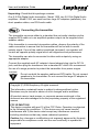
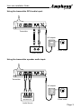
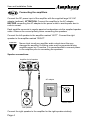
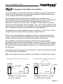
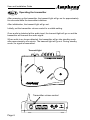
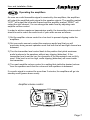
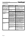
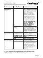
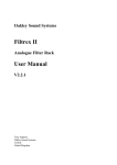
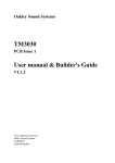
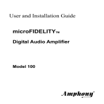
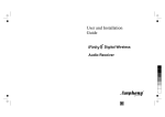
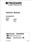
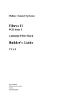
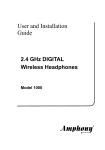
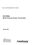
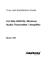
User and Installation Guide
5.8 GHz DIGITAL Wireless
Audio Transmitter / Amplifier
Model 1550
R
Contents
Unpacking ....................................................................................... 2
Connecting the transmitter .............................................................. 2
Connecting the amplifiers ............................................................... 4
Placing the transmitter and amplifiers ............................................. 5
Operating the transmitter ................................................................ 6
Operating the amplifiers ................................................................. 7
Troubleshooting .............................................................................. 8
Technical specifications ................................................................ 10
Safety information ......................................................................... 11
Your warranty ................................................................................ 12
User and Installation Guide
R
Unpacking: Check that this package contains:
One 5.8 GHz Digital Audio transmitter - Model 1550, two 5.8 GHz Digital Audio
amplifiers - Model 1550, one small and two large AC adapters (wallwarts), four
short speaker cables, one RCA audio cable.
Step 1
Connecting the transmitter
The transmitter connects either to a standard line-out audio interface via the
supplied RCA cable or to an amplified speaker output via the supplied short
speaker cables.
If the transmitter is connected via speaker cables, observe the polarity of the
cable connection to ensure that the transmitter will be fed with a correct
polarity signal. If one of the cables is switched (reversed), one speaker will
receive an opposite polarity signal which will degrade sound performance.
The transmitter can also be connected to other audio outputs by using an
appropriate adapter.
Connect the supplied small AC adapter’s barrel-shaped plug into the DC 9V
jack, and then plug the transformer into a standard AC outlet. We recommend
the use of a surge protector to protect the transmitter from power surges.
ATTENTION!
Do not use both the speaker cables and RCA cable. Do not connect
speakers to the transmitter. Do not connect the large AC adapter to
the transmitter.
Copyright (C) 2008 Amphony. All rights reserved.
The information contained herein is subject to change without notice.
Revisions may be issued to advise of such changes and/or additions.
All product names, trade names, or corporate names mentioned in this
document are acknowledged to be the proprietary property of the registered
owners.
FCC ID PMJT1500
This device complies with part 15 of the FCC Rules. Operation is subjected
to the following two conditions: 1) This device may not cause harmful
interference and 2) this device must accept any interference received,
including interference that may cause undesired operation.
Caution: Any changes or modifications not expressly approved by the party
responsible for compliance could void the user's authority to operate the
equipment.
R
User and Installation Guide
Using the transmitter RCA audio input:
L
R
DC 9V
L
R
Transmitter
AC adapter
DC 9 V
300 mA
AUDIO
LINE OUT
L
Power outlet
R
Audio Source
Using the transmitter speaker audio input:
L
R
DC 9V
L
R
Transmitter
AC adapter
DC 9 V
300 mA
L
R
SPEAKER OUT
Audio Source
Power outlet
Page 3
R
User and Installation Guide
Step 2
Connecting the amplifiers
Connect the DC power input of the amplifier with the supplied large 24 V AC
adapter (wallwart). ATTENTION: Connect the amplifier to the AC adapter
BEFORE connecting the AC adapter to the power outlet to avoid sparks due to
rush-in current.
Each amplifier connects to regular passive loudspeakers via the supplied speaker
cable. Observe the correct polarity when connecting the speakers.
Connect the left speaker to the amplifier marked “LEFT”. Connect the right
speaker to the amplifier marked “RIGHT”.
ATTENTION!
Never short circuit any amplifier audio output since this may
damage the amplifier. A clicking noise may be generated during
amplifier power up. Therefore, it is recommended to connect power
to the amplifier prior to connecting the speakers.
Speaker connections:
Amplifier for left speaker
AC adapter
DC 24 V
1000 mA
Power outlet
Left speaker
Connect the right speaker to the amplifier for the right speaker similarly.
Page 4
R
User and Installation Guide
Step 3
Placing the transmitter and amplifiers
For best reception, we recommend that each amplifier be placed within the line
of sight from the transmitter. If possible, each amplifier should be placed right
side up with its front toward the transmitter.
The transmitter should be placed at an elevation such that there are no
obstacles between the transmitter and amplifiers (line of sight) in an area where
there will be the least amount of traffic. We suggest that you place the
transmitter on top of your audio source. Example 1 below shows the optimum
placement of the transmitter and an amplifier. If no line of sight is possible, place
the transmitter and amplifiers such that there is the minimum possible number of
walls and obstacles between the transmitter and each amplifier.
The amplifiers can also be placed as shown in example 2. In this case, no lineof-sight connection exists and the operating range is reduced.
You can mount the amplifiers vertically by using the 2 screw openings at the
bottom of each amplifier. If the amplifiers are mounted vertically, the operating
range is reduced compared to mounting the amplifiers right side up.
Each amplifier incorporates a directional antenna which prefers signals
transmitted toward the front of the amplifier. Therefore, the front of the amplifiers
should always be facing toward the direction of the strongest transmitter signal.
By properly orienting each amplifier, interference from other signal sources can
be minimized.
We suggest that you experiment with placement in order to find the best location
for the transmitter and amplifiers.
Note: This product will not work properly from within an enclosed metal cabinet.
Transmitter
Transmitter
line of sight
Amplifier
Speaker
Example 1: Amplifier placed
on top of a speaker
indirect connection
(reflected signal)
Amplifier
Speaker
Example 2: Amplifier mounted
vertically behind a speaker
Page 5
R
User and Installation Guide
Step 4
Operating the transmitter
After powering up the transmitter, the transmit light will go on for approximately
five seconds while the transmitter initializes.
After initialization, the transmit light will go out.
Initially, set the transmitter volume control to a middle setting.
Once audio is detected at the audio input, the transmit light will go on and the
transmitter will transmit the audio signal.
When audio is no longer detected, the transmitter will go into standby mode
after approximately one minute. The transmit light will go out. During standby
mode, no signal is transmitted.
Transmit light
TR
A
N
S
M
IT
5.8 GHz Digital Audio Transmitter
R
Transmitter volume control
L
R
DC 9V
L
Page 6
R
R
User and Installation Guide
Step 5
Operating the amplifiers
As soon as a valid transmitter signal is received by the amplifiers, the amplifiers
will output the amplified audio signal to the speaker outputs. The amplfier marked
“LEFT” will output the left audio channel and the amplifier marked “RIGHT” will
output the right channel. You can change the audio level by adjusting each
amplifier volume control.
In order to achieve maximum transmission quality, the transmitter volume control
should be set to match the audio level of your audio source as follows:
1) Set the amplifier volume control to a low level to prevent clipping inside the
amplifiers.
2) Set your audio source to output the maximum audio level that you will
encounter during normal operation such that both the left and right channel are
balanced.
3) Turn the transmitter level control knob to the position that yields maximum
audio loudness to the speakers without any clipping (distortion). If the
transmitter level is set too low, the dynamics of the transmission are not fully
used. If the level is set too high, audio clipping (distortion) will occur inside
the transmitter.
4) Turn each amplifier volume control to a setting that yields the desired volume
from the speakers such that the volume at both speakers is balanced.
If no audio signal is received for more than 2 minutes, the amplifiers will go into
standby mode (power-down mode).
Amplifier volume control
Page 7
R
User and Installation Guide
Troubleshooting
Proble m
The transmit light
do es not go on after
DC power is applied
to the transmitter
The transmit light
go es out after a few
seco nds and does
no t li ght again
Possible Cause
Solution
Faulty AC adapter
Check the power outlet and
or faulty power outlet the AC adapter; if possible,
check for correct voltage of
the AC adapter.
No audio present at
Check the audio connection
audio input
to the transmitter and ensure
that there is audio present.
Tran smitter hung up Disconnect and then
reconnect DC power.
No a udio at
Faulty AC adapter
See under “Faulty AC adapter
amplifie r
or faulty power outlet or faulty power outlet“ above.
Tran smitter volume
Adjust the transmitter volume
control set too low
control.
Amplifier volume
Adjust the amplifier volume
control set too low
control.
Strong interference
See under “Strong
Interference“ on next page.
Aud io is distorted
Tran smitter volume
Adjust the transmitter volume
control set too high
control until clipping stops.
Amplifier volume
Adjust the amplifier volume
control set too high
control until clipping stops.
Strong interference
See under “Strong
Interference“ on next page.
Spe aker audio level Tran smitter volume
Adjust the transmitter volume
is too lo w
control set too low
control to achieve desired
audio level.
Amplifier volume
Adjust the amplifier volume
control set too low
control to achieve desired
audio level.
Audio signal too
Increase the output level of
weak
the audio source (connect
transmitter to an adjustable
output by using an adapter if
necessary).
Page 8
R
User and Installation Guide
Problem
Possible Cause
Solution
Audio drops out
intermittently or
crackles
Strong interference
In some cases, there may be
strong interference preventing
pro per reception of the audio
signal which can be caused
by 5.8 GHz cordless
telephones or 5.8 GHz
wireless n etworks. Either
el iminate the interference,
lo cate the base unit of the
cordless phone in another
roo m, set the wireless
ne twork to use the 5.1 GHz
frequency band rather than
5.8 GHz, re locate the
transmitter, relocate or
reo rien t the amplifier to
improve reception.
Ensure that the powe r outlet
de livers a stable voltage. Very
strong surges or voltage
fluctuati ons may cause audio
dro pouts. Try using a surge
pro tector.
See under “Strong
Interference“ above.
Adj ust the transmitter volume
contro l.
See under “Audio signal too
weak“ on previous page.
See under “Strong
Interference“ above.
Aud io wi ll drop out if there are
too many obstacles betwee n
the transmitter and the
amplifie r (se e page 4), try
rel ocating the amplifier or
transmitter to improve
reception.
Unstable power
supply
Audio is noisy
Strong interference
Transmitter volume
control set too low
Audio signal too
weak
Transmitter range is Strong interference
extremely short
Too many obstacles
For more information, including a detailed troubleshooting guide,
visit the Amphony web site at: www.amphony.com
Page 9
User and Installation Guide
Technical Specifications
Transmitter:
Audio transmission method: Digital
Transmitter frequency: 5.8 GHz
Error correction: 1/2 rate FEC
Audio sampling method: 128 times oversampling
Transmitted data rate: > 3 Mbps
Transmitter operating range:
max. 200 ft. line of sight, max. 50 ft. through walls and ceilings
Amplifier:
Output power: 50 W (30 Wrms)
Frequency response: 2 Hz … 23 kHz
Signal-to-noise ratio: 91 dB (Transmitter / Amplifier, A-weighted)
Total harmonic distortion: typ. 0.05 %
Overall audio latency: < 1 ms
Power efficiency: 75 %
Channel separation: typ. 94 dB
Automatic amplifier power down feature
Page 10
R
R
User and Installation Guide
IMPORTANT SAFETY INFORMATION
ATTENTION!
READ THESE SAFETY INSTRUCTIONS CAREFULLY AND HEED ALL
WARNINGS IN THIS MANUAL.
POWER SOURCE
To product malfunction, and to protect against electric shock, fire or personal injury,
please observe the following:
• This product has been designed to work with 120-volt AC current using the supplied
AC adapters. Connection to a line voltage other than that or use of non-compatible
AC adapters may create a safety and fire hazard and may damage the product.
• Do not run power cords under rugs or carpets or place heavy objects on them.
• Damaged or deformed power cords are hazardous and should be replaced
immediately by a qualified service technician.
LOCATION
• Do not use this product outdoors or in cars.
• Air vents are provided at the bottom of the amplifier to prevent excessive temperatures inside the unit. Do not place the amplifier in closed spaces, cover it, or otherwise
block the vents.
• Do not place this product in direct sunlight, or near heat sources.
• Keep this product away from strong magnetic objects.
VOLUME CONTROL
• Do not turn up the volume while listening to a portion with very low level input or no
audio signal to avoid damage to your speakers during a peak level audio portion.
• Turn the amplifier volume control to minimum prior to connecting or disconnecting the
transmitter or amplifier and prior to switching audio sources as this may cause loud
clicks which can damage your speakers.
CARE
• Do not insert or drop anything into the amplifier through the air vents as this could
cause serious damage, possibly resulting in fire.
• Do not place any object containing water or other liquids on this product.
• Do not remove the cabinet. Touching parts inside the cabinet could result in electric
shock and damage to the product.
NON-USE PERIODS
• When the product is not being used for a long period of time, unplug the product.
CLEANING
• Unplug the product before cleaning.
• When the system gets dirty, wipe it with a clean, soft cloth. If necessary, wipe it with a
soft cloth, slightly dampened with soapy water. Wipe dry immediately with a dry cloth.
• Never use benzene, aerosol cleaners, thinner, alcohol or any volatile cleaning agent.
• Do not use abrasive cleaners, as they may damage the finish.
SERVICE
• Do not open the cabinet of any components. Opening the cabinets may present a
shock hazard, and any modification to this product will void your warranty.
• Do not attempt to service the unit yourself. If liquid or any metal objects such as paper
clips, wire or staples accidentally fall inside, disconnect the product from the power
source immediately, and consult an authorized service center.
• Please refer any service to an authorized Amphony service center.
Limited warranty
WHAT YOUR WARRANTY COVERS
This warranty extends only to the original user of the equipment (“you”, ”your”) and is limited to the
purchase price of each part. Amphony and its affiliated companies (”we”, ”our”, ”us”) warrant this Wireless
Transmitter / Amplifier Set against defects in materials or workmanship as follows.
LABOR: For a period of ninety (90) days from the original date of purchase, if we determine that the
equipment is defective subject to the limitations of this warranty, we will replace it at no charge for labor.
We warrant any such work done against defects in materials or workmanship for the remaining portion of
the original warranty period.
PARTS: For a period of one (1) year from the original date of purchase, we will supply, at no charge, new
or rebuilt replacement parts in exchange for parts we determine are defective subject to the limitations of
this warranty. We warrant any such replacement parts against defects in materials or workmanship for
the remaining portion of the original warranty period.
Note: ”Parts” means items included in this package. It does not include other parts purchased separately.
WHAT YOUR WARRANTY DOES NOT COVER
This warranty does not cover consumer instruction, physical setup or adjustment of any consumer
electronic equipment, or signal transmission problems.
This warranty does not cover cosmetic damage, damage due to the affixing of any attachment not
provided with the product, loss of parts, connecting the product to any but the specified receptacles,
lightning, electrical surges, fire, flood, or other acts of God, accident, misuse, abuse, repair or alteration
by other than authorized service personnel, negligence, commercial or institutional use, or improper or
neglected maintenance.
This warranty does not cover equipment sold AS IS or WITH ALL FAULTS, equipment removal or
reinstallation, shipping damage if the equipment was not packed and shipped in the manner we
prescribe, nor equipment purchased, serviced, or operated outside the contiguous United States of
America.
LEGAL LIMITATIONS
REPLACEMENT AS PROVIDED UNDER THIS WARRANTY IS YOUR EXCLUSIVE REMEDY. WE
SHALL NOT BE HELD LIABLE FOR ANY INCIDENTAL OR CONSEQUENTIAL DAMAGES FOR
BREACH OF ANY EXPRESSED OR IMPLIED WARRANTY ON THIS EQUIPMENT, NOR FOR ANY
INCIDENTAL OR CONSEQUENTIAL DAMAGES RESULTING FROM THE USE OF, OR INABILITY TO
USE, THIS EQUIPMENT. UNDER NO CIRCUMSTANCES SHALL OUR LIABILITY, IF ANY, EXCEED
THE PURCHASE PRICE PAID FOR THIS EQUIPMENT, EXCEPT TO THE EXTENT PROHIBITED BY
APPLICABLE LAW. EXCEPT AS PROVIDED HEREIN, WE MAKE NO WARRANTIES, EXPRESS OR
IMPLIED, INCLUDING WARRANTIES OF MERCHANTABILITY AND FITNESS FOR A PARTICULAR
PURPOSE. WE RESERVE THE RIGHT TO REFUSE TO HONOR THIS WARRANTY IF WE
DETERMINE ANY OF THE ABOVE EXCEPTIONS TO HAVE CAUSED THIS EQUIPMENT NOT TO
HAVE PERFORMED PROPERLY. THIS WARRANTY SHALL BE VOID IF ANY FACTORY-APPLIED
IDENTIFICATION MARK, INCLUDING BUT NOT LIMITED TO SERIAL NUMBERS AND WARRANTY
LABELS, HAS BEEN ALTERED OR REMOVED. THIS WARRANTY SHALL ALSO BE VOID IF THE
TRANSMITTER OR AMPLIFIER HAVE BEEN OPENED BY AN UNAUTHORIZED PERSON.
This warranty gives you specific legal rights which may vary from state to state. Some states do not allow
the exclusion or limitation of incidental or consequential damages, or allow limitations on the duration of
an implied warranty, so those limitations may not apply to you.
Note: No responsibility is assumed for the presence of interference outside of Amphony’s control, such
as other transmitters or cordless phones, which may hamper proper signal reception.