1
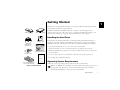
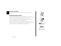
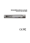
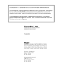
ATA Hard Drive
Installation
Guide
Copyright
© 2002 Maxtor Corporation. All rights reserved. Changes are periodically made to the information herein which will be incorporated in revised editions of this publication. Maxtor may make changes
or improvements to the product(s) described in this publication at any time and without notice. MaxBlast is a trademark and Maxtor is a registered trademark of Maxtor Corporation. All other brands
or products are trademarks or registered trademarks of their respective holders.
FCC Declaration of Conformance
This device complies with part 15 of the FCC Rules. Operation is subject to the following two conditions: (1) this device may not cause harmful interference, and (2) this device must accept any
interference received including interference that may cause undesired operation.
Maxtor Corporation
500 McCarthy Blvd., Milpitas, California 95035 USA
Part Number
20186800/A
P/N: 20186800/A
Contents
1 Getting Started
...................................1
Handling the Hard Drive. . . . . . . . . . . . . . . . . . . . . . . . . . . . . . . . . . . . .
Operating System Requirements . . . . . . . . . . . . . . . . . . . . . . . . . . . . . . .
Back Up Your Data . . . . . . . . . . . . . . . . . . . . . . . . . . . . . . . . . . . . . . . .
Important Capacity Notice . . . . . . . . . . . . . . . . . . . . . . . . . . . . . . . . . . .
1
1
2
2
2 Installing the Hard Drive . . . . . . . . . . . . . . . . . . . . . . . . 3
Removing the System Cover . . . . . . . . . . . . . . . . . . . . . . . . . . . . . . . . . . 3
Setting the Jumpers . . . . . . . . . . . . . . . . . . . . . . . . . . . . . . . . . . . . . . . . . 4
Mounting the Hard Drive . . . . . . . . . . . . . . . . . . . . . . . . . . . . . . . . . . . . 7
Attaching the Cables . . . . . . . . . . . . . . . . . . . . . . . . . . . . . . . . . . . . . . . . 9
Configuring the System BIOS . . . . . . . . . . . . . . . . . . . . . . . . . . . . . . . . 12
3 Formatting the Hard Drive
. . . . . . . . . . . . . . . . . . . . 15
Installing Hard Drive as a Boot Drive . . . . . . . . . . . . . . . . . . . . . . . . . . . 16
Installing Hard Drive to Replace Existing Hard Drive. . . . . . . . . . . . . . . 20
Installing Hard Drive as an Additional Hard Drive . . . . . . . . . . . . . . . . . 21
4 Getting Help . . . . . . . . . . . . . . . . . . . . . . . . . . . . . . . . . . . . . .
23
Installation Troubleshooting . . . . . . . . . . . . . . . . . . . . . . . . . . . . . . . . . 23
Frequently Asked Questions . . . . . . . . . . . . . . . . . . . . . . . . . . . . . . . . . 25
5 Glossary
. . . . . . . . . . . . . . . . . . . . . . . . . . . . . . . . . . . . . . . . . . . 27
Maxtor Product Warranty. . . . . . . . . . . . . . . . . . . . . .
30
Getting Started
1
Thank you for selecting a Maxtor hard drive storage product. This installation guide will lead
you through the installation of your hard drive.
Maxtor ATA Hard Drive
ATA Interface Cable
The Maxtor Hard Drive Retail Kit includes the components shown in Figure 1.Your
computer may need some or all of these parts to complete the installation.You will also need
the tools shown in Figure 2 on page 2 to install the hard drive in your computer.
Handling the Hard Drive
Max•Blast Plus II
TM
Hard Drive Installation Software
MaxBlast Plus II
Installation Disk
MaxBlast Plus II
Installation CD
Your hard drive should be handled with care during unpacking and installation. Damage to
hard drives is typically caused by rough handling, shock, vibration, or electrostatic discharge
(ESD). Be aware of the following precautions when unpacking and handling your hard drive:
• Save the packing materials in case you need to return your hard drive.
• Allow the hard drive to reach room temperature before opening the anti-static bag.
Installation Guide
(not included with all kits)
Mounting Screws
• Handle the hard drive by its sides. Do not touch the circuit board electronics on the bottom
of the hard drive.
• Do not connect or disconnect any hard drive cables when the system is powered on.
• Do not drop, jar, or bump the hard drive.
Operating System Requirements
5.25-inch Mounting Brackets
(not included with all kits)
Quick Start Poster
Figure 1. Included in this Kit
A full version of your operating system is required to install a new hard drive.
Windows 98, ME, NT, 2000 and XP (before SP1), and Mac OS operating systems do not
properly support the full capacity of an internal hard drive larger than 137 GB. See
“Formatting the Hard Drive” on page 15 for more information.
Getting Started
1
1
Back Up Your Data
Protect your data by backing up existing hard drives before installing your new Maxtor
hard drive.
Important Capacity Notice
System Ma
nual
System User Manual
If you are installing this hard drive without an Ultra/ATA PCI adapter card, be sure that your
computer meets the system requirements printed on the Maxtor box. Some older systems
require the use of an ATA card to fully recognize higher capacity hard drives.
If you are installing this hard drive with an Ultra/ATA PCI adapter card, use the ATA card
documentation to install the card before installing the hard drive.
Maxtor recommends that all customers use the MaxBlast™ Plus II installation software, rather
than FDISK, to partition and format the hard drive. See “Frequently Asked Questions” on
page 25 for more information on the MaxBlast Plus II formatting utility.
Operating System
CD and/or Boot Disk
Phillips Screwdriver
Small Needle-Nose Pliers
Figure 2. Required Tools
2
Getting Started
Installing the Hard Drive
This chapter describes how to physically install the hard drive in your computer. The
installation steps are as follows:
2
• Remove the system cover.
• Set the jumpers.
• Mount the hard drive in your computer.
• Attach the cables.
• Configure the BIOS (Windows-based systems only).
Removing the System Cover
For Macintosh systems, refer to the documentation that came with your system or go to
www.apple.com/support for information about opening your system case.
1. Turn your computer off.
Leave the computer powered off and plugged into an electrical outlet to keep the
system grounded.
2. Remove the cover from your system case. Refer to your computer system user manual
for instructions on removing the cover, or obtain the services of a qualified installation
technician.
3. Attach a grounding strap or touch a metal portion of your computer case. This
will ground you to minimize the risk of exposing the hard drive to electrostatic discharge.
Figure 3. Removing the System Cover
Installing the Hard Drive
3
Setting the Jumpers
2
A jumper is a small plastic piece that slides over a pair of configuration pins. (See Figure 4.)
The next step in the installation process is to set the jumpers on the back of your hard drive so
your system can identify the hard drive.
The following definitions describe the jumper settings:
Master. This setting can be used if you will be using the new hard drive as a primary master
boot drive or a secondary master additional storage drive. The hard drive should be connected
to the black (master) connector at the end of the ATA cable.
Slave. This setting can be used if you will be using the new hard drive for additional storage
only and is not typically used for boot devices on Windows-based systems. The hard drive
should be connected to the gray (middle) connector on the ATA cable.
Cable Select. This setting is an alternate method of hard drive identification that can be used
instead of the master and slave settings. With cable select enabled, all hard drives positioned on
the black (master) connector of the ATA cable will identify as master, and all hard drives
positioned on the gray (middle) connector will identify as slave.
To properly configure cable select, all devices on the same ATA cable must use the cable select
jumper setting and be connected with an 40-pin Ultra ATA cable like the one included.
Before installing a new hard drive, Maxtor recommends that you check to see if any device
currently attached to the ATA cable you wish to use is configured as cable select.You may need
to consult the documentation for this device or its manufacturer for jumper configuration
information.
"
4
Older systems that do not support Ultra ATA/66 speeds or are dated prior to November
1998 may not be able to use the cable select jumper option. If you are uncertain whether
your system can use the cable select option, use the master/slave settings instead.
Installing the Hard Drive
Figure 4. A Jumper
Determining the Correct Jumper Setting
The correct jumper setting for your hard drive depends on your current system configuration
and how you want to use the new hard drive. The recommended jumper settings below will
work on many, but not all, systems.
2
• If you are building a new system, use the cable select setting on all ATA devices to make it
easier to configure your system.
• If you have an existing system, check the jumper settings on your current boot drive and
your CD-ROM drive. If these drives are using master/slave jumper settings, use the master/
slave jumper settings on your new hard drive. If your current boot drive and CD-ROM
drive are using the cable select setting, use cable select on the new hard drive.
R AT I O N
PO
•
D DIS
A XTO
R
•M
AR
C
R
H
O
D
R
IV
Y
K
6B
e: M20
war
Firm
51
1273
E
•
Q UA
LIT
80GB
MP
P/N:
city
Capa l
Leve
Jumper Style A
"
Internal CD-ROM, DVD, Zip, and Jaz drives with an ATA interface are known as ATAPIcompliant devices. If the new hard drive is being attached to a cable to which an ATAPI
drive is already attached, you should configure the hard drive as master and the ATAPI
device as slave OR both devices as cable select, with the ATAPI device attached to the
gray connector on the ATA cable. To avoid potential issues with hard drive detection and
performance, Maxtor does not recommend attaching a hard drive as a slave on the same
cable as an ATAPI device. (For cable configuration, see “Existing System 3” on page 11.)
To determine your hard drive’s jumper style
1. Remove the hard drive from its anti-static bag.
or
Jumper Styles B & C
2. Locate the jumper block on the back of hard drive. The jumper block is located to
the right of the ATA connector on the hard drive. See Figure 5.
3. Match the jumper block to jumper style A, B, or C shown in Figure 5. To
Figure 5. Determine Jumper Style
determine if you have jumper style C, look for model number D740X or D540X-4K on the
label located on the top of the hard drive.
Installing the Hard Drive
5
Placing the Jumper
2
Most hard drives come preconfigured with one jumper in the cable select or master position
and an extra jumper in a horizontal spare position. The extra jumper can be used as a cylinder
limitation jumper (see below) if required by your system.
To place the jumper
Master
Jumper Style A
1. Determine whether you will use the cable select, master, or slave jumper setting.
Slave
Cable
Select
2. Remove the plastic jumper from the jumper block.
3. Place the jumper as in Figure 6 for your drive in the position you have selected.
Master
4. If you have an extra jumper, store it horizontally on the top row.
"
The cylinder limitation jumper (CLJ) makes the hard drive's capacity appear smaller to
the system BIOS to eliminate startup problems that can occur when the BIOS cannot
detect a hard drive larger than 32 GB. The CLJ option can be used in conjunction with
the cable select, master, or slave options. If your system is a Pentium II or older, you will
probably need to use this jumper.The dotted rectangle in each of the illustrations in Figure
6 indicate where the cylinder limitation jumper should be placed if necessary. See
“Frequently Asked Questions” on page 25 for more information.
Rev. 1 Beige Power Macintosh G3 computers (identifiable by the presence of an ATI
Rage II+ graphics chip on the motherboard) and earlier models do not support hard
drives in the slave position connected to the on-board ATA controller. In addition, the
Rev. 1 Blue & White Power Macintosh G3 computers (identifiable by the absence of an
internal hard drive bracket that allows a second hard drive to be mounted above the first)
have a bug in the on-board ATA controller that can cause data corruption on hard drives
in master or slave configuration. Maxtor recommends that owners of affected systems
attach their hard drive to a Macintosh-compatible ATA PCI adapter card (not included)
instead of the on-board ATA controller.
6
Installing the Hard Drive
Jumper Style B
Slave
Cable
Select
Master
Jumper Style C
Slave
Cable
Select
(CLJ) Capacity
Limitation
Jumper
Figure 6. Jumper Positions
Mounting the Hard Drive
Before mounting the hard drive in your system, you need to determine whether you are
installing the hard drive in a 3.5-inch or 5.25-inch device bay. If you are unable to locate an
available device bay in your computer, please consult your system user manual.
2
3.5-inch Device Bay Installation
When installing the hard drive in a 3.5-inch device bay, you do not need to use mounting
brackets. Many systems have an available 3.5-inch bay located adjacent to the floppy drive.
➤ Mount the hard drive in the 3.5-inch bay using four of the screws included in the
kit. See Figure 7.
"
Some systems may not have enough room to plug in the cables after the hard drive is
mounted.You may need to attach the ATA and power supply cables first.
Mounting
Screws
Figure 7. Typical 3.5-inch Device Bay Installation
Installing the Hard Drive
7
5.25-inch Device Bay Installation
When installing the hard drive in a 5.25-inch bay (such as where CD-ROM drives are
typically installed), you first need to attach mounting brackets to the hard drive.
2
1. Attach the mounting brackets to the hard drive using four of the eight screws.
See Figure 8 for details.
2. Tighten the screws securely. Be sure you do not over-tighten the screws as this will strip
Figure 8. Mounting the Brackets on
the Hard Drive
the threads in the hard drive's metal housing.
3. Once you have attached the brackets to the hard drive, mount the hard drive in
the 5.25-inch bay using four of the provided screws. Mount the hard drive as close to
the bottom of the device bay as possible with the label facing up. See Figure 9.
"
5.25-inch device bays usually have a plastic cover that can be removed to expose the
device bay. Figure 9 shows the a 5.25-inch device bay with the plastic cover removed.
Your system may require you to place the hard drive in the 5.25-inch device bay first, plug
in the cables, then mount the hard drive in the bay. (See “Attaching the Cables” on
page 9.)
Mounting Screws
Mounting
Screws
Mounting Bracket
Mounting
Bracket
Figure 9. Typical 5.25-inch Device Bay
Installation with Mounting Brackets
8
Installing the Hard Drive
Attaching the Cables
An Ultra ATA cable (included) no longer than 18 inches is recommended for all UDMAcapable hard drives and is required for hard drives configured as cable select. Maxtor strongly
recommends using the Ultra ATA cable included in this package.
2
The provided Ultra ATA cable has a striped edge indicating pin #1 and a key notch on each
connector. The power cable connector is also keyed to prevent improper connection to the
hard drive.
Slave
(Gray)
When connecting the power or ATA cable, push the connector straight into its socket. Do
not rock the connector into place, as this can damage the hard drive or the system.
Key Slot
R
RATI ON
PO
•
D DIS
AXT O
R
•M
AR
C
O
H
RI
Y
K
D
ATA Interface
Cable
are:
Firmw
VE
•
QUA
LI
T
ity
Capac
Level
80GB
MP
M206B
P/N:
1
12735
DC Power
Connector
Striped Master
(Black)
Edge
Motherboard
or PCI (Blue)
adapter card. If you are unable to locate this connector, consult the user manual for your
system or ATA adapter card.
2. Plug the blue connector on the provided Ultra ATA cable straight into the ATA
Bevel
Key
Pin 1
1. Locate an available ATA connector on the motherboard or an installed ATA PCI
Power Supply
Cable
Figure 10. Connecting the Cables (See Quick
Start Poster for enlarged illustration.)
connector on your motherboard or ATA adapter card. The correct orientation of the
cable connector can be found by matching the key notch on one side of the cable connector
with the corresponding groove in the ATA connector.
3. If the hard drive has been configured as a master, plug the black cable connector
into the ATA connector on the rear of the hard drive. If the hard drive has been
configured as a slave, plug the gray cable connector into the ATA connector on
the hard drive.
4. Connect the power cable to the hard drive.
5. If you are attaching a second device to the same ATA cable, plug the ATA and
power connectors into this device.
Installing the Hard Drive
9
Hard Drive Position Tips
Most systems are capable of holding four ATA/IDE devices, two devices on the primary cable
and two devices on the secondary cable or port. Typical configurations are as follows:
New System
2
(See “Installing Hard Drive as a Boot Drive” on page 16.)
Cable Position
Device
Primary Master, 0:
Primary Slave, 1:
Secondary Master, 0:
Secondary Slave, 1:
Boot Drive
No Device
CD-ROM
No Device
Existing System 1
(See Figure 10 and “Installing Hard Drive as an Additional Hard Drive” on page 21.)
Cable Position
Device
Primary Master, 0:
Primary Slave, 1:
Secondary Master, 0:
Secondary Slave, 1:
Boot Drive
Additional Storage Drive
CD-ROM
No Device
10
Installing the Hard Drive
Primary Master, 0
(Boot Drive)
Primary Slave, 1
(Additional
Storage)
Primary
Motherboard
Connection
Secondary Master, 0
(CD-ROM)
Secondary Slave, 1
(Open)
Secondary
Motherboard
Connection
Figure 11. Typical Device Configuration
Existing System 2
(See “Installing Hard Drive as an Additional Hard Drive” on page 21.)
Cable Position
Device
Primary Master, 0:
Primary Slave, 1:
Secondary Master, 0:
Secondary Slave, 1:
Boot Drive
Additional Storage Drive
CD-ROM
CD-ROM or DVD
2
Existing System 3
(See “Installing Hard Drive as an Additional Hard Drive” on page 21.)
Cable Position
Device
Primary Master, 0:
Primary Slave, 1:
Secondary Master, 0:
Secondary Slave, 1:
Boot Drive
Additional Storage Drive
Additional Storage Drive
CD-ROM or DVD
Installing the Hard Drive
11
Configuring the System BIOS
This section is for Windows-based systems only. Mac users may proceed to “Formatting the
Hard Drive” on page 15.
2
Before partitioning and formatting your hard drive, you must tell the system what type of
hardware you are using. This is referred to as configuring the system BIOS.Your computer system
provides an initial setup utility (CMOS Setup) for this purpose. Some systems may have the
BIOS already set to auto-detect a hard drive after connecting the cables, thus eliminating the
need to enter the Setup utility. If this is the case, the new Maxtor hard drive will be identified
on the screen as the system boots.You can then proceed with the instructions for “Formatting
the Hard Drive” on page 15.
Every system BIOS is different. The instructions supplied in this section are not meant to
be followed word for word, but are provided as a guideline. Refer to your system manual
for specific information about your system BIOS.
1. Turn on the monitor.
2. Power on the system and look for an on-screen message indicating which
function key to press to enter Setup.
The function keys used for entering BIOS setup vary between manufacturers. Some of the
more common function key messages that will appear include F2 = SETUP, Press DEL to
enter SETUP, or Press F1 to enter SETUP. See Figure 12 for an example.
On some newer systems, the function key message for entering CMOS Setup disappears
before you get a chance to read the screen. Also, some monitors are slow to display text
when powering up the system, so you may need to restart your computer to read the
message. To make it easier to read the function key message:
12
Installing the Hard Drive
Figure 12. Typical BIOS Setup Message
a. Press the pause/break key after the memory count to pause the system boot.
The pause/break key is usually located in the upper right corner of your keyboard (see
Figure 13). Pausing the boot will give you time to locate the function key message.
F11
F12
Backspace
Print
Scrn
SysRq
Insert
Scroll
Lock
Pause
Break
Home
Page
Up
Figure 13. Pause/Break Key on a Keyboard
b. Press the Enter key to resume system boot.
2
3. Immediately after the function key appears, press the indicated key to enter
Setup.
Within the BIOS Setup utility, navigation is limited to keyboard commands. The active
function keys are usually Esc, Tab, PG/UP, PG/DN, Enter, +, -, spacebar, number, and
arrow keys. The BIOS Setup utility usually has function key instructions located somewhere
on the screen.
4. Upon entering Setup, highlight the auto-detect IDE/HDD hard drives option (if
displayed) and press Enter. This will allow the system to automatically detect the devices
on your primary and secondary ATA channels.
Some BIOS Setup utilities do not have an auto-detect option on the first page. In this case,
choose the Standard CMOS option to detect the hard drive.
5. After the hard drives are detected, save the settings.
"
If you are unable to locate the function key message to enter CMOS Setup or are
experiencing difficulty with hard drive detection in the BIOS, refer to your system manual
or contact your system manufacturer.
6. Exit Setup and power off the system.
Installing the Hard Drive
13
2
14
Installing the Hard Drive
Formatting the Hard Drive
This chapter describes how to format and partition your new hard drive using the MaxBlast
Plus II software on a Windows system.
Do not create partitions larger than 137 GB using MaxBlast Plus unless your motherboard,
BIOS, operating system, and ATA host controller properly support 48-bit Logical Block
Addressing (LBA). Creating partitions larger than 137 GB on systems that do not support
48-bit LBA can result in data loss. The Maxtor Ultra ATA/133 PCI Adapter Card fully
supports 48-bit LBA and can be purchased (in the U.S.) from www.maxtordirect.com.
Some newer motherboards with Intel chipsets can be updated to support 48-bit LBA using
the Intel Application Accelerator software available from www.intel.com.
Some tools built into Windows 98/ME, such as Scandisk and Defrag, do not function
properly on hard drive partitions larger than 127 GB. Third-party utilities such as Norton
Utilities 2002 can be used to replace the functionality of Scandisk and Defrag for partitions
larger than 127 GB.
When installing the hard drive on a Macintosh system, format (initialize) and partition
your hard drive using the Apple Drive Setup utility (for classic Mac OS) or the Apple Disk
Utility (for Mac OS X). In order for your Macintosh to recognize the full capacity of an
internal hard drive larger than 137 GB you must use a third-party, Macintosh-compatible,
Ultra ATA/133 PCI adapter card.
Choose from one of the following typical hard drive installation options:
• New system with boot drive installation or replacing a failed boot drive in an existing
system. See “Installing Hard Drive as a Boot Drive” on page 16.
• Existing system with original boot drive and you want to copy all data to the new hard
drive. See “Installing Hard Drive to Replace an Existing Drive” on page 20.
Formatting the Hard Drive
15
3
• Existing system with original boot drive and you want to use your new hard drive as storage
only. See “Installing Hard Drive as an Additional Hard Drive” on page 21.
Installing Hard Drive as a Boot Drive
This section gives instructions for installing the hard drive in a new system as the boot drive or
for replacing a failed boot drive in an existing system.
3
"
For Windows NT 4.x, 2000, or XP installations, read “Windows NT 4.0/2000/XP
Installation Tips” on page 18 before proceeding with these instructions.
1. Insert the MaxBlast Plus II disk in the floppy drive and the MaxBlast Plus II
CD in the CD-ROM drive.
2. Restart the system. When the MaxBlast Plus II program starts, you will be notified that an
unformatted hard drive has been found.
3. When asked if you would like to format the hard drive now, click Yes. The next
screen shows the devices that are connected to your ATA/IDE cables. The new hard drive is
identified with Partition and Format in red lettering.
4. Click Next and follow the on-screen instructions. The MaxBlast Plus II software will
ask you to insert your system boot disk, and the Detect Floppy OS screen appears.
"
If you are installing Windows NT 4.x, 2000, or XP operating system and using MaxBlast
Plus II to partition and format the hard drive, the detect Floppy OS options cannot be
used. Instead use the Choose OS option and select the operating system you wish to
install.
5. Insert the system boot disk in the floppy drive and click Next. A window appears
stating that your boot files are being copied to the hard drive. When the copying is finished,
the Partitioning and Formatting the Maxtor Drive screen appears.
16
Formatting the Hard Drive
6. Click Next to continue. Allow the MaxBlast Plus II program to partition and format the
hard drive using the Standard Partitions option.Your hard drive is automatically partitioned
to the largest capacity by default. The hard drive is assigned a single drive letter if installing
Windows 98 or newer operating system.
7. When MaxBlast Plus II is finished formatting the hard drive, remove the system
boot disk from the floppy drive and reboot the system.
8. Do one of the following:
3
If the system boots to the C:\ prompt:
a. Insert your system boot disk into the floppy drive.
b. Press CTRL-ALT-DEL to restart the system.
c. Proceed to step 9.
If the system boots and the following message appears:
EZ-BIOS: Initializing
EZ-BIOS: Hold the CTRL key down for status screen or to boot from floppy
If you miss pressing the CTRL key at the
right time, reboot the system and try again.
a. Press the CTRL key. This displays the status screen with the following message
at the bottom.
Press A to boot from the A:\ drive
b. Press A. The next screen will display the following:
Insert disk
Press a key
c. Insert your system boot disk and press any key on the keyboard.
d. Proceed to step 9.
9. When prompted to start the computer with CD-ROM support, select this option
so that Windows will load the CD-ROM driver.
Formatting the Hard Drive
17
After the system boot disk finishes loading, you should see the A:\ prompt. Above the
prompt, you should also see a line saying Drive X: = Driver MSCD001 unit 0 where X is
the drive letter assigned to the CD-ROM drive. Depending on how many devices are
connected to the ATA/IDE cables, the assigned CD-ROM drive letter could be E, F, G, etc.
10. Note the CD-ROM drive letter.
11. Insert your Windows CD in the CD-ROM drive.
3
12. At the A:\ prompt, type X: (where X is the CD-ROM drive letter) and
press Enter.
13. At the X:\ prompt, type SETUP and press Enter.
14. Follow the prompts to install Windows.
Windows NT 4.0/2000/XP Installation Tips
When performing a new installation on a system running Windows NT 4.0 or 2000, always
use the system boot disks for installation. Performing a floppy-less install may not allow you
to specify certain devices that Windows NT 4.0, 2000, and XP do not support, such as
CD-ROM, DVD, SCSI, Jaz, Zip, USB, video, and sound adapters.
If you do not have system boot floppy disks for installation, you can create them from the
original Windows NT 4.0 or 2000 CD or, for Windows XP, download them from the
Microsoft Web site (www.microsoft.com).
To create Windows NT 4.0 startup disks
1. Boot the system with a Windows 98, SE, or ME startup disk.
2. Choose the Start Computer with CD-ROM Support option.
3. Insert the Windows NT 4.0 system CD.
18
Formatting the Hard Drive
4. Change to the i386 directory on the CD-ROM drive.
where X is the drive letter assigned to the CD-ROM drive.
5. Type WINNT /OX and press Enter. This command creates the three Windows NT 4.0
system boot disks.
cd X:\i386
To create Windows 2000 startup disks
1. Boot the system with a Windows 98, SE, or ME startup disk.
2. Choose the Start Computer with CD-ROM Support option.
3
3. Insert the Windows 2000 system CD.
4. Change directories to the CD-ROM drive.
cd X:
where X is the drive letter assigned to the CD-ROM drive.
5. Type MAKEBOOT and press Enter. This command creates the four Windows 2000
system boot disks.
To create Windows XP startup disks
Floppy-less Windows XP installations can only be performed from systems that are capable of
booting to the CD-ROM drive. For systems that are not capable of booting to the CD-ROM
drive, the contents of the Windows XP boot disks can be downloaded from the Microsoft Web
site (www.microsoft.com). These disks cannot be created from the Windows XP CD.
If you have trouble booting to the Windows
XP CD, see the workaround included in
Maxtor’s Knowledge Base article #855.
Depending on the manufacturer of your
system’s BIOS setup utility (AMI, Award, or
Phoenix), the boot sequence settings could
be on the main setup screen or behind the
BIOS FEATURES SETUP/ ADVANCED
CMOS SETUP menus.
To install Windows XP from CD-ROM
When using MaxBlast Plus II to install Windows XP from CD-ROM:
1. Enter the system BIOS and check the boot sequence or boot order settings. They
may need to be changed to: Floppy > CDROM > IDE-0 or A,CDROM,C.
2. Save settings and exit setup.
3. Power the system down and restart with the MaxBlast Plus II disk in the floppy
drive and the MaxBlast Plus II CD in the CD-ROM drive.
Formatting the Hard Drive
19
4. When MaxBlast Plus II is finished formatting the hard drive, remove the floppy
disk from the floppy drive and the CD from the CD-ROM drive.
5. Insert the Windows XP CD in the CD-ROM drive and restart your system.
6. Follow the onscreen prompts to boot from the Windows XP CD and install the
operating system. During the installation, you will be notified that the hard drive has an
existing format.You do not need to change the format. Keep the current partition and file
system and finish the installation.
3
Installing Hard Drive to Replace an Existing Drive
This section gives instructions for installing your hard drive on a system with an existing boot
drive, and then for copying all data from the existing boot drive to the new hard drive.
1. With the system turned on, insert the MaxBlast Plus II disk in the floppy drive
and the MaxBlast Plus II CD in the CD-ROM drive.
2. Restart the system. When the MaxBlast Plus II program starts, you will be notified that an
unformatted hard drive has been found.
3. When asked if you would like to format the hard drive now, click Yes. The next
screen shows the devices that are connected to your ATA/IDE cables. The new hard drive is
identified with Partition and Format in red lettering.
4. Click Next. The next screen looks similar to the previous one, except the information in
the left hand instruction column has changed. MaxBlast Plus II asks you if you want to copy
the information from your existing boot drive to your new hard drive.
5. After reading the instructions, make your choice and choose Next.
6. When MaxBlast Plus II is finished formatting and copying, remove the MaxBlast
Plus II disk from the floppy drive and reboot the system.
20
Formatting the Hard Drive
7. After the system boots to the Windows desktop, double-click the My Computer
icon.You should see a new drive letter and icon.
8. Double-click the new drive letter.You should see all the files copied from your boot
drive to your new hard drive. If all of your files appear to have copied, you will now make
the new hard drive your boot drive.
9. Shut down Windows normally and power the system off.You can now switch your
new hard drive with the old original boot drive.
10. Unplug the cables and install your new hard drive on the primary ATA/IDE cable
in the master position. Install your old hard drive on the secondary ATA/IDE
cable.
"
Switching the hard drives may require changing the jumper settings before reattaching the
cables. For Maxtor hard drives, refer to the jumper illustrations on page 4. For other
manufacturers’ hard drives, check the product manual that came with the hard drive.
11. Power the system on.
12. At the Windows desktop, double-click the My Computer icon.You will see the
newly copied boot drive as drive letter C. The old hard drive can now be used for
additional storage.
Installing Hard Drive as an Additional Hard Drive
This section gives instructions for installing your new hard drive as additional storage on a
system with an existing boot drive.
1. With the system turned on, insert the MaxBlast Plus II disk in the floppy drive
and the MaxBlast Plus II CD in the CD-ROM drive.
Formatting the Hard Drive
21
3
2. Restart the system. When the MaxBlast Plus II program starts, you will be notified that an
unformatted hard drive has been found.
3. When asked if you would like to format the hard drive now, click Yes. The next
screen shows the devices that are connected to your ATA/IDE cables. The new hard drive is
identified with Partition and Format in red lettering.
4. Click Next. The next screen looks similar to the previous one, except the information in
the left hand instruction column has changed. MaxBlast Plus II asks you if you want to copy
the information from your existing boot drive to your new hard drive.
3
5. Disregard this message and click Next.
6. When MaxBlast Plus II is finished formatting the hard drive, remove the disk
from the floppy drive and reboot the system to the Windows desktop.
7. After the system boots to the Windows desktop, double-click the My Computer
icon. This opens a window showing all the devices on your system.You should see a new
drive letter and icon.
8. Right-click the new icon and drive letter, and select Properties.You should see a
large amount of unused space on the hard drive and you can now start storing data.
22
Formatting the Hard Drive
Getting Help
This section provides troubleshooting tips and answers frequently asked questions about installing a hard drive.You can find additional
information in the Maxtor Knowledge Base at www.maxtor.com/knowledgebase or contact us at www.maxtor.com.
Installation Troubleshooting
Why does my system freeze during the boot process?
Why does the full capacity of my hard drive not show after I install it?
• If the system freezes during the boot process after installing the drive, you may have a jumper conflict with another device on the ATA cable.
Make sure one device is configured as master and the other as slave (if you are using master/slave settings), or that both devices are set to cable
select (if your system supports cable select).
• If your system still freezes during the boot process or if the full capacity of the hard drive does not appear, the drive may be affected by a BIOS
capacity barrier. If so, do the following:
a. Turn the system off.
b. Disconnect the hard drive and any other attached device from the ATA cable. Disconnect the power cable from
these devices.
c. Install a jumper on the cylinder limitation jumper.
d. Reconnect the ATA and power cable to the hard drive. To make it easier to locate the source of the issue, do not re-connect any
other device on the same ATA cable as the hard drive.
e. Restart the system.
If the BIOS was set to AUTO-DETECT and the hard drive is detected without hanging the system, follow the instructions in “Formatting the
Hard Drive” on page 15.
"
Award BIOS version 4.51 PG has a known 32 GB capacity limitation. Setting the Cylinder Limitation Jumper and using the MaxBlast Plus II
software may not allow you to work around this limitation. Contact your system or motherboard manufacturer for a BIOS update that may
Getting Help
23
4
resolve this issue. Another way to overcome the BIOS limitation is to install an Ultra ATA PCI card like the Maxtor Ultra ATA/133 PCI
Adapter Card.
• If the system still hangs after the installation of the capacity limitation jumper, try the user-definable option in the BIOS setup utility as follows:
a. Power the system off and disconnect the ATA and power cables from the hard drive.
b. Restart the system and enter the BIOS setup utility.
c. Set the BIOS parameters to a User Definable Type with 1024 cylinders, 16 heads, 63 sectors.
d. Set LBA to normal or standard.
e. Ignore the Write Pre Comp (WpCom) and Landing Zone (LZ) settings; they can be set to zero.
f. Save the settings, exit setup, and power the system off.
4
g. Reconnect the power and ATA cables, and power the system on.
If the hard drive no longer hangs the system, follow the instructions in “Formatting the Hard Drive” on page 15.
• If the instructions above did not solve the issue, contact your motherboard manufacturer for a BIOS upgrade or purchase a
Maxtor Ultra ATA/133 PCI Adapter Card.
Why is the system unable to detect my newly installed Maxtor hard drive?
Check for the following:
• The hard drive is not physically installed correctly. Check the cables to verify that they are fully seated on both the hard drive and the motherboard.Verify that the hard drive is spinning after powering the system on and that you have an adequate power supply for all of your devices.
• The hard drive is not auto-detected in the BIOS Setup. Re-enter the BIOS Setup and try to auto-detect the hard drive again.
• The hard drive is not partitioned and formatted. Follow the instructions in “Formatting the Hard Drive” on page 15 to partition and format
the hard drive with the MaxBlast Plus II software.
• The hard drive is attached in the wrong position on the ATA cable. If you have attached the hard drive as a slave on the same cable as a
CD-ROM or DVD device, remove that device and install the hard drive as master. If the hard drive is now detected, add the CD-ROM or
DVD device as a slave on the same cable or attach the device to a separate ATA cable.
24
Getting Help
• A conflict has occurred with another device in the system.Verify the jumper settings on each device attached to the ATA cable, and try reversing the order of the devices on the cable. Try installing the devices on separate cables, setting each as a Master device. Try the new hard drive
alone as the only ATA device attached to the system.
Frequently Asked Questions
This section contains some answers to questions frequently asked by our customers.
What is a BIOS Capacity Barrier?
The BIOS capacity barrier is the computer’s inability to recognize hard drive capacities larger than allowed by the hard-coded programming
contained in your system BIOS. For example, your system BIOS might only be capable of understanding a hard drive capacity of up to 32 GB. If
you then attempt to install and auto-detect a 40 GB hard drive, the system will freeze because the BIOS is not capable of understanding the
capacity reported by the hard drive. On many systems, the cylinder limitation jumper setting on the hard drive and EZ-BIOS, which is a feature
of the MaxBlast II installation software, can be used together to address BIOS capacity limitations. Other systems may require the installation of
an Ultra ATA PCI card such as the Maxtor Ultra ATA/133 PCI Adapter Card.
Why do I need to format my hard drive? Does it come from the factory already formatted?
Many operating systems are available that each have their own type of hard drive format. Maxtor hard drives come from the factory with a lowlevel format, but require a high-level format for your specific operating system to store and retrieve data properly.
Do I have to use the MaxBlast Plus II software to format my hard drive?
No, the Windows FDISK utility can be used to format the hard drive; however, FDISK is difficult for first-time users and depending on the hard
drive capacity, can take several hours to format a drive. MaxBlast Plus II features an easy-to-use interface and can partition and format a hard drive
in a few minutes.
Why did my CD-ROM drive letter change after installing my Maxtor hard drive?
The operating system assigns drive letters to the devices on the ATA/IDE cables, giving priority to the hard drives.The primary master hard drive
always shows up as C. Any other hard drives on the cables are identified as are identified as D, E, and so on. CD-ROM and DVD devices always
show up last in Windows drive letter assignments; you cannot change these assignments.
Getting Help
25
4
What do I do if my hard drive fails?
First, you need to verify that the hard drive has actually failed. The Powermax diagnostic utility can determine if the hard drive is functioning
properly. This utility can be created from the MaxBlast Plus II CD-ROM or downloaded from www.maxtor.com as follows:
1. Select Product Support and click Software and Utilities.
2. Click the Powermax link.
3. Download the PWRDIAG.EXE file to your hard drive.
4. Read the complete installation and test guide on the web page.
4
After you have read through this manual, if you are still having trouble getting the hard drive installed and working properly, call the Maxtor
Technical Support Helpline at 1-800-2-MAXTOR.
26
Getting Help
Glossary
ATA
Advanced Technology Attachment. ATA (also known as Integrated Drive Electronics, or IDE) is a popular
internal interface standard for computer peripherals
BIOS
Basic Input/Output System. A low-level program that controls a computer's basic functions.
Boot
To start or restart your computer; loading the operating system.
Boot Drive
The drive from which the operating system loads to start up your computer.
Cable Select (CSEL)
Used in place of setting master/slave jumpers to identify hard drives in a dual-drive configuration. On systems
that support cable select, both hard drives on a single ATA channel can be set to the cable select jumper setting,
and the system will automatically configure the hard drives as master and slave based on the physical position of
the hard drives on the cable. This eliminates the need for unique jumper configurations between the master and
slave hard drives.
Capacity
The amount of information, measured in bytes, that can be stored on a hard drive. Also known as Storage
Capacity.
CMOS Setup
Complementary Metal Oxide Semiconductor. A program accessible at startup in Windows-compatible PCs that
allows you to configure your motherboard and device settings.
EIDE
Enhanced Integrated Drive Electronics. Improves the ATA/IDE standard interface by overcoming device support
and capacity limitations, improving data transfer rates, and allowing connection of CD-ROM and other devices.
FDISK
A software utility used to partition a hard drive. This utility is included with DOS, Windows 95, 98, and ME
operating systems.
Format
Formatting erases all information on a hard drive and sets up the file system for storing and retrieving files.To use
a new hard drive with a Windows operating system, you need to perform a high-level format using MaxBlast
Plus II. On Macintosh systems, high-level formatting is often referred to as initialization. Low-level formatting
sets up the locations of sectors on the drive. Maxtor hard drives are low-level formatted at the factory and do not
need to be low-level formatted by the end user.
Glossary
5
27
Hard Drive
An electromechanical device used for information storage and retrieval, incorporating one or more rotating disks
on which data is recorded, stored, and read magnetically.
Jumper
In ATA/IDE drives, a jumper is an electrically-conductive component that you place over pairs of pins that
extend from the circuit board on the hard drive jumper block to connect them electronically. For example, a
jumper is one way to designate a hard drive as master or slave. The jumper block is located next to the 40-pin
connector on the hard drive.
Master
The first hard drive in a dual drive setup. A master hard drive alone (with no slave) is called a single drive.
Operating System
Software that allows the user and programs installed on your system to communicate with computer hardware
such as a hard drive and processor.
Partition
A way to logically divide a hard drive so that an operating system treats each partition as if it were a separate hard
drive. Each partition is assigned a unique drive letter.
Slave
The second drive in a dual drive configuration.
5
28
Glossary
Index
A
attaching cables 9
B
BIOS capacity barrier 25
C
cable select 5
cables
attaching 9
configuring system BIOS 12
creating boot disks
Windows 2000 19
Windows NT 18
Windows XP 19
frequently asked questions 25
G
P
getting help 23
partitioning
hard drive 15
Macintosh 15
positioning drives 10
Powermax diagnostic utility 26
precautions 1
PWRDIAG.EXE 26
I
installing
additional hard drive 21
in 3.5" device bay 7
in 5.25" device bay 8
installing Windows XP 19
R
J
EZ-BIOS 17
jumpers
cable select 5
cylinder limitation capacity 6
extra 6
setting 4
F
K
FAQs 25
FDISK 2, 25
formatting
boot drive 16
hard drive 15
Macintosh 15
kit components 1
E
requirements 1
L
U
Ultra ATA cable 9
Ultra/ATA adapter card 2
Ultra/ATA PCI adapter card 2
W
Windows 2000 16, 18
Windows 98 1
Windows ME 1
Windows NT 1, 16, 18
Windows XP 16, 18
installing 19
replacing
existing hard drive 20
failed boot drive 16
required tools 2
S
setting jumpers 4
support 23
system BIOS 12
system requirements 1
large capacity drives 1, 2, 25
T
O
tools required 2
troubleshooting 23
operating system
29
Maxtor Product Warranty
Maxtor warranty obligations are limited to the terms set forth: Maxtor warrants to the original consumer purchaser that new Maxtor products will be free from defects in material and
workmanship for 3 years from the date of original purchase. For replacement disk drives, the warranty on the replacement drive is the remainder of the warranty on the original drive or
90 days, whichever is longer. For disk drives obtained under the Maxtor Upgrade Program, the warranty period is 3 years commencing on the date Maxtor ships the drive to the customer.
If you discover a defect, Maxtor will, at its option, repair or replace the product at no charge to you, provided you return it during the warranty period, with transportation charges
prepaid, to Maxtor in Dallas, TX; Bray, Ireland; or Singapore. Drives must be properly packaged in Maxtor or Maxtor-approved packaging to obtain warranty service. Before returning a
Maxtor product, please contact Maxtor at 1-800-2MAXTOR (in USA) to obtain a Return Material Authorization (RMA) number. A copy of the receipt or a bill of sale bearing the
appropriate Maxtor serial number and model number may be required for warranty service.
The warranty applies only to the Maxtor products that can be identified by the Maxtor trademark, trade name or logo affixed to them. Maxtor does not warrant any product that is not
manufactured by, for, or with permission from Maxtor.
This warranty is not applicable to:
• Abnormal wear and tear.
• Abuse, unreasonable use, mistreatment, or neglect.
• Damage caused during installation of the disk drive.
• Damage caused by the equipment or system with which the disk drive is used.
• Damage caused by modification or repair not made or authorized by Maxtor.
• Disk drives whose Maxtor Serial Number has been removed or defaced.
• Damage caused by use of non-Maxtor packaging
• Damage caused by improper or improperly used packaging.
• Damage caused by lack of ESD protection.
• Drives that are determined to be stolen.
THIS WARRANTY AND REMEDIES SET FORTH ABOVE ARE EXCLUSIVE AND IN LIEU OF ALL OTHERS, WHETHER ORAL OR WRITTEN, EXPRESSED OR
IMPLIED. MAXTOR SPECIFICALLY DISCLAIMS ANY AND ALL IMPLIED WARRANTIES, INCLUDING, WITHOUT LIMITATION,WARRANTIES OF
MERCHANTABILITY AND FITNESS FOR A PARTICULAR PURPOSE AND AGAINST INFRINGEMENT. No Maxtor dealer, agent or employee is authorized to make any
modification, extension or addition to this warranty.
MAXTOR IS NOT RESPONSIBLE FOR SPECIAL, INCIDENTAL, INDIRECT OR CONSEQUENTIAL DAMAGES RESULTING FROM ANY BREACH OF
WARRANTY, OR UNDER ANY OTHER LEGAL THEORY, INCLUDING BUT NOT LIMITED TO LOSS OF DATA, LOSS PROFITS, DOWNTIME, GOODWILL,
DAMAGE OR REPLACEMENT OF EQUIPMENT AND PROPERTY, AND ANY COSTS OF RECOVERING, PROGRAMMING OR REPRODUCING ANY PROGRAM
OR DATA STORED IN OR USED WITH MAXTOR DRIVES.
Some states/jurisdictions do not allow the exclusion or limitation of incidental or consequential damages or exclusions of implied warranties, so the above limitations or exclusions may not
apply to you. This warranty gives you specific legal rights, and you may also have other rights that vary from jurisdiction to jurisdiction.
30
ATA Hard Drive
Installation
Guide
Copyright
© 2002 Maxtor Corporation. All rights reserved. Changes are periodically made to the information herein which will be incorporated in revised editions of this publication. Maxtor may make changes
or improvements to the product(s) described in this publication at any time and without notice. MaxBlast is a trademark and Maxtor is a registered trademark of Maxtor Corporation. All other brands
or products are trademarks or registered trademarks of their respective holders.
FCC Declaration of Conformance
This device complies with part 15 of the FCC Rules. Operation is subject to the following two conditions: (1) this device may not cause harmful interference, and (2) this device must accept any
interference received including interference that may cause undesired operation.
Maxtor Corporation
500 McCarthy Blvd., Milpitas, California 95035 USA
Part Number
20186800/A
P/N: 20186800/A