1
@ Communications
MOTOROLA
MOTOROLA HF.SSB
INC.
Automatic Antenna Tuner
Group
Models T1961A and T1962A
Installation Procedure
~!tt~~~£~J*it~t!%;tit1~i~rJit*{{f~J;';~'i:~{:;:i;t~(~;~(I~4:~~~$~;g*~~4jtBjj~~;i:i;{;~1~~BitJ.tt~~;@~4~t.0~~~;~~~!~{'
Jt~0f~&~lrRg~fi~
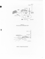
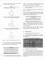
1. INTRODUCTION
(Refer to Figure 1.)
.2.
PREINSTALLA TION INSTRUCTIONS
2.1
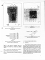
1.1 Motorola HF-SSB Automatic Antenna Tuners,
Models T1961A and TI962A, are antenna matching networks rated at 125 watts peak-envelope-power
(PEP). Model T1961A Antenna Tuner matches the impedance of an end-fed antenna (vertical whip or random
length wire) into a nominal 50-ohm impedance source
with a frequency range from 2-to-18 MHz. Model
T1962A Antenna Tuner performs the same impedance
match, but it can be used only with a 23' whip antenna
and at a frequency range from 2-to-9 MHz.
1.2 AutomatiC tuning is accomplished
through
microprocessor control of reed relays that switch
inductors and capacitors in and out of the matching network. The balance of this installation procedure
describes preinstallation instructions, installation instructions and ground systems for the radio and the
antenna tuner.
TUNE POWER ADJUSTMENT
....
,
"7
CAUTION
The following adjustments
to the
TRITON 20 or TRITON 12 and 24 channel radios must be performed before making electrical connections to the antenna
tuner.
2.1.1
TRITON 20 Adjustment
Step 1. In the TRITON 20 instruction manual
(68P81044E20), refer to the TRN4038A Power
Amplifier circuit board overlay and schematic.
Step 2. With the radio in the TUNE MODE, adjust
potentiometer R441 for 3 watts :t 1 watt of power output into a 50-ohm resistive load.'
2.1.2
TRITON 12 and 24 Channel Adjustment
Step 1. In the TRITON 12 and 24 channel radio instruction manuals (68P81O30E35 and 68P81O34EO5),
refer to the TLN1752A Power Amplifier circuit board
overlay and schematic diagram.
FAEPS-3000S-0
"5381
Figure 1. AutomaticAntenna
@ Motorola, Inc. 1979
All Rights Reserved
Printed in U.S.A.
Tuner
Step 2. With the radio in the TUNE MODE, adjust
potentiometer R41 for 3 watts :t 1 watt of power output
into a 50-ohm resistive load.
It@@jfn(fi)fi@@11
Wff fiU:Ji(fi)~
g@{f\VJfi~
1301 E.Algonquin Road, Schaumburg, II.60196
68P81110E64-0
5/15/SD-PHI
2.2
""8
RADIO MODIFICATIONS
100
2.2.1
The TRITON 20 and TRITON 12 and 24 channel radios require circuitry modification if (hey
were built before July 1, 1980. Those radios built after
this date do not require the following modifications. All
the components required for these modifications are in
a small package of parts supplied with the antenna
tuner. Since components for both radios are included,
some components are not used, depending upon which
radio is modified.
2.2.2
CR110
J3-1O
PA DISABLE
9T
CR12
8.0V
CR21
TD ROt
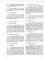
Figure3.
TRITON 20 Schematic DiagramModijications
TRITON 20 Modifications
(Refer to Table 1, and Figures 2 and 3.)
2.2.3 TRITON 12 and 24 Channel Radio
Modifications
The TRITON 20 modification consists of the addition of 2 components to a circuit board.
Step 1. In the TRITON 20 instruction manual, locate
the TRN4032A "A" circuit board overlay and
schematic diagram.
Step 2. Select the components listed in Table 1, and
install the diode and resistor as illustrated in Figure 2.
Table 1. TRITON 20 M odijication Parts List
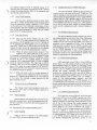
(Refer to Table 2 and to Figures 4 thru 7.)
The TRITON 12 and 24 channel radio modifications consist of changes made on two separate circuit
boards. The first modification is done to the main circuit board by addition of components listed in Table 2.
Figures 4 anCb.Sillustrate where these components are installed. The- second modification is done to the
transmit/receive switch circuit board by the addition of
components listed in Table 2. Figures 6 and 7 illustrate
where these components are installed.
CAUTION
Early versions of 12 and 24 channel
TRITON radios must have resistor R44
on TLN17S2A Power Amplifier changed
to a 3.3k ohm, SOJo,1/4 watt resistor for
proper antenna tuner operation.
CA110
CA12
Step 1. In the TRITON 12 and 24 channel radio instruction manuals, locate the TUAlllOA or TUA1120A
Universal Radio Chassis and Main Board "M" overlay
and schematic diagram.
Step 2. Select the components (CRSI9 thru CR523
and RSI8) listed in Table 2, and install the diodes and
resistor as illustrated in Figure 4. Use sleeving on the
component leads.
CA19
A198
Table 2. TRITON 12 and 24 Channel Radio
Modijication Parts List
a16
""'-30007-0
IC><OI
Figure2.
TRITON 20 CircuitBoard Modifications
2
J
P/O
TRN6227A
TRN6429A
TRN6430A
as
09
.- ..'0"" .
RIS
R24
CR9
""'-30011-0
..r.<o,
RSla
P/O TRNS229A
TRNS867A
TRNS66SA
F
:JOCOO-O
'.SAOI
Figure6.
TRITON 12and 24 ChannelSmall CircuitBoard
Modifications
Figure4.
TRITON 12and 24 ChannelMain Circuit Board
Modifications
'.J
CR4
024
11
.) (PO.DI:5A8LE1 ""9
-;;0
(PO<'_BlT'(T
Q9
M9642
CRS19
CATHODE OF CR41'
«RANGE
11
CATHODE OF CR41T
,(RAHGE
Z)
CATHOOE
((RANGE
31
CRT
"""20
BEPS->OOIO-O
"""21
PIO IIAHOSWITCHIHG
CIRCUITRY SECTION ON
AWN BOORD""
1
OF C114t.
CIISn
CATIiOOE OF Cll419
Figure 7.
TRITON 12 and 24 Channel Small Circuit Board
Schematic Diagram Modifications
«(RANGE 41
""SD
CATItODE
OF C114ZO ,(lUNGE
5)
-100
1tS1.
CATHOD£ OF VR42S
.d!'OD':5AOLE)
G£PS-3000.-o
Figure 5.
TRITON 12 and 24 Channel Main Circuit Board
Schematic Diagram Modifications
Step 3. In the instruction
manual,
locate the
TRN6227A; TRN6429A, or TRN6430A Transmit!
Receive Switch circuit board overlay and schematic
diagram.
I
v
.
Step 4. Remove resistor R24 (220 ohm) from the circuit board and lay it aside. It will not be used.
Step 5. Select the components (CR9 and R24) listed in
Table 2, and install the diode and resistor as illustrated
in Figure 6.
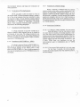
3. INSTALLATION INSTRUCTIONS
3.1
GENERAL
The procedure for a good installation is essentially
the same for either the Model Tl961A or Model T1962A
Antenna Tuner. If the Model T1961A Antenna Tuner is
employed, antennas of the end-fed variety of a 23-foot
whip or up to a 6O-foot long wire may be used with a
frequency range from 2 to 18 MHz. If the Model
T1962A Antenna Tuner is employed, its use is limited to
a 23-foot whip antenna with a frequency range from 2
to 9 MHz. The antenna should be installed as close as
possible or within a maximum of 3 feet of the tuner. The
ground system should be as close as possible or within a
maximum of 5 feet of the tuner.
3
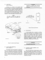
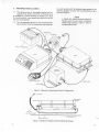
3.2 LOCATION
(Refer to Figure8.)
CAUTION
Regardless of antenna tuner mounting
position, the selected drain hole must face
downward.
Selection of a location for the antenna tuner
should be such that it is as close to the antenna as possible. Long "lead-in" wires greatly increase the possibility of creating radio frequency interference (RFI) with
other electronic equipment on the vessel. There are two
factory installed angle brackets attached to the bottom
of the antenna tuner for mounting purposes. Several
holes and slots are provided on each bracket. It is not
necessary to remove the brackets to mount the tuner.
NOTE
The dealer or installer must supply the
necessary stainless steel mounting hardware.
ANTENNA
TUNER
7
?
DRAIN SCREWS
GAEPS-30013-0
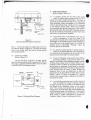
Figure 9. Mounting Positions
3.4
GAEPS-30012-D
A good ground system is required for efficient
antenna tuner operation. Use the ground lug on the
antenna tuner for ground strap attachment. Ground
returns for the electrical circuits may be provided
through the deck or hull of the vessel if these are
metallic; otherwise, a copper strap four inches wide
should be installed from bow to stern. For more detailed
information
regarding grounding,
refer to. the
GROUND SYSTEMS section of this manual.
WARNING
Do not install the antenna tuner without
an adequate ground system.
Figure 8. Antenna Tuner Housing
3.3
DRAIN SCREW REMOVAL
(Refer to Figure 9.)
The antenna tuner has provisions for selection of
one of two drain screws for removal of condensation.
One screw is positioned on the bottom of the housing,
and the other is on the end of the housing. Proper orientation of the drain hole is essential for normal tuner
operation. Remove and discard one screw from the surface that will be at the lowest position when the tuner is
mounted.
4
GROUNDING
3.5
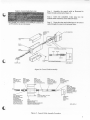
CONTROL CABLE ASSEMBLY AND
INSTALLATION
The control cable must be field assembled. Table 3
lists the items required for assembly of the cable. Of
those parts listed, the connector kit and solder lugs are
supplied with the antenna tuner, but the 3-conductor
cable must be supplied by the dealer or the installer. The
following steps outline the control cable assembly and
installation procedure.
--
Table 3. Control Cable Parts List
Step 1. Assemble the control cable as illustrated in
Figure 10and as directed in Figure 11.
(;
Step 2. Insert the completed I5-pin plug into the
antenna tuner connector of the TRITON radio.
.
For a detailed parts breakdown of the TRN4423A
see PEPS-30lOS. at the rear of this manual.
Connector
Step 3. Route the other end (solder lugs) of the control
cable through the vessel to the antenna tuner.
Kit,
3-GONDUCTOR
CONTROL
CABLE
IS-PIN
CONNECTOR
MAIN
BRACKET
CABLE
RETAINER
WIRE
~
I
I-~/I
()
',~
,.
(31
SOLDER LUGS
EYELET
'~~
-J
.LREW
10F'
1 OF 3 CONNECTIONS
SHOWN
GBEPS-30047-0
Figure 10. Control Cable Assembly
STEP 1:
STRIP INSULATION
11<
SOLDER LUG
TO EACH CONTROL
WIRE.
~
STEP 2:
FEED CONTROL
CABLE THROUGH
HOLE IN MAIN
BRACKET.
STEP 3:
STRJP In" OFF
OUTER JACKET.
STRIP INSULATION
BACK II'" ON EACH WIRE.
STEP .:
ATTACH EACH
CONTROL WI RIOTO
CHOKE-PIN ASSEMBLY
THROUGH AN EYELET
AND SOLDER.
~
,
BRACKET SOTIE-WRAP
IS FLUSH WITH
BRACKET OPENING.
ATTACH STRAIN RELIEF
OVER TIE-WRAP AND
SNAP CABLE 11<
STRAIN
RELIEF INTO BRACKET.
~;::~EACH
---
~
STEP B:
PULL CONTROL CABLE
BACK INTO MAIN
STEP S:
SLI DE HEAT
SHRINKABLE TUBING
OVER ASSEMBLY
11<
SHRINK.
P
'
STEP 7:
ATTACHTJE-WRAP
1/B'" FROM
OUTER JACKET EDGE.
STEP 9:
LOCK SIDE BRACKETS TO
CONNECTOR TABS
AND INSERT SCREWS SECURING SIDE
BRACKETS TO MAIN BRACKET.
Q
CONTROL WIRE WITH
CHOKE-PIN ASSEMBLY
INTO ANTENNA TUNE
CONNECTOR. REFER TO
FIGURE.
FOR CORRECT
CONNECTIONS.
CONNECTOR
MATING
SERRATIONS
DOWN
GBEPS-30070-0
,;
Figure 11. Control Cable Assembly Procedure
5
,.
4.
GROUND SYSTEMS
(Refer to Figures 14 and 15.)
4.1
R.F.
COAX
A common ground for the entire radio system
(radio, dc power supply, antenna tuner, etc.) is required for proper system performance. This type of
grounding is accomplished through the use of three inch
wide grounding straps terminating at the GROUND
LUG on the antenna tuner, which in turn is connected
to the antenna ground plane. When at all possible,
avoid multiple path ground connections. They result in
ground loops which may have high circulating currents.
On certain operating frequencies, ground loops cause
radio and/ or antenna tuner instability.
-~
MOUNTING~
SCREW
GAEPS-30071-O
.
4.2
The ground strap to the antenna tuner must be
within a maximum of 5 feet of the tuner. If the
ground strap is long in terms of the operating frequency
wavelen'6th, it can actually present a high impedance to
the ground lug on the antenna tuner. As a result, the
antenna tuner is electrically "floating" above the
reference ground of the system.
Figure12.
Electrical and Mechanical
Connections
Step 4. Route and connect the solder lugs of the control cable as shown in Figure 12. Tie-wrap the control
cable to the coaxial cable, and attach the lug housing
with mounting screw.
3.6
4.3
An adequate system ground is usually easily obtained on a metal hulled ship with a metal deck.
All communications equipment can be grounded to the
,metal structure of the ship at convenient places.
COAXIAL CABLE
(Refer to Figure 13.)
4.4
Use type RG-58/U or RG-8/U, 50-ohm, coaxial
cable with the appropriate UHF connectors (PL-259) on
both ends to interface the RF OUTPUT from the radio
to the RF INPUT to the antenna tuner.
C~J':""
3 CONOUC1aI
~/
,13(')
CONtRO<.
CASU:
\
ro!MlNAl.S
ANT T1JNE
~
,w...
TRITON HF-SS8
RADIO
'-AHTEHNA
CIN€
I
.rl
~
OR RGlIV COAX
.
4.5
T\JNER
_F
INPUT
\
.
Tl961AOR
TlKZA
ANTENNA
He
Wood and fiberglass vessels present more difficult
grounding problems. Large ground straps are required to electrically bond equipment together, and an
artificial ground plane must be created. Either of two
methods is used to achieve the required ground plane:
ground plates or screening. Ground plates or screening
is installed inside the hull of the craft so that good electrical contact with the' water is made through the
capacitive effect of the hull (dielectric). At least 100
square feet of the area below the water line is recommended. Figure 14 shows an example of a ground
system where a ground plate is placed on the inside of
the hull of the vessel.
.
'--GOlD
BEPS-3OO1'-0
Figure 13. Electrical Block Diagram
WG
GOlD
STRAP
An artificial ground plane can be further improved
with the addition of copper screening connected
through a ground strap to the base of the antenna tuner
and placed in the immediate vicinity of the antenna
tuner. The antenna tuner should also be grounded to
copper pipes, the metal water tank, and the engine to extend the ground system. The addition of 1/4 wavelength
radials extending from the ground lug of the antenna
tuner creates a further improvement in system performance. Figure 15 shows a radial ground system.
.
J
6
!
.
ANTENNA
COPl'ER
SCREEN
ANTENNA TUNER
BULKHEAD
FEED- THRU
INSULATOR
"
\)
METAL
WATER
TANK
~}
GROUND PLATE
GBEPS-30016--D
7
'7
Figure 14.
Ground System on Fiberglass Vessel
~
~~"'-l
1/4 WAVE RADIALS AT
FREQUENCIES OF OPERATION
LEAD-IN
WIRE
GAEPS-30017
-0
Figure 15. Radial Ground System
7
J~
'!.
A=c==
.
.
2
1;00--1--~--'
I f
5 5
i
~'<-4
3
~
:,
-
L
1
j
-
a
~m
~'
-
ft Q"
12
7
GBEPS-:JO103-0
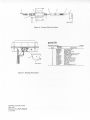
Figure 16. Control Cable Parts Detail
;?
parts I I$t
TRN4423A Connector
CODE
......
"--\
~~J.
15~"QJ
GAEPS-30104-Q
Figure 17. Housing Parts Detail
TRN4423A Connector Kit
Parts List
Motorola No. PEPS-30105-0
51151SG-PHI
1
2
3
4
5
6
7
8
9
10
11
12
13
14
15
PL.6953-O
Kit
MOTOROLA
PART NO.
29-83883C08
42-82018H02
7-82232L01
7-82233L01
3-115613
4-135651
42.10217A02
5.820SOH04
24-83397L01
37.132049
29-841SOL02
14-82834H02
42.10283A20
14-844951.101
3.139102
DESCRIPTlON
LUG, solder; 3 used
STRAIN RELIEF
BRACKET, side; 2 used
BRACKET, main
SCREW,machine; 4-40x 1/4"; 4 used
LOCKWASHER, /Ij)split; 4 used
TIE.WRAP; 2 used
EYELET; 3 used
CHOKE, RF, 30 uH; 3 used
TUBING, clear 1/4"; 3 used
TERMINAL, plug; 3 used
INSULATOR, plug; 15 pin
CLIP, cable
INSULATOR
SCREW, tapping; 8-18 x 1/2"
@
/'~
$
MOTOROLA
Communications
Group
INC.
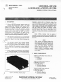
MOTOROLA HF -SSB
AUTOMATIC ANTENNA TUNER
MODELS T1959A, T1961A, T1962A
1.
DESCRIPTION
1.1
Motorola HF-SSB automatic antenna tuners are
antenna matching networks rated at 125 watts
peak-envelope-power. Selection of the network components for antenna matching is performed by a
microprocessor-based circuit that monitors antenna
conditions each time a channel is changed. The entire
tuning process usually takes less than one second.
Microprocessor control eliminates the need for programming, preset adjustments, manual tuning, or
manual adjustments during installation or operation.
1.2
The automatic antenna tuner can accommodate
any number of channels automatically. .New channels can be added at any time without adjusting the
\
)
.. :
impedance source with a frequency range from
2-18 MHz. Model T1961A includes the TRN4423A connector kit for field assembly of the necessary control
cables. Model T1959A uses factory assembled accessory
cables, TKN8123A, TKN8120A and TKN812IA. Otherwise, the T1959A and TI961A are identical. T1959A
and TI961A Antenna Tuners are compatible with the
102-inch niobile whip antenna (TAAI OOOA) from
2-18 MHz if a TKN8119A antenna matching harness is
used.
Model T1962A Antenna Tuner is capable of
matching a 23-foot whip antenna from 2-9 MHz. This
model also includes the field assembled TRN4423A connector kit.
NOTE
Older versions of Motorola single sideband radios must be modified before they
can be used with these tuners. Please refer
to the installation manual for the specific
tuner for more details. Installation
manual 68P81111EI6 applies for tuner
Model T1959A. Installation
manual
68P8111OE64 applies for Models T1961A
and T1962A.
tuner.
1.3 The automatic antenna tuner includes stainless
steel hardware and a weather resistant housing
that insure corrosion resistance and durability. Installation is simplified; the automatic tuning capability
eliminates the need to open the tuner housing during installation.
1.4
Models TI959A and TI961A match the impedance
of an end-fed antenna (23-35 foot vertical whip or
23-60 foot random length wire) into a nominal 50-ohm
2. MODEL COMPLEMENTS
..
.
.. .
.
T1959A 2-18 MHz Base Tuner consists of:
TLAl1O2A
THN6410A
TLA6102A
T1961A 2-18 MHz Tuner consists of;
TRN4423A Connector
TLA II 02A Tuner
THN641OA Housing
TLA61O2ARF Board
T1962A2-9 MHz Tuner consistsof;
.
FAEPS-3000S-0
"5381
)
--~
.
Figure 1. Automatic Antenna Tuner
@ Motorola, Inc. 1981
All Rights Reserved
Printed in U.S.A.
TRN4423A Connector
..
TLA1112ATuner
THN64lOA Housing
TLA6112A RF Board
~h1(f1)fi@@IIlY!JJ(fnltJi(fl)~
ff@ff\VIfi~
1301 E.Algonquin Road, Schaumburg, II.60196
68P81045E90-A
10/1/81.
NWP
3.
PRE-OPERATIONAL CHECK
3.1
The antenna tuner is thoroughly checked and inspected at the factory. However, if the tuner is to
be installed in a remote location or stocked on a shelf
for several months, a pre-operational check on a service
bench is recommended.
3.2
the radio system (with the antenna being replaced by an
antenna simulator circuit). The recommended set-up is
shown in Figure 2.
NOTE
A TKN8119A Mobile Antenna Matching
Harness must be used when checking a
mobile whip antenna. Figure 3 shows a
recommended set-up.
The recommended set-up for the pre-operational
check consists of all the components that comprise
TUNER
Figure 2. Typical Pre-Operational Check Configuration
TUNER GROUND
TERMINAL
MOUNTING
RAIL
EYELEl
7
,;,
I
GAEPS-31085-0
MOUNTING SURFACE
j
I
Figure 3. TKN8119A Mobile Antenna Matching Harness
2
A
3.3
-"~
Circuits for construction of the antenna simulator
are shown in Figures 4 through 6.
NOTE
Figures 4 and 5 apply only for 23 to 60
foot antennas, whip or long wire.
}
mode) of 3 :t 1 watts into a 50-ohm load. Refer to the
radio instruction manual for the procedure for adjusting the radio power level in the tune mode.
3.6
Check the tuner operation by following the procedure given below.
Step 1. Set up the components of the radio installation
as shown in Figure 2.
P
l
OHMS
900
=
.EPS'
..UH
Siep 2. Select Channell and turn the radio on. During
the initial 1 to 2 seconds, the wattmeter should indicate
a power level of approximately 3 watts. The radio
should then return to the receive mode.
3'000-0
Figure 4. Antenna Simulator Circuit for Models
TI959A, T1961A, T1962A (2-10.8 MHz)
CAUTION
Step 3 should only be performed with an
antenna simulator rated for full transmit
power or with a properly installed antenna.
"':r
1 ssp,
2 OHMS
OP'
,.
3.'UH
'EPS.31038.0
Figure 5. Antenna Simulator Circuitfor Models
T1959A and T1961A (10.8-18 MHz)
-"\
Step 3. Whistle into the microphone. Check the wattmeter for forward and reverse power levels. The forward power level should be more than three times the
reverse power level. .
Step 4. Repeat Steps 2 and 3 for each of the other
radio. channels. Insure that the .proper antenna
simulator is used for each channel frequency.
.
"1
-.-7/
1
4. MAINTENANCE
32.'
4.1
2 OHMS
0.5U'
~
100
OHMS
RECOMMENDED TEST EQUIPMENT
The test equipment listed in Table I is recommended for maintaining and troubleshooting the automatic
antenna tuner.
Table 1. Recommended Test Equipment
AE.5-3103&-.
Figure 6. Mobile Whip Antenna Simulator Circuit
, 3.4
Select and construct the antenna simulator circuit
that corresponds to the antenna tuner model being
checked and the operating range of the radio.
CAUTION
These antenna simulator circuits are only
recommended for system tests in the tuneup mode. Tests in other modes should only be made if the simulator circuits are
constructed with parts that are rated to
handle maximum transmitter power.
'\
-_J 3.5 To insure proper operation of the tuner, the radio
must be adjusted for a power level (in the tune
A
4.2
PREVENTIVE MAINTENANCE
4.2.1
Check all external surfaces of the equipment to
see that they are clean. Inspect all connecting
cables and wires for damage or loose connections. It is
especially important that the ground and antenna wires
make good connections at the tuner. Carefully check the
antenna and verify that it is properly insulated from any
metal objects.
.
3
4.2.2
If the equipment surfaces are dirty, wash the external surfaces with mild soap and water using a
clean cloth. Be careful not to allow the electronic components or connectors to get wet.
4.2.3
Preventive maintenance should be scheduled
regularly, i.e. monthly, quarterly, annually. The
interval of maintenance depends on equipment usage
and environment.
4.3
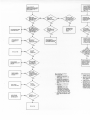
TROUBLESHOOTING
Check for proper operation of the tuner by performing the procedure listed under the Pre-Operational
Check paragraph of this manual. If the tuner is not
operating properly, use the notes on the schematic
diagram and the attached troubleshooting chart to
localize the defective component.
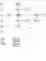
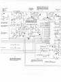
5. THEORY OF OPERATION
5.1
CIRCUIT FUNCTION
A fixed length antenna presents greatly varying
impedances when operating over a wide frequency
range. The tuner must enable the ant.enna to resonate by
compensating for the capacitive or inductive reactance
present. It must also match the resistive component of
the antenna to present a 50-ohm load to the radio output. This antenna tuner is designed to perform both of
these functions automatically in less than 2.5 seconds
without making any preliminary adjustments or settings.
There are five steps of switchable input
capacitance arranged in a binary order, that is,..
the value of a switchable capacitance is half the value of
the next largest switchable capacitance. The values of
switch able input capacitance are 2000, 1000, 500, 250,
and 120 picofarads. The values of switchable output
capacitance for Models T1961A and T1959A are 400,
200, 100, 50, and 27 picofarads. The values of switchable output capacitance for Model TI962A are 50 and
100 picofarads.
5.3.1.3
There are ten steps of switch able inductance
arranged in binary order. The values of switchable inductance are: .08, .15, .29, .55, 1.05, 1.99, 3.8,
7.24, 13.78, and 26.25 microhenries.
5.3.2 Phase Detector
-y
The phase detector circuit consists primarily of
TI, Ul, U2, U3, and U6D. This circuit compares the
phase of the rf voltage to the phase of the rf current and
generates either a logic high or logic low at U6-14. When
the antenna and the tuner represent an inductive load to
the rf output of the radio, the rf current lags the rf
voltage, resulting in a logic high (5 V) at U6-14. When
the antenna and tuner represent a capacitive load to the
rf output of the radio, the rf current leads the rf voltage,
resulting in a logic low (0 V) at U6-14.
5.3.3
VSWR Detector
Two different circuit configurations are used to
tune the antenna. To match antennas with capacitve
reactance, a pi configuration is used. The pi configuration consists of parallel capacitance, followed by series
inductance, followed by parallel capacitance. To match
antennas with inductive reactance, an L configuration is
used. The L configuration consists of series inductance
followed by parallel capacitance.
5.3
5.3.4
CIRCUIT CONFIGURATIONS
CIRCUIT DESCRIPTIONS
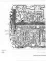
5.3.1 Tuning Elements
5.3.1.1
The tuning elements of the antenna tuner consist of inductive and capacitive components
that are switched into the rf circuit by a series of reed
relays. The tuning elements are selected by the tuner
microcomputer, which enables the transistor driver circuits that activate the relays. The tuning element network consists of parallel capacitance, followed by series
inductance, followed by parallel capacitance. In addition, there is an output inductance of 26.25 microhenries that can be selected by the microcomputer and a
4
.J
5.3.1.2
The VSWR detector consists primarily of T2 and
U6C. A voltage proportional to the forward power of
the transmitter output is developed at U6-1O. A voltage
proportional to the reverse power of the transmitter output is developed at U6-11. If both U5B and U5C are not
activated by the microcomputer, U6-13 drops from
5 volts to 0 volts when a VSWR of 4: 1 is achieved. If
U5B is activated, the 5 to 0 volt transition takes place
when a VSWR of 2: 1 is acheived. If U5C is activated,
the 5 to 0 volt transition takes place when a VSWR of
1.5: 1 is acheived.
5.2
"
fixed output capacitance of 50 picofarads.
Channel Change Circuit
The channel change circuit consists primarily of
transistors Q28-Q33 and inverter U7C. When a radio
channel change takes place, the channel change circuit
applies a negative going, 0.5 second pulse to the
POWER ACK and TUNED INPUT ports of the microcomputer. This pulse prohibits the microcomputer from
beginning a tuning sequence until radio channel selection is complete. One-half second after the channel
change is complete, there is a transition from 5 volts to
0 volts at U7-6. The transition enables the microcom-~.
puter to begin its tuning' sequence. The channel change'
circuit responds only to channel selections made with
A
the channel selection knob. If channel change is initiated by the A/B button, the tune line circuit is used to
<'1
the tuning sequence. Refer to the paragraph that
} initiate
describesthe
tune line circuit.
.'
5.3.5 Tune Power Detector
The tune power detector consists of U5A, U6A,
and U6B. A voltage proportional to the forward power
from the transmitter output is applied to U6-5. When
the forward power level is between 1 and 6 watts, U5A is
activated and a logic low is applied to the POWER ACK
port of the microcomputer to verify that the proper
power level for tuning is present.
...
5.3.6
Tune Line Circuit
5.3.6.1
The tune line circuit consists of U5F, U5G,
U7E, U7F, and a portion of U9. During a tuning sequence, U8-33 applies a low to U7-14. The high at
U7-15 activates U5G which applies a low to the antenna
tune (ANT TUNE) line. A low on the ANT TUNE line
enables the radio to key the transmitter on the selected
channel at a low power level (approximately 3 watts).
5.3.6.2 When the radio is in the receive mode, 3.3 V is
applied to the ANT TUNE line by the radio if
a B channel is being received. If an A channel is being
received, 12 V is applied to the ANT TUNE line. U5F is
activated by the 12 volts applied during A channel
reception; U5F is deactivated when 3.3 volts is applied
during B channel reception. The logic high at U8-33
produces a low at U7-12 that enables the transmission
gate in U9 to apply the output voltage ofU5F to U8-31.
The output of U5F is 0 V when an A channel is selected,
5 V when a B channel is selected.
~.,-,)
5.3.6.3
When the tuner is not in a tuning sequence, a
transition in the voltage level at U8-31 is an indication of a channel change from an A to a B channel
or vice versa. This initiates a tuning sequence for the
newly selected channel.
5.3.7
Voltage Control and Regulation
The voltage control and regulation circuit consists of Q23, Q24, and U4. Final voltage regulation is
provided by U4.
5.3.8
Microcomputer
Microcomputer U8 controls the operation of the
.
automatic antenna tuner. All of the programs that control tuner operation are stored in the microcomputer onboard memory.
5.4
-
)
-,.:7
5.4.1
SEQUENCE OF TUNER OPERATION
Power Applied
When dc power is applied to the SWITCHED
A + line (GRN), the microcomputer is reset.
5.4.2
Initialization and 4: 1 VSWR Detection
The microcomputer applies a low to U8-33 to
produce an 0.4 volt signal at the ANT TUNE line. The
radio is enabled in the tune mode and generates an onchannel signal at approximately 3 watts. If the VSWR is
greater than 4: 1, U6C applies a high to U8-39 and the
microcomputer begins the 4: 1 VSWR tuning sequence.
If the VSWR is less than or equal to 4: 1, U6C applies a
low to U8-39 and the tuner retains the tuning elements
in the current configuration until a channel change occurs.
5.4.3
4: 1 VSWR Tuning Sequence
The microcomputer begins a sequence of switching tuning elements in and out of the rf line. During the
tuning sequence, the microcomputer monitors the
voltage level at U8-1 and U8-39. When a 4:1 match is
achieved, a low is applied to U8-39. A list of tuning
elements '3lsed to achieve the 4: 1 VSWR is stored in the
microcomputer memory, and the microcomputer begins
the 2: 1 VSWR sequence. If a 4: 1 VSWR cannot be
achieved, the tuner reverts to the tuning configuration
previously stored in the microcomputer memory and
begins the termination of tuning sequence.
5.4.4
2:1 VSWR Tuning Sequence
U8-31 goes high to turn U5B on. If the VSWR is
greater than 2: 1, U6C applies a high to U8-39 and the
microcomputer begins a sequence of switching tuning
elements in and out of the rf line. (If the VSWR is less
than 2:1, the 1.5: VSWR tuning sequence is initiated.)
During the tuning sequence, the microcomputer
monitors the voltage level at U8-1 and U8-39. When a
2: 1 match is achieved, U6 applies a low to U8-39. A list
of tuning elements used to achieve the 2:1 VSWR is
stored in the microcomputer
memory, and the
microcomputer begins the 1.5:1 VSWR sequence. If a
2: 1 VSWR cannot be achieved, the tuner reverts to the
tuning configuration previously stored in the microcomputer memory and begins the termination of tuning sequence.
5.4.5
1.5:1 VSWR Tuning Sequence
U8-31 goes low to turn U5B off, and U8-32 goes
high to turn U5C on. If the VSWR is greater than 1.5:1,
U6C applies a high to U8-39 and the microcomputer
begins a sequence of switching tuning elements in and
out of the rf line. During the tuning sequence, the
microcomputer monitors the voltage level at U8-1 and
U8-39. When a 1.5:1 match is achieved, U6 applies a
low to U8-39. A list of tuning elements used to achieve
the 1.5:1 VSWR is stored in the microcomputer
memory, and the microcomputer begins the termination
of tuning sequence. U8-32 goes low to turn U5C off. If
a 1.5:1 VSWR cannot be achieved, the tuner reverts to
the tuning configuration previously stored in the
5
microcomputer memory and begins the termination of
tuning sequence.
5.4.6
Termination of Tuning Sequence
U8-33 goes high to allow the radio to revert to
the receive mode. The microcomputer memory retains a
list of the circuit elements that were switched in when
the sequence ended. Circuits elements remain selected
until there is a voltage transition at ANT TUNE (VIa),
SWITCHED A + (GRN), or CHANNEL CHANGE
(BLU). Tuner operation following these transitions is
described in the following paragraphs.
5.4.7
Transition At Channel Change
When a channel is changed using the channel"-~
selection knob on the radio, a positive going pulse is ap- .
plied to the CHANNEL CHANGE line (BLU). A low is
applied to U8-34 and U8-39 to inhibit tuning until channel selection is complete. One-half second after channel
selection is complete, there is a low to high transition at
U8-34 and U8-39 and a high to low transition at U8-28.
The microcomputer then goes through initialization and
4: 1 VSWR detection.
5.4.10' Tune Power Variations
)
Transition At ANT Tune (VIa)
A voltage transition on the ANT TUNE line indicates a change in radio channel from an A channel to
a B channel, or vice versa. The voltage transition is applied via U5F and U9 to U8-1I. All tuning elements are
switched out and the microcomputer begins initialization and 4: 1 VSWR detection.
5.4.8
5.4.9
Transition At SWITCHED A + (GRN)
If voltage is removed from the SWITCHED A +
line, the list of selected circuit elements stored in the
microcomputer memory is lost. When power is reapplied to the SWITCHED A + line, the microcomputer is
reset and the initialization and 4: 1 VSWR detection process begins.
'I
j
5.4.10.1 If, during a tuning sequence, the tune power
level falls below 1 watt or rises above 6 watts
for more than two seconds, the tuning sequence is stopped. The tuner reverts to the circuit configuration previously stored in the microcomputer memory. This configuration:y> used for antenna matching until there is a
channel change and the tune power is between I and
6 watts. When these two conditions are met the
microcomputer goes to initialization and 4:1 VSWR
detection.
5.4.10.2 If tune power falls outside the 1 to 6 watt range
for less than 2 seconds, the microcomputer
resumes the tuning sequencethat was underway prior to
the level change.
0""""
(,.)'
1
.~
;1
..
6
I
L
dA\N 'O8/Ll/OI
0-9980r-SJ:EI:EI
.oN
(O
D1OJoJoJAl
JJDl{Q iJUpOOl{S3JqnOJ.L
J3Un.L
DUU3JUY:JpDUJOJny
~
~
~
ii
~"
j
j
j
~
"
..
w
"
1
I
~
b
'i
~
~
r
C-\
~
~
...
,.
a
~
ti
~
~
;
:
..c
~
~
~
~
~
L
OIQ'If\I NI .Lln:>..!:)
3Nn.L )I:>3H:>
.
,
t~
11
>
i
L.:.
TUNER DOES NOT
INITIATE TUNING
SEOUENCE WHEN
RADIO CHANNEL
IS CHANGED AND
VSWR > ~:I
TUNER DOES NOT
INITIATE TUNING SEOUENCE
WHEN RADIO IS SWITCHED
ON AND VSWR > ~:1
DISCDNNECT PA
DlSA8LE/CHANNEL
CHANGE CONNECTIO
FROM RADIO
NO
TROUBLESHOOT VSWR
DETECTOR CI RCUIT
CHECK SWITCHED
A+ CIRCUIT IN
RADIO
TROUBLESHOOT
ANT TUNE LINE
CIRCUIT IN
RADIO
YES
GROUND THE PA
DISA8LE/CHANNEL
CHANGE LINE (Bll
CHECK VOLTAGE
AT U8-28, 34, 38
TROU8LESHOOT
TUNE POWER DETECTOR
AND VSWR DETECTOR
NO
f
REPLACE FUSE
YES
TROUBLESHOOT
VOLTAGE REGULATOR
CIRCUITS
NO
CHECK CHANNEL
CHANGE CI RCUIT
IN RADIO
NO
CHECK RESET
CIRCUIT (Q23, Q2~)
TUNER CHANNEL CHA
CIRCUIT IS OPERATIN(
PROPERLY. CHECK
RADIO CHANNEL
CHANGE CI RCUIT.
RELAY AND RELAY DRIVER.
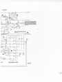
TEST PROCEDUR E
I.
GROUND TPI2 (RUNfTESn.
VERIFY THAT RELAYS K1-K5
ARE CLOSED.
2.
GROUND TPII (ELEMENTS IN/
OUT) AND TP12 (RUNfTEST).
VERIFY THAT RELAYS K6-K21
ARE CLOSED, AND KI-K5 ARE
OPEN.
3.
NO
CHECK EACH
-
DISCONNECTING EITHER
END OF L9.
- APf'L YING 13.8 V TO THE
SWITCHED A+ INPUT (GRN).
- GROUNDING THE APPROPRIATE TEST POINT TO ACTIVATE
RELAY (TPI-TPS,
TP17-TP28).
4.
CHECK TIMING
ELEMENTS: C30,
C3I, C32, AND YI
INDIVIDUALLY
RELAY 8Y:
NO
REPLACE U8
RECONNECT AND SOLDER La. REMOVE GROUNO FROM TPII AND
TPI2.
VSWR DETECTOR TEST P
I.
CONNECT RF OUT TI
ANTENNA OR DUMM
2.
APPLY +5 V TO TP13
SLOW TUNING MODE
AT 2 Hz RATE).
3.
TURN ON RADIO TO
SWITCHED A+ TO TU
~.
MONITOR VOLTAGE
ANDJ8-39.
VOLTAG
SHOULD GRADUAlL
TUNING SEOUENCE
CONDITION IS APPR'
SHOULD 8E lOW fO
1 SECOND DURING 1
TUNER DOES
INITIATE TUNING
SE~UENCE WHEN
RADIO IS TURNED
ON, BUT FULL POWER
VSWR > 4:1
OES NOT
TUNING
:E WHEN
-jANNEL
iED AND
4:1
CTPA
'HANNEL
JNNECTION
10
NOT OK
NO
TROUBLESHOOT
CHANNEL CHANGE
CIRCUIT IN TUNER
REPLACE ANY BAD
RELAY OR DRIVER
NO
YES
THE PA
NOT OK
'CHANNEL
LINE (BLUI
OLTAGE
3,34,38
TROUBLESHOOT
PHASE DETECTOR
CIRCUIT
7
PERFORM VSWR
DETECTO R TEST
PROCEDURE
NO
oEEPS-30866-0
'NELCHANGE
)PERA TING
:HECK
/NEL
'CUlT.
JR TEST PROCEDURE
PHASE DETECTOR TEST PROCEDURE
RF OUT TERMINAL TO
OR DUMMY LOAD.
1.
DISCONNECT ANTENNA
OUT TERMINAL
v TO TP13 TO ENABLE
ING MODE (SWITCHING
;TEl.
2.
(T196OA ANO T1962A MODELS ONLY)
CONNECT A 560 PF CAPACITOR FROM
RF OUT TERMINAL TO GROUND.
RADIO TO APPLY
A+ TO TUNER.
3.
GROUND TP1 1 AND TP12. UNSOlDER
AND REMOVE EITHER END OF R112.
vOLTAGE AT UB-11
!, VOLTAGE AT UB-11
RADUALL Y DROP OURING
'QUENCE AS MATCHED
, IS APPROACHED. U8-39
, LOW FOR APPROXIMATELY
JURING TUNING SEQUENCE.
4.
APPLY 3 WATT RF SIGNAL TO RF INPUT TERMINAL
VARY FREOUENCY OF RF INPUT,
MEASURE VOLTAGE AT UB-I. VOLTAGE SOULD BE LOW WHEN INPUT
FREOUENCY IS BELOW 6.5 MHZ, AND
HIGH WHEN INPUT FREQUENCY IS
ABOVE 7.5 MHz.
5.
6.
FROM RF
RECONNECT AND SOLDER R112. REMOVE GROUND FROM TP11 AND TP12.
TROUBLESHOOT
TUNE POWER DETECTOR
AND VSWR DETECTOR
CH ECK TUN [
CIRCUIT
IN ,
---
.-----
--
------\
\
\
\
\
<
I
"
.
K"
:
UO
/
j
/
"
.,
/
V
\ KI2
(NOTEII
L29
\
\
/
"
~OTE "
\
KI3
INOTEIII
-
\
I
I
I
I
I
I
l
RF
OUTPUT
I
I
NOTES.
I. MOUNTE 0 ON
SOLDER
SIDE
OF BOARD.
I
j
I
)
----:OMPONENT
~
-
SIDE
BOARD DETAIL
--- ---
--
-
-
-
-
J
/
/
/
/
COMPONENT SIDE- BO-EEPS-302'4-0
SOLDER SIDE- BO-EEPS-3025'-0
OL-EEPS-302"-'
;-
---
-
-
--
-
---
- ".-- ---
-.. -. -- -
-.-
--
(
I
/
i
Lr
~,
'1.
RF 'N
SWITCHED
A+
PA D'SABLE/
CHANNEL CHANGE
A NT TUNE
NOT
CONNECTED
j
I
\
\
\
\
\\
..
.~
-
-
U4
--
-
---
-
--
--
---
--
---
lard Detail and
Ust and
'-3lJOO-A
SHOWN FROM COMPONENT
RF BOARD CIRCUIT BOARD
.
-"'-.
PHASE
Rr
INPUT
.J.U.
ov
{
O.ZV
TO
1.0VP'p
T
.I
-*- j\!\!\,
NOTE5
C169
-
.os
I
DETECTOR
WAVEFORM
AT U2.13 HAS SAME PHASE
AS RF
INpUT CURRENT.
OUTPUT
OF U20 IS A SOUARE
0.9V-,-
WAVE.
-+....
R32
1.51<
R97
II<
D
R98
II<
U3 FUP-FLOP
OUTPUTS
USD OUTPUT
IS LOW
I
CAPACITIVE. USD OUTP,
PHASE IS INDUCTIVE.
Rl10
~
.TI<
R99
II<
VOLTAGE
ACROSS
THE REVERSE pOw
VOL TAGE IS APPLIE
RIOO
tl<
RI.
2.2K
.05
WAVEFORM AT UI.SHAS SAME PHASE AS RF .LCISS
.05
INPUTVOLTAGEOUTPUTOFUIDISASOUARE
NOTE 5
- - -
.LC168
1
-
1
~
0.2VTOt.6VP'P:'/\/\/
.05
WAVETHATISAPPUED
TOU3CLOCKINPUT.
-
mm
0.9V-,
-+- - - --
CHANNEL CHANGE CIRCUIT
~IT s
.SV
..
CHA~~E~
PULSE APPLIED BV RADIO WHEN
CHANGED
BYCHANNEL
SELECTOR
'SV
I~~:~~ >BLU
CHANNEL
SWITCH.
029
M9642
IS"
'sv
tR27
'.7K
'.3V-
s.OV-~
RI20
~
10K
030
ING SEOUENCE
DURING CHANNEL
1.001
,sv
CHANGE
Rl"
10K
APpROX,MA
TEL Y 0.5 SEC AFTER
THE FALLING
EDGE OF THE CHANNEL
CHANGE
PULSE
CI82
IS SUFFICIENTL Y DISCHARGED
TO TURN OFF
028.030.
----..
IOK
RI"
0.4 V DURING
""-
3.3 V DURING
12 V DURING
\...l.
ANT TUNE}
vIa
TUNiNG
SEQUENCE
RECEpTION
RECEPTION
OF
OF
B CHANNEL
A CHANNEL
VOLTAGE
10K
JRJ8
_C'7
1.05
AND REGULATION
--
ISO 1 CA'
_C81
S'"
A'
10.2'
~
30
_C16'
1.01
L9
~
30
VR'
,OV
TPI'
.
CR. 1.05
S\A
R12S
'7
R~
IK
TO
~o~~~::s
1.05
L2
=
TO
~UI-I
100 .LCT UI-IS
VRI9
L3
S.IV
1:
.05 TO
U'-I
CI J u,-.s
1.05
LA2 =
TD
~U8-'0
loa
' 7.
""
0.75 At1F'"
nna Tuner
-am
EPS-30253-A
CONTROL
031
M9642
RAS
IGNITION A', "'HT
<NOTUSED>
SWITCHEDA+ ,.GRN
t:-
M9642
DURING CHANNEL
CHANGE
PULSE
O32/S OFF.
033 IS ON. CI82 IS CHARGING;
028-030 ARE
TURNED
ON APpL YING A LOGIC LOW
TO U8-34
AND U/!-39TO 'NHIBIT THE START OF THE TUN.
'5Y
VRIT
S.6V
1..7
=
B
VOLTAGE
ACROSS
CI2
THE FORWARD
POWER
PUT. VOLTAGEISAPPu/
DURING CAP PHASE
U6-9, 3.2 V
U6-&4.'
V
DURmG IND PHASE
U6-9,4.' V
U6-8' 3.2 V
VSWR
DETECTOR
".
c.
8P,
'5V
: .51< I
T
I
CRZ
'.71<
1m
C8
"Z
SW A'
R.
R.
.......
18.
-if-
1
.7P,
REVERSE R6
POWER
101<
LEVEL
.51<IC"'
;
.001
PUTS ARE APPLIED TO U6D.
ow IF RF INPUT PHASE IS
JUTPUT IS HIGH IF RF mpuT
.'"
L7
100
r C.
,.05
-:~~
JD
~
R74
, CR3
TO
U8-'5
AND azz
(VIA R8"
HP,
c.o..L.L
IOOOPF'
:
1
~
101<
'SV
.001
RZ7
'.71<
Q J
..LC49
.001
\J.
C.2.L
IOOOPF'
- --
SW A'
Ki'
~ ~:
-1-~..J
E
~
;D
TO
U8-24
AND 021
(VI< R85'
J
.001
'5V
RI28
'.71<
TO 018
AND all
TO 019
AND alz
..
TO azo
AND 013
use ON TO DETECT '.5"
VSWR
IND.
PHASE..
..
'"
CI20/CZ5
ZI P20
VCc'O
CZ50/C50
Z2 PZI
P2536
2.
PZZ
Z.
PZ'
TO aZ2
CZOOO/CAOO .5
P24
AND 0'5
'.3K
"',
, AND
.8
5.8...10.I1.Z5
XTALI
I Z DBO
TO az----1d
13 OBI
TO a.----b1.
"
TO a.----hi
15 DB'
TO 05-----'=2.
16 DB.
TOO'----6.§.
11 OB5
TO a7--6L
18 OB.
~
XTAUI3
1~Pf'
DBZ
~~I
U8
INT~T
VCC27.2..30
R25
..71<
!.!
. RESET
DET INF'D
ELEMENTS
INIOUT
VSWR
I TO
P 11
P15[3Z
1.511
INPUT 39 T1
AIB
2"
VSHR
CHANNEL INF'D 28 PI I
TUNE 33 P 16
F
GROUNDING TPI1
0 V
4.3 V TO DETECT 1.5"
p"l31
VSWR. 0 VOTHERWISE
G
CHANGE,
KB-K21
VSWR, 0 V OTHERWISE.
AND
TP,2
ENERGIZES
FOR SERVICING.
TUNE LINE
..
.,
CIRCUIT
VRI
3..31<
M
IF AN A CHANNEL IS SELECTED, THE RADIO Ap.
PLIES A + TO THE ANT TUNE LINE. U5F APPLIES
A LOGIC LOW TO U8.3,. IF A B CHANNEL
IS
SELECTED ANT TUNE LINE VOLTAGE IS LOW,
U5F A PPLIES A LOGIC HIGH TOUB.3,.
1.3.5.9
~
-6
WHEN U8-33 GOES
LOW. U7.15 GOES HIGH.
HIGH IS APPLIED TO usa. usa APPLIES A LOW
TO ANT TUNE LINE TliJACTIVA TE RADIO TUNE
MODE.
U7E
K
GROUNDING
TP12 ENERGIZES K,,"5. AND DE.
ENERGIZES KB-K15 AND K21 FOR SERVICING.
1
I
TDF'AST/SLO.
'5V
'5V
5 V
.
L;
C35:"5A5I<HZ'=
VOO Z6 VDD
0.2VTUNED
"ANNEL
NOT
Co
"I
37 PZ'
PDHER ACI< ..
4.3 V TO DETECT2,'
C4Z
'J/O C SHUNT
PZ7
TO al---'d
TO a8-_L8
R23 p
'.7K L
10
TO L4Z
I.05
TO a.----bJ.
0 V
...
'5V
EA.VSS.PI0.PI2.PI3
C500/C'00
R58
0 V WHEN RF' INPUT POWER IS SETWEEN
. WA TTS. 5 V OTHERWISE.
PHASE..
U8-;~-
ANDazo
(VIA R8.
CIOOO/CZOO
G
CAP.
O.BVTOENABLEO'B-OZ.
R73
101<
TO OZ I ANO alA
USA
R.5
.31<
<::).'"
0 V TOENABLE011-075
;;
TO aI 0--1l.!!.
B
RI27
Z71<
H
'8L
H
RZ6
'.71<
C12 IS PROPORTIONAL
TO
WER A T THE TUNER RF IN.
'PLIED VIA R34 TO U6C.
...!:.
TP, U6-36VOLTAGE,
~
7.Z0
POWER DCTECTOR
IFORWARDPOWER
LEVEL
RH
510P'
L
-w.
101<
-c..
..Lc..
'510P'
_ c"' r, - -- 1<2':
~
1 .05'
'0~ -f
\'\..J
-1-
_TP5
OUTPUT OF U6C IS 5 V, UNTIL THE INPUT VSWR
IS THE SAME AS THE VSWR THA T THE TUNER
MICROPROCESSOR
IS TUNING FOR, 4". 2". OR
'.5..1 AS DETERMINED
SY U8-31. U8-32. WHEN
THE APPROPRIA TE VSWR IS ACHIEVED. ua..3IS
0 V.
TUNE
E
c. I
R7
--r
OSS CI1 IS PROPORTIONAL
TO
POWER A 7THE RF TUNER INPUT.
'PLIED VIA L7 TO U6C.
LI
IOO
'.71<
CI
CRI
1.05
c.
CII
J
C5
8PF'
O.B V RELA Y CLOSED
13.B V RELA Y OPEN
c
D
=TZ
...
DURING
TUNING
SEOUENCE.'
IF RF INPUT
DROPS BELOW'
WATT, UB-Z GOES LOW TO
TURN OFF USA, WHICH IN rURN srops
THE
TUNING SEOUENCE. IF RF INPUT RISESASOVE
7 WA TTS. UB-' GOES LOW TO rURN OFF USA.
WHICH
IN
TURN STOPS
THE TUNING
SE.
OUENCE.
SASE VOLTAGE
'.4 V TO CLOSE RELA Y
0 no
OPEN RELA Y
3.2VIFOI.'SOFF
D.' V "ELA Y CLOSED
13.' V "ELA Y OPEN
E
S~ A'
>,
C9Sr-IC9l
2SDPr
i
(SEE SHEET 21
2
(SEE SHEET 21
2S'
- --:1
E
~ ~1<3,'ti
1
~
,
~ -1- ~ ~ - TP.
tP6
I
R62
18'
.P13
vCC.,
or 017
P>S"
'110 C SHU"T
C'2
I.DS
5 . . .9 oI_'--.llill..O<DT
11
TO BASE
TO L.2
1
\l
A LOGIC HIGH AT U8-36 TURNS ON usa. WHICH
IN TURN. TURNS OFF USE AND 016
WHEN USE
IS OFF. 017 IS ON TO ENABLE 018-022.
018-022
DRIVE RELAYS
FOR OUTPUT CAPACITANCE.
A
LOGIC LOW AT U8-36 TURNS OFF U5D. WHICH
IN TURN. TURNS ON 016. 0161S ON TO ENABLE
011.015.
011.015
DRIVE
RELAYS
FOR INPUT
CAPACITANCE.
RU
"'W'<33'
USEO
TALI"
lC3'
12'p,-
nI
;n
c3S;9.S<SKH2=
'AU"
-j
ISP,
C3'
.;~l
12opr
VCC27.29.3'
I"TFT
'SV
,.
WHEN 5 V IS APPUEO TO TP13, "ELAY SWIT.
CHING RA TE IS REDUCED FROM 200 HZ TO 2 HZ
FOR SERVICING.
R21
'Wv22K
TO 'SV
rAST/SLO~
R2S
.. lK
,AST I SLO~
U9
...
lK
ELEMENTS
IN/OUT
1.5:!
VS~
P IS i32
.- TPI3
R.3
lK
TP9
t.S:J
11
12
/
TP10
2: 1
AlB
2: I
V~
"
p,,131
13
'SV
RSI
<7K
TPII
:~~~
-
lcs<
1.05
-
M/1
'sv
) J usr-
_C68
I'oS
10
1.,.5.9
~
UlE
J
<5, AND DE.
-"VICING,
0 V WHEN RADIO SELECTS
5 V WHEN RADIO SELECTS
AN A CHANNEL
A B CHANNEL
EEPS-3D253-A
(SHT ,OFZ)
:\
'J