1
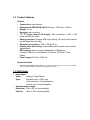
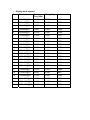
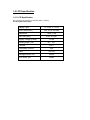
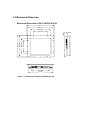
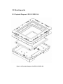
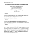
ES-3115 G/R/C/S/V - XA
15" Open-Frame LCD Monitor with
Anti-glare Glass/ Resistive / Capacitive / 3mm SAW /
6 mm Vandal Proof SAW Touchscreens
Copyright Notice
Advantech Co., Ltd copyrights this document. All rights are reserved. Advantech
Co., Ltd. reserves the right to make improvements to the products described in
this manual at any time. Specifications are thus subject to change without notice.
No part of this manual may be reproduced, copied, translated, or transmitted in
any form or by any means without the prior written permission of Advantech Co.,
Ltd. Information provided in this manual is intended to be accurate and reliable.
However, Advantech Co., Ltd. assumes no responsibility for its use, not for any
infringements upon the rights of third parties that may result from its use.
All brand and product names mentioned herein are trademarks or registered
trademarks of their respective holders.
FCC Class A
This equipment has been tested and found to comply with the limits for a Class A
digital device, pursuant to Part 15 of the FCC Rules. These limits are designed to
provide reasonable protection against harmful interference when the equipment
is operated in a commercial environment. This equipment generates, uses and
can radiate radio frequency energy. If not installed and used in accordance with
this user's manual, it may cause harmful interference to radio communications.
Operation of this equipment in a residential area is likely to cause harmful
interference, in which case the user will be required to correct the interference at
his own expense.
1st Edition Printed in Taiwan
April 2004
Packing List
Before installing your equipment, make sure that the following materials have
been received:
•
ES-3115G-XA or ES-3115R-XA or ES-3115C-XA or ES-3115S-XA or
ES-3115V-XA
• Accessory box, including:
- CD for ES-3115G/R/C/S/V-XA Driver
- 12V DC Power adapter
- 2-wire Power cord for adapter
- 1.8 m VGA cable
- 1.8 m RS-232 cable for
If any of these items are missing or damaged, contact your distributor or sales
representative immediately.
Additional Information and Assistance
1. Visit the Advantech web sites at www.advantech.com or
www.advantech.com.tw where you can find the latest information about
the product.
2. Contact your distributor, sales representative, or Advantech's customer
service center for technical support if you need additional assistance.
Please have the following information ready before you call:
• Product name and serial number
• Description of your peripheral attachments
• Description of your software (operating system, version, application
software, etc.)
• A complete description of the problem
• The exact wording of any error messages
Safety Instructions
1.
2.
3.
4.
5.
6.
7.
8.
9.
10.
11.
12.
13.
14.
15.
Read these safety instructions carefully.
Keep this User's Manual for later reference.
Disconnect this equipment from any AC outlet before cleaning. Use a damp
cloth. Do not use liquid or spray detergents for cleaning.
For plug-in equipment, the power outlet socket must be located near the
equipment and must be easily accessible.
Keep this equipment away from humidity.
Put this equipment on a reliable surface during installation. Dropping it or
letting it fall may cause damage.
The openings on the enclosure are for air convection. Protect the equipment
from overheating. DO NOT COVER THE OPENINGS.
Make sure the voltage of the power source is correct before connecting the
equipment to the power outlet.
Position the power cord so that people cannot step on it. Do not place
anything over the power cord.
All cautions and warnings on the equipment should be noted.
If the equipment is not used for a long time, disconnect it from the power
source to avoid damage by transient over voltage.
Never pour any liquid into an opening. This may cause fire or electrical
shock.
Never open the equipment. For safety reasons, the equipment should be
opened only by qualified service personnel.
If one of the following situations arises, get the equipment checked by
service personnel:
a. The power cord or plug is damaged.
b. Liquid has penetrated into the equipment.
c. The equipment has been exposed to moisture.
d. The equipment does not work well, or you cannot get it to work according
to the user's manual.
e. The equipment has been dropped and damaged.
f. The equipment has obvious signs of breakage.
DO NOT LEAVE THIS EQUIPMENT IN AN UNCONTROLLED
ENVIRONMENT WHERE THE STORAGE TEMPERATURE IS BELOW
-20°C (-4°F) OR ABOVE 60°C (140°F). THIS MAY DAMAGE THE
EQUIPMENT.
Contents
Chapter 1 Introduction ................................................... 1
1.1
1.2
1.3
1.4
Introduction...................................................................... 2
Product Features ............................................................. 3
VGA Signal ....................................................................... 4
LCD Specification............................................................ 5
1.4.1 LCD Specification ................................................. 5
1.4.2 LCD Pin Definition ................................................ 6
1.5 Touchscreen Specification ............................................. 7
1.6 External AC Power Adaptor............................................ 8
1.7 Environment..................................................................... 8
Chapter 2 System Setup ................................................ 9
2.1
2.2
2.3
2.4
2.5
2.6
2.7
2.8
2.9
Introduction.................................................................... 10
Preparing for First-time Use ......................................... 10
I/O arrangement ............................................................. 10
Installation Procedure................................................... 11
OSD Control ................................................................... 11
Enable the Capacity Touchscreen (ES-3115C-XM)..... 12
Enable the Resistive Touchscreen (ES-3115R-XM) .... 12
Enable the SAW Touchscreen (ES-3115S-XM)............ 12
Enable the 6mm SAW Touchscreen (ES-3115SV-XM) 13
Chapter 3 Specifications.............................................. 14
3.1 Introduction.................................................................... 15
3.2 Mechanical Dimension.................................................. 16
3.2.1 Mechanical dimension of ES-3115 C/R–XM...... 16
3.2.2 Mechanical dimension of ES-3115 S/SV–XM.... 17
3.3 Cut-out Dimension of ES-3115C/R/S/SV Rear Mounting18
3.4 Mounting Guide ............................................................. 19
3.4.1 Mounting guide of ES-3115 C/R-XM .................. 19
3.4.2 Mounting guide of ES-3115 S/SV-XM ................ 20
3.5 Exploded Diagram ......................................................... 21
3.5.1 Exploded Diagram of ES-3115 C/R-XM ............. 21
3.5.2 Exploded Diagram of ES-3115 S/SV-XM ........... 22
3.6 Electrical Block Diagram .............................................. 23
3.7 ADC Board ..................................................................... 24
3.8 DC to AC Inverter........................................................... 25
3.9 Touchscreen Control Board ......................................... 26
Figures
Figure 2-1:
Figure 3-1:
Figure 3-2:
Figure 3-3:
Figure 3-4:
Figure 3-5:
Figure 3-6:
Figure 3-7:
Figure 3-8:
Figure 3-9:
Figure 3-10:
Figure 3-11:
Figure 3-12:
Figure 3-13:
Rear view of the ES-3115 C/R/S/SV-XM..............................………16
Dimensions of the ES-3115 C/R-XM .............................................. 23
ES-3115 C/R-XM Dimensions of cutoff and panel
mounting holes ..........................................................................…..24
ES-3115 S/SV-XM Dimensions of cutoff and panel
mounting holes ............................................................................... 25
Rear mounting of the ES-3115 C/R-XM ......................................... 26
Rear mounting of the ES-3115 S/SV-XM ....................................... 27
Exploded diagram of the ES-3115 C/R-XM.................................... 28
Exploded diagram of the ES-3115 S/SV-XM.................................. 29
Block Diagram …………………………………………….……………30
Locating connectors on ADC board ................... …..………………31
Locating connectors on DC/AC inverter …………………………..32
Locating connector of ES-3115C control board ………………………33
Locating connector of ES-3115R control board …………………….…33
Locating connector of ES-3115S and ES-3115SV control board……34
CHAPTER
General Information
This chapter includes:
•
Introduction
•
Product Features
1
1.1 Introduction
This product, LCD touch monitor, is mainly focused on Kiosk market or
Human Machine Interface (HMI). It is a core module for Kiosk application.
The LCD touch monitor supports direct VGA analog signal inputs, which
make it more compatible and adaptable to connect to computers widely
used in the current market.
The LCD touch monitor just provides a steel open frame so that Kiosk
providers can design their specific IDs to demonstrate their own Kiosk
application. Comparing with traditional CRT monitor, LCD monitor takes
great advantage on module size and weight; Kiosk providers can therefore
make an easier and more flexible design. LCD monitor can also provide
high brightness and contrast to achieve better viewing effect. Based on
market demand, the size of LCD touch monitor is focused on fifteen inches.
As a Kiosk application product, touch screen is always the best choice as a
human machine interface. SAW and Capacitive and Resistive sensor used
in touchscreen can make applied force lighter and thus use easier. In
addition, the SAW 6mm sensor can also provide impact resistant except the
touch function.
1.2 Product Features
General
•
•
•
•
•
•
•
•
•
•
Construction: steel chassis
Dimensions for G/R/C/S/V (W x H x D): 414 mm x 322.2 mm x 500 mm
Weight: 4.1 kg
Mounting: rear mounting
15" TFT active matrix LCD display: XGA resolution of 1024 x 768
pixels with 262144 colors.
Analogy interface: Accepts RGB input directly. DVI and Audio function
can be supported optionally
Recommend resolution: 1024 x 768 @ 75 Hz.
Display mode Auto tuning: automatically execute when a new mode is
implemented.
OSD controls: allow on-screen adjustments of Brightness,
Contrast, RGB Auto Color Balance, H-Position, V-Position, Clock,
Phase.
Power Supply: DC input 12V/4.0A
Internal functions
•
ADC Core logic chipset: M-Star MST9111; built-in high speed clock recovery circuit and PLL
circuit; supports RGB offset/ RGB gain and gamma correction.
1.3 VGA Signal
•
•
Input signal:
Video:
Analog 0.7Vpp/75ohms
Sync.:
Separate sync. LVDS Level
Horizontal sync. Positive/Negative
Vertical sync. Positive/Negative
Synchronization range:
Horizontal: 30k to 60k Hz (automatically)
Vertical:
56Hz to 75 Hz (automatically)
•
Display mode support:
Item
Resolution
H
Freq.(kHz)
V Freq.(Hz)
Note
1
640x400@70
31.469
70.087
VGA
2
640x480@60
31.469
59.940
VESA
3
640x480@66
35.000
66.667
MAC
4
640x480@72
37.861
72.809
VESA
5
640x480@75
37.500
75.000
VESA
6
720x400@70
31.469
70.087
TEXT
7
800x600@56
35.156
56.250
VESA
8
800x600@60
37.879
60.317
VESA
9
800x600@72
48.077
72.188
VESA
10
800x600@75
46.875
75.000
VESA
11
832x624@75
49.107
75.087
MAC
12
1024x768@60
48.363
60.004
VESA
13
1024x768@70
56.476
70.069
VESA
14
1024x768@75
60.023
75.029
VESA
15
1024x768@75
60.241
75.020
MAC
16
1152x864@70
63.850
70.000
VESA
17
1152x864@75
67.500
75.000
VESA
18
1152x870@75
68.681
74.980
MAC
19
1280x960@60
60.000
60.000
VESA
20
1280x1024@60
63.980
60.000
VESA
21
1280x1024@70
74.882
69.853
VESA
22
1280x1024@75
79.976
75.025
VESA
1.4 LCD Specification
1.4.1 LCD Specification
DF-14H-20P-1.25H (Hirose) or CWY20G-A0D1T (PTWO)
Pin No. Symbol Description
Display Type
15” XGA TFT LCD
Active Area (mm)
304.128 X 228.096
Resolution
Dot Pitch (mm)
Supply Voltage (Panel)
Viewing angle (v,h)
Contrast
Luminance (cd/m2)
1024 X 768
0.297 X 0.297
12 Vdc
80°, 120°
400:1
250
Color
262144
Backlight MTBF (hr)
25000
LCD MTBF (hr)
50000
1.4.2 LCD pin definition
M150XN07 pin definition is shown in the table below.
1
2
3
4
5
6
7
8
9
10
11
12
13
14
15
16
17
18
19
20
VDD
VDD
VSS
VSS
Rin0Rin0+
VSS
Rin1Rin1+
VSS
Rin2Rin2+
VSS
ClkINClkIN+
VSS
Rin3Rin3+
VSS
NC
Power Supply, 3.3V (typical)
Power Supply, 3.3V (typical)
Ground
Ground
- LVDS differential data input (R0-R5, G0)
+ LVDS differential data input (R0-R5, G0)
Ground
- LVDS differential data input (G1-G5, B0-B1)
+ LVDS differential data input (G1-G5, B0-B1)
Ground
- LVDS differential data input (B2-B5, HS, VS, DE)
+ LVDS differential data input (B2-B5, HS, VS, DE)
Ground
- LVDS differential clock input
+ LVDS differential clock input
Ground
NC
NC
Ground
NC Please *floating* and don’t connect to ground.
1.5 Touchscreen Specification
1.5.1 ES-3115C (Capacity)
•
•
•
•
•
•
•
Type: 3M Touch Systems-Microtouch capacity touch screen
Resolution: 1024 x 1024
Light Transmission: 85%
Touch Life Cycle: 225 million
Controller: RS-232 interface
Communication speed: up to 19.2K baud.
Power consumption: +5 V @ 100 mA
1.5.2 ES-3115R (Resistive)
•
•
•
•
•
•
•
Type: EloTouch resistive touch screen
Resolution: Continuous
Light Transmission: 75%
Touch Life Cycle: 35 million
Controller: RS-232 interface
Communication speed: up to 19.2K baud.
Power consumption: +5 V @ 200 mA
1.5.3 ES-3115S (SAW)
•
•
•
•
•
•
•
Type: EloTouch Surface Acoustic Wave (SAW)
Resolution: 4096 x 4096
Light Transmission: 91%
Touch Life Cycle: 50 millions
Controller: RS-232 interface
Communication speed: up to 19.2K baud.
Power consumption: +5 V @ 60 mA
1.5.4 ES-3115SV (6mm SAW)
•
•
•
•
•
•
•
Type: EloTouch Surface Acoustic Wave (6 mm SAW)
Resolution: 4096 x 4096
Light Transmission: 91%
Touch Life Cycle: 50 millions
Controller: RS-232 interface
Communication speed: up to 19.2K baud.
Power consumption: +5 V @ 60 mA
1.6 External AC Power Adapter
• Output: 12Vdc/4.0A
• Input:
100 ~ 240 Vac, 47 ~ 63 Hz, 1.2A
• Efficiency: better than 84% under maximum load.
MTBF: 50,000 hr at 25°C
•
1.7 Environment
0°C ~ 45°C (32° ~112°)
• Relative humidity: 5 ~ 95 % @ 40° (non-condensing)
10G peak acceleration (11 msec duration)
• Shock:
• Certification: FCC class A
• Temperature:
CHAPTER
System Setup
• Introduction
• Preparing for First-time Use
• I/O arrangement
• Installation Procedure
• OSD Control
• Enabling the Touchscreen
2
2.1 Introduction
This chapter describes basic features and procedures for using the
Open-frame LCD monitor. Topics covered include the system installation,
OSD control, Touchscreen, and so on.
2.2 Preparing for First-time Use
Before you start to set up the ES-3115 LCD Monitor, You should have at
least the following items ready in your accessory box:
• 12V DC Power adapter
• 2-wire Power cord for adapter
• 1.8m VGA cable
• 1.8m RS-232 cable (Not available for ES-3115G)
• CD for ES-3115R/C/S/V driver and User’s Menu
2.3 I/O arrangement
The diagram shows the VGA port, RS-232 port and DC Power inlet.
DVI
VGA
COM
MENU
DOWN
PWR.
UP
AUTO TUNE
PWR. LED
Figure 2-1: Rear view of the ES-3115R/C/S/V
DC-IN
2.4 Installation Procedure
The ES-3115 can only be powered by an AC electrical outlet adapter (90 ~
240 volts). Be sure to always handle the power cord and power adapter by
holding the plug ends only.
1. Make sure that the system power is turned off.
2. Connect the VGA cable and RS-232 cable between the ES-3115 and
your PC system.
3. Plug the 2-way power cord to the power adapter. Plug the adapter cable
to the DC 12V jack of ES-3115.
4. Connect the 2-pin male plug of the power cord to an electrical outlet.
5. Turn on the PC system.
2.5 OSD Control
OSD buttons
Adjusting with OSD control
Five different keys are well-defined for operation. They are labeled on the
keypad.
1.
(Power KEY) is designated for Power On/Off
2. [Menu] (Menu KEY) is designated for Menu/Enter function depending
on the selected item. Pressing [Menu] can invoke OSD menu. After that,
[Menu] is also an entry key.
3. [← /↑] (INC KEY) is designated for selection function in up direction in
OSD menu and also to increase the value on selected function.
4. [→ /↓] (DEC KEY) is designated for selection function in down direction
in OSD menu and also to decrease the value on selected function.
5. [Auto Tune] (AUTO KEY) is designated for invoking AUTO ADJUST
function at any time once is pressed for H-position, V-position, Pixel
Clock and Phase for an optimal image.
OSD Screen
Press ”INC” or “DEC” to locate the item you desire to change, then press
“Menu” to make the adjustment, when press “Menu” again to go back to
main menu.
OSD Function List
Automatically adjusts H-position, V-position, Pixel
Clock and Phase for an optimal image
Press “Menu” to execute
Adjust the Brightness
Press “INC” or “DEC” to adjust the parameter
Adjust the difference between the light and dark
areas
Press” INC” or “DEC” to execute
Adjusts the video distortion. It will appear horizontal
noise on the screen while adjust the Clock.
Press” INC” or “DEC” to adjust the parameter
Adjusts the video distortion. It will appear vertical
noise on the screen while adjust the Phase
Press” INC” or “DEC” to adjust the parameter
Move the display picture
Press” INC” to the right, press “DEC” to the left
Move the display picture
Press” INC” to the up, press “DEC” to the down
Adjusts the sharpness (Available in Scaling-up mode)
Press” INC” or “DEC” to adjust the parameter
Zoom ratio change between VGA and Text mode
Press “Menu” to execute
Adjust the OSD transparency
Press” INC” to deepen or “DEC” to shallow
Adjust the OSD position
Press” INC” to the right, press “DEC” to the left
Adjust the OSD position
Press” INC” to the up, press “DEC” to the down
Adjust color temperature
Press” INC” or “DEC” to select a color mode
Adjust color temperature for User mode
Change OSD language
Press” INC” or “DEC” to select, and press “Menu” to
execute
Exit the OSD menu and save the values
Press “Menu” to execute
Restore the default value (The value according to the
factory mode)
Press “Menu” to execute
2.6 Enable the Capacity Touchscreen driver (ES-3115C-XA)
The capacity touchscreen of ES-3115C-XM is patented technology
available from 3M Touch System. Its tough, scratch-resistant and
wear-resistant feature is an ideal choice for unattended kiosks and POI
applications in public places like train stations, airports, malls, supermarket,
and etc.
ES-3115C-XA provides 1 CD kit which contain capacitive driver. It enables
you to use the capacitive touchscreen with applications running in Windows
environments. You can run Windows programs and use touch input without
any program modification.
1. Make sure the RS-232 cable is properly connected.
program cannot configure the touchscreen without it.
The Setup
2. Insert the CD Kit into your PC system's CD drive.
3. Change to the \3M Microtouch\ directory. Click the SETUP.EXE
installation program. The Setup program begins to execute and load the
TouchWare files.
4. Follow the instructions displayed on the screen. Make your selections
carefully when answering questions to complete the installation.
2.7 Enable the Resistive Touchscreen driver (ES-3115R-XA)
The resistive touchscreen of ES-3115R-XA is patented technology available
from Elotouch System. It is an ideal choice for unattended kiosks and POI
applications in public places like train stations, airports, malls, supermarket,
and etc.
ES-3115R-XA provides 1 CD kit which contain resistive driver. It enables
you to use the resistive touchscreen with applications running in Windows
environments. You can run Windows programs and use touch input without
any program modification.
1. Make sure the RS-232 cable is properly connected.
program cannot configure the touchscreen without it.
The Setup
2. Insert the CD Kit into your PC system's CD drive.
3. Change to \EloTouch directory and change to the subdirectory
corresponding to the Windows version you are using now. Click the
SETUP.EXE installation program. The Setup program begins to execute
and load the Elotouch’s driver.
4. Follow the instructions displayed on the screen. Make your selections
carefully when answering questions to complete the installation.
2.8 Enable the SAW Touchscreen driver (ES-3115S-XA)
The SAW touchscreen of ES-3115S-XA is patented technology available
from Elotouch System. Its tough, scratch-resistant and wear-resistant
feature is an ideal choice for unattended kiosks and POI applications in
public places like train stations, airports, malls, supermarket, and etc.
ES-3115V-XA provides 1 CD kit which contain SAW driver. It enables you
to use the resistive touchscreen with applications running in Windows
environments. You can run Windows programs and use touch input without
any program modification.
1. Make sure the RS-232 cable is properly connected.
program cannot configure the touchscreen without it.
The Setup
2. Insert the CD Kit into your PC system's CD drive.
3. Change to \EloTouch directory and change to the subdirectory
corresponding to the Windows version you are using now. Click the
SETUP.EXE installation program. The Setup program begins to execute
and load the Elotouch’s driver.
4. Follow the instructions displayed on the screen. Make your selections
carefully when answering questions to complete the installation.
2.9 Enable the 6mm Touchscreen driver (ES-3115V-XA)
The 6mm touchscreen of ES-3115SV-XA is patented technology available
from Elotouch System. Its tough, scratch-resistant and Impact-resistant
feature is a ideal choice for unattended kiosks and POI applications in
public places like train stations, airports, malls, supermarket, and etc.
ES-3115V-XA provides 1 CD kit which contain capacitive driver. It enables
you to use the resistive touchscreen with applications running in Windows
environments. You can run Windows programs and use touch input without
any program modification.
1. Make sure the RS-232 cable is properly connected.
program cannot configure the touchscreen without it.
The Setup
2. Insert the CD Kit into your PC system's CD drive.
3. Change to \EloTouch directory and change to the subdirectory
corresponding to the Windows version you are using now. Click the
SETUP.EXE installation program. The Setup program begins to execute
and load the Elotouch’s driver.
4. Follow the instructions displayed on the screen. Make your selections
carefully when answering questions to complete the installation.
CHAPTER
3
Specification
• Introduction
• Mechanical Dimension
• Cut-out Dimensions for Rear Mounting
• Mounting Guide
• Exploded Diagram
• Electrical Block Diagram
• ADC Board
• DC to DC Power Board
• DC to AC Inverter
• Touchscreen Control Board
3.1 Introduction
The mechanical design concept of ES-3115 G/ R/C/ S/ V -XA follows easy
assembling, easy maintenance principles. Two main metal parts are used to
support PCB, LCD panel, and touch screen. Basically, front frame and back
frame form a space to contain all parts of LCD touch monitor. The back frame
metal plate are used to mount PCB boards and LCD panel, front metal frame is
used to mount the Touchscreen.
3.2 Mechanical Dimension
Mechanical Dimension of ES-3115G/R/C/S/V-XA
414.00
50.00
286.80
322.20
305.40
220.00
160.50
396.00
300.00
210.50
278.40
377.60
Figure 3-1: Dimensions of the ES-3115G/R/C/S/V–XA
3.3 Cut-out Dimension for ES-3115 G/R/C/S/V-XA Rear Mounting
To construct a suitable panel, refer to the following cutout & elongated holes
dimension diagram.
306.00
Display opening
size
Figure 3-3: ES-3115 G/R/C/S/V–XA dimensions of cut-off.
229.00
SUGGESTED
3.4 Mounting guide
To mount the ES-3115G/R/C/S/V-XA into a panel or kiosk:
1. Build 8 screw studs along the four sides of the cut out opening based on
the dimension given on the drawing above.
2. There are ten elongated holes located along the four sides of the open
frame monitor. Mount the open frame LCD monitor on by aligning the
screw studs with the elongated hole.
3. Tighten the screw stud with hex nut and make sure it is stable.
Note: The screw stud should not be less than M4 and 5mm in height.
Figure 3-4: Rear mounting of the ES-3115 G/R/C/S/V-XA
3.5 Mounting guide
3.5.1 Exploded Diagram of ES-3115 G/R/C-XA
Figure 3-6: Exploded diagram of the ES-3115 G/R/C-XA
3.5.2 Exploded Diagram of ES-3115 S/ V –XA
Figure 3-7: Exploded diagram of the ES-3115S/ V –XA
3.6
Electrical Block Diagram
According to the product idea, 15"” LCD panel and touchscreen are the
basic two components in this product. Besides, in order to reduce the depth
of LCD touch monitor and solve cooling problem at the same time, a DC
input is designed to remove the AC switching power supply. An AC
switching power adapter of full range is used to provide DC voltage of the
monitor.
The LCD touch monitor is constructed based on steel open frame
architecture. It consists of a 15"” LCD panel, an DC to AC inverter board to
support a set of cold cathode fluorescent light (CCFL), an analog to digital
converter board (ADC) to convert analog RGB signals to digital ones, and a
touchscreen used as a pointing device. A metal chassis supports the whole
module.
Block Diagram
RS232
T/S ctrl BD
Touch screen
DC12V
ADC board
VGA
LCD panel
OSD
Inverter
Figure 3-8: Block Diagram
3.7 ADC Board
The ADC board is used to convert RGB signal to LCD digital signal and
send to LCD panel to display. The ADC board is as below:
Figure 3-9:
Locating connectors on ADC board
3.8 DC to AC Inverter
The DC/AC inverter is used to provide the power to LCD backlight. The
inverter is as below:
Figure 3-10:
Locating connectors on DC/AC inverter
3.9 Touch Screen Control Board
Except ES-3115G-XA, all other ES-3115 series provide various touch screen
with different technical. For ES-3115C-XA, it use 3M MicroTouch’s Capacity
Touch Screen sensor and has the control board as below:
Figure 3-11: Locating connector of ES-3115C control board
ES-31153115R-XA used the ELO’s resistive touch screen as below:
Figure 3-12:
Locating connector of ES-3115R control board
ES-3115S-XA and ES-3115V-XA used the ELO’s Surface Wave touch screen as
below:
Figure 3-13:
Locating connector of ES-3115S and ES-3115V control board