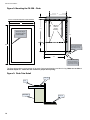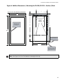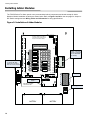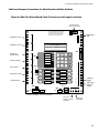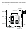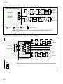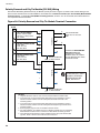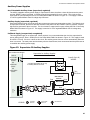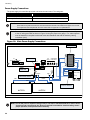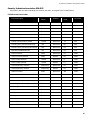
1
Advanced Life Safety Solutions
Advanced Life Safety Solutions
FX-350 SERIES
Analog/Addressable Fire Alarm Panels
Canada
25 Interchange Way
Vaughan, ON L4K 5W3
Tel: 905-660-4655 Fax: 905-660-4113
U.S.A.
60 Industrial Parkway
Cheektowaga, New York 14227
Tel: 1-888-660-4655 Fax: 1-888-660-4113
© Mircom 2006
Printed in Canada
Subject to change without prior notice
www.mircom.com
Installation and Operation Manual
LT-959 Rev. 2
October 2009
FX-350 Series Installation and Operation Manual
Table of Contents
Table of Contents..................................................................................................................... i
List of Figures and Tables....................................................................................................... iii
Industry Canada and FCC Notice ........................................................................................... 1
Introduction .............................................................................................................................. 2
Features................................................................................................................................ 2
Conventions ............................................................................................................................ 3
Circuits ................................................................................................................................. 3
Zone/Group........................................................................................................................... 3
Display Points ...................................................................................................................... 3
Wiring Styles ........................................................................................................................ 3
System Components .............................................................................................................. 4
Panel Models ........................................................................................................................ 4
Output Class A converter: four circuits ................................................................................. 5
Polarity reversal/city tie ......................................................................................................... 5
Remote Annunciator ............................................................................................................. 6
Smart Relay Module ............................................................................................................. 6
RAM-216 Remote Annunciator ............................................................................................. 6
Panel Components and System Accessories ....................................................................... 7
Analog/Addressable Devices ................................................................................................ 8
Mechanical Installation............................................................................................................ 9
Installing the Enclosures ....................................................................................................... 9
Installing Adder Modules ........................................................................................................ 12
Cable and Jumper Connections for Main Board and Adder Modules .................................. 13
OCAC-304 Output Class A Converter Adder Module .......................................................... 15
Polarity Reversal and City Tie Module (Model PR-300) ...................................................... 16
RAX-332 Display Adder Module ........................................................................................... 16
Circuits and Devices................................................................................................................ 17
Addressable/Analog Devices ................................................................................................ 17
Analog Devices ..................................................................................................................... 18
Contact Inputs....................................................................................................................... 18
Contact Outputs ................................................................................................................... 18
Field Wiring .............................................................................................................................. 19
Main Fire Alarm Board Field Wiring ..................................................................................... 19
Loop Isolators ....................................................................................................................... 19
Loop Operation ..................................................................................................................... 20
Indicating (Powered Output) Circuits .................................................................................... 21
Indicating Circuit Wiring ....................................................................................................... 21
Dialer Wiring ......................................................................................................................... 23
Polarity Reversal and City Tie Module (PR-300) Wiring ...................................................... 24
Auxiliary Power Supplies ...................................................................................................... 25
Power Supply Connections................................................................................................... 26
System Checkout .................................................................................................................... 27
Before turning the power “ON” ............................................................................................. 27
Power-up procedure ............................................................................................................ 27
Troubleshooting ...................................................................................................................... 27
Indicators, Controls and Operations ..................................................................................... 28
Common Indicators............................................................................................................... 29
Common Controls ................................................................................................................. 30
Single Stage Operation......................................................................................................... 31
Two-Stage Operation............................................................................................................ 32
Positive Alarm Sequence...................................................................................................... 33
Enabling or Disabling the Positive Alarm Sequence............................................................. 33
Input Types ........................................................................................................................... 34
i
Table of Contents
Output Types........................................................................................................................
Evacuation Codes ................................................................................................................
Remote Annunciator Operation .............................................................................................
Dialer Operation ......................................................................................................................
Appendix A: Compatible Receivers.......................................................................................
Appendix B: Reporting ..........................................................................................................
Ademco Contact-ID .............................................................................................................
Security Industries Association SIA-DCS ............................................................................
Appendix C: Specifications...................................................................................................
Appendix D: Power Supply and Battery Calculations ........................................................
Warranty & Warning Information ..........................................................................................
Warning Please Read Carefully ...........................................................................................
Limited Warranty ..................................................................................................................
Warranty Procedure .............................................................................................................
Disclaimer of Warranties ......................................................................................................
Out of Warranty Repairs ......................................................................................................
ii
36
37
40
41
41
42
42
43
44
45
47
47
49
49
49
50
FX-350 Series Installation and Operation Manual
List of Figures and Tables
Figure 1: Wallbox Dimensions / Mounting the FX-350 - Surface .........................................9
Figure 2: Mounting the FX-350 - Flush ...............................................................................10
Figure 3: Flush Trim Detail ...................................................................................................10
Figure 4: Wallbox Dimensions / Mounting the FX-351/FX-353 – Surface /Flush ................11
Figure 5: Installation of Adder Modules ..............................................................................12
Figure 6: Main Fire Alarm Board Cable Connectors and Jumper Locations ........................13
Figure 6A: Main Board (3 loop model) Cable Connectors and Jumper Locations ...............14
Figure 7: OCAC-304 Output Class A Converter Adder Modules .........................................15
Figure 8: Polarity Reversal and City Tie Module .................................................................16
Figure 9: Addressable Loop Wiring - Class B or Style 4 .....................................................19
Figure 11: Indicating Circuit – Class B or Style Y Wiring .....................................................22
Figure 12: Indicating Circuit –Class A or Style Z Wiring ......................................................22
Figure 13: Dialer Wiring ......................................................................................................23
Figure 14: Polarity Reversal and City Tie Module Terminal Connection ............................24
Figure 15: Supervision Of Auxiliary Supplies .......................................................................25
Figure 16: Main Power Supply Connections ........................................................................26
Figure 17: LCD Display, LED indicators and control buttons ..............................................28
Figure 18: Evacuation and Alert Codes ...............................................................................37
Table 1: Connectors and Jumpers on the Main Fire Alarm Board .......................................15
Table 2: PR-300 Cable and Jumper Settings ......................................................................16
Table 3: Loop Wiring Table ..................................................................................................19
Table 4: Indicating Circuit Wiring .........................................................................................21
iii
List of Figures and Tables
iv
FX-350 Series Installation and Operation Manual
Industry Canada and FCC Notice
Notice for all FX-350 Series Built-In UDACTs Sold in Canada
Mircom's FX-350 SERIES BUILT-IN UDACT Communicator described in this manual is listed by Underwriters Laboratories Canada (ULC)
for use in slave application in conjunction with a Listed Fire Alarm Control Panel under Standard ULC-S527 (Standard for Control Units for
Fire Alarm Systems) and ULC/ORD-C693-1994 (Central Station Fire Protective Signalling Systems and Services). These Communicators
should be installed in accordance with this manual; the Canadian / Provincial / Local Electrical Code; and/or the local Authority Having
Jurisdiction (AHJ).
Industry Canada Notice
Repairs to certified equipment should be made by an authorized Canadian maintenance facility designated by the supplier. Any repairs or
alteration made by the user to this equipment, or equipment malfunctions, may give the telecommunications company cause to request the
user to disconnect the equipment. Users should ensure for their own protection that the Earth Ground connections of the power utility,
telephone lines and internal metallic water pipe system, if present, are connected together. This is necessary both for proper operation and
for protection.
CAUTION: Users should not attempt to make such connections themselves, but should contact the appropriate electric
inspection authority, or electrician, as appropriate
Notice for all FX-350 Series Built-in UDACTs Sold in the U.S.A.
Note: The Ringer Equivalence Number (REN) assigned to each terminal device provides an indication of the maximum
number of terminals allowed to be connected to a telephone interface. The termination on an interface may consist of any
combination of devices subject only to the requirement that the sum of the Ringer Equivalence Numbers of all the devices
does not exceed 5.
The Label Identification Number for this product is US:1M8AL02BFX350. The 02B represents the REN without a decimal
point (e.g., 02B is a REN of 0.2B). For earlier products, the REN is separately shown on the label.
Mircom's FX-350 SERIES BUILT-IN UDACT Digital Communicator described in this manual is listed by Underwriters Laboratories Inc.
(ULI) for use in slave application in conjunction with a Listed Fire Alarm Control Panel under Standard 864 (Control Units for Fire Protective
Signalling Systems). These Communicators comply with the National Fire Protection Association (NFPA) performance requirements for
UDACTs and should be installed in accordance with NFPA 72 Chapter 4 (Supervising Station Fire Alarm System). These Communicators
should be installed in accordance with this manual; the National Electrical Code (NFPA 70); and/or the local Authority Having Jurisdiction
(AHJ).
FCC Notice
This equipment complies with Part 68 of the FCC rules and the requirements adopted by the ACTA. On the telco transformer of this
equipment is a label that contains, among other information, a product identifier in the format US:1M8AL02BFX350. If requested, this
number must be provided to the telephone company. This equipment is capable of seizing the line. This capability is provided in the
hardware.
Type of Service: The Communicator is designed to be used on standard device telephone lines. It connects to the telephone line by
means of a standard jack called the USOC RJ-11C (or USOC FJ45S). Connection to telephone company provided coin service (central
office implemented systems) is prohibited. Connection to party lines service is subject to state tariffs.
Telephone Company Procedures: The goal of the telephone company is to provide you with the best service it can. In order to do this, it
may occasionally be necessary for them to make changes in their equipment, operations or procedures. If these changes might affect your
service or the operation of your equipment, the telephone company will give you notice, in writing, to allow you to make any changes
necessary to maintain uninterrupted service.
In certain circumstances, it may be necessary for the telephone company to request information from you concerning the equipment which
you have connected to your telephone line. Upon request of the telephone company, provide the FCC registration number and the ringer
equivalence number (REN); both of these items are listed on the equipment label. The sum of all of the REN’s on your telephone lines
should be less than five in order to assure proper service from the telephone company. In some cases, a sum of five may not be usable on
a given line.
If Problems Arise: If any of your telephone equipment is not operating properly, you should immediately remove it from your telephone line,
as it may cause harm to the telephone network. If the telephone company notes a problem, they may temporarily discontinue service. When
practical, they will notify you in advance of this disconnection. If advance notice is not feasible, you will be notified as soon as possible.
When you are notified, you will be given the opportunity to correct the problem and informed of your right to file a complaint with the FCC.
Contact your telephone company if you have any questions about your phone line. In the event repairs are ever needed on the
Communicator, they should be performed by Mircom Technologies Ltd. or an authorized representative of Mircom Technologies Ltd. For
information contact Mircom Technologies Ltd. at the address and phone numbers shown on the back page of this document.
1
Introduction
Introduction
Mircom’s FX-350 Series Analog/Addressable Fire Alarm Control Panel provides a loop for 60,126 or three loops for
378 input and output devices, four supervised Class B or A (Style Y or Z) indicating circuits, a full range of auxiliary
power supplies, and extensive common control features via its integrated LCD display and push button console.
Many of its features are fully configurable utilizing the built-in configuration capability via the front panel display and
switches. The panels are available with or without an optional, integrated dialer/modem (except the FX-353 version
which always includes the dialer/modem), and is available (FX-351 and FX-353 - in a larger enclosure) with an
internal LED display for up to 64 points (32 standard). Optional modules include Polarity Reversal and City Tie,
RAX-332 LED Display Adder, and Class A Converter for indicating circuits. Semi-flush or surface mountable
enclosures can be used for retrofits and on new installations. This manual covers the following panels:
FX-350-60-R
One Loop (60 devices) Panel, without dialer, red door
FX-350-60-DR
One Loop (60 devices) Panel, c/w dialer, red door
FX-350-126-R
One Loop (126 devices) Panel, without dialer, red door
FX-350-126-DR
One Loop (126 devices) Panel, c/w dialer, red door
FX-350-378-DR
Three Loops (378 devices) Panel, c/w dialer, red door
FX-351-LW
One Loop (126 devices) Panel, c/w 32 LED display, no dialer, white door
FX-351-LDW
One Loop (126 devices) Panel, c/w 32 LED display, c/w dialer, white door
FX-353-LDR
Three Loops (378 devices) Panel, c/w 32 LED display, c/w dialer, red door
FX-353-LDW
Three Loops (378 devices) Panel, c/w 32 LED display, c/w dialer, white door
Note: Installation of the FX-350 Series Fire Alarm Control panel should be in accordance with Canadian
Electrical Code Part 1, ULC-S524 installation of Fire Alarm System, National Electrical Code NFPA
70 and NFPA 72. Final acceptance subject to the Local Authority Having Jurisdiction (AHJ).
Features
• The FX-350 panels support a loop of 60 or 126 analog devices and up to 3 loops of 378 analog devices,
including thermal, ion, photo detectors, and contact input and output devices. Drift compensation and Auto Test
features are provided for analog devices.
• Four Power Limited Class B (Style Y) indicating circuits. Each indicating circuit may be configured as Class A
(Style Z) using an output Class A converter adder module. Each indicating circuit may be configured as
silenceable signal, non-silenceable signal, silenceable strobes, non-silenceable strobes, or relay output. The
audible signal may be Steady, Temporal Code, California Code, or March Time. The system provides the
necessary protocols to sync strobes from major manufacturers.
• Two-stage, alarm verification, and waterflow retard operations available.
• Configurable Signal Silence Inhibit, Auto Signal Silence, Two-Stage Operation, and One-Man Walk Test.
• Subsequent Alarm, Supervisory, and Trouble operation.
• provides a regulated, supervised 21.1VDC auxiliary power supply @ 500mA max.; unfiltered, unsupervised 24V
FWR power supply @ 1.7 A max and a resettable auxiliary power supply @ 300mA max.
• Relay Contacts for Common Alarm, Common Supervisory and Common Trouble all non-disconnectable and
Auxiliary Alarm Relay (disconnectable).
• Output for remote trouble indicator and Buzzer (RTI).
• RS-485 Interface for RAM-300LCD Annunciators, RA-1000 Series Remote Annunciators and SRM-312 Smart
Relay Modules (max total of 7 remote annunciators).
• Optional Module for City Tie and Polarity Reversal Signaling.
• Extensive transient protection
• With or without built-in UDACT (Digital Alarm Communicator Transmitter)
• Extensive and easy configuration of the panel via the integrated LCD display and keypad
• Remote dial up (with built-in UDACT version) for event log checking and/or configuration changing
2
FX-350 Series Installation and Operation Manual
Conventions
Circuits
Refers to a physical electrical interface for the analog loop, indicating signals or relays, and common alarm,
supervisory, and trouble relay outputs.
Zone/Group
Is a logical concept for a Fire Alarm Protected Area, and will consist of at least one Circuit. Groups are used
extensively in the FX-350 to facilitate annunciation of multiple input and output points on the 32 (up to 64) LED
display and to facilitate bypassing of inputs and outputs.
Display Points
The FX-350 provides an LCD display to annunciate the status of the system and connected devices. The FX-351
and FX-353 also provides up to 64 LED display points on the panel front in addition to the LCD display. Display
points may be assigned to LEDs during configuration to groups of inputs or outputs. There are two LEDs for every
display point: one single color (amber) and one dual color (red/amber).
Wiring Styles
The analog loop can be connected in Class B (Style Y) or Class A (Style D) configurations. Changing the indicating
circuits to Class A requires an OCAC-304 adder board which will convert four indicating zones from Class B (Style
Y) circuits to Class A (Style Z). This is done without reducing the number of circuits.
Note: The Model FX-350-60-R and FX-350-60DR panels DO NOT recognize any devices with addresses
higher than 60.
3
System Components
System Components
Panel Models
Model
SYSTEM NORMAL
MAY 21, 2006 02:41PM
AC ON
1
COMMON ALARM
4
COMMON S UP V
COMMON
TROUBLE
2
7
8
6
M
9
?
MNO
TUV
*
GROUND
FAULT
X
DEF
5
JKL
PRS
CP U FAULT
3
ABC
GHI
FX-350-60-R/DR,
WXY
0
#
QZ
S Y S TE M
RE S E T
S IGNAL
S ILE NCE
FIRE
DRILL
BUZZE R
S ILE NCE
ALARM
ACKNOWLE DGE
LAMP
TE S T
GE NE RAL
ALARM
S P ARE
FX-350-126-R/DR
FX-350-378-DR
FX-350 SERIES
Fire Alarm Control Panel
Description
Multi-zone fire alarm control panel with 2 x 20 LCD
display, one (Style Y or Style D) analog loop (60 or
126 devices), or three loops (378 devices), four
Power Limited Class B (Style Y) indicating circuits
(max 1.7 Amps each - 5 Amps total), and dedicated
common alarm, supervisory, trouble, and auxiliary
alarm relays.The model with suffix DR has a two
line UDACT Digital Communicator and modem
included. An optional OCAC-304 Class A converter
module may be used to convert the indicating
circuits to Class A (Style Z). Additional outputs
include connections for a RTI remote trouble
indicator, PR-300 Reverse Polarity Module, an RS485 bus for connection of up to seven RAM300LCDs, SRM-312s and RA-1000 Series
annunciators. Auxiliary power is available in the
form of 24V FWR unfiltered and unsupervised,
24VDC filtered and regulated, and resettable
auxiliary power supply.
The panel is available with a red door.
Model
SYSTEM NORMAL
OCT 21, 2005 10:25AM
AC ON
1
COMMON ALARM
4
COMMON SUPV
GHI
COMMON TROUBLE
CPU FAULT
GROUND FAULT
7
2
3
ABC
DE F
5
JK L
8
M
9
?
P RS
T UV
WX Y
*
0
#
QZ
SYSTEM
RESET
SIGNAL
SILENCE
FIRE
DRILL
BUZZER
SILENCE
ALARM
ACKNOWLEDGE
LAM P
TEST
GENERAL
ALARM
SPARE
X
6
MNO
ZO N E 1
-
ZO N E 1
-
ZO N E 1
-
ZO N E -1
ZO N E 1
-
ZO N E 1
-
ZO N E 1
-
ZO N E -1
ZO N E 1
-
ZO N E 1
-
ZO N E 1
-
ZO N E -1
ZO N E 1
-
ZO N E 1
-
ZO N E 1
-
ZO N E -1
ZO N E - 1
ZO N E - 1
ZO N E - 1
ZO N E - 1
ZO N E - 1
ZO N E - 1
ZO N E - 1
ZO N E - 1
ZO N E - 1
ZO N E - 1
ZO N E - 1
ZO N E - 1
ZO N E - 1
ZO N E - 1
ZO N E - 1
ZO N E - 1
FX-350 SERIES
Fire Alarm Control Panel
FX-351-LW,
FX-351-LDW
Description
Multi-zone fire alarm control panel with 2 x 20 LCD
display and 32 LED display, one (Style Y or Style D)
analog loop (126 devices), four Power Limited
Class B (Style Y) indicating circuits (max 1.7 Amps
each - 5 Amps total), and dedicated common
alarm, supervisory, trouble, and auxiliary alarm
relays. An optional additional RAX-332 Display
Adder can be added to provide 64 annunciation
points. A two line UDACT Digital Communicator
and modem is included with Model FX-351-LDW.
An optional OCAC-304 Class A converter module
may be used to convert the indicating circuits to
Class A (Style Z). Additional outputs include
connections for a RTI remote trouble indicator, PR300 Reverse Polarity Module, an RS-485 bus for
connection of up to seven RAM-300LCDs, SRM312s and RA-1000 Series annunciators. Auxiliary
power is available in the form of 24V FWR
unfiltered and unsupervised, 24VDC filtered and
regulated, and resettable auxiliary power supply.
The panel is available with a white door.
4
FX-350 Series Installation and Operation Manual
Model
SYSTEM NORMAL
OCT 21, 2005 10:25AM
AC ON
1
COMMON ALARM
4
COMMON SUPV
COMMON TROUBLE
CPU FAULT
GROUND FAULT
2
3
ABC
DE F
5
X
JK L
6
M
GHI
MNO
7
8
9
?
P RS
T UV
WX Y
*
0
#
QZ
SYSTEM
RESET
SIGNAL
SILENCE
FIRE
DRILL
BUZZER
SILENCE
ALARM
ACKNOWLEDGE
LAM P
TEST
GENERAL
ALARM
SPARE
ZO N E 1
-
ZO N E 1
-
ZO N E 1
-
ZO N E -1
ZO N E 1
-
ZO N E 1
-
ZO N E 1
-
ZO N E -1
ZO N E 1
-
ZO N E 1
-
ZO N E 1
-
ZO N E 1
-
ZO N E 1
-
ZO N E 1
-
ZO N E -1
ZO N E - 1
ZO N E - 1
ZO N E - 1
ZO N E - 1
ZO N E - 1
ZO N E - 1
ZO N E - 1
ZO N E - 1
ZO N E - 1
ZO N E - 1
ZO N E - 1
ZO N E - 1
ZO N E - 1
ZO N E - 1
ZO N E - 1
ZO N E - 1
ZO N E -1
FX-353-LDR
FX-353-LDW
FX-350 SERIES
Fire Alarm Control Panel
Description
Multi-zone fire alarm control panel with 2 x 20
LCD display and 32 LED display, three (Style
Y or Style D) analog loops (378 devices), four
Power Limited Class B (Style Y) indicating
circuits (max 1.7 Amps each - 5 Amps total),
and dedicated common alarm, supervisory,
trouble, and auxiliary alarm relays. An
optional additional RAX-332 Display Adder
can be added to provide 64 annunciation
points. A two line UDACT Digital
Communicator and modem is included. An
optional OCAC-304 Class A converter
module may be used to convert the indicating
circuits to Class A (Style Z). Additional
outputs include connections for a RTI remote
trouble indicator, PR-300 Reverse Polarity
Module, an RS-485 bus for connection of up
to seven RAM-300LCDs, SRM-312s and RA1000 Series annunciators. Auxiliary power is
available in the form of 24V FWR unfiltered
and unsupervised, 24VDC filtered and
regulated, and resettable auxiliary power
supply. The panel is available with a red or
white door.
Output Class A converter: four circuits
- SIG1 OUT+
- SIG1 RET+
- SIG2 OUT+
OCAC-304
- SIG2 RET+
- SIG3 RET+
- SIG3 OUT+
Description
Output Class A converter module (four
circuits)
- SIG4 RET+
- SIG4 OUT+
BLK RED
BLK RED
BLK RED
BLK RED
Model
Polarity reversal/city tie
+ | -
POLAR ITY POLARITY
+ | -
Mounting hole for
#6-32 screws
REVER SAL REVERSAL
SU PV
ALAR M
P2
Description
CITY
TIE
P1
Model
+ | -
Mounting hole for
#6-32 screws
PR-300
Polarity Reversal and/or City
Tie Module
JW4
5
System Components
Remote Annunciator
Model
SYSTEM NORMAL
Description
RAM-300LCDW
Remote Annunciator
module, LCD display,
white painted box
RAM-300LCDR
Remote Annunciator
Module, LCD display, red
painted box
18:01 MON 2003-04-05
A.C. ON
SYSTEM
RESET
SIGNAL
SILENCE
1
FIRE
DRILL
4
BUZZER
SILENCE
7
LAMP
TEST
*
ALARM
SUPV
2
GHI
PRS
5
8
0
ABC
JKL
TUV
QZ
TRBL
3
6
CPU FAIL
ENTER
DEF
MENU
MNO
9
CANCEL
#
INFO
WXY
Advanced Life Safety Solutions
FA-300 SERIES
Remote Annunciator
Smart Relay Module
Model
Description
SRM-312W
Smart Relay Module
(12 relays) with
white enclosure
SRM-312R
Smart Relay Module
(12 relays) with red
enclosure
Advanced Life Safety Solutions
FA-300 SERIES
REMOTE RELAY
RAM-216 Remote Annunciator
Model
A.C.
ON
COMMON
TROUBLE
BUZZER
SILENCE
SIGNAL
SILEBCE
SIGNAL
SILENCE
SWITCH
ENABLE
LAMP
TEST
SYSTEM
RESET
FIRE ALARM
ANNUNCIATOR
6
Description
RAM-216
16 Zone remote annunciator
FX-350 Series Installation and Operation Manual
Panel Components and System Accessories
MODEL NO.
DESCRIPTIONS
ALC-252
252 Point Dual Loop Addressable Adder
RAX-332
32 Zone Internal Display Adder (for FX-351 and FX-353 only)
RAM-208/R
8 LED Remote Annunciator
RAM-1016
16 LED Remote Annunciator chassis
RAM-1032/TZ
Remote Annunciator with 32 bi-colored (red and yellow) LEDs. TZ version has 32 yellow LEDs for trouble indication.
RAX-1048/TZ
Remote Annunciator with 48 bi-colored (red and yellow) LEDs. TZ version has 48 yellow LEDs for trouble indication.
MGD-32
Graphic Annunciator
AGD-048
Graphic Annunciator Adder Driver Board
RTI-1
Remote Trouble Indicator, Buzzer and LED
FA-300-TRB
Trim Ring For Small Enclosure (Black)
FA-UNIV-TRB
Universal Trim Ring For Big Enclosure (Black)
BB-1001/R
Enclosure for one annunciator, white. R version is red.
BB-1002/R
Enclosure for two annunciators, white. R version is red.
BB-1003/R
Enclosure for three annunciators, white. R version is red.
BB-1008A/R
Enclosure for eight annunciators, white. R version is red.
BB-1012A/R
Enclosure for twelve annunciators, white. R version is red.
MP-400
End-of-line resistor plate, 3.9K ohm
BC-160
External Battery Cabinet
7
System Components
Analog/Addressable Devices
DESCRIPTION
Mircom Model
Ionization Smoke Detector (U.S. Model Only)
MIX-3000
Photoelectric Smoke Detector
MIX-3100
* Multi-sensor (photoelectric with supplemental rate-of-rise heat sensor)
MIX-3200
Heat Detector
MIX-3300
BASES
4 inch Standard Base
MIX-2000
6 inch E-Z Fit Base
MIX-2001
6 inch Base with Relay
MIX-2001R
6 inch Base with Sounder
MIX-2001H
6 inch Base with Temporal Tone Sounder
MIX-2001HT
ANCILLARY MODULES
Priority Monitor Module
MIX-100P
Mini Priority Monitor Module
MIX-101P
Single Relay Output Module (1 Form C Contacts, 2 Gang Mount)
55000-820
Supervised Control Module
MIX-100S
MIX-100X (Kit)
Isolator c/w Mounting Base
100XH (Isolator)
100XB (Base)
ADDRESSABLE DUCT DETECTORS
Ionization Duct Smoke Detector (UL Listed)
MIX-DH3000
Photoelectric Duct Smoke Detector (UL Listed)
MIX-DH3100
Ionization Duct Smoke Detector with relay (UL Listed)
MIX-DH3000R
Photoelectric Duct Smoke Detector with relay (UL Listed)
MIX-DH-3100R
ADDRESSABLE PULL STATIONS
*
Addressable Single Stage Pull Station
MS-401ID(U)
Addressable Two Stage Pull Station (Canadian Model Only)
MS-402ID
Addressable Single Stage Single Action Pull Station
MS-701ID(U)
Addressable Two Stage Single Action Pull Station
MS-702ID(U)
Addressable Single Stage Dual Action Pull Station
MS-710ID(U)
Unit employs an integral heat sensor; however it must not be used as a regular heat detector. Refer to the product data
sheet for detailed functionality, operation and application.
Manual configuration for the MIX-3200 is NOT PERMITTED. This device must be configured via the AUTO CONFIG.
8
FX-350 Series Installation and Operation Manual
Mechanical Installation
Installing the Enclosures
Install the FX-350 Series Fire Alarm Panel enclosure as shown below. Mount the enclosure using the four mounting
holes and the screws provided.
Figure 1: Wallbox Dimensions / Mounting the FX-350 - Surface
11"
Mounting
Hole
1.5"
Mounting
Hole
14.5"
20"
Mounting Hole
5.4"
Mounting Hole
4.5"
14.5"
9
Mechanical Installation
Figure 2: Mounting the FX-350 - Flush
11"
1.5"
PLACE FA-300TRB TRIM RING OVER BACKBOX
17"
4 Mounting
Holes for
Surface
Mounting
14.5"
Adhere trim ring to
wall surface around
FX-350 backbox
20.0"
22.5"
3.5" is the maximum depth
for semi-flush mounting
using the flush trim ring
4"
5"
4. 3.5"
1"
14.5"
1" is the minimum depth
above the wall required
for semi-flush mounting
using the flush trim ring
The figure below shows a cross-section of the semi-flush mounted backbox and the trim ring. Make sure to allow a
minimum depth of 1” above the wall surface for proper door opening.
Figure 3: Flush Trim Detail
Trim ring
Wall
Wood stud
10
Back box
FX-350 Series Installation and Operation Manual
Figure 4: Wallbox Dimensions / Mounting the FX-351/FX-353 – Surface /Flush
11"
PLACE FA-UNIV-TRB TRIM RING OVER BACKBOX
17"
1.5"
4 Mounting
Holes for
Surface
Mounting
Adhere trim ring to
wall surface around
FX-351 backbox
20.5"
26"
28.5"
3.5" is the maximum depth
for semi-flush mounting
using the flush trim ring
4"
5"
4. 3.5"
14.5"
1"
1" is the minimum depth
above the wall required
for semi-flush mounting
using the flush trim ring
Note: See Figure 3 for Flush Trim Details for mounting the trim ring.
11
Installing Adder Modules
Installing Adder Modules
The FX-350 Series Fire Alarm panels come pre-assembled with all components and boards except for Adder
Modules. Module installation locations are shown below. Refer to Figure 6 and 6A on the next page for Jumper or
DIP Switch settings and see Wiring Tables and Information for wiring specifications.
Figure 5: Installation of Adder Modules
JW3
RS-232C P ORT
+
Loop
A
-
B
+
JW4
SYSTEM NORMAL
OCT 21 , 2005 02:41AM
R
RES
T
LIN E2
R
CO
T
-
RES
R
T
LI NE1
R
CO
T
For PC programming use UIMA
Interface module not UL-864 or
ULC-527 listed. Please refer to
Document LT-929 for details
?
L AMP
T EST
GENERAL
AL ARM
SPARE
POWER
SUPPLY
JW 7
P12
JW 9
P4
- SIG1 RE T+
- SIG2 RET+
- SIG1 OUT+
- SIG3 RE T+
-S IG4 RET+
- SIG2 OUT+
- SIG3 OUT+
- SIG4 OUT+
BLK
RED
BLK
RED
BLK
RED
BLK
RED
+
-
+
-
+ -
+
RTI
PO RT
-
S IG 2
BUZ Z ER
SIL ENCE
SI G 3
F IRE
DRIL L
SI G 4
SIGNAL
SIL ENCE
+
#
+ -
0
QZ
-
WXY
SI G 1
TU V
SYST EM
RESET
TO PR-300 MO DULE
P8
MN O
AL ARM
ACKNOWL EDGE
TROU BLE
RELAY
S UPERVIS O RY
R ELAY
9
8
CLASS- A converter
board for indicating
circuits OCAC-304
(4 circuits )
AUX
SU PPLY
C
ALARM
RELA Y
M
JKL
JW6
JW5
6
7
*
GROUND FAULT
D EF
5
GH I
PR S
CPU FAULT
X
ABC
3
4-WI RE
SU PPLY
RS -485
AU X. R ELAY
COMMON TROUBLE
NC
NO
C
NC
2
4
COMMON SUPV
NC
C
NO
Reverse polarity and city
tie module PR -300 .
Mounted on hex spacer
with two screws provided
1
COMMON ALARM
JW2
NO
NC
C
NO
S
-
+
JW1
AC ON
UNFILTERED
FW R24VDC
Transformer
TRB TRL CO M- CO M+
P3
P2
TO RAX-332
S E C TX
P2
P1
-
B A TTE RY
P4
P3
PR- 300 is mounted
here for FX- 351
+
Power supply
board
AC wiring terminal
+
-
BATTERY
12
+
-
BATTERY
FX-350 Series Installation and Operation Manual
Cable and Jumper Connections for Main Board and Adder Modules
Figure 6: Main Fire Alarm Board Cable Connectors and Jumper Locations
RS-232C PORT
For PC programming
JW3
Addressable
Loop
B
+
JW4
+
A
SYSTEM NORMAL
RES
T
LI N E 2
CO
T
-
R
RES
L o op
-
L I N E1
R
Telephone line #2
T
Telephone line #1
R
CO
T
For PC programming use UIMA
Interface module not UL-864 or
ULC-527 listed. Please refer to
Document LT-929 for details
R
OCT
21 ,
2005 02 : 41 AM
P12
JW9
P3
RE D
BL K
B LK
BL K
RE D
+
-
POW ER
S U P PL Y
JW7
RTI
UNFILTERED
PO RT
FW R 24 VDC
TRB
TRL
CO M -
Auxiliary
Supply
+
SPARE
AL ARM
P4
+
T EST
GENERAL
RE D
L AMP
BL K
AL ARM
R ED
+
BUZ Z ER
SIL ENCE
+
F IRE
DRIL L
ACKNOWL EDGE
Connect to PR-300
SI G 2
SIL ENCE
SIG 3
SIGNAL
RESET
SI G 4
SYST EM
A UX
R E LA Y
AL ARM
#
S U P P LY
R E LA Y
S U PE R V I S O R Y
0
?
QZ
JW5
R E LA Y
9
WXY
-
*
8
TU V
-
7
M
+
6
MN O
JW6
P8
X
-
5
JKL
GROUND FAULT
T R O U B LE
NO
C
Trouble Relay
4
GH I
PR S
CPU FAULT
NC
C
NO
NC
Supervisory Relay
3
D EF
SIG 1
COMMON TROUBLE
NC
Alarm Relay
C
NO
NC
C
A U X . R EL A Y
NO
COMMON SUPV
Auxiliary Relay
2
ABC
4- W I R E
JW2
1
COMMON ALARM
S UP P L Y
S
RS-485 for
annunciators
R S- 4 8 5
+
JW1
AC ON
Resettable
Auxiliary
Supply
CO M +
P2
Connect to RAX-332
Connect to
Remote trouble
indicator
Unfiltered
24V supply
13
Installing Adder Modules
The Figure below shows the main board for the 3 loop addressable model, which is basically the same as the single
loop except there are two additional addressable loops.
Figure 6A: Main Board (3 loop model) Cable Connectors and Jumper Locations
RS-232C PORT
For PC programming
Addressable
Loops
1 2 3
JW3
B
+
JW4
+
A
SYSTEM NORMAL
RES
T
LI N E 2
CO
T
-
R
RES
L o op
-
L I N E1
R
Telephone line #2
T
Telephone line #1
R
CO
T
For PC programming use UIMA
Interface module not UL-864 or
ULC-527 listed. Please refer to
Document LT-929 for details
R
OCT
21 ,
2005 02 : 41 AM
P12
JW9
P3
RE D
BL K
RE D
R ED
BL K
+
-
RTI
UNFILTERED
PO RT
FW R 24 VDC
TRB
TRL
CO M -
CO M +
P2
Connect to RAX-332
Connect to
Remote trouble
indicator
14
-
POW ER
S U P PL Y
JW7
Auxiliary
Supply
+
SPARE
AL ARM
P4
+
T EST
GENERAL
RE D
L AMP
BL K
AL ARM
B LK
+
BUZ Z ER
SIL ENCE
+
F IRE
DRIL L
ACKNOWL EDGE
Connect to PR-300
SI G 2
SIL ENCE
SIG 3
SIGNAL
RESET
SI G 4
SYST EM
A UX
R E LA Y
AL ARM
#
S U P P LY
R E LA Y
S U PE R V I S O R Y
0
?
QZ
JW5
R E LA Y
9
WXY
-
*
8
TU V
-
7
M
+
6
MN O
JW6
P8
X
-
5
JKL
GROUND FAULT
T R O U B LE
NO
C
Trouble Relay
4
GH I
PR S
CPU FAULT
NC
C
NO
NC
Supervisory Relay
3
D EF
SIG 1
COMMON TROUBLE
NC
Alarm Relay
C
NO
NC
C
A U X . R EL A Y
NO
COMMON SUPV
Auxiliary Relay
2
ABC
4- W I R E
JW2
1
COMMON ALARM
S UP P L Y
S
RS-485 for
annunciators
R S- 4 8 5
+
JW1
AC ON
Unfiltered
24V supply
Resettable
Auxiliary
Supply
FX-350 Series Installation and Operation Manual
Table 1: Connectors and Jumpers on the Main Fire Alarm Board
P8
Cable from P1 of the PR-300 Polarity Reversal and City Tie Module connects here. Otherwise not
used.
P4
Cable from connector P1 of the RAX-332 Display Adder Module connects here. Otherwise not used.
JW1
On the Main Fire Alarm Module, this jumper is not used, open.
JW2
Remove this jumper if a remote annunciator is used.
JW3
Not used, open.
JW4
Not used, open.
JW5
Normally open. Place jumper here and power down (AC and batteries) and power back to restore
Master Passcode. After reset, remove jumper and leave normally open.
JW6
Normally open to BLOCK remote configuration via modem. Place jumper here to ALLOW for remote
configuration.
JW7
On the Main Fire Alarm Module, this jumper must be removed if a PR-300 Polarity Reversal and City
Tie Module is installed.
JW8,
JW9,
JW10,
JW11,
JW12
Not used, open.
OCAC-304 Output Class A Converter Adder Module
Figure 7: OCAC-304 Output Class A Converter Adder Modules
Mounting hole
for #6-32 screw
- SIG2 RET+ - SIG1 RET+
- SIG4 RET+ - SIG3 RET+
- SIG2 OUT+ - SIG1 OUT+
- SIG4 OUT+ - SIG3 OUT+
BLK RED
BLK RED
BLK RED
BLK RED
OCAC-304
Mounting hole
for #6-32 screw
Indicating circuits must be wired from the OCAC-304 to the main Fire Alarm board. For example indicating circuit 1
positive (red wire) and negative (black wire) is wired from the Class A Converter Module to the positive and
negative terminals of Indicating circuit 1 on the Main Fire Alarm board.
The actual indicating zone is wired from the SIGNAL OUT positive and negative to the signaling devices and then
wired back to the SIGNAL RET positive and negative.
15
Installing Adder Modules
Polarity Reversal and City Tie Module (Model PR-300)
Mount the PR-300 on the left side panel of the backbox with the two screws provided, refer to Figure 5.
Figure 8: Polarity Reversal and City Tie Module
POLAR ITY POLAR ITY
+ | -
Mounting hole for
#6-32 screws
CITY
TIE
P2
REVER SAL REVER SAL
SU PV
ALAR M
+ | -
P1
+ | -
Mounting hole for
#6-32 screws
JW4
The following hardware configuration must be performed before installing the PR-300.
Table 2: PR-300 Cable and Jumper Settings
ITEM
SETTING
P1
Cable connects to P8 (bottom left-hand corner) on the Main Fire Alarm Board.
JW4
Not used. Keep Jumper intact.
The Alarm Transmit signal to the PR-300 can be programmed to turn OFF when signal silence is active. This allows
the City Tie Box to be manually reset. On subsequent alarms the silenceable signals will resound and the City Tie
Box will be retriggered.
The Trouble Transmit signal to the PR-300 can be programmed to delay AC power fail 0, 1, 2, or 3 hours if this is the
only system trouble.
RAX-332 Display Adder Module
The RAX-332 Display Adder Module is used only with the FX-351 and FX-353 Fire Alarm Panels. No jumpers or
other physical configuration steps are required to install this second RAX-332 Display Adder Module. Remove the
blank cover plate from the front door and install the RAX-332 with the clear cover in the opening with the hardware
provided. Disconnect main and standby power and connect the cable of the second RAX-332 into the open,
remaining header of the existing RAX-332. The additional LEDs will be available for configuration as LEDs 33 to 64,
when the system power is restored.
16
FX-350 Series Installation and Operation Manual
Circuits and Devices
Addressable/Analog Devices
The FX-350 supports up to 3 loops of addressable/analog devices. The device loop can be used to connect up to
60, 126 or 378 analog devices and addressable input or output modules on an unshielded twisted pair (UTP). The
devices must be compatible with the Mircom device protocol.
The loop interface software continuously supervises the devices on its loop against those found during
configuration for the following conditions:
• device missing
• unconfigured device responding
• two or more devices responding to the same address
• wrong device type
A communication or addressing error on a device is reported as a trouble on the associated zone LED if configured.
The addressable loop can be configured for class A or B operation. "T-tapping" is allowed (Refer to device
installation documentation for details). A short or open on the loop will activate the common trouble sequence with a
latching trouble.
Devices on the loop have an optional LED which normally flashes when the device is polled and goes ON steady
when the device is active (alarm for an input device or active for an output device). The flashing of the LED on
polling for sensors can be suppressed during configuration. For input or output modules, the LED always flashes
when polling. The software limits the maximum number of the devices which can have their LED turned ON when
active to fifteen (15).
Certain devices are designed to support an optional external LED, which operates when the LED on the device is
activated. Remote/external LEDs must NOT be used on this system. The panel can provide up to 350mA of current
to the devices on the loop. A maximum line loss of 5 volts is permitted, so the loop distance, wire size, and
maximum number of devices are limited by this constraint. The device currents are as follows:
DEVICE CURRENTS (uA)
Device
Quiescent
Alarm
Inrush
Ionization
280
2280
1000
Photoelectric
340
4340
1000
Multi-sensor (Photoelectric/Thermal)
470
3470
1000
Heat
250
2250
1000
Priority Switch Monitor
600
4600
2500
Mini Priority Switch Monitor
600
4600
2800
Single Relay Output
850
4850
3000
Supervised Output
1000
1000
6000
Isolator
35
35
0
The devices should be installed using unshielded twisted pair (UTP). The currents above may be used to calculate
the total line drop on the loop, which must not exceed 5 volts worst-case at the last device. The calculations
required to determine the maximum permissible loop wiring distance with various combinations of devices is
relatively complicated, and when isolators are used, includes a consideration of device inrush currents which must
not exceed 20mA for a single isolator. In no case should more that twenty devices be connected to a single isolator.
To simplify the calculation process, please utilize the loop calculator program located on the Mircom website at
http:/www.mircom.com in order to determine maximum loop lengths, number of devices, and wire sizes etc.
It is also important to note that the device LEDs present a significant extra load on the loop which must be
considered in calculating permissible loop lengths, battery capacities, etc. Please refer to the device Installation
17
Circuits and Devices
Instructions and other documentation provided with the addressable devices, bases, and isolators for further
information. The system will automatically limit the maximum number of device LEDs which can be
illuminated to 15.
Analog Devices
The system supports Mircom MIX-3000 Series photo, ion, multi-sensor and thermal (heat) type analog detectors, as
well as contact input and output devices. The detectors may be configured as non-verified or verified alarm inputs.
To determine an alarm condition, the system polls the analog device and compares the analog value against stored
thresholds for pre-alarm and alarm conditions.
A range of thresholds is provided for each type of analog device (except for contact devices), corresponding to the
agency approved range of threshold for a particular device type. Each device can be individually configured to a
value in the range of threshold for “day time” and one for the “night time” or after hours operation; i.e. a device may
be configured to a low sensitivity for “day time” and high sensitivity at “night time”. The day time threshold will be
used unless the after hours operation is active.
Drift Compensation
The FX-350 will automatically adjust for gradually increasing affects of dust and other accumulations of dirt in the
detectors. It will adjust the thresholds to compensate for a detector going dirty according to the gradual change in
the normal clean air value received. When it can no longer compensate for an increasingly dirty detector, a dirty
detector trouble is indicated for that device.
Auto Test
Periodically each detector is commanded to return an alarm value to test its ability to alarm. If it fails the test, a
trouble is indicated on that device. This trouble is latched until system reset.
Contact Inputs
Contact input modules on the addressable/analog device loop may be configured as any of the following input types:
• non-verified alarm inputs
• waterflow inputs
• non-latching supervisory inputs
• latching supervisory inputs
• monitor inputs
• trouble only inputs
• remote switch inputs
Contact Outputs
Contact output modules on the addressable/analog device loop may be configured as any of the following output
types:
• signals
• strobes
• relay outputs
Analog devices may be installed with relay or sounder bases. The outputs of these bases are activated when the
device active LED turns ON steady in response to an alarm. The command to activate the output is separate from
the command that activates the LED and they are not subject to the same restrictions as the LED. Output modules
configured as signals are not stroked by software at the current signal rate. When the system commands them to be
either in alert or in evacuation, the panel will simply activate them continuously. It is possible to provide stroked
operation by connecting the signal power to a conventional signal output which is stroking at the correct rate when
the device is active. Depending on the device, the system can detect open and short troubles and report it as an
output circuit trouble.
18
FX-350 Series Installation and Operation Manual
Field Wiring
Main Fire Alarm Board Field Wiring
Wire devices to the addressable loop as shown in Figure 9 for Class B (Style 4) or Figure 10 for Class A (Style 6).
Refer to the Table 2 for loop wire gauges. Wire devices to addressable loops 2 and 3, if available, in the same
manner.
+
Figure 9: Addressable Loop Wiring - Class B or Style 4
+
-
Loop
A
B
CLASS B
WIRING
ION SMOKE
DETECTOR
OUTPUT MODULE
PHOTO SMOKE
DETECTOR
PULL STATION
HEAT DETECTOR
Table 3: Loop Wiring Table
UNSHIELDED
TWISTED
PAIR WIRE
GAUGE
LOOP TOTAL (OUT AND
IN) WIRE RUN
AWG
FEET
METRES
12
20,000
6098
14
15,942
4859
16
9960
3036
18
6265
1910
This Loop Wiring Table is for reference only and should not be
used without a detailed loop calculation.
Maximum Loop Current: 350 mA
Maximum Loop Resistance: 35 subtract 0.2 Ohms per isolator.
Maximum Loop Capacitance: 0.5 uF
Maximum Number of Isolators is 40.
Loop Isolators
To limit the number of addressable devices compromised by a short on the addressable loop, isolators (MIX-100X,
100XH, or 100XB) may be used to isolate the affect of the short circuit. If the impact of a short circuit must be limited
to only one device, an isolating base must be used for each detector. A maximum of twenty devices can be
connected between isolators, or between the panel and the first isolator, as long as the maximum in-rush current for
the devices on one segment of the loop does not exceed 20mA. Refer to the installation instructions for
addressable devices for additional details.
19
Field Wiring
+
Figure 10: Addressable Loop Wiring -Class A or Style 6
+
-
Loop
A
B
CLASS A
WIRING
ION SMOKE
DETECTOR
OUTPUT MODULE
PHOTO SMOKE
DETECTOR
HEAT DETECTOR
INPUT MODULE
Loop Operation
When there is a short circuit on the Class A loop with isolators installed, the isolators isolate the shorted fault, the
panel detects it as an open loop and generates an open loop trouble.
When a Class A loop is opened there may be a few missing devices reported by the panel which will be restored
once the panel has established the Class A connection.
Note: When there is an "Open loop trouble" look for both open and shorts on the loop. As a guide line the
isolators which are activated in response to a short will have their LED ON; look for the short between the
two isolators with their LEDs ON.
20
FX-350 Series Installation and Operation Manual
Indicating (Powered Output) Circuits
Powered output circuits can be configured as signal, strobe or relay outputs. Powered output circuits are
supervised while they are not active for both open circuits and shorts. The circuit will not actually be activated if
there is a short trouble on the circuit. It will be activated if an open trouble is indicated. A circuit trouble activates the
common trouble sequence as a non-latching trouble. Since open circuit supervision does not operate while the
circuit is in alarm, if the circuit was in trouble before it was activated, it will still indicate trouble while active. The
trouble condition will be re-evaluated when supervision resumes.
Output circuits configured as strobes can have sync protocol for synchronization if configured. Certain strobe and
strobe/horns models of the following manufacturers are supported.
1. All normal non-sychronized horns
2. Faraday
3. System Sensor
4. Wheelock
5. Gentex (Secutron)
6. Mircom
When configured as normal, the output circuit is ON continuously when activated and does not use any sync
protocol. When configured as non-silenceable strobes, the strobes cannot be silenced, but the horn can be
silenced by pressing the 'signal silence' button
If the strobe is configured as silenceable strobe both the horn and the strobe are silenced (stopped) by pressing the
'signal silence' button
Indicating Circuit Wiring
The FX-350 Series Addressable Fire Alarm Panel supports Class B (Style Y) and Class A (Style Z) wiring for its
indicating circuits. Each circuit is supervised by a 3.9K End-of-Line resistor. Each indicating circuit provides up to
1.7Amperes, total 5Amperes of current maximum if no auxiliary power is used. Wire indicating circuits as in Figure
11 for Class B (Style y) or as in Figure 12 for Class A (Style Z).
Table 4: Indicating Circuit Wiring
Total
signal
load in
amperes
Maximum wiring run to last device
18 AWG
Feet
Meters
16 AWG
Feet
Meters
14 AWG
Feet
Meters
12 AWG
Feet
Max loop
resistance
in ohms
Meters
0.06
2350
716
3750
1143
6000
1829
8500
2591
30
0.12
1180
360
1850
567
3000
915
4250
1296
15
0.3
470
143
750
229
1200
366
1900
579
6
0.6
235
71
375
114
600
183
850
259
3
0.9
156
47
250
76
400
122
570
174
2
1.2
118
36
185
56
300
91
425
129
1.5
1.5
94
29
150
46
240
73
343
105
1.2
1.7
78
24
125
38
200
61
285
87
1.0
Notes:
• For Class A wiring the resistance in ohms is multiplied by two.
• Maximum voltage drop should not exceed 1.8 volts.
21
Field Wiring
Figure 11: Indicating Circuit – Class B or Style Y Wiring
FIRE PANEL MAIN BOARD
- SIG 2 + - SIG 1 +
STYLE Y
WIRING
INDICATING
CIRCUIT #1
INDICATING
CIRCUIT #2
INDICATING
CIRCUIT - 1
STYLE Y
WIRING
INDICATING
CIRCUIT - 2
BELL
STROBE
HORN
3.9K 1/2 WATT ELR
NOTE: WIRE INDICATING CIRCUITS # 3 AND #4 IN THE SAME WAY AS #1 AND #2
Figure 12: Indicating Circuit –Class A or Style Z Wiring
STYLE Z
WIRING
OUT+
BLK RED
-
-
INDICATING
CIRCUIT 1
- SIG2 RET+ - SIG1 RET+
+
- SIG1
-
SIG2 OUT+
+
BLK RED
INDICATING
CIRCUIT #2
SIG 2
INDICATING
CIRCUIT #1
SIG 1
FIRE PANEL MAIN BOARD
2 MORE INDICATING
CIRCUITS NOT SHOWN
STYLE Z
WIRING
INDICATING
CIRCUIT 2
OCAC-304 CLASS A
CONVERTER MODULE
BELL
STROBE
HORN
22
NOTE: WIRE INDICATING CIRCUITS # 3 AND #4 IN THE SAME WAY AS #1 AND #2
FX-350 Series Installation and Operation Manual
Dialer Wiring
If you have Fire Alarm Panel model FX-350-60-DR, FX-350-126-DR, FX-350-378-LDR, FX-351-LDW or FX-353DR, there is a dialer on board and terminals marked Line 1 and Line 2 must be wired as shown in Figure 14 below.
Terminals are located in the top left hand corner of the main fire alarm board, from the top down. Refer to Figure 6
for terminal location.
Figure 13: Dialer Wiring
T
GREEN
R
RED
T
BROWN
R
GREY
RJ31X
1
8
4
2
3
7
6
5
RING
R
CO
Public switch
Telephone company
wiring
TIP
LINE-2
T
premise telephone
IF permitted
Line 2 is Wired as shown for Line 1
R
RES
TIP
RING
T
RES
LINE-1
CO
FIRE ALARM MAIN BOARD
Refer to Dialer Operation Section and Appendix B for more information regarding the built-in dialer.
23
Field Wiring
Polarity Reversal and City Tie Module (PR-300) Wiring
Wire the PR-300 Polarity Reversal and City Tie Module (if used) as shown in Figure 14, below. Power Limited cable type FPL,
FPLR or FPLP must be used. For USA installation, the installer must use Atlantic Scientific (Tel: 407-725-8000), Model #24544
Protective Device, or similar UL-Listed QVRG secondary protector, as shown. For use in Canada, the Protective Device is
not required but still recommended.
Figure 14: Polarity Reversal and City Tie Module Terminal Connection
PR-300
+
-
POLARITY REVERSAL ALARM
24VDC OPEN
12VDC AT 3.5mA
8mA MAX. SHORT
+
-
NOT POWER LIMITED
POWER LIMITED
2
S
1
2
S
1
+
2
-
1
+
2
-
DIN RAIL CONNECTION
TO EARTH GROUND
PROTECTOR
1
1
2
S
PROTECTED
S
UNPROTECTED
2
USE A SHORTING WIRE
WHEN THE CITY TIE IS NOT
USED
S
S
POLARITY REVERSAL SUPV .
24VDC OPEN
12VDC AT 3.5mA
8mA MAX. SHORT
POWER LIMITED
PROTECTED
-
CITY TIE LOCAL ENERGY
RATED - 24VDC FILTERED
TRIP COIL - 14 Ohms, 210mA,
5mV RIPPLE
PROTECTOR
1
UNPROTECTED
+
1
+
2
-
CONFORMS TO NEMA STANDARD
SB3-1969 INTENDED FOR
CONNECTION TO POLARITY
REVERSAL CIRCUIT OF A REMOTE
STATION RECEIVING UNIT HAVING
COMPATIBLE RATINGS
S
1
2
EITHER THE CITY TIE or
POLARITY REVERSAL
INTERFACE MAY BE
USED, NOT BOTH.
S
DIN RAIL CONNECTION
TO EARTH GROUND
NOTES:
1. Plug PR-300 ribbon cable P1 into connector P8 of the Main Fire Alarm board.
2. Cut Jumper JW1 on the PR-300 Polarity Reversal and City Tie Module in order to
transmit a trouble condition from the Polarity Reversal Alarm terminals to the
monitoring station.
3. Cut Jumper JW2 on the PR-300 Polarity Reversal and City Tie Module in order to
transmit a trouble condition from the Polarity Reversal Supervisory terminals to the
monitoring station.
4. Remove jumper plug from JW7 on the Main Fire Alarm board.
5. For USA installation, the installer must use an Atlantic Scientific (Tel. 407-725-8000),
Model #24544 Protective Device or similar UL-Listed QVRG secondary protector.
6. The Polarity Reversal interface is Power Limited and must use power limited cable
type FPL, FPLR or FPLP from the PR-300 to the Protectors.
24
FX-350 Series Installation and Operation Manual
Auxiliary Power Supplies
Aux 2 Resettable Auxiliary Power (supervised, regulated)
The AUX 2 resettable auxiliary power supply is supervised for shorts, therefore a short will disconnect the power
until the “RESET” button is pressed. A trouble signal will be generated if there is a short. The circuit must be
supervised for opens utilizing the End of Line Relay Model PAM-3 as shown in Figure 15. This supply is rated at
21.1VDC regulated/300mA max/1V voltage drop maximum.
Auxiliary Supply (supervised, regulated)
Supervised auxiliary power is used to power the remote annunciators and smart relay modules. This filtered circuit
is supervised for shorts, therefore a short will disconnect the power until the “RESET” button is pressed. A trouble
signal will be generated if there is a short. The circuit must be supervised for opens utilizing the End of Line Relay
Model PAM-3 as shown in Figure 15. This supply is rated at 21.1VDC regulated/500mA max/1V voltage drop
maximum.
Unfiltered Supply (unsupervised, unregulated)
This unregulated supply is not supervised. When required, it is recommended that the circuit be supervised for
opens utilizing the (UL listed - S3403) End of Line Relay Model PAM-3 as shown in Figure 15. This supply is rated
at 24VDC/1.7A max. If there is a short on this circuit, the auxiliary power does not recover automatically when the
short is removed. The main power and the battery must be disconnected, then reconnected and the panel reset to
re-establish the auxiliary power supply.
Figure 15: Supervision Of Auxiliary Supplies
FIRE ALARM MAIN BOARD
Supervision for Auxiliary Supplies
AUX 2
RESETTABLE +
AUXILIARY
POWER
OR
AUXILIARY
SUPPLY
OR
UNFILTERED
SUPPLY
Class B (Style B)
WIRING
Connect auxiliary devices here*
DETECTOR POWER SUPPLY
22VDC, 200mA
* Use
this supervision set-up
MAX. CURRENT
- 300mA
MAX. RIPPLE VOL. 5mV
if
auxiliary
devices are used.
(POWER LIMITED)
only
6
5
3
2
4
1
END OF LINE RELAY
MINI MONITOR
MODULE
Red
E.O.L.
47K Ohms
Violet
MIX-101P
MIX-101P
+
White
+ -
Black
-
Loop
A
B
Red
LEGEND
Black
ION SMOKE
DETECTOR
PHOTO SMOKE
DETECTOR
HEAT DETECTOR
25
Field Wiring
Power Supply Connections
The power supply is located directly behind and below the main board. The ratings are:
TYPE
RATING
Electrical Input rating
120 VAC, 60Hz, 1.73A / 240VAC, 50Hz, 0.864A
Battery fuse on Main module
10A, slow blow micro fuse (not replaceable)
Caution: The main AC branch circuit connection for the Fire Alarm Control Unit must provide a dedicated continuous
power without any disconnect devices. Use #12 AWG wire with 600-volt insulation and proper over-current
circuit protection that complies with the local codes. Refer to Appendix C for specifications.
Note: Ensure that the AC supply is disconnected before wiring the power to the panel. Wire the AC power
to the AC wiring terminals as shown in Figure 16 using the proper wire gauge. Fire alarm systems
must be installed in compliance with local codes and standards and with the Authority Having
Jurisdiction (AHJ)
Figure 16: Main Power Supply Connections
TRANSFORMER
TO PR-300 MODULE
RIBBON CABLE
POWER SUPPLY
JW7
RTI
PORT
P3
P2
UNFILTERED
FWR 24VDC
TRB TRL COM- COM+
P5
POWER
CONNECTOR
P6
Yellow
Red
-
P1
P4
P3 +
POWER SUPPLY BOARD
P2
SEC TX
BATTERY
Black
Green
240VAC 50Hz
120VAC 60Hz
N
Ground
BLACK
RED
RED
-
+
-
+
AC WIRING TERMINALS
BATTERY
BATTERY
Note: The FX-350 panel is capable of being wired for 120 VAC or 240 VAC 50/60 Hz as shown above.
A good ground connection to the “Ground" terminal is essential to electrical safety, ensure
proper operation, and specified noise immunity.
26
FX-350 Series Installation and Operation Manual
System Checkout
Before turning the power “ON”
To prevent sparking, do not connect the batteries. Connect the batteries after powering the system from the main
AC supply.
1.
Check that all adder modules are installed in the proper location with the proper connections.
2.
Check all field (external) wiring for opens, shorts, and ground.
3.
Check that all interconnection cables are secure, and that all connectors are plugged in properly.
4.
Check all jumpers and switches for proper setting.
5.
Check the AC power wiring for proper connection.
6.
Check that the chassis is connected to earth ground (cold water pipe).
7.
Make sure to close the front cover plate before powering the system from main AC supply.
The best way to set up a panel for the first time is to avoid connecting any field wiring at first. To begin set up, power
up the panel with end of line resistors connected where appropriate, then connect the battery. The panel will show
“System Restart Active”. Press System Reset button to reset the panel. If the panel is free of trouble, connect one
circuit at a time, checking for troubles each time. If a trouble occurs at any point during the set-up, correct the fault,
then continue connecting the field wiring.
Power-up procedure
After completing the system checkout procedures outlined above,
8. Power up the panel. The "AC-ON" green LED and the “Common Trouble” LED should illuminate, and the
buzzer should sound. Press the “System Reset” button. Since the batteries are not connected, the trouble
buzzer should sound intermittently and the common trouble LED should flash.
9. Connect the batteries while observing correct polarity: the red wire is positive (+) and black wire is negative(-).
All indicators should be OFF except for normal power "AC ON" green LED.
10.Configure the Fire Alarm Control Panel as described in the System Configuration section.
Troubleshooting
Symptoms
Possible Cause
Circuit Trouble
Normally when a circuit trouble occurs, its designated trouble indicator will be illuminated, as well as the
common trouble indicator and trouble buzzer. To correct the fault, check for open wiring on that particular
circuit loop or that the Circuit Disconnect Switch is in the ON or CLOSED position. Note: Disconnecting a
Circuit will cause a system trouble (off-normal position).
Remote Trouble
Remote Trouble will be indicated on the main panel display for any failure reported by, or failure to
communicate with a remote annunciator or other remote device.
Ground Fault
This panel has a common ground fault detector. To correct the fault, check for any external wiring touching
the chassis or other Earth Ground connection.
Battery Trouble
Check for the presence of batteries and their conditions. Low voltage (below 20.4V) will cause a battery
trouble. If battery trouble condition persists, replace batteries as soon as possible.
Walk Test Mode
If the Walk Test LED is illuminated steadily, the system is in Walk Test Mode.
Common Trouble
If only a common trouble is indicated on the main panel and none of the above confirming trouble indicators
are ON, check the following for possible fault:
• Check for any missing interconnection wiring.
• Check for any Module missing that was part of the Configuration.
• Check for improperly secured cabling.
27
Indicators, Controls and Operations
Indicators, Controls and Operations
Figure 17 below shows the common display panel for both the FX-350, FX-351 and the FX-353 Fire Alarm Control
Panels.
Figure 17: LCD Display, LED indicators and control buttons
SYSTEM NORMAL
MAY 01, 2007 02:41AM
AC ON
1
COMMON ALARM
COMMON S UP V
COMMON
TROUBLE
CP U FAULT
GROUND
FAULT
4
2
ABC
5
GHI
JKL
7
8
PRS
*
TUV
0
QZ
S Y S TE M
RE S E T
S IGNAL
S I L E NCE
FIRE
DRI LL
BUZZE R
S I L E NCE
ALARM
ACKNOWLE DGE
GE NE RAL
ALARM
3
X
6
M
9
?
DEF
MNO
WXY
#
LAMP
TE S T
BATTERY/CHARGER
TROUBLE
The display panel on the FX-350/FX-351/353 main fire alarm control board consists of:
•
•
•
•
a two line by twenty character LCD display
a sixteen button keypad
common LED Indicators
common control buttons
FX-351 and FX-353 models are equipped with one RAX-332 LED display adder (32 zone annunciation), with provision for a
second optional adder (see page 14 for further explanation) for another 32 zone annunciation for a total of 64 zone annunciation.
Each LED zone has a red/amber alarm/supervisory LED and an amber trouble LED.
LED Indicators may be amber, red, or green, and may illuminate continuously, or at one of following Flash Rates:
• Steady (Alarm) - ON continuously.
• Fast Flash (Supervisory) - 120 flashes per minute, 50% duty cycle.
• Trouble Flash (Trouble) - 20 flashes per minute, 50% duty cycle.
Red indicators are used for Alarm, amber indicators for Trouble or Supervisory and green for power ON.
Note that each RAX-332 display is supplied with blank paper labels (#NP-681) for sliding into the plastic label template on the
display.
28
FX-350 Series Installation and Operation Manual
Common Indicators
Buzzer
The Buzzer is activated by any of the following:
• Fire Alarm: Steady
• Supervisory Alarm: Fast flash rate
• Trouble: trouble flash rate
• Monitor: Configurable to sound at trouble flash rate
If the buzzer turns ON in response to a non-latching trouble or supervisory, it will turn OFF if the condition causing it
goes away and there is no other reason for it to be ON.
AC On LED
The AC On LED illuminates steady green while the main AC power is
within acceptable levels. It turns off when the power level falls below the
power-fail threshold and the panel switches to standby (battery) power.
AC ON
COMMON ALARM
Common Alarm LED
The Common Alarm LED illuminates steady red whenever the panel is
in alarm. An alarm results from any alarm on any point or input
programmed as alarm or activation of the manual General Alarm button
(if the panel is set for two stage operation). Since all alarms are latched
until the alarm conditions are cleared and the panel is reset, the LED
will remain ON until then.
COMMON SUPV
COMMON
TROUBLE
CPU FAULT
Common Supervisory LED
The Common Supervisory LED flashes amber at the Supervisory or
Fast Flash rate when there is a supervisory alarm in the panel resulting
from any un-bypassed latching or non-latching supervisory circuit. The
LED turns OFF if all non-latching Supervisory Circuits are restored and
there are no active latching supervisory circuits. Latching supervisory
alarms remain active until the panel is reset.
GROUND
FAULT
SYSTEM
RESET
Common Trouble LED
The Common Trouble LED flashes amber at the Trouble Flash rate when the panel detects any trouble condition in
the system. The LED turns OFF once all non-latching troubles are cleared.
CPU Fault LED
The CPU Fault LED flashes amber at the Trouble Flash rate when the panel detects a fault on the CPU. It is turned
OFF when the CPU fault is corrected.
Ground Fault LED
The Ground Fault LED flashes amber at the trouble flash rate when the Ground Fault Detector detects a ground
fault on any field wiring. It turns off immediately after the ground fault is cleared.
System Reset LED
The amber System Reset LED will illuminate steadily after the system reset button has been pressed and the
system is resetting.
Signal Silence LED
The Signal Silence LED flashes amber at the Trouble
Flash rate after indicating circuits are silenced either by
the Signal Silence button, or by the Auto Signal Silence
Timer. It turns OFF after the signals are re-sounded by a
subsequent alarm.
Fire Drill LED
The Fire Drill LED turns ON steady amber while Fire Drill
is active.
S Y S TE M
RE S E T
S IGNAL
S I L E NCE
FIRE
DRI LL
BUZZE R
S I L E NCE
ALARM
ACKNOWLE DGE
GE NE RAL
ALARM
LAMP
TE S T
BATTERY/CHARGER
TROUBLE
29
Indicators, Controls and Operations
Buzzer Silence LED
The Buzzer Silence LED flashes amber at the Trouble Flash rate when the Buzzer Silence button is pressed. Any
new alarm, supervisory or trouble events will resound the buzzer and will cause the Buzzer Silence LEd to turn off.
Acknowledge LED
If the panel is configured as a two stage system, the Acknowledge LED flashes amber at the Fast Flash rate while
the General Alarm timer is timing. It turns ON steady amber after the Auto General Alarm Timer is cancelled by the
activation of the Acknowledge or Signal Silence buttons. If the Auto General Alarm Timer times-out and puts the
panel into General Alarm, the Acknowledge LED turns OFF. If the panel is configured as Positive Alarm Sequence
(PAS), the Acknowledge LED flashes amber at the Fast Flash rate while a timer counts down 15 seconds to
common alarm.
General Alarm LED
In two stage operation only, the red General Alarm LED illuminates steadily after the General Alarm button is
pressed, or after the Auto General Alarm Timer times out. Once the General Alarm LED turns ON it will stay active
until the panel is reset.
Lamp Test LED
The amber Lamp Test LED will illuminate steadily after the Lamp Test button is pressed and while system is in Lamp
Test mode.
Battery/Charger Trouble LED
In a ULI application the amber Battery/Charger Trouble LED flashes at the Trouble Flash rate when any Battery/
Charger Trouble occurs.
In a ULC application the amber Battery/Charger Trouble LED illuminates steady when any Battery/Charger Trouble
occurs.
LEDs 1 to 32 for FX-351 and FX-353 Series Only
Points labelled 1 to 32 are available for alarm, supervisory, and monitor annunciation (bi-coloured red/amber LEDs)
and trouble annunciation (amber LEDs).
RAX-332 LEDs 33 to 64 for FX-351 and FX-353 Series Only
Points labelled 33 to 64 are available for alarm, supervisory, and monitor annunciation (bi-coloured red/amber
LEDs) and trouble annunciation (amber LEDs).
Common Controls
LCD Display
The display is a two line, 20 character back-lit alphanumeric LCD. It displays information regarding the panel, its
circuits, and devices. An on-screen cursor is controlled by the cursor buttons (located to the right of the display) for
menu selection and control. Report information provided by the LCD display includes Alarm, Event Log, Current
Levels, Verification, and Maintenance reports.
Cursor Buttons
Located at key number 2, 8, 6 and 4. The cursor buttons Up (next), Down
(previous), Right, and Left allow you to select items on the LCD display.
The Up and Down buttons scroll through lists in a continuous loop.
Enter Button
1
4
2
3
ABC
DEF
GHI
5
6
JKL
MNO
7
8
X
M
Use this button to select a displayed item on the LCD display.
Cancel Button
X
Use this button to cancel an operation or exit a menu.
30
PRS
*
TUV
0
QZ
9
WXY
#
?
FX-350 Series Installation and Operation Manual
Menu Button
M
Use this button to view the Command Menu.
Info Button
?
Push and hold this button to get detailed information about any displayed item.
Signal Silence Button
Pressing the Signal Silence button after the panel is in alarm turns ON the Signal Silence LED and de-activates any
silenceable indicating circuits. Non-silenceable circuits are unaffected. Signals will re-sound upon any subsequent
alarm. This button does not function during any configured Signal Silence Inhibit Timer period. It also does not
function if indicating circuits are active as the result of a Fire Drill. In a two stage system, if the Auto General Alarm
Timer has timed out, the Signal Silence button also performs the same function as the Acknowledge button.
Fire Drill Button
The Fire Drill button activates all programmed and non-disconnected indicating circuits, but does not transmit any
Alarms via the city tie or common alarm relay. The Fire Drill is cancelled by pressing the button again (toggle
switch), or if the panel goes into a true alarm.
General Alarm Button (Two Stage Only)
If the panel is not configured for two stage operation, this button does nothing. If the panel is configured for two
stage operation, activation of the General Alarm button immediately sends the panel into second stage general
alarm. It will also re-activate the signals if they have been silenced during general alarm. The General Alarm
condition remains active until the panel is reset. Silenceable signals can be silenced using the Signal Silence
button.
System Reset Button
The System Reset button resets the panel and all circuits:
•Resets all Latching Trouble Conditions
•Turns off all Indicating Circuits
•Resets Aux Resettable Power Supply
•Turns off Fire Drill
•Turns OFF Signal Silence, Ack & GA LEDs
•Processes inputs as new events
•Stops and resets all Timers
•Reset cannot be activated until the Signal Silence Inhibit
timer has expired
•Aux Disconnect is not affected
•Pressing Reset button after a PAS Acknowledge will reset
the system and clear the alarm event.
ATTENTION: After power-up, press the System Reset button to bring the system to normal and restore the
“system power up” trouble.
Acknowledge Button (Two Stage or PAS only)
If the panel is configured for two stage operation, activation of the Acknowledge button while the Auto General
Alarm Timer is timing (e.g. there is an alarm in the panel but it is still in the first stage) cancels the timer and turns
the Acknowledge LED ON steady amber. If the panel is configured for Positive Alarm Sequence (PAS), activation of
the Acknowledge button within 15 seconds of a PAS alarm will delay a common alarm activation for 60 seconds.
Lamp Test Button
Pressing and holding the Lamp Test button causes all front panel indicators to illuminate and sounds the buzzer
steadily. Bi-coloured LEDs will illuminate twice to show both colors. If lamp test is active for more than ten seconds,
the Common Trouble LED activates.
Single Stage Operation
In a single stage system, all alarm inputs are treated in a similar manner. Alarm inputs include any of the following:
non-verified alarm, verified alarm, waterflow alarm, and general alarm circuits. Any of these alarm inputs occurring
when the panel is not already in alarm cause the following:
31
Indicators, Controls and Operations
• The buzzer sounds steadily
• If fire drill is active, it is cancelled
• The Common Alarm LED turns ON
• The Common Alarm relay activates if Aux disconnect is not active
• The Auto Signal Silence timer, if configured, starts
• The Signal Silence Inhibit timer, if configured, starts
• All non-disconnected indicating programmed to the input are activated provided that Aux disconnect is not
active
• Non-disconnected strobes associated with the input are activated
• Non-disconnected signals associated with the input are activated at the evacuation rate
Subsequent alarms when the panel is already in alarm, cause the following:
• The alert buzzer sounds steadily
• If Signals have been silenced, they are resounded, the Signal Silence LED turns OFF, and the Auto Signal
Silence timer, if configured, is restarted
• Any additional non-disconnected strobes associated with the input are activated continuously
• Any additional non-disconnected signals associated with the new input are activated at the evacuation rate
Two-Stage Operation
In a Two-Stage system, alarm inputs are either First Stage (alert) inputs or Second Stage (general alarm) inputs.
First stage inputs include inputs from the following types of circuits: non-verified alarm, verified alarm, and waterflow
alarm. Second stage inputs include alarms on the general alarm circuits, activation of the General Alarm button, or
expiration of the Auto General Alarm timer. Any of these alarm inputs occurring when the panel is not already in
alarm cause the following:
•
The buzzer sounds steadily.
•
If fire drill is active, it is cancelled.
•
The Common Alarm LED turns ON
•
The Common Alarm relay activates if Aux disconnect is not active.
•
The Auto Signal Silence timer, if configured, starts.
•
The Signal Silence Inhibit timer, if configured, starts.
•
All non-disconnected outputs programmed to the input are activated provided that Aux disconnect is not active.
If the alarm is a Second Stage alarm,
• All non-disconnected strobe circuits are activated continuously, if correlated to an alarm input.
• All non-disconnected signal circuits are activated at the evacuation rate, if correlated to an alarm input.
• The General Alarm LED turns ON.
If the alarm is a First Stage alarm,
• Non-disconnected strobe circuits programmed to that circuit are activated continuously.
• Non-disconnected signal circuits programmed to that circuit are activated with the alert code (see Output Types
on page 36).
• The Auto General Alarm timer, if configured, starts.
• The Acknowledge LED starts flashing.
Subsequent First Stage alarms when the panel is already in alarm, cause the following:
• The buzzer sounds steadily.
• If signals have been silenced as a result of the silence button or the Auto signal silence timer, signals are
resounded as they were before signal silence, the Signal Silence LED turns OFF, and the Auto Signal Silence
timer, if configured, is restarted.
32
FX-350 Series Installation and Operation Manual
• If the panel is not already in General Alarm, additional non-disconnected signals programmed to the new input
are activated with the Alert Code (see Output Types on page 36).
• If the panel is not already in General Alarm and if the Acknowledge LED is ON steady indicating that the Auto
General Alarm timer has been Acknowledged the timer is restarted and the Acknowledge LED is extinguished.
A second stage alarm (general alarm) when the panel is already in alarm causes the following:
• The buzzer sounds steadily.
• All non-disconnected signals are activated at the evacuation rate.
• If the Signal Silence LED is ON, it turns OFF and the Auto Signal Silence timer, if configured, is restarted.
• The Acknowledge LED if ON, turns OFF.
Alarm inputs are latching, they remain active until system reset
Note: All circuits with process type designated as “signal” are automatically correlated to the “fire drill” and
“general alarm” status.
Positive Alarm Sequence
In a Positive Alarm Sequence (PAS) system, only smoke detectors can be dedicated as PAS inputs. PAS Inputs can
only be from the following types of circuits: non-verified alarm and verified alarm. Any of these alarm inputs
occurring when the panel is not already in alarm cause the following:
•
The buzzer sounds steadily.
•
If fire drill is active, it is cancelled.
•
The Common Alarm LED turns ON
•
The individual zone LED (if programmed) turns ON.
•
The Common Alarm relay does not activate.
•
The PAS timer starts for 15 seconds.
•
All outputs programmed to the input are not activated.
When the PAS alarm has been acknowledged within 15 seconds, the following sequence occurs:
• The buzzer is silenced.
• The Common Alarm LED stays ON.
• The individual zone LED (if programmed) stays ON.
• The PAS timer starts for 180 seconds (3 minutes). This is the time allotted to reset the system and avoid any
true alarm sequence.
When the PAS alarm has been acknowledged and the system reset (and there are no new alarms), within the given
time limits, the following occurs:
• The buzzer stays silenced.
• The Common Alarm LED turns OFF.
• The individual zone LED (if programmed) turns OFF.
• The alarm event is cancelled. No log reference.
• The fire alarm system returns to normal.
If at any time during the Positive Alarm Sequence a second alarm (PAS or otherwise) is actuated, the fire alarm will
go into evacuation mode. In a preconfigured FACP the Positive Alarm Sequence may be enabled or disabled as the
user requires.
Enabling or Disabling the Positive Alarm Sequence
• To enable or disable the Positive Alarm Sequence, from the Keypad of the FACP press “M” to enter the Menu
• Using the Up and Down Arrow buttons, scroll to “4 Operation” and press the enter key
• In the Operation Menu scroll to “12 Positive Alarm” and press enter
33
Indicators, Controls and Operations
• You will now see displayed the current status of the Positive Alarm Sequence and will be prompted to change
status.
Pos Alarm disabled
Enable? Y
• If you wish to change the status press the “enter” key.
Note: There will be no notification message advising a change of status
• If you do not wish the change the status, press the “cancel” key
Input Types
The following is a table of input types available for programming.
Input Types
Description
When an un-bypassed non-verified alarm input goes into alarm the common alarm sequence
is activated. Un-bypassed relay, signal, and strobe outputs are updated according to their
programming and alarm zone status indicators associated with the input are activated. Alarm
input activations are displayed on the shared display in the common queue with alarm as the
highest priority and is displayed first.
Non-Verified Alarm
A pre-alarm condition on a device configured as an alarm input is displayed on the shared
display and on the alarm zone status indicator. If the pre-alarm condition is restored the
status will be cleared. If the input goes from pre-alarm to alarm, the pre-alarm status will be
replaced with the alarm status for the input.
Once an alarm input is in alarm the alarm condition is latched until system reset (changes in
status from alarm to pre-alarm or to normal are ignored).
When an un-bypassed verified alarm input goes into alarm, if the system is not already in
alarm, the alarm is verified over a period of time to determine if the alarm condition is valid.
For addressable analog devices, when a device goes into alarm, a 35 second timer is started.
When the 35 second delay times out, the device is monitored for the next 60 seconds, if it
goes into alarm again during this time the alarm is confirmed. Once the alarm condition is
confirmed, the alarm is processed as for non-verified inputs.
Verified Alarm
If the system goes into alarm at any point during verification process (due to an alarm on
another device or circuit), the verification process is aborted and the alarm is immediately
confirmed. If another Verified Alarm Input goes into alarm during the verification process, the
verification is aborted and the alarm is confirmed on both inputs. A trouble detected on the
circuit being verified during the verification period will also cause the verification to be aborted
and the alarm confirmed.
An alarm zone status indicator flashes during the alarm verification process. If the alarm is
confirmed the indicator will go steady, otherwise it will be turned off.
Once the system is in alarm verified alarm circuits operate the same as non-verified
circuits.The pre-alarm condition on verified alarm inputs is processed the same as nonverified inputs; i.e. it is not verified.
A count is maintained of the number of times each verified input has gone through its
verification process without confirming an alarm. These counts can be retrieved for reporting
purposes and cleared.
34
FX-350 Series Installation and Operation Manual
Input Types
Description
Waterflow inputs are sampled every second. If 10 samples are in alarm in any given 15
second period, an alarm condition is confirmed and the alarm is processed as for non-verified
inputs.
Waterflow Alarm
The alarm zone status indicator flashes whenever even one sample indicates an alarm
condition. If the alarm is confirmed the indicator will go steady, it will be turned OFF when 15
seconds elapses without any samples in the alarm condition. The waterflow retard operation
operates regardless of whether or not the system is in alarm.
Note: Do not use the retard operation with any external retarding device.
When an un-bypassed supervisory input goes into alarm the common supervisory sequence
is activated. Un-bypassed relay, signal, and strobe outputs are updated according to their
programming and supervisory zone status indicators associated with the input are activated.
Non-Latching
Supervisory
Supervisory activations are displayed on the shared display in the common queue with
supervisory as the second highest priority.
When a non-latched supervisory input is restored, outputs programmed to it also return to
normal unless they are also programmed to other active inputs. Zone display indicators will
also be updated to indicate that the input is no longer active and the message will be removed
from the shared display common queue. If there are no other active supervisory inputs the
common supervisory condition will be restored.
Latching
Supervisory
Latched supervisory inputs operate the same as non-latched supervisory inputs except that
the alarm condition is latched: restoration of the circuit (from alarm to normal) is ignored until
system reset. Not permitted in Canada unless done so by AHJ.
Monitor
Monitor input status may be reflected on monitor zone indicators and in the common queue,
with monitor having the lowest priority on the shared display. They may also be programmed
to relay, signal, and strobe outputs. When an un-bypassed monitor circuit goes into alarm,
the status display and programmed outputs are activated. When it restores the status display,
the outputs restore unless they are also programmed to other active inputs.
Trouble-Only
An alarm condition on an un-bypassed trouble only input initiates the common trouble
sequence as a non-latching trouble. The status is reflected on trouble zone indicators and in
the common queue on the shared display with trouble-only as the third priority. They may
also be programmed to relay, signal, and strobe outputs.
Note that the trouble condition initiated as a result of an alarm on a trouble-only input is
separate from the circuit or device supervision trouble.
Remote Switch
Inputs
Remote switch inputs may be used to provide remote control of system common controls.
Remote switches are processed as a toggle operation. When the circuit is activated it sends
an event through the system similar to pressing the switch on the front panel. When the
circuit is restored it is ignored. For example if a remote switch is associated with the fire drill
common control activating it once when drill is not activated will turn on drill and activating it
again will turn off drill.
Remote switches are supervised to ensure that they do not get "stuck" in the "ON" position. If
they remain active for more than 30 seconds a circuit trouble is generated. The trouble is
non-latching and goes away when the input is restored.
Remote switches themselves are not correlated to relay, signal, and strobe outputs although
the feature they are associated with may be.
35
Indicators, Controls and Operations
Output Types
Output Type
Description
Signal
This output type is for audible devices such as bells and piezo mini-horns. Signals operate in
alert (two stage) and/or evacuation rate.
Strobe
Normal (non-sync):
Strobe circuits operate similar to signals except that they are always turned ON continuously
(they are not affected by the alert or evacuation rates) if configured as normal. When
configured as normal the output circuit does not use any sync protocol. Normal strobes can
be silenceable or non-silenceable.
Synchronized:
Output circuits configured as strobes can have sync protocol for synchronization. When the
output circuit is configured as strobe and also configured as non-silenceable and the device
used on the output is a combination of horn and strobe, then if the signal silence is activated
while the circuit is active the horn(s) are silenced while the strobe keeps on flashing.
Synchronized strobes and strobe/horn models of the following manufacturers are supported:
Faraday, System Sensor, Wheelock, Gentex (Secutron), and Mircom.
Relay
Un-bypassed relay outputs are activated if any un-bypassed input circuit or common system
status which has been programmed to it is active. If the relay is configured as "silenceable" it
is inhibited when common auxiliary disconnect is active. Relays also turned off if they are
bypassed or if all inputs and system status correlated to it are restored or bypassed.
Note: Silencing of the horn depends on the feature provided by the manufacturer of the horn/strobe
combination. Some models of the horn/strobe combination may not have this feature and will not
work as described above.
36
FX-350 Series Installation and Operation Manual
Evacuation Codes
Single stage codes
Continuous
On 100% of the time
Temporal Code
3 of 0.5 second ON, 0.5 second OFF then, 1.5 second pause
March Code
0.5 second ON, 0.5 second OFF
California Code
5 seconds ON, 10 seconds OFF
Two-stage codes:
Alert Code
0.5 second ON, 2.5 seconds OFF
General Alarm
Evacuation code as selected from Figure18 below.
Figure 18: Evacuation and Alert Codes
CONTINOUS
CONTINOUS
0.5s
0.5s
0.5s
0.5s
1.5s
1.5s
0.5s
0.5s
MMAARCH
RCH CODE
CODE
0 .5s
0.5s
5s
5s
CA LIFORNIA CODE
CA LIFORNIA CODE
10s
10s
0.5s
TEM
TEMPORA
PORALLCODE
CODE
10s
A LERT CODE
2.5 s
Initial Power-up Sequence
When the system powers up, it performs an initial self diagnostic and executes a system reset to reset all external
devices. The common trouble sequence is then initiated. The system must be reset manually to clear the trouble.
At power-up, a check is performed on the configuration data, program, and RAM memory. If an error is found, the
system is placed in trouble but the system attempts to continue to operate.
The power-up sequence will occur when power is first applied to the panel, when power is restored after a total
power failure (including battery power), or when the watchdog timer expires. It is also implicitly executed when the
system comes out of configuration mode after auto-configure or a new configuration has been downloaded from the
configurator.
The power-up complete status is set to indicate that the system power-up is complete and the system is in normal
operating mode.
Shared Display
The shared display consist of a 2 line by 20 characters LCD and alpha numeric keys. It operates in three basic
modes: status display mode, queue display mode and command mode. Status display mode displays system
activity when the queues are empty. When there are items in the queues, queue display mode is used to browse
the status of all active points in the queues. Command mode which allows the user to execute certain commands,
performs certain system test and front panel configuration of the system.
37
Indicators, Controls and Operations
The following push buttons are used by the shared display:
UP/DOWN
2
-
scroll through common alarm, supv, trouble and monitor queue
-
scroll through menu selections when in command mode
-
moves to next or previous field or digit in command mode
-
Make selection for example checking/un-checking the selection box
-
Right key to add items for example Remote LED groups, correlation etc.
-
Left key to delete items for example led groups etc.
INFO
-
displays additional information for the currently selected item in queue display mode or
when a pre-alarm, alarm verification or retard operation is active in status display mode
MENU
-
enter command mode or returns to base menu if already in command mode
ENTER
-
accepts currently selected item or menu selection in command mode
CANCEL
-
cancels current operation in command mode and returns to previous menu, or exits
command mode if at base menu
-
Some commands require the entry of numeric values, for example loop and device
address for device configuration or changing the time etc.
-
Some configuration requires entering the alpha keys for example the labels for circuits.
Multiple key presses are required for entering an appropriate alpha character. First key
press enters the numeric character, the second key press enters the first alpha
character and another key press will enter the second alpha character and so on. The
sequence is repeated with subsequent key presses.
ABC
8
TUV
4
RIGHT/
LEFT
6
GHI
MNO
?
M
X
ALPHA NUMERIC KEYS
1
4
2
DEF
5
6
GHI
JKL
7
8
PRS
*
3
ABC
TUV
0
QZ
MNO
9
WXY
#
Status Display Mode
The display is in status display mode when there are no items in the queue and command mode is not active. When
there are no active alarms on the system, the display will show a system normal message. By default the message
is displayed in the following format
System Normal
12:47 MON 2005 -10-03
When there is a pre-alarm, alarm verification active or retard verification is in process on a device the system normal
message is replaced by a message in the following format:
Pre-alarm detected
12:47 MON 2005 -10-03
OR
Alarm verification
12:47 MON 2005 -10-03
OR
Retard verification
12:47 MON 2005 -10-03
38
FX-350 Series Installation and Operation Manual
If the device or circuit returns to normal, the system normal message will be re-displayed. If multiple pre-alarms or
alarm verification sequences are active at the same time only the first is displayed. Pressing the INFO button while
the pre-alarm or verification message is active will display additional information on the circuit or device as
described under queue display mode.
Queue Display Mode
Active inputs are all combined together and displayed in one queue with alarm, supervisory, trouble, or monitor and
having priority in the same sequence as they are listed with alarm as the highest priority. In addition any internal
non-fatal troubles which will cause the common trouble sequence to be activated will also result in a specific
message to be placed in the queue with trouble level priority. The message is displayed in the following format:
Signal opt
Short ckt trb
01/04
Pressing ‘INFO’ Key
Conventional signal
Lp:0 Addr :002
Where:
• the first line shows the process type and the input or output designation
• the second line shows the active status or the trouble status depending on the circuit type and the location of
the message in the queue along with the total number of messages in the queue
• pressing the INFO key give some additional information
• the first line shows the process type
• the second line shows the loop# where the device is connected and the device address
For internal troubles the 2 line message is an internally formatted message which identifies the trouble along with
any additional information which can help in diagnostics. Whenever there are active inputs in any of the queues the
display will automatically display the oldest un-viewed event in the highest priority queue. The queue priority is a
follows: alarm (highest), supervisory, trouble, monitor (lowest). During queue display mode, the messages in the
queue can be scrolled using the UP and DOWN key. For non-latching inputs (monitors, non-latching supervisory,
non-latching troubles) the message is removed from the queue when the circuit is restored. Latching input types
will only be removed at system reset.
39
Remote Annunciator Operation
Remote Annunciator Operation
The FX-350 supports two types on annunciators: conventional LED/switch annunciators and a shared display (LCD)
annunciator. Both types are connected to the panel via the RS-485 serial link.
Conventional Annunciators (RA-1000 Series)
The FX-350 is designed to interface with the RA-1000 series of conventional LED annunciators. The LEDs may be
configured to zone status indicators. Each conventional annunciator contains a local alert buzzer. Under normal
operation the alert buzzer is controlled by the system and operates in an identical manner as the one in the main
panel. If communication fails it is processed locally.
Supervision
The communications with each annunciator is constantly supervised both by the panel and by the annunciator. If
communications fails, the panel will activate the common trouble sequence. The number of annunciators is set
during panel configuration. If there is a mismatch in the total number of annunciators the panel will generate
communications trouble. The panel trouble is non-latching: when the correct number of annunciators is detected the
troubles will clear.
Shared Display Annunciator (RAM-300LCD)
The shared display annunciator has identical operation to the main shared display and operates in conjunction with
the main display (viewing items in the queues on one shared display flag the items as viewed on all shared
displays). The shared display annunciator contains a local alert buzzer. Under normal operation the alert buzzer is
controlled by the system and operates in an identical manner as the one in the main panel. If communication fails it
is processed locally. The configuration cannot be performed by the shared display annunciator.
Supervision
The supervision of the shared display annunciator is same as for the remote LED annunciators
The SRM-312 Smart Relay Module is connected on the RS-485 loop along with other remote annunciators, but
provides 12 relay contact outputs which actuate according to the first 12 remote LED groups. The relays are
bypassed by Auxiliary Bypass, and the unit is supervised as one of the (maximum) eight permitted annunciators.
40
FX-350 Series Installation and Operation Manual
Dialer Operation
The FX-350 Series (models with a D suffix) Fire Control panels are equipped with a built-in dialer. The dialer
provides a means to communicate panel status to the remote central monitoring station using two dedicated phone
lines.
There are many standard protocols for communicating with the central monitoring station, but the two most
commonly used are supported by this panel
• SIA DCS
• Contact ID
Event Reporting
Events are reported in a special format depending upon the protocol selected.
Telephone line supervision
The phone lines are supervised for the presence of
• DC voltage
• dial tone, stuttered dial tone and message waiting tone
The supervision is carried out every two minutes; first the DC voltage is supervised and if it is detected the dial tone
is monitored. If the phone lines are equipped with a house phone and with proper connection if the house phone is
in use the supervision is suspended until the house phone is ON-HOOK again.
If there is an event to be reported in the dialer queue and the house phone is in use the dialer tries the second line
to report the event if that line’s house phone is also in use the dialer seizes the line thus disconnecting the house
phone and reports the event.
Appendix A: Compatible Receivers
The dialers that are built into select models of the FX-350 Series Fire Alarm Control Panels are compatible with the
following Digital Alarm Communicator Receivers (DACR):
DACR Receiver Model
Protocols
SurGard MLR2 Multi-Line Receiver (ULC, ULI approved)
SIA-DCS and Ademco Contact ID
SurGard SLR Single-Line Receiver (ULC, ULI approved)
SIA-DCS and Ademco Contact ID
Osborne-Hoffman Quickalert! II Receiver (ULI approved)
SIA-DCS and Ademco Contact ID
Osborne-Hoffman OH-2000 Receiver (ULI Approved)
SIA-DCS and Ademco Contact ID
Silent Knight Model 9500 Receiver (ULI Approved)
SIA-DCS and Ademco Contact ID
Radionics Model D6500 Receiver (ULI Approved)
SIA-DCS and Ademco Contact ID
Radionics Model D6600 Receiver (ULI Approved)
SIA-DCS and Ademco Contact ID
41
Appendix B: Reporting
Appendix B: Reporting
Ademco Contact-ID
FX-350 Series Event Codes
Description
Event
Family
Qualifier
Code
Group #
Contact #
Phone Line #1 trouble detected
Trouble
New event
1 351
00
000
Phone Line #2 trouble detected
Trouble
New event
1 352
00
000
Phone Line #1 trouble restored
Trouble
Restore
3 351
00
000
Phone Line #2 trouble restored
Trouble
Restore
3 352
00
000
Failure to report to an Account
Trouble
New event
1 354
Acct #
Acct #
Report to an Account successful
Trouble
Restore
3 354
Acct #
Acct #
RS-485 Communication Trouble
Trouble
New event
1 350
00
485
Periodic (24 hr) Test Event (NORMAL)
Test
New event
1 602
00
000
Periodic (24 hr) Test Event (OFF NORMAL)
Test
New event
1 608
00
000
Manually initiated dialer test
Test
New event
1 601
00
000
Zone Fire Alarm
Alarm
New event
1 110
00
NNN
Zone Fire Alarm restored
Alarm
Restore
3 110
00
NNN
Zone Trouble detected
Trouble
New event
1 300
00
NNN
Zone Trouble restored
Trouble
Restore
3 300
00
NNN
Zone Supervisory condition
Supervisory
New event
1 200
00
NNN
Zone Supervisory restored
Supervisory
Restore
3 200
00
NNN
Water flow
Alarm
New event
1 113
00
NNN
Water flow restored
Alarm
Restore
3 113
00
NNN
Indicating Zone Trouble
Trouble
New event
1 320
00
NNN
Indicating Zone Trouble restored
Trouble
Restore
3 320
00
NNN
General Alarm
Alarm
New event
1 140
00
NNN
General Alarm restored
Alarm
Restore
3 140
00
NNN
AC power lost
Trouble
New event
1 301
00
000
AC power restored
Trouble
Restore
3 301
00
000
Battery Low
Trouble
New event
1 302
00
000
Battery Low restored
Trouble
Restore
3 302
00
000
Ground Fault
Trouble
New event
1 310
00
000
Ground Fault restored
Trouble
Restore
3 310
00
000
42
FX-350 Series Installation and Operation Manual
Security Industries Association SIA-DCS
SIA protocol does not define indicating zone troubles, but lists it as Untyped Zone Trouble/Restore.
FX-350 Series Event Codes
Event Description
Event
Family
Qualifier
SIA Event
Code
Parameter
Phone Line #1 trouble detected
Trouble
New event
LT
001
Phone Line #2 trouble detected
Trouble
New event
LT
002
Phone Line #1 trouble restored
Trouble
Restore
LR
001
Phone Line #2 trouble restored
Trouble
Restore
LR
002
Failure to report to an Account
Trouble
New event
RT
Acct #
Report to an Account successful
Trouble
Restore
YK
Acct #
RS485 Communication Trouble
Trouble
New event
YS
485
Periodic (24 hr) Test Event (Normal)
Test
New event
RP
000
Periodic (24 hr) Test Event (Off-normal)
Test
New event
RY
000
Manually initiated dialer test
Test
New event
RX
000
Zone Fire Alarm
Alarm
New event
FA
NNN
Zone Fire Alarm restored
Alarm
Restore
FH
NNN
Zone Trouble detected
Trouble
New event
FT
NNN
Zone Trouble restored
Trouble
Restore
FJ
NNN
Zone Supervisory condition
Supervisory
New event
FS
NNN
Zone Supervisory restored
Supervisory
Restore
FR
NNN
Water flow alarm
Alarm
New event
WA
NNN
Water flow alarm restored
Alarm
Restore
WH
NNN
General Alarm
Alarm
New event
QA
NNN
General Alarm restored
Alarm
Restore
QH
NNN
Indicating Zone Trouble (*)
Trouble
New event
UT
NNN
Indicating Zone Trouble restored (*)
Trouble
Restore
UR
NNN
AC power lost
Trouble
New event
AT
000
AC power restored
Trouble
Restore
AR
000
Battery Low
Trouble
New event
YT
000
Battery Low restored
Trouble
Restore
YR
000
Ground Fault
Trouble
New event
YP
000
Ground Fault restored
Trouble
Restore
YQ
000
43
Appendix C: Specifications
Appendix C: Specifications
FX-350 Series Fire Control Panel
Unfiltered supply
Digital signal processor based design, fully configurable from
front panel with password protection
Power limited / Regulated 24VDC FWR / 1.7A max at 49C
Electrical ratings
Auxiliary relays
AC line voltage
Common Alarm/Supv./Trouble/Auxiliary Alarm
120VAC 60Hz/240VAC 50Hz, 10A slow blow fuse on
secondary of transformer
Must be connected to a listed power limited source of supply
Form C/28VDC/1A max
Power supply rating
5.5 Amp maximum (secondary of transformer)
RS-485 port
Battery
For remote annunciators. Terminals are labelled “RS-485”.
Type
24VDC Gel Cell/Sealed lead acid – 10AH to 24AH
Charging capability
OCAC-304 Output Class A Converter Module
Standby 0mA / alarm 0mA
10AH to 24AH
Protection
10A on board (F1) slow blow micro fuse
Addressable loops
One analog loop capable of addressing 126 Mircom
addressable devices, or
Three analog loops capable of addressing 378 Mircom
addressable devices
Power Limited
37VDC/400mA, maximum loop resistance depends on
number of devices and device type.
RAM-208/216 Zone Remote Annunciator
Standby 35mA / alarm 90mA
RAM-300LCD LCD Remote Annunciator
Standby 16mA / alarm 40mA
RTI - Remote Trouble Indicator
Standby 35mA / alarm 35mA
Indicating Circuits
PR-300 - Polarity Reversal and City Tie Module
4 supervised style Y (Class B) indicating circuits, configured
as strobes or audibles. Terminals are labelled as “SIG 1”,
“SIG 2”, “SIG 3” and “SIG 4”
City Tie
Rating
Polarity Reversal
Power limited / Regulated 24VDC FWR / 1.7A @ 49C per
circuit
power limited / 24VDC open / 12VDC at 3.5mA / 8.5mA max
(shorted)
Max power allowed
Polarity Reversal Supv. Terminal
• 5A
24VDC (normal) / -24VDC (supervisory) / 0V (trouble)
• 1.7A (aux power unfiltered if used)
Polarity Reversal Alarm Terminal
• 0.5A (aux power filtered if used)
24VDC (normal) / -24VDC (alarm) / 0V (trouble)
• 0.3A (resettable auxiliary power if used)
If no auxiliaries are used the max power is 5A for the
indicating circuits Module
Polarity
reversal and city tie module
Aux supply resettable
power limited / 21.1Vdc regulated / 500mA max
Resettable Auxiliary Power (Aux 2)
Power limited/21.1VDC regulated / 300mA max
44
power limited / 24VDC unfiltered / 250mA max /14Ohms trip
coil
Current Consumption
standby 50mA / alarm 300mA (city tie in use) / alarm 70mA
(city tie not in use)
FX-350 Series Installation and Operation Manual
Appendix D: Power Supply and Battery Calculations
POWER REQUIREMENTS (ALL CURRENTS ARE IN AMPERES)
Model Number
FX-350-60-R/
Description
Qty
STANDBY
TOTAL
STANDBY
ALARM
TOTAL
ALARM
Main Panel
X
0.200
=
0.370
=
Main Panel c/w Dialer
X
0.220
=
0.380
=
Main Panel c/w 1 RAX332 LED Displays
X
0.210
=
0.390 (Note 1)
=
Main Panel, c/w 1 RAX332 LED Displays and
Dialer
X
0.230
=
0.400 (Note 1)
=
ALC-252
252 Point Dual Loop
Addressable Adder
x
0.120
=
0.230
=
RAX-332
32 LED Display
X
0.005
=
0.010
=
PR-300
Polarity Reversal and
City Tie Module
X
0.050
=
0.300
=
RAM-300LCDW/R
Remote LCD
Annunciator
X
0.016
=
0.040
RAM-208/216
Remote Annunciator, 8
Zone LED
X
0.0350
=
0.090
=
RTI-1
Remote Trouble
Indicator
X
0.035
=
0.035
=
MIX-3000
Ionization Detector
X
0.00028
=
0.00028
=
MIX-3100
Photoelectric Detector
X
0.00034
=
0.00034
=
MIX-3200
Multi-sensor Detector
X
0.00047
=
0.00047
=
MIX-3300
Heat Detector
X
0.00025
=
0.00025
=
MIX-100P
Priority Monitor Module
X
0.00060
=
0.00060
=
MIX-101P
Mini Priority Monitor
Module
X
0.00060
=
0.00060
=
55000-820
Relay Output Module
X
0.00085
=
0.00085
=
MIX-100S
Supervised Control
Module
X
0.00100
=
0.00100
=
Isolator c/w Mounting
Base
X
0.000035
=
0.000035
=
Relay Base
X
0.000002
=
0.000040
=
0.0040
=
FX-350-126-R
FX-350-60-DR/
FX-350-126-DR
FX-350-378-DR
FX-351-LW
FX-351-LDW/
FX-353-LDR/
FX-353-LDW
MIX-100X (Kit)
100XH (Isolator)
100XB (Base)
MIX-2001R
Device & Remote LEDs (Maximum 30)
X
Signal Load (bells, horns, strobes, and etc.)
X
=
Auxiliary Power Supply for Annunciators, etc. (See Note 2)
Total currents (Add above currents)
=
=
STANDBY(A)
=
ALARM (B)
=
45
Appendix D: Power Supply and Battery Calculations
... continued on next page
Notes: 1. Assumes 25% of Zone LEDS (i.e. 15) are ON during alarm.
2. See specific installation documentation for standby and alarm currents for other
annunciators listed in Panel Components and Accessories. Observe maximum auxiliary
power supply ratings for lamp test conditions for remote annunciators.
Battery Capacity Requirement:
Battery (AH) = (Standby Current Total x Discharge Time) + (Alarm Current Total x Alarm Time)
( [STANDBY (A) ______ ] X [(24 or 60 Hours) ___ ] ) + ( [ALARM (B) ______ ] X [Alarm in Hr. _____ ] ) = (C) ______AH
Total Alarm Current must be 5.5 amperes or less. Indicating Circuits must not to exceed 5 amperes.
Battery Selection:
Battery Size = Multiply (C) by 1.20 to derate battery.
Mircom recommends the following batteries for use with this panel:
MIRCOM
BATTERY SIZE
UL/ULC RATING
BA-110
12AH
10AH
BA-117
18AH
17AH
BA-124
26AH
24AH
Batteries: BA-110 (12 AH) will fit into the FX-350 backbox.
BA-110 (12 AH) and BA-117 (18 AH) will fit into the FX-351/353 backboxes.
BA-124 (26 AH) batteries will fit into the BC-160 Battery Cabinet.
Use of alternative batteries may result in failure of the panel to meet agency and regulatory requirements, and may
result in shortened battery life. Batteries should be tested regularly, and replaced at least every three years.
46
FX-350 Series Installation and Operation Manual
Warranty & Warning Information
Warning Please Read Carefully
Note to End Users: This equipment is subject to terms and conditions of sale as follows:
Note to Installers
This warning contains vital information. As the only individual in contact with system users, it is your responsibility to
bring each item in this warning to the attention of the users of this system. Failure to properly inform system endusers of the circumstances in which the system might fail may result in over-reliance upon the system. As a result,
it is imperative that you properly inform each customer for whom you install the system of the possible forms of
failure.
System Failures
This system has been carefully designed to be as effective as possible. There are circumstances, such as fire or
other types of emergencies where it may not provide protection. Alarm systems of any type may be compromised
deliberately or may fail to operate as expected for a variety of reasons. Some reasons for system failure include:
•Inadequate Installation
A Fire Alarm system must be installed in accordance with all the applicable codes and standards in order to provide
adequate protection. An inspection and approval of the initial installation, or, after any changes to the system, must
be conducted by the Local Authority Having Jurisdiction. Such inspections ensure installation has been carried out
properly.
•Power Failure
Control units, smoke detectors and many other connected devices require an adequate power supply for proper
operation. If the system or any device connected to the system operates from batteries, it is possible for the
batteries to fail. Even if the batteries have not failed, they must be fully charged, in good condition and installed
correctly. If a device operates only by AC power, any interruption, however brief, will render that device inoperative
while it does not have power. Power interruptions of any length are often accompanied by voltage fluctuations which
may damage electronic equipment such as a fire alarm system. After a power interruption has occurred,
immediately conduct a complete system test to ensure that the system operates as intended.
•Failure of Replaceable Batteries
Systems with wireless transmitters have been designed to provide several years of battery life under normal
conditions. The expected battery life is a function of the device environment, usage and type. Ambient conditions
such as high humidity, high or low temperatures, or large temperature fluctuations may reduce the expected battery
life. While each transmitting device has a low battery monitor which identifies when the batteries need to be
replaced, this monitor may fail to operate as expected. Regular testing and maintenance will keep the system in
good operating condition.
•Compromise of Radio Frequency (Wireless) Devices
Signals may not reach the receiver under all circumstances which could include metal objects placed on or near the
radio path or deliberate jamming or other inadvertent radio signal interference.
•System Users
A user may not be able to operate a panic or emergency switch possibly due to permanent or temporary physical
disability, inability to reach the device in time, or unfamiliarity with the correct operation. It is important that all
system users be trained in the correct operation of the alarm system and that they know how to respond when the
system indicates an alarm.
•Automatic Alarm Initiating Devices
Smoke detectors, heat detectors and other alarm initiating devices that are a part of this system may not properly
detect a fire condition or signal the control panel to alert occupants of a fire condition for a number of reasons, such
as: the smoke detectors or heat detector may have been improperly installed or positioned; smoke or heat may not
be able to reach the alarm initiating device, such as when the fire is in a chimney, walls or roofs, or on the other side
47
Warranty & Warning Information
of closed doors; and, smoke and heat detectors may not detect smoke or heat from fires on another level of the
residence or building.
•Software
Most Mircom products contain software. With respect to those products, Mircom does not warranty that the
operation of the software will be uninterrupted or error-free or that the software will meet any other standard of
performance, or that the functions or performance of the software will meet the user’s requirements. Mircom shall
not be liable for any delays, breakdowns, interruptions, loss, destruction, alteration or other problems in the use of a
product arising our of, or caused by, the software.
Every fire is different in the amount and rate at which smoke and heat are generated. Smoke detectors cannot
sense all types of fires equally well. Smoke detectors may not provide timely warning of fires caused by
carelessness or safety hazards such as smoking in bed, violent explosions, escaping gas, improper storage of
flammable materials, overloaded electrical circuits, children playing with matches or arson.
Even if the smoke detector or heat detector operates as intended, there may be circumstances when there is
insufficient warning to allow all occupants to escape in time to avoid injury or death.
•Alarm Notification Appliances
Alarm Notification Appliances such as sirens, bells, horns, or strobes may not warn people or waken someone
sleeping if there is an intervening wall or door. If notification appliances are located on a different level of the
residence or premise, then it is less likely that the occupants will be alerted or awakened. Audible notification
appliances may be interfered with by other noise sources such as stereos, radios, televisions, air conditioners or
other appliances, or passing traffic. Audible notification appliances, however loud, may not be heard by a hearingimpaired person.
•Telephone Lines
If telephone lines are used to transmit alarms, they may be out of service or busy for certain periods of time. Also the
telephone lines may be compromised by such things as criminal tampering, local construction, storms or
earthquakes.
•Insufficient Time
There may be circumstances when the system will operate as intended, yet the occupants will not be protected from
the emergency due to their inability to respond to the warnings in a timely manner. If the system is monitored, the
response may not occur in time enough to protect the occupants or their belongings.
•Component Failure
Although every effort has been made to make this system as reliable as possible, the system may fail to function as
intended due to the failure of a component.
•Inadequate Testing
Most problems that would prevent an alarm system from operating as intended can be discovered by regular testing
and maintenance. The complete system should be tested as required by national standards and the Local Authority
Having Jurisdiction and immediately after a fire, storm, earthquake, accident, or any kind of construction activity
inside or outside the premises. The testing should include all sensing devices, keypads, consoles, alarm indicating
devices and any other operational devices that are part of the system.
•Security and Insurance
Regardless of its capabilities, an alarm system is not a substitute for property or life insurance. An alarm system also
is not a substitute for property owners, renters, or other occupants to act prudently to prevent or minimize the
harmful effects of an emergency situation.
IMPORTANT NOTE: End-users of the system must take care to ensure that the system, batteries, telephone lines,
etc. are tested and examined on a regular basis to ensure the minimization of system failure.
48
FX-350 Series Installation and Operation Manual
Limited Warranty
Mircom Technologies Ltd. together with its subsidiaries and affiliates (collectively, the “Mircom Group of
Companies”) warrants the original purchaser that for a period of two years from the date of manufacture, the
product shall be free of defects in materials and workmanship under normal use. During the warranty period,
Mircom shall, at its option, repair or replace any defective product upon return of the product to its factory, at no
charge for labor and materials. Any replacement and/or repaired parts are warranted for the remainder of the
original warranty or ninety (90) days, whichever is longer. The original owner must promptly notify Mircom in writing
that there is defect in material or workmanship, such written notice to be received in all events prior to expiration of
the warranty period.
International Warranty
The warranty for international customers is the same as for any customer within Canada and the United States, with
the exception that Mircom shall not be responsible for any customs fees, taxes, or VAT that may be due.
Conditions to Void Warranty
This warranty applies only to defects in parts and workmanship relating to normal use. It does not cover:
•damage incurred in shipping or handling;
•damage caused by disaster such as fire, flood, wind, earthquake or lightning;
•damage due to causes beyond the control of Mircom such as excessive voltage, mechanical shock or
•water damage;
•damage caused by unauthorized attachment, alterations, modifications or foreign objects;
•damage caused by peripherals (unless such peripherals were supplied by Mircom);
•defects caused by failure to provide a suitable installation environment for the products;
•damage caused by use of the products for purposes other than those for which it was designed;
•damage from improper maintenance;
•damage arising out of any other abuse, mishandling or improper application of the products.
Warranty Procedure
To obtain service under this warranty, please return the item(s) in question to the point of purchase. All authorized
distributors and dealers have a warranty program. Anyone returning goods to Mircom must first obtain an
authorization number. Mircom will not accept any shipment whatsoever for which prior authorization has not been
obtained. NOTE: Unless specific pre-authorization in writing is obtained from Mircom management, no credits will
be issued for custom fabricated products or parts or for complete fire alarm system. Mircom will at its sole option,
repair or replace parts under warranty. Advance replacements for such items must be purchased.
Note: Mircom’s liability for failure to repair the product under this warranty after a reasonable number of attempts
will be limited to a replacement of the product, as the exclusive remedy for breach of warranty.
Disclaimer of Warranties
This warranty contains the entire warranty and shall be in lieu of any and all other warranties, whether expressed or
implied (including all implied warranties of merchantability or fitness for a particular purpose) And of all other
obligations or liabilities on the part of Mircom neither assumes nor authorizes any other person purporting to act on
its behalf to modify or to change this warranty, nor to assume for it any other warranty or liability concerning this
product.
This disclaimer of warranties and limited warranty are governed by the laws of the province of Ontario, Canada.
49
Warranty & Warning Information
Out of Warranty Repairs
Mircom will at its option repair or replace out-of-warranty products which are returned to its factory according to the
following conditions. Anyone returning goods to Mircom must first obtain an authorization number. Mircom will not
accept any shipment whatsoever for which prior authorization has not been obtained.
Products which Mircom determines to be repairable will be repaired and returned. A set fee which Mircom has
predetermined and which may be revised from time to time, will be charged for each unit repaired.
Products which Mircom determines not to be repairable will be replaced by the nearest equivalent product available
at that time. The current market price of the replacement product will be charged for each replacement unit.
The foregoing information is accurate as of the date of publishing and is subject to change or revision without prior
notice at the sole discretion of the Company
WARNING: Mircom recommends that the entire system be completely tested on a regular basis. However,
despite frequent testing, and due to, but not limited to, criminal tampering or electrical disruption, it is
possible for this product to fail to perform as expected.
NOTE: Under no circumstances shall Mircom be liable for any special, incidental, or consequential
damages based upon breach of warranty, breach of contract, negligence, strict liability, or any other legal
theory. Such damages include, but are not limited to, loss of profits, loss of the product or any associated
equipment, cost of capital, cost of substitute or replacement equipment, facilities or services, down time,
purchaser’s time, the claims of third parties, including customers, and injury to property.
MIRCOM MAKES NO WARRANTY OF MERCHANTABILITY OR FITNESS FOR A PARTICULAR PURPOSE
WITH RESPECT TO ITS GOODS DELIVERED, NOR IS THERE ANY OTHER WARRANTY, EXPRESSED OR
IMPLIED, EXCEPT FOR THE WARRANTY CONTAINED HEREIN.
50
Canada
25 Interchange Way
Vaughan, ON L4K 5W3
Tel: 905-660-4655 Fax: 905-660-4113
U.S.A.
4575 Witmer Industrial Estates
Niagara Falls, NY 14305
Tel: 1-888-660-4655 Fax: 1-888-660-4113
© Mircom 2009
Printed in Canada
Subject to change without prior notice
www.mircom.com