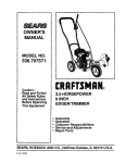
1
!CRRFTSMRWI
Horsepower
9 Inch
EDGER/TRIMMER
MODEL NO.
536.772300
Caution:
Read and follow all Safety
Rules and Operating
Instructions before first use
of this product.
Sears, Roebuck and Co., Hoffman Estates, IL 60179 U.S.A.
711943
05/11/98
Table of Contents
Warranty
Safety Rules
Contents of Shipping Carton
Assembly
Operation
Maintenance
LIMITED
TWO-YEAR
2
2
2-3
4
4-5
5-9
9-10
WARRANTY
Service and Adjustments
Storage
Troubleshooting
Edger/Trimmer Repair Parts
Engine Repair Parts
Spanish (EspaSol)
Parts Ordering/Service
Back
ON CRAFTSMAN
11-12
12-13
13
14-18
19-22
23-36
Cover
EDGER/TRIMMER
For two years from the date of purchase, when this Craftsman Edger/Trimmer is maintained, lubricated, and tuned up according to the operating and maintenance instructions in the owner's manual, Craftsman will repair, free of charge, any defect in material
or workmanship.
If this Craftsman Edger/Trimmer is used for commercial or rental purposes, this warranty applies for only 90 days from the date of purchase.
This warranty does not cover the following:
• Expendable items which become worn during normal use, such as spark plugs, etc.
• Repairs necessary because of operator abuse or negligence, including bent crank
shafts and the failure to maintain the equipment according to the instructions contained in the owner's manual.
WARRANTY SERVICE IS AVAILABLE BY RETURNING THE CRAFTSMAN EDGER/
TRIMMER TO THE NEAREST CRAFTSMAN SERVICE CENTER/DEPARTMENT
IN
THE UNITED STATES. THIS WARRANTY APPLIES ONLY WHILE THIS PRODUCT
IS IN USE IN THE UNITED STATES.
This warranty gives you specific legal rights, and you may also have other rights which
may vary from state to state.
Sears, Roebuck and Co., D817WA,
/_
Hoffman Estates, IL 60179
Look for this symbol to point out Important safety precautions.
ATTENTIONI!!
Become alertll! Your safety is involved.
It means---
A_
CAUTION: Always disconnect spark
plug wire and place wire where it cannot
contact spark plug to prevent accidental
starting when setting-up, transporting,
adjusting or making repairs.
BEFORE USE
• Thoroughly inspect the area where the
Edger/Trimmer
is to be used and remove
all foreign objects.
FUEL SAFETY
• Read the owner's manual carefully. Be
thoroughly familiar with the controls and
the proper use of the Edgar/Trimmer.
Know how to stop the Edger/Trimmer and
disengage the controls quickly.
• Do not operate the Edger/Trimmer
without wearing adequate outer garments. Wear footwear that will improve
footing on slippery surfaces.
• Keep the area of operation clear of all
persons, particularly small children and
pets.
• Use an approved container.
• Check fuel supply before each use,
allowing space for expansion as the heat
of the eng_e and/or sun can cause fuel to
expand.
• Fill fuel tank outdoors with extreme care.
Never fill fuel tank indoors, Replace fuel
tank cap securely and wipe up spilled
fuel.
• Handle fuel with care;it
mable.
• Never
fuel to
• Never
fuel in
2
is highly flam-
remove the fuel tank cap or add
a running or hot engine.
store fuel or Edger/Trimmer with
the tank inside a building where
fumes may reach an open flame.
OPERATING SAFETY
• Never allow children or young teenagers
to operate the Edger/Trimmer.
Keep them
away while it is operating. Never allow
adults to operate the Edger/Trimmer
without proper instruction.
• Do not operate this machine if you are
taking drugs or other medication which
can cause drowsiness or affect your
ability to operate this machine.
• Do not use this machine if you are
mentally or physically unable to operate
this machine safely.
• Always wear safety glasses or eye
shields during operation or while performing an adjustment or repair to protect
your eyes from foreign objects that may
be thrown from the Edger/Trimmer.
• Do not put hands or feet near or under
rotating parts.
• Exercise extreme caution when operating
on or crossing gravel drives, walks, or
roads. Stay alert for hidden hazards or
traffic.
• Exercise caution to avoid slipping or
falling.
• Never operate the Edger/Trimmer without
proper guards, plates, or other safety
protective devices in place.
• Never operate the Edger/Trimmer at high
transport speeds on slippery surfaces.
Look behind and use care when backing.
• Never allow bystanders near the Edged
Trimmer.
• Keep children and pets away while
operating.
• Never operate the Edger/Trimmer without
good visibility or light.
• Do not run the engine indoors. The
exhaust fumes are dangerous, containing
CARBON MONOXIDE, an ODORLESS
and DEADLY GAS.
• Take all possible precautions when
leaving the Edger/Trimmer
unattended.
Stop the engine.
• Do not overload the Edger/Trimmer
capacity by attempting to edge too deep
at too fast a rate.
SAFE STORAGE
• Always refer to the owner's manual
instructions for important details if the
Edger/Trimmer
is to be stored for an
extended period.
• Never store the Edger/Trimmer with fuel
in the fuel tank inside a building where
ignition sources are present such as
water and space heaters, clothes dryers,
and the like. Allow the engine to cool
before storing in any enclosure.
• Keep the Edger/Trimmer in safe working
condition. Check all fasteners at frequent
intervals for proper tightness.
REPAIR/ADJUSTMENTS
SAFETY
• After striking a foreign object, stop the
ertgine (motor). Remove the wire
spark plug, and keep the wire away from
the plug to prevent accidental starting.
Thoroughly inspect the Edger/Trimmer for
any damage, and repair the damage
before restarting and operating it.
• If Edger/Trimmer should start to vibrate
abnormally, stop engine (motor) and
check immediately for the cause.
Vibration is generally a warning of
trouble.
• Stop the blade whenever you leave the
operating position. Also, disconnect the
spark plug wire before unclogging the
blades and when making any repairs,
adjustments, or inspections.
• When cleaning, repairing, or inspecting,
shut off the engine and make certain all
moving parts have stopped.
• Never attempt to make any adjustments
while the engine is running except when
specifically recommended by the manufacturer.
/_
WARNING:
The engine exhaust
from this product contains chemicals known
to the State of California to cause cancer,
birth defects or other reproductive harm.
/_
WARNING:
This unit is equipped
with an internal combustion engine and
should not be used on or near any unimproved forest-covered,
brush-covered or
grass-covered land unless the engine's exhaust system is equipped with a spark arrester meeting applicable local or state laws
(if any). If a spark arrester is used, it should
be maintained in effective working order by
the operator.
In the state of'California the spark arrester
is required by law (Section 4442 of the California Public Resources Code). Other
states may have similar laws. Federal laws
apply on federal lands. A spark arrester/
muffler is available through your nearest
Craftsman Authorized Service Center (See
REPAIR PARTS section in this manual).
Parts
packed
separately
in carton
(not shown
1 - Owner's Manual (not shown)
full size)
1 - Container SAE30 oil
(1) - Hair Pin
,/_
CAUTION:
Always wear safety
glasses or eye shields while assembling
Edger/Trimmer.
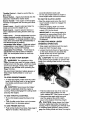
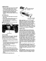
The figure to the right shows the Edger/
Trimmer completely assembled.
References to the right or left hand side
of the Edger/Trimmer are from the viewpoint
of the operator's position behind the unit.
TO REMOVE
EDGER/TRIMMER
FROM CARTON
• Remove the bottle of oil and parts bag
from the carton.
• Cut down all four corners of the carton.
• Remove packing material on Edger/
Trimmer.
• Loosen T-knobs and raise handle to
operator's position allowing control rod to
swing freely.
• Tighten T-knobs. T-knobs should be to
the outside of the handles as shown in
figure below.
• Insert end of control rod left to right
through the hole in the quill support arm.
Attach with hair pin found in parts bag.
See figure below.
•
T-Knob '!_=
'_'"
Hair Pin
Control Rod
Whenthe clutchleveris in NEUTRAL,the quillsupportarm should
becloseto the spacerandscrewbehindit as shownin figurebelow.
,,I CHECKLIST
Before you operate and enjoy your new
Edger/Trimmer,
we wish to assure that you
receive the best performance and satisfaction from this quality product.
PLEASE REVIEW THE FOLLOWING
CH ECKLIST:
Quill
Support
_
,I
All assembly
instructions
have been
completed.
,/
No remaining loose parts in carton.
4"
All fasteners have been tightened.
While learning how to use your
Trimmer, pay extra
important items:
,/',I Engine oil is at proper level.
,I,/" Fuel tank is filled with fresh, clea
I'egular Unleaded gasoline.
,/,/ Become familiar with all controls-their
location and function. Operate
before starting engine.
controls
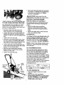
KNOW YOUR EDGER/TRIMMER
READ THIS OWNER'S
MANUAL
AND SAFETY
RULES BEFORE
OPERATING
YOUR
EDGER/TRIMMER.
Compare the illustrations with your EDGER/TRIMMER
to familiarize
yourself with the location of various controls and adjustments. Save this manual for future
reference.
Fast
Slow
Stop
Primer Button
Blade
Guard
Throttle
VIEW OF BLADE AREA
Starter_
Handl_
Wheel
Adjustable
Wheel
5
"_
Throttle Control - Used to control the engine speed.
Primer Button - Injects fuel directly into the
carburetor manifold for faster starts.
seconds between each push.
• Do not use primer button to restart a
warm engine after a short shutdown.
TO USE THE CLUTCH
LEVER
Starter Handle -The engine on this Edger/
Trimmer is equipped with an easy pull recoil
starter.
• Start the engine and move the clutch
lever forward or down to engage the
cutting blade.
Clutch Lever - Used to start and stop the
blade and control the depth of cut.
• Select the edging depth you need.
There are 5 selections up to approximately 2-3/4 inches deep.
Blade Guard - Used to prevent stones or
other material from being thrown at the operator.
Index Lever - Permits adjustment from the
edging (vertical) position to trimming (horizontal) position. To change position, pull the
index lever and rotate the quill assembly to
the desired angle or position.
IMPORTANT:
If very deep edging is
required, we recommend that a shallow cut be made first, then cuts at
greater depths until the desired depth
is obtained.
TO USE THE
INDEX
LEVER
Adjustable Rear Wheel - Right rear wheel
is adjustable to level Edger/Trimmer when
edging along a curb(curb-hopping).
(TRIMMING
Adjustable Front Wheel - Front wheel is
adjustable from side-to-side for balance.
Also, can be adjusted down for curb-hopping.
• Loosen the knob shown in figure below
on the front wheel arm and slide the
wheel all the way to the right side.
HOW TO USE YOUR EDGER
,/_
/_
in the extreme right position to prevent the
blade from striking wheel while in trimming
position.
WARNING:
The operation of this
Edger/Trimmer can result in foreign objects
being thrown into the eyes, which can cause
severe eye damage. Always wear safety
glasses or eye shields while operating the
Edger/Trimmer.
OPERATION)
• Stop engine and disconnect the spark
plug wire from the spark plug.
• Tighten the knob securely.
CAUTION:
The front wheel must be
We recommend standard safety glasses or
Wide Vision Safety Mask for over your
glasses.
TO STOP EDGER/TRIMMER
• To stop the engine, make sure the clutch
lever is all the way back or up and move
the throttle control lever to the STOP
z_osition.
CAUTION:
Knob
Never leave the Edger/
Trimmer unattended while the engine is
running. Always disengage the cutting blade
• Pull the index lever out of its notch as
shown below and position it in the
notch ma_ked 90 °. See figure on page 7.
and stop the engine.
TO USE THROTTLE
CONTROL
• Run at full engine speed during normal
use.
• Push throttle control lever up to increase
speed; down to decrease speed.
TO USE PRIMER
BUTTON
• Push primer button five times. See page 5
figure for location. Wait about two
• Reconnect the spark plug wire and
start the engine. Move the clutch
lever to the desired trimming height.
4=
Z_
CAUTION:
Never leave the Edger/
Trimmer unattended while the engine is
running. Prior to adjusting the wheels and/
or indexing blade position, always disengage the cutting blade and stop the engine.
• Reconnect the spark plug wire and start
the engine. The depth of cut adjustment
is the same as described in Edging
Operation paragraph.
•iK CAUTION:
Keep away from the
rotating blade. The blade can cause injury.
BEFORE
INDEX LEVER IN THE NOTCH MARKED
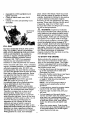
TO USE CURB-HOPPING
"90"
FEATURE
The adjustable front and right rear wheel
feature permit the Edger/Trimmer
to be
used on an uneven surface such as a curb
as shown in figure below.
• Stop the engine and disconnect the
spark plug wire from the spark plug.
• Loosen the knob on the front wheel arm
bracket and slide the wheel to the best
position to clear the curb and balance the
unit.
• Tighten the knob securely.
• Using the curb height adjust lever, lower
the front wheel to a position that places
the Edger/Trimmer
level with the left rear
wheel on the uneven curb surface.
• Loosen tee knob on the inside right rear
of the main frame that secures the wheel
support rod as shown below.
• Slide the rear wheel down until the
Edger/Trimmer
is level when the left
wheel is on the curb.
• Tighten the knob securely.
Blade
Knob
Tee Knob
(Behind _
Wheel)
STARTING
ENGINE
PRE_.USECHECK OF CONTROLS
All controls should be checked for proper
function before servicing or starting the
engine.
• Move the clutch lever into all six
positions in the selector plate. Make
sure the clutch lever snaps into all six
holes.
• Return the clutch lever to the rearmost
hole in the selector plate.
FILIJADD
OIL:
This Edger/Trimmer was shipped with a 20
ounce container of SAE30 motor oil. This
oil must be added to the engine before
operating. Remove the oil fill cap/dipstick
to fill the crankcase. DO NOT OVERFILL.
NOTE:
Engine may already contain some
residual oil. Check frequently
the crankcase.
when filling
OIL RECOMMENDATIONS
Only use high quality detergent oil rated
with API service classification SG. Select
the oil's SAE viscosity grade according to
your expected operating temperature.
A{though mu{ti-viscosity oils (5W30, 10W30,
etc.) improve starting in cold weather, these
multi-viscosity oils will result in increased oil
consumption when used above 32°F.
Check your engine oil level more frequently
to avoid possible engine damage from
running low on oil.
Colder <<
32°F
_
>>Warmer
,"- w3o
" t-- 3o
"{
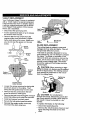
TO ADD ENGINE OIL
Wheel
Rod
Adjust Lever
]
• Place the Edger/Trimmer on a level
surface.
• Remove the oil fill cap/dipstick.
• Fill the engine crankcase, poudng slowly.
DO NOT OVERFILL.
For approximate
capacity see PRODUCT SPECIFICATIONS chart in this manual.
•
Reinstall the oil fill cap/dipstick and
tighten securely.
Check oil before each use. Add if
needed.
Change oil every 25 operating hours
thereafter.
•
•
place; never in the house. Never buy more
than a 30 day supply of gasoline to assure
volatility. Gasoline is intended to be used as
a fuel for internal combustion engines
therefore, do not use gasoline for any other
purpose. Since many children like the smell
of gasoline, keep it out of their reach
because the fumes are dangerous to inhale,
as well as being explosive.
A
Oil Fill Cap/
Dipstick
FILL GAS
NOTICE: ENGINES WHICH ARE CERTIFIED TO COMPLY WITH CALIFORNIA
AND US EPA EMISSION REGULATIONS
FOR ULGE ENGINES: Are certified to
operate on regular unleaded gasoline.
Include the following emission control
system(s): EM, TWC (if so equipped).
Include any user adjustable features therefore no other adjustments are needed.
Fill the fuel tank with clean, fresh, unleaded
regular, unleaded premium, or reformulated
automotive gasoline only. DO NOT use
leaded gasoline. Be sure that the container
you pour the gasoline from is clean and free
from dust or other foreign particles. Never
use gasoline that may be stale from long
periods of storage in the container.
/_
CAUTION"
Never fill the gas tank
wT=iirethe engine is running or hot.
Immediately wipe oft any spilled gasoline
before attempting to start the engine.
4_
an,_ CAUTION:
Gasoline is flammable
caution must be used when handling or
storing it. Do not fill fuel tank while Edger/
Trimmer is running, hot, or when in an
enclosed area. Keep away from open
flame, electrical spark, and do not smoke
while filling the fuel tank. Never fill fuel tank
completely; but fill the tank to within 1/4-1/2
inch from the top to provide space for
expansion of fuel. Always fill fuel tank
outdoors and use a funnel or spout to
prevent spilling. Make sure to wipe up any
spilled fuel before starting the engine. Store
gasoline in a clean, approved container,
and keep the cap in place on the container.
Keep gasoline in a cool, well ventilated
WARNING:
Experience indicates
that alcohol blended fuels called gasohol or
using methanol can attract moisture which
leads to separation and formation of acids
during storage. Acidic gas can damage the
fuel system of an engine while in storage.
To avoid engine problems, the fuel system
should be emptied before storage of 30
days or longer. Drain fuel tank, start engine
and let it run until fuel lines and carburetor
are empty. Use fresh fuel next season. See
Storage Instructions for additional information. Never use engine or carburetor
cleaner products in the fuel tank or permanent damage may occur.
TO START THE ENGINE
Before starting the engine, be sure you
have read and understood all the instructions on the preceding pages. The Edger/
Trimmer is equipped with a recoil starter.
The operation of the engine is controlled by
the throttle control lever.
• Pull the clutch lever all the way back or
up to the rearmost hole to raise and
disengage the blade.
• Move the throttle control lever, see figure
on page 5 to the FAST position.
• Push primer button five times, see figure
on page 5. Wait about two seconds
between each push.
NOTE: Do not use primer button to
restart a warm engine after a short
shutdown.
• To start engine, grasp the engine starter
handle firmly with your right hand.
• Hold the edger handle firmly with your
left hand.
• Pull up sherply on the recoil starter
handle. DO NOT allow the starter rope to
snap back, let it rewind slowly while
holding the starter handle. If engine fails
to start after three pulls, push primer
button two times and pull starter rope
again.
• When the engine starts. Push throttle
control lever up to increase speed; down
to decrease speed. Run at full engine
speed during normal use.
NOTE:The cuttingbladespeedis
controlledby the enginespeed.To
reducethe cuttingbladespeed,push
downon the throttlecontrollever.To
increasethe bladespeed,pushthe
throttlecontrolleverup.
• Tostop the engine, make sure the clutch
lever is all the way back or up and move
the throttle control lever to the STOP
position.
CAUTION:
Never run the engine
indoors or in a poorly ventilated area.
Engine exhaust contains carbon monoxide,
an odorless and deadly gas. Keep hands,
feet, hair and loose clothing away from any
moving parts on the engine or Edger/
Trimmer. Avoid the muffler and surrounding
areas. Temperatures may exceed 150 ° F.
EDGING TIPS
• Edging is best performed when conditions
are dry. If the soil is to wet, dirt becomes
packed in and around the blade causing
premature belt wear and decreased
performance.
plug wire, and remove the packed debris
before continuing to edge.
• If very deep edging is required, we
recommend that a shallow cut be made
first, then cuts at greater depth until the
desired depth is obtained.
• Uniform edging can be performed when
the blade guide rides o_ and against the
surface which you are edging.
• Edging can be customized by varying the
number of passes and by the distance
your blade is from the surface you are
edging.
PRODUCT
SPECIFICATIONS
Horse Power:
4.0
Displacement:
9.52 cu. in. (156 cc)
Gasoline Capacity:
2.0 qt. (unleaded)
Lubrication:
20 oz. SAE-30W
Spark Plug:
Champion C J-8 or
Equivalent
• If dirt does become packed around the
blade, stop the engine, remove the spark
CUSTOMER
RESPONSIBILITIES
SERVICE
RECORDS
SCHEDULE
Fill in dates as
you complete
regular service
After
Before FreEvery Every
First
Each
quently
5
10
2
Use
Hours Hours
Hours
SERVICE
DATES
Every Begin
Before
25
Each
Storage
Hours Season
Lubricate all Pivot Points
LubricateWheel Axles
_'
v"
Check Engine Oil Level
Change Engine Oil
Replace
Air Cleaner
Filter
Check Spark Plug
Check Drive Belt
Tighten All Screws
=I
and Nuts
Check Blade Wear/Damage
Lubricate
quill rod/tube
GENERAL
RECOMMENDATIONS
The warranty on this Edger/Trimmer
does
not cover items that have been subjected to
operator abuse or negligence. To receive
full value from the warranty, the operator
must maintain the Edger/Trimmer
as instructed in this manual. The above chart is
provided to assist the operator in propedy
maintaining the Edger/Trimmer.
LUBRICATION
• After each 25 hours of use of your Edger/
Trimmer, apply light machine oil to all
moving parts, particularly the wheels•
e_
r
j
•
• The oil in the engine crankcase must be
changed after each 25 hours of use
thereafter. See OIL RECOMMENDATIONS in OPERATIONAL
section in this
manual.
TO CHANGE
_
_
,_l_'urn cover to the left
f
(counterclockwise)
_,
to remove
Flange
Retainer
Slot
OIL
Tab
• Disconnect the spark plug wire from the
spark plug.
Turn cover to the right
(cLockwise)to install
• Remove the oil drain plug as shown below and drain the oil into a flat pan.
• After draining all the oil, reinstall the oil
drain plug securely.
Z_ CAUTION:
Never run the engine
without the air cleaner element installed. A
defective air cleaner can result in loss of
engine power and can cause excessive
wear or damage to the engine components
if dirt or dust is permitted to enter the
engine through the carburetor. A damaged
air cleaner, or one that is clogged with dust
or dirt should be replaced immediately.
NOTE: The oil will drain more freely when
the engine is warm.
VIEW FROM REAR
SPARK PLUG
Oil
Clean the spark plug and reset the gap
periodically. Before removing spark plug,
clean the area around its base to prevent
dirt from entering into the engine. Replace
the spark plug if the electrodes are pitted or
burned or if the porcelain is cracked. Clean
the spark plug by carefully scraping the
electrodes with a knife or screwdriver (do
not sand blast or use a wire brush). Be sure
the spark plug is clean and free of foreign
material. Check the electrodes gap with a
wire feeler gauge and reset to .030 inches if
necessary. If a new spark plug is needed,
refer to the PRODUCT SPECIFICATION
on
page 9 for the proper replacement spark
plug.
Plug
AIR CLEANER
Replace the filter once a year; more often
under dusty or dirty conditions. DO NOT
attempt to clean or oil the air filter.
To install a new air filter, do the following:
• Disconnect the spark plug wire from the
spark plug.
• Turn the cover as shown below to the left
counterclockwise
and remove the cover
and the air filter from the flange.
• Discard the air filter.
Before reinstalling the spark plug, coat the
threads lightly with graphite or light oil to
insure easy removal. Tighten the spark plug
firmly into the engine. If a torque wrench is
available, torque the spark plug to 15 footpounds.
• Clean the cover and the flange thoroughly•
• Insert the new air filter into the cover.
• Push the cover firmly against the flange
and turn it to the right clockwise as far as
it will go as shown in figure below. Be
sure the retainers are locked around the
flange.
• Reconnect
CAUTION:
Always stop the engine
and disconnect the spark plug wire before
making any repairs to the Edger/Trimmer.
the spark plug wire.
10
V-BELT REPLACEMENT
Your Craftsman Edger/Trimmer
is equipped
with a V-belt made of a special compound.
If the belt becomes worn or breaks replace
it with an original equipment belt as shown
in the Repair Parts section of this manual.
Never use a substitute.
• Disconnect
Be_uard
Screw
the spark plug wire.
• Put the clutch lever back or up to release
the tension from the belt.
• Remove the two top screws from the
engine pulley cover as shown in figure
below and remove the cover. Make sure
BeltGuard
you do not lose the spacer on the rear
screw.
_
Guard
BLADE REPLACEMENT
The cutting blade is subject to wear and
damage such as nicks and dents. This will
not generally affect its function.
Spacer
This blade is specially designed to not require sharpening. Do not attempt to sharpen
this blade. The blade is reversible. If the
nicks and dents are excessive, remove the
blade, turn it around and reinstall. This will
provide a fresh cutting edge. The blades
should be replaced if both sides are worn
and damaged.
Pulley
Be_t
A_ CAUTION:
ening the blade
shown in figure
must always be
hind the cutting
Control
Lever
Stop
Spacer
Engir
Pu_ey Cover
When removing or tightnut, always use the method
below. The holding wrench
positioned on the nut beblade.
Engine Pulley
Cover Screws
• Loosen the screw securing the belt guide
as shown above to the engine. Then
swing the belt guide away from the belt.
• Remove the two screws from the belt
Blade
guard as shown in next figure.
/K
• Remove the belt from the engine and quill
assembly pulleys and install the new belt.
Do not attempt to
sharpen this blade. Sharpening could damage it and cause it to break, which may further result in injury to yourself or a bystander.
• Install and secure front belt guard.
• Secure the belt guide loosened
CAUTION:
earlier.
• Reinstall the engine pulley cover and
reconnect the spark plug wire.
To replace the blade, do the following:
• Disconnect sparkplug wire.
• Remove the 1/2-20 Iocknut shown in next
figure securing the blade to the drive
shaft.
11
• Remove the blade.
• Install the new blade and reinstall nut.
Tighten the nut securely to 40-45 ft. Ibs.
• Reconnect the spark plug wire.
TO ADJUST
CARBURETOR
The carburetor
shown below has been pre-
set at the factory and readjustment should
not be necessary. However, if the carburetor does need to be adjusted, proceed as
follows:
• Start the engine and let it warm up.
• Set the throttle control to FAST. Adjust
the high speed adjusting screw in until
the engine speed or sound alters. Adjust
the screw out until the engine speed
sound alters. Note the difference between
the two limits and set the screw in the
middle of the range.
• If the engine tends to stall under load or
not accelerate from low speed to high
speed properly, adjust the high speed
screw out in 1/8 turn in_:rements until the
problem is resolved.
• Let the engine run undisturbed for 30
seconds between each setting to allow
the engine to react to the previous
adjustments.
IMPORTANT:
Never tamper the engine
governor, which is factory set for proper
engine speed. Overspeeding the engine
above the factory high speed setting can
be dangerous. If you think the enginegoverned high speed needs adjusting,
contact your nearest Craftsman Service
Center, which has the proper equipment
and experience to make any necessary
L_ Ac jUsting
Screw
lose finger tight
only)
• Close the high speed adjusting screw by
hand.
• Do not over-tighten.
adjustments.
• Then open it 1-1/4 to 1-1/2 turns.
Z_
CAUTION:
Never store your Edged
IMPORTANT:
Trimmer indoors or in an enclosed, poorly
ventilated area. If gasoline remains in the
tank, fumes may reach an open flame,
spark or pilot light from a furnace, water
heater, clothes
dryer, cigarette,
A yearly checkup
or tune-
up by a Craftsman Service Center is a
good way of ensuring that your Edged
Trimmer will provide maximum performance for the next season.
ENGINE
etc.
EDGER/TRIMMER
IMPORTANT:
It is important to prevent
gum deposits from forming in essential fuel
system parts such as the carburetor, fuel
filter, fuel hose, or tank during storage.
Also, experjence indicates that alcoholblended fuels called gasohol or using
ethanol or methanol can attract moisture
which leads to separation and formation of
acids during storage. Acidic gas can
damage the fuel system of an engine while
in storage.
• Clean the Edger/Trimmer
thoroughly;
remove all debris and wipe the unit dry.
• Inspect the Edger/Trimmer
for worn or
damaged parts and tighten all loose
hardware.
• Oil all points described in the Lubrication
paragraph in the Maintenance section of
this manual.
• Store the Edger/Trimmer
in a protected
area and cover for additional protection.
To prevent engine damage (if Edger/
Trimmer is not used for more than 30 days)
follow the steps on next page.
12
oil from the crankcase
• To remove gasoline, run the engine
until the tank is empty and the engine
stops.
cylinder,
could enter the
causing a service problem.
You can keep your engine in good operating
condition during storage by:
• If you do not want to remove gasoline
a fuel stabilizer (such as Craftsman fuel
stabilizer No. 33500) may be added to
any gasoline left in the tank to minimize
gum deposits and acids. If the tank is
almost empty, mix stabilizer with fresh
gasoline in a separate container and add
some to the tank. Always follow instructions on stabilizer container. Then run
engine at least 10 minutes after stabilizer
is added to allow mixture to reach
carburetor. Store Edger/Trimmer
in a
safe place. See CAUTION
under
STORAGE on page 12.
• Changing
oil.
• Lubricating the piston/cylinder area.
This can be done by first removing the
spark plug and squirting clean engine
oil into the spark plug hole. Then cover
the spark plug hole with a rag to absorb
oil spray. Next, rotate the engine by
pulling the starter two or three times.
Finally, reinstall spark plug and attach
spark plug wire.
• Store the Edger/Trimmer
in the wheelsdown, operating position. If the Edger/
Trimmer is stored in any other position,
TROUBLE
Difficult starting
or
Engine runs
erratic
Cutting blade
fails to turn
CAUSE
CORRECTION
Stale fuel
Drain fuel tank. Fill with fresh
fuel
Defective spark plug
Clean and re-gap spark plug
Clogged fuel line
Replace fuel filter
Blocked fuel line or empty fuel tank
Clean fuel line; check gas tank
Carburetor out of adjustment
Have carburetor adjusted
Fouled spark plug
Clean and adjust gap
Clogged air cleaner
Tap clean or replace air cleaner
Jammed due to foreign object
I Clear obstruction
Loose blade
!Tighten
blade retaining nut
Defective belt
Replace V-belt
Defective quill bearings
Replace the quill assembly
Blade fails to cut
properly
Damaged or worn blade
Reverse blade or replace blade
Excessive
vibration
Loose parts
Stop engine immediately; tighten
air bolts. If vibration continues,
take the unit into the nearest
Craftsman Service Center
13
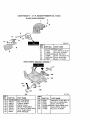
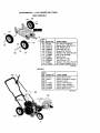
CRAFTSMAN
9" -4 H.P. EDGER/TRIMMER
536.772300
ENGINE ASSEMBLY
Note: Always use original equipment
pads. Use of service/replacement
partsother than original parts may void
your warranty.
REF.
NO. PART NO.
10
ENGINE
12
20
22
24
47792
314781
181608
120638
26
29
30
32
45602
32668
313011
51600
All unnumbered
interchangeable
side
REF.
NO. PART NO.
PART NAME
40
41
42
4 HP 143.984001
(See Engine pages)
Screw, 3/8-16 x 1.00TAP
Pulley, Half V3L
Screw, 5/16-24x 1.00 HHC
Washer, SPTLK
.328x.60x.09
Washer, Flat .333x.87x.11 c.
Belt, V 4L 32.60LG
Screw and Washer Assy
Guide, Belt
331281-848
181624
315095
43 173030
44 308237
45 315095
8O
81
323534-848
308154-848
711943
items are
with opposite
PART NAME
Cover, Engine Pulley
Screw, 5/16-24x3.00 HHC
Spacer, Sleeve
.335x.431 x2.50
Screw, 5/16-24x3.75
Spacer, .3221D .562 OD
Spacer, Sleeve
.335x.431x2.50
Frame, Assy Edger
Strap
Owner's Manual ENG/SP
323095E
14
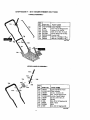
CRAFTSMAN
9" -4 H.P. EDGER/TRIMMER
536.772300
BLADE GUARD ASSEMBLY
1
/.
2
¸¸¸
4
332247E
REF.
NO. PART NO.
PART NAME
1
2
4
5
6
8
9
Blade Guard
Carr. Bolt 5/16-18x.63
Nut, 5/16-18 Wdfllk
Guide, Belt Front
Screw, 1/4-20x.50 Tap
Cover, Quill Pulley
Screw, 10-16x.50
331O76-848
57072
710205
326748-848
710264
53405-848
710271
FRONT WHEEL BRACKET ASSEMBLY
156
331765E
159
REF.
NO.
150
151
152
153
154
155
156
157
PART NO.
PART NAME
339299-84_ Arm, Front Wheel
740132
Rod, Front Mount
338614
Pushnut, Washer
325892
Washer, Plastic
331421
Spacer, Height Adjust
332002
Pin, Spring .187Diax1.50L_
331419
Lever, Height Adjust
20252
Knob, Rectangle
REF.I
NO. PART NO.
158
159
160
161
163
164
22265
45905
51333
331394-848
339388
710205
PART NAME
Flatwasher .515xl .38x.119
Nut, 3/8-16 Hwdfllk Mack
Screw, 5/16-18x.63
Plate, Height Adjust Quad
Knob, W/5/16-18 Stud
Nut, 5/16-18 Wdfllk
CRAFTSMAN9" - 4H.P.
EDGER/TRIMMER
CURB HOPPER ASSEMBLY
184
536.772300
183
172,
323179D
REF.
NO.
PARTNO.
170 i6842
171
180077
172
1498
180
126380
1181
8082
182
45222
183
120393
184
13627
185
120376
186
310896
PART NAME
Bracket, Curb Hop Mnt
Screw, 5/16-18x,75
Nut, 5/16-18 Reghexctrlk
Carr. Bolt, 5/16-18x2.00
Clevis
Spacer, Slev .356x.63x1,01
Flatwasher .344x.69x.065
Knob, T
Nut, 5/16-18 Reghex
Rod, Wheel Support
BLADE ASSEMBLY
323321
325
311
310
305
REF.
NO.
PART
300
301
302
305
310
311
320
120396
338656-848
308254
780072
308243
710271
51603
NO.
PART NAME
Flatwasher, .531x1.06x.095
Quill Suppt. Assy.
Shoulder Bolt 3/8-16
Nut, 3/8-16 Reghexctdk
Deflector, Rubber
Screw, 10-16x.50 Tap
Compression Spring
323129C
REF.
NO.
PART NO.
321
322
323
325
329
330
331
338070
308466
308155
1498
22265
308344-853
46023
PART NAME
Quill Assembly, Lrg Suppt.
Index Lever
Torsion Spring
iNut, 5/16-18 Reghexctrlk
Flatwasher, .515xl .38x.119
Blade Edger
Nut, 1/-20 Wdfl
CRAFTSMAN
9" - 4H.P. EDGER/TRIMMER
536.772300
HANDLE ASSEMBLY
REF.
NO. PART NO.
720
721
722
424
425
750
751
754
750
74012%853
1498
51333
315288
671294
580292-853
36368
36368
PART NAME
Lower Handle
Nut, 5/16-18 Reghexctdk
Screw, 5/16-18x.63
Bolt, 5/16-18xl .75 CUH
Knob, Wing 5/16-18 Nut
Control Rod
Hair Pin .072Diax1.13Lg
Hair Pin .072Diax1.13Lg
343718A
721
UPPER HANDLE ASSEMBLY
743
725
731
I
!
739
738
REF
NO.
PART NO.
725 740147
731 310052-853
732 180024
735 782585 °
737 310050-853
738 180081
739 25644
740 I 1498
741 56924
743 310053
745 1499
PART NAME
Upper Handle & Foam
Plate Selector
Screw, 1/4-20xl .25
Nut, 1/4-20 Reghexctrlk
Handle, Depth Adjust
Screw, 5/16-18xl .25
Spring
Nut, 5/16-18 Reghexctdk
Gdp, Hand
Stud
Nut, 3/8-16 Reghexctrlk
323136F
17
CRAFTSMAN
9" - 4 H.P. EDGER 536.772300
TIRES ASSEMBLY
105
lO8
!
116
117
REF.
11 NO. PART NO.
103
105
106
108
109
110
111
113
114
116
117
118
11o
114
41529
310715
310716
336545
180113
120393
710205
51887
336546
336545
2968
121222
PART NAME
Nut, 3/8-16 Hxctrlkjam
Spacer, Slev .390x.70x.70
Bolt, HHSH 3/8-16
Tire & Rim 8xl.75
Screw 5/16-18x3.00
Washer, Flat .344x.69x.065
Nut, 5/16-18 Wdfllk
Spacer, Slev
Tire & Rim 7xl .50
Tire & Rim 8xl .75
Washer, Flat .504x.75x.059
Pin, Cotter .090Diax.75Lg
343720A
DECALS
REF.
NO. PART NO.
820
821
822"
823
824
825
826
712114
69711
711737
402881
312548
333874
PART NAME
Decal, Recoil Cover
Decal, Information Danger
Reference Only
Decal, 4.0HP Engine
Decal, Angle Indicator
Decal, Quadrant Selector
Decal, Blade Cover
343717A
826
I
18
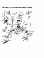
CRAFTSMAN
4-CYCLE
ENGINE MODEL NUMBER:
143.984001
Carburetor No.640049
17
I
I
30
31
_-REF, PART
NO. NO.
0
640049
1
2
4
5
6
7
16
17
18
20
20A
25
27
28
29
30
31
35
36
37
40
44
47
48
631615
631767
631184
631183
631036
650506
632164
650417
630766
640018
640053
1631867
631024
632019
631028
631021
631022
36045A
632745
632547
640050
27110
630748
631027
PART NAME
Carburetor
I (Incl. 164 of Engine Parts List)
Throttle Shaft & Lever Ass'y.
Throttle Return Spring
Dust Seal Washer
Dust Seal (Throttle)
Throtter Shutter
Shutter Screw
Fuel Fitting
Throttle Crack Screw/Idle Speed Screw
Tension Spring
Idle Restdctor Screw
Idle Restr_ctorScrew Cap
Float Bowl
Float Shaft
Float
Folat Bowl "O" Ring
Inlet Needle, Seat, Clip (inc131)
Spring Clip
Primer Bulb/Retainer Ring
Main Nozzle Tube
"O" Ring, Main Nozzle Tube
High Speed Bowl Nut
Bowl Nut Washer
Welch Plug, idler Mixture Well
Welch Plug Atmospheric Vent
,_:37
25
4O
37
CRAFTSMAN
4-CYCLE
ENGINE MODEL NUMBER:
143.984001
4262
370C
"-,.
238
_241
285
"-,,
._'_'_n
/
370K
• CRAFTSMAN
4-CYCLE
ENGINE MODEL NUMBER:
143.984001
i REF.
REF,
NO.
PART NO.
1
2
14
15
16
17
18
19
20
25
36560
26727
28277
31334
31336
31335
651018
34593
32600
36552
25A
26
26A
30
40
40
35883
650802
650926
35902
40020
40021
41
40018
41
40019
42
42
43
45
40022
40023
20381
30963B
46
48
49
5O
60
65
69*
7O
32610A
27241
28594
32197A
29745
650128
27677A
34863A
72
75
80
81
82
27642
26208
30574A
30590A
30591
83
86
89
90
92
93
100
102
30588A
$50488
610961
611195
B50815
650816
34443A
651024
103
551007
110
119 *
120
125
35182
36437
36438
36471
125
36472
126
126
29314B
29315C
130
130A
132
135
650694A
6021A
650708
33636
PART NAME
Cylinder (Incl. 2,20,72 &125
Dowel Pin
Washer
Governo Rod
Governor Lever
Governor Lever Clamp
Screw, 8-32 x 19/64"
Extension Spring
Oil Seal
Blower Housing Baffle
(Incl. 262)
Baffle Extension
Screw, 1/4-20 x 5/18"
Screw, 8-32 x 21/64"
Crankshaft
Piston,Pin&Ring Set(std)
Piston,Pin & Ring Set
(0.010 OS)
Piston & Ring Assy
(Std) (Inc143)
Piston & Pin Assy
(.010" OS) Inc143
Ring Set (Std)
Ring Set (,010" OS)
Piston Pin Retain Ring
Connecting Rod Assy
(Inc146 & 49)
Connecting Rod Bolt
Valve Lifter
Oil Dipper
Camshaft (MCR)
Blower Housing Ext.
Screw, 10-24 x 1/2"
Cylinder Cover Gasket
Cylinder Cover
(Incl 75 thru 83, 311)
Oil Drain Plug
Oil Seal
Governor Shaft
Washer
Governor Gear Assy
(Incl 81 )
Governor Spool
Screw 1/4-20 x 1-1/4"
Flywheel Key
Flywheel
Belleville Washer
Flywheel Nut
Solid State Ignition
Solid State
Mounting Stud
Screw, Torx T-15,
10-24 x 15/16"
Ground Wire
Cylinder Head Gasket
Cylinder Head (Inc. 130)
Exhaust Valve (Std)
(Inc1.151)
Exhaust Valve (1/32" OS)
(Inc1151)
Intake Valve (Std) (Ine1151 )
Intake Valve (1/32" OS)
(Inc1151)
Screw 5/16-18 x 2"
Screw, 5/16-18 x 1-1/2"
Washer
Resistor Spark Plug
NO.
PART NO
150
151
169"
170
171
172 '
173
173A
174
178
179
182
184 *
31672
31673
27234A
27666
31410
34146
32447
32446
650783
29752
30593
6201
26756
185
36703
186
200
31341
36677
203
204
31342
651029
206
209
209A
215
223
224"
238
239*
241
245
250
260
262
275
277
.285
_287
290
292
298
300
301
305
307
308
310
313
339
340
342
345
370A
370B
370C
370K
380
390 0
40O
610973
650139
30322
32410
650451
26754A
650932
34338
35797
35066
35065
35585
650737
40000
650988
36467A
650926
29774
26460
650665
35591
36246
35554
35499
35539
35582
34080
28212
35926
650751
32664
3626_
35703
36861
36695
640049
590732
36439
416
35085
417
650760
0This engine
590738starter.
21
PART NAME
(RJ17LM)
Valve Spring
Valve Spring Cap
Valve Cover Gasket
Breather Body
Breather Element
Valve Cover
Breather Tube
Breather Tube Gommet
Screw 10-24 x 3/4"
Nut & Lock Washer 1/4-28
Retainer Clip
Screw 1/4-28 x 7/8"
Carburetor to intake
Pipe Gasket
Intake Pipe
(Inc. 182, 184,224)
Governor Link
Control Bracket (Incl.
203 thru 209A)
Compression Spdng
Screw, Torx T-10,
5-40 x 7/1"6"
Terminal
Screw 8-32 x 1/2"
Lock Nut 8-32
Control Knob
Screw 1/4-20 x 1"
Intake Pipe Gasket
Screw 10-32 x 49/64"
Air Cleaner Gasket
Air Cleaner Collar
Air Cleaner Filter
Air Cleaner Cover
Blower Housing
Screw 1/4-20 x 1/2"
Muffler
Screw 1/4-20 x 2-5/16"
Starter Cup
Screw 8-32 x 21/64"
Fuel Line
Fuel Line Clamp
Screw, t/4-15 x 7/8"
Fuel Tank(In 292&301)
Fuel Cap
Oil Fill Tube
"O" Ring
Fill Tube Clip
Dipstick
Spacer
Spacer
Fuel Tank Bracket
Screw, 1/4-20 x 7/16"
Baffle Heat
Lubrication Decal
Control Decal
Primer Decal
Starter Decal
Carburetor (Inc1184)
Rewind Starter
Gasket Set
Includes items marked*
Spark Arrestor Kit
Incl 417 (Opt)
Screw. 8-32x3/8" <Oot_
could have been built with
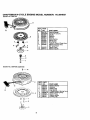
CRAFTSMAN
4-CYCLE
ENGINE MODEL NUMBER:
143.984001
Starter No. 590732
mll
REF
NO.
13
1
2
3
4
5
6
7
8
11
PART
NO.
590732
590599A
590600
590696
590601
590697
590698
590699
590700
590695
12
13
590535
590701
PART NAME
Rewind Starter
Spring Pin (Incl.4)
Washer
Retainer
Washer
Brake Spring
Starter Dog
Dog Spring
Pulley & Rewind Sprg Assy
Starter Housing Assy
(40 ° grommet)
Starter Rope
Starter Handle
Starter No. 590738 (optional)
_
14
REF, PART
NO, NO.
590738
3
590740
590616
7
590617
590618A
11 590687A
590535,
13 590701
590741
12
13
(
_
:
II
111--7
C__
_ ' n_
22
PART NAME
Rewind Starter
Retainer
Starter Dog
Dog Spring
Pulley&Rewind Spring Ass_
Starter Housing Assy
Starter Rope
Starter Handle
LockingTab
37
38
39
For the repair or replacement parts you
need delivered directly to your home
Call 7 am-7 pm, 7 days a week
1-800-366-PART
(1-800-366-7278)
Para ordenar piezas con entrega
a domicilio -1-800-659-7084
For in-house major brand repair service
Call 24 hours a day, 7 days a week
1-800-4-REPAIR
(1-800-473-7247)
Para pedir servicio de reparaci6n
domicilio - 1-800-676-5811
a
For the location of a Sears Parts and
Repair Center in your area
Call 24 hours a day, 7 days a week
1-800-488-1222
For information on purchasing a Sears
Maintenance Agreement or to inquire
about an existing Agreement
Call 9 am-5 pm, Monday-Saturday
1-800-827-6655
When requesting service or ordering
parts, always provide the following
information:
• Product Type
• Part Number
• Model Number
• Part Description
America's
Repair
Specialists
Printed in U.S.A,